JP6431402B2 - Cutting tool fixing structure - Google Patents
Cutting tool fixing structure Download PDFInfo
- Publication number
- JP6431402B2 JP6431402B2 JP2015031607A JP2015031607A JP6431402B2 JP 6431402 B2 JP6431402 B2 JP 6431402B2 JP 2015031607 A JP2015031607 A JP 2015031607A JP 2015031607 A JP2015031607 A JP 2015031607A JP 6431402 B2 JP6431402 B2 JP 6431402B2
- Authority
- JP
- Japan
- Prior art keywords
- sleeve
- cutting tool
- adjustment
- center
- tool
- Prior art date
- Legal status (The legal status is an assumption and is not a legal conclusion. Google has not performed a legal analysis and makes no representation as to the accuracy of the status listed.)
- Active
Links
Images

Landscapes
- Cutting Tools, Boring Holders, And Turrets (AREA)
Description
本発明は、刃物台に対してドリル等の切削工具をスリーブを介して固定する切削工具の固定構造に関する。 The present invention relates to a cutting tool fixing structure for fixing a cutting tool such as a drill to a tool post via a sleeve.
例えばタレット旋盤は、刃物台であるタレットに複数の切削工具が取り付けられ、使用する切削工具が旋回割出しにより選択され、その切削工具により主軸に回転保持されたワークに対する加工が実行される。複数ある切削工具のうちドリルなどの切削工具は、工具ホルダに対してスリーブなどを介して固定される。そうした切削工具でワークを加工する場合、正確な寸法で加工するため工具の正確な位置決めが必要になる。例えば、ドリルによってワークに穴あけ加工を行う場合は、ドリルの軸心と主軸の軸中心とのズレ量、つまり芯高を±0.05mm程度にまで収めることが求められる。 For example, in a turret lathe, a plurality of cutting tools are attached to a turret which is a tool post, a cutting tool to be used is selected by turning indexing, and machining is performed on a workpiece which is rotated and held on a main shaft by the cutting tool. Among a plurality of cutting tools, a cutting tool such as a drill is fixed to a tool holder via a sleeve or the like. When machining a workpiece with such a cutting tool, it is necessary to accurately position the tool in order to machine with a precise dimension. For example, when drilling a workpiece with a drill, it is required that the amount of misalignment between the axis of the drill and the axis center of the spindle, that is, the center height be kept within about ± 0.05 mm.
この点、下記特許文献1では偏芯スリーブを使用した切削工具の固定構造が開示されている。すなわち、偏芯スリーブに軸心を有するドリル等が挿入され、偏芯スリーブの回転により芯高調整を行うものである。より具体的には、工具ホルダに円筒形状をした偏芯スリーブを挿入する円形の取り付け孔が形成され、偏芯スリーブは、外径円の中心と内径円の中心とがずれた偏心形状で形成されている。そして、偏芯スリーブを工具ホルダ内で回転させることにより、切削工具の軸心と重なる偏芯スリーブの内径円の中心が芯高方向に移動することにより芯高調整が行われる。
In this regard,
しかし、前述したようにズレ量の許容範囲はミクロン単位であり、芯高調整は極めて微小な寸法の範囲内で行うものである。そのため、前記従来例の固定構造によれば、調整作業に伴うスリーブの取り扱いが容易になるとはいえ、調整自体は微細な作業である。従って、段取り替えなど、タレットに対して切削工具の着脱が行われる度に微細な調整作業が必要となり、その芯高調整に長い作業時間を要してしまっていた。また、前記従来例の固定構造に限らずこれまでの芯高調整には再現性がなかったため、切削工具を着脱させる度に同じ調整作業を繰り返し行わなければならなかった。 However, as described above, the allowable range of deviation is in units of microns, and the center height adjustment is performed within a very small size range. Therefore, according to the fixing structure of the conventional example, although the handling of the sleeve accompanying the adjustment work becomes easy, the adjustment itself is a fine work. Therefore, every time the cutting tool is attached to or detached from the turret, such as setup change, fine adjustment work is required, and adjustment of the center height requires a long work time. Moreover, since the center height adjustment so far was not reproducible, not limited to the conventional fixing structure, the same adjustment work had to be repeated each time the cutting tool was attached / detached.
そこで、本発明は、かかる課題を解決すべく、再現性を有する切削工具の固定構造を提供することを目的とする。 Accordingly, an object of the present invention is to provide a cutting tool fixing structure having reproducibility in order to solve such a problem.
本発明に係る切削工具の固定構造は、刃物台の工具ホルダに形成された装着部に筒形状のスリーブが装着され、軸心を有する切削工具が、前記スリーブに挿入された状態で前記刃物台に固定されるようにしたものであって、前記スリーブは、円形断面からなる内側面と偶数の多角形断面からなる外側面とを有し、前記内側面を構成する円の中心から径方向に見て直行する前記外側面の複数の平面までの各々の距離が異なる調整距離として設定され、前記工具ホルダは、前記スリーブの外側面のうち特定の平面が位置決め方向に当てられる基準面が前記装着部に設けられ、前記切削工具が、前記特定の平面を前記工具ホルダの基準面に当てて位置決めされた状態の前記スリーブを介して前記刃物台に固定されるものである。 In the cutting tool fixing structure according to the present invention, a cylindrical sleeve is mounted on a mounting portion formed in a tool holder of a tool post, and the tool post in a state where a cutting tool having an axial center is inserted into the sleeve. The sleeve has an inner surface having a circular cross-section and an outer surface having an even-numbered polygonal cross section, and is arranged in a radial direction from the center of a circle constituting the inner surface. Each distance to the plurality of planes of the outer surface that is perpendicular to the set is set as a different adjustment distance, and the tool holder has a reference surface on which a specific plane of the outer surface of the sleeve is applied in the positioning direction is mounted. The cutting tool is fixed to the tool post via the sleeve in a state of being positioned with the specific plane applied to a reference surface of the tool holder.
本発明によれば、複数ある外側面の平面のうち特定の平面を工具ホルダの装着部に形成された基準面に当ててスリーブが取り付けられ、そうして位置決めされたスリーブに切削工具が挿入され、刃物台に固定される。その際、スリーブの内側面を構成する円の中心から外側面の特定の平面までの調整距離によって、切削工具の軸心位置が調整されることになる。そのため、切削工具を固定する場合には、特定の平面を基準面に当てて取り付けることにより、切削工具の軸心位置を調整した一定の固定状態が再現できる。 According to the present invention, the sleeve is attached by placing a specific plane out of the plurality of planes on the outer surface against the reference surface formed on the mounting portion of the tool holder, and the cutting tool is inserted into the sleeve thus positioned. Fixed to the tool post. At that time, the axial center position of the cutting tool is adjusted by the adjustment distance from the center of the circle constituting the inner surface of the sleeve to the specific plane of the outer surface. Therefore, when the cutting tool is fixed, a fixed state in which the axial center position of the cutting tool is adjusted can be reproduced by attaching a specific plane to the reference plane.
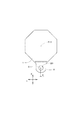
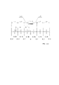
次に、本発明に係る切削工具の固定構造について、その一実施形態を以下に図面を参照しながら説明する。例えばNC旋盤では、主軸チャックに工作物(ワーク)が保持され、主軸の回転によってワークが回転し、そのワークに切削工具が当てられて所定の加工が行われる。そうしたNC旋盤では、刃物台であるタレットに複数の各種切削工具が取り付けられ、タレットの旋回割出しによって加工に応じた切削工具が選択される。図1は、8角形のタレットに対して一の切削工具を取り付けた平面図であり、特に切削工具として軸心を有するドリルに関するものが示されている。 Next, an embodiment of a cutting tool fixing structure according to the present invention will be described below with reference to the drawings. For example, in an NC lathe, a workpiece (workpiece) is held by a spindle chuck, the workpiece is rotated by the rotation of the spindle, and a cutting tool is applied to the workpiece to perform predetermined processing. In such an NC lathe, a plurality of various cutting tools are attached to a turret which is a tool post, and a cutting tool corresponding to processing is selected by turning indexing the turret. FIG. 1 is a plan view in which one cutting tool is attached to an octagonal turret, and particularly relates to a drill having an axis as a cutting tool.
タレット1にはドリル用の工具ホルダ2が装着され、その工具ホルダ2を介して切削工具が固定される。工具ホルダ2は、前記従来例のものと同様に、ドリルの取り付け方向に貫通した取付孔201が形成され、図は省略するが、そこにスリーブを介してドリルが装着される。例えば、円形の取付孔201の中心O1にドリルの軸心が重なるスリーブ(前記従来例のような偏芯スリーブでないもの)であれば、この中心O1を基準にドリルによる加工のための位置制御が行われる。従って、タレット1に取り付けた工具ホルダ2の位置、つまり取付孔201の中心O1を基準位置(主軸の軸中心)に一致させる必要がある。特に、NC旋盤がZ軸方向及びX軸方向の駆動制御を行う2軸旋盤であれば、駆動制御による加工調整ができないY軸方向は、取付段階で同方向の芯高調整が必要になる。
A
図1の場合、タレット1の取付辺に沿った方向がY軸方向である。そこで、中心O1が図示する寸法AだけY軸方向にずれていた場合には、そのズレを解消するための芯高調整が必要になる。従来では、工具ホルダ2をタレット1に対して取り付ける際、偏芯ピンを使用して芯高調整が行われたり、前記従来例のような偏芯スリーブを使用した芯高調整が行われていた。しかし、いずれの調整方法も再現性が無く、切削工具を取り付ける度に同じ調整作業を繰り返す必要があった。また、芯高調整はミクロン単位の調整が必要な微細な作業であるため、加工を実施するまでの調整作業に時間がかかってしまうほか、個人差が生じやすいものでもあった。
In the case of FIG. 1, the direction along the attachment side of the
ところで、NC旋盤では、ワークの加工内容によって使用する切削工具などが異なるため、加工内容の切り替え時には切削工具の段取り替えが行われる。芯高調整は、そうした段取り替えの際に行われるが、その段取り替えでは、同じ工具ホルダやスリーブが繰り返し使用される。従って、寸法公差などによって生じる組み付け時のズレ量Aはほぼ一定である。それにも拘わらず同じ作業が繰り返えし行われ、特に偏芯ピンや偏芯スリーブを使用する従来の固定構造では、芯高調整に時間がかかっていたため加工効率を低下させる原因ともなっていた。そこで、本実施形態では、こうした微細な調整作業を繰り返し行う必要がない切削工具の固定構造を提案する。 By the way, in the NC lathe, the cutting tool to be used differs depending on the machining content of the workpiece. Therefore, the cutting tool is replaced when the machining content is switched. The center height adjustment is performed at the time of such a setup change, and the same tool holder and sleeve are repeatedly used in the setup change. Therefore, the amount of deviation A during assembly caused by dimensional tolerances is substantially constant. Nevertheless, the same operation is repeated, and particularly in the conventional fixing structure using the eccentric pin or the eccentric sleeve, it takes time to adjust the center height, which causes a reduction in processing efficiency. Therefore, in the present embodiment, a cutting tool fixing structure that does not require repeated fine adjustment operations is proposed.
具体的な構成を説明する前に、先ず切削工具の取り付けでは、ズレ量Aに対して許容値が設定されている。一方で、ずれ量Aを生じさせる工具ホルダ2など、固定構造に使用する部品の寸法公差は、加工精度の向上により一定範囲に抑えられるようになってきている。例えば、本実施形態の対象工具であるドリルの場合、ドリルの軸心に関するズレ量Aの許容値が±0.05mmであるのに対し、寸法公差などによる取り付け時の実際の最大取付誤差(最大ズレ量A)は±0.3mm程度にまで抑えられている。本実施形態では、こうした事実を踏まえて構成された切削工具の固定構造である。
Before describing the specific configuration, first, an allowable value is set for the deviation amount A in the attachment of the cutting tool. On the other hand, the dimensional tolerance of parts used for the fixed structure such as the
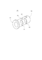
図2は、本実施形態の固定構造に用いられるスリーブを示した斜視図である。このスリーブ10は、フランジ部11と筒形状部12とから構成されたものであり、内側には軸方向に貫かれた円柱状の取付孔13が形成されている。そして、特にスリーブ10の筒形状部12は、取付孔13を構成する内側面15が円形断面である一方、外側面16は8角形の断面によって形成されている。すなわちスリーブ10の外側面16には、円周方向に8つの平面が形成されている。
FIG. 2 is a perspective view showing a sleeve used in the fixing structure of the present embodiment. The
ドリルなどの軸心を有する切削工具は、その固定部分が取付孔13内に挿入され、スリーブ10を介して工具ホルダに対して固定される。そのため、スリーブ10のフランジ部11には、径方向に貫通した工具固定用のネジ孔21が形成され、筒形状部12には、工具ホルダに固定するためのボルトが通る貫通孔22が形成されている。貫通孔22は、筒形状部12の8面各々に2か所ずつ形成されている。ただし、隣り合う平面の貫通孔22同士が近いと、その間の肉が薄くなってスリーブ10の剛性を低下させてしまうため、隣り合う平面の貫通孔22は軸方向に位置がずれている。
A cutting tool having a shaft center such as a drill is fixed to the tool holder via the
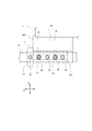
次に、図3及び図4は、本実施形態の切削工具の固定構造を示した図であり、図3は平面図で、図4は図3の図面右側(Y軸方向)から見た側面図である。工具ホルダ30は、図1に示す工具ホルダ2と同様に、8角形のタレット1の一辺に固定されるものであり、その固定側とは反対の側面301側に切削工具6を取り付けるための装着部31が形成されている。装着部31は、Z軸方向(図面を貫く方向)に平行な壁面を有する溝形状の凹部である。なお、本実施形態では、タレット1の回転軸方向が主軸に平行なZ軸方向であり、タレット1の中心O3から見て旋回割出しされた切削工具6の方向がX軸方向であり、そうしたZ軸及びX軸に直交する方向がY軸方向である。
Next, FIG. 3 and FIG. 4 are diagrams showing the fixing structure of the cutting tool of the present embodiment, FIG. 3 is a plan view, and FIG. 4 is a side view seen from the right side (Y-axis direction) of FIG. FIG. The
よって、切削工具6が旋回割出しされた図3の状態で見た場合、溝形状の装着部31は、Y軸方向に直交する2つの側面33,35と、その間に位置してY軸方向と平行になる1つの底面34とを有している。スリーブ10は、装着部31の中に筒形状部12が入れられ、フランジ部11が工具ホルダ30の側面302に当てられて取り付けられる。その際、装着部31内の筒形状部12は、外側面16の2つの平面が側面33と底面34に当てられるようにして位置決めされる。そして、側面35側からY軸方向に形成されたネジ孔24にボルト25がねじ込まれ、切削工具6及びスリーブ10が、そのボルト25によって工具ホルダ30に対しY軸方向に抑え付けられる。
Therefore, when viewed in the state of FIG. 3 in which the
工具ホルダ30には、Z軸方向に4つのネジ孔24が形成されているが、これはスリーブ10に形成された貫通孔22に対応させるためである。すなわち、スリーブ10の筒形状部12には隣り合う平面で貫通孔22の位置が異なり、軸方向に見て4箇所に貫通孔22が位置するためである。そして、このように4つのねじ孔24が存在するのは、8面ある外側面16の平面のうち一の平面だけを工具ホルダ30の側面33に当ててスリーブ10を固定するわけではないからである。
The
つまり、本実施形態では、スリーブ10の外側面16に形成された8つの平面のうち、選択された特定の平面160が装着部31の側面33に当てられることによって芯高調整が実行される。そのため、以下の説明では、スリーブ10の特定の平面160がY軸方向に当てられることになる装着部31の「側面33」を「基準面33」と記載することとする。また、特定の平面160は、スリーブ10に形成された8つの平面のうち、芯高調整により特定されたいずれか一つの面を示すものである。
That is, in the present embodiment, the center height adjustment is executed by applying a selected
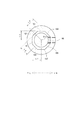
ここで、図5は、スリーブ10による芯高調整のための構成を示した図である。スリーブ10は、8つの平面161〜168が円周方向に形成された外側面16と、円柱形状の部品挿入空間を構成する断面円形の内側面15とを有している。そして、このスリーブ10は、内側面15の円の中心O2から外側面16の各平面161〜168に直交する径方向に見た、中心O2から各平面161〜168までの距離が各々異なるように設計されている。先ず、中心O2から平面161までの距離L1は、工具ホルダ30の基準面33に平面161を当接させた場合に、切削工具6の軸心(中心O2に一致するものとする)と主軸の軸中心とのY軸方向のズレ量A(図1参照、以下同じ)がゼロになるように設定された調整距離である。ゆえに平面161はズレ量ゼロの調整面である。
Here, FIG. 5 is a view showing a configuration for adjusting the core height by the
次に、中心O2から平面162までの距離L2は、工具ホルダ30の基準面33に平面162を当接させた場合に、切削工具6の軸心と主軸の軸中心とのY軸方向のズレ量Aが0.05mmになるように設定された調整距離である。従って、平面162はズレ量Aが0.05mmの調整面である。同じように、中心O2から平面163までの距離L3は、ズレ量Aが0.15mmになるように設定された調整距離であり、中心O2から平面164までの距離L4は、Y軸方向のズレ量Aが0.25mmになるように設定された調整距離である。従って、平面163,164は、それぞれズレ量Aが0.15mm、0.25mmの調整面である。
Next, the distance L2 from the center O2 to the
なお、本実施形態では、基準面33から中心O2が遠ざかるYR方向のズレ量を正とし、反対に中心O2が基準面33に近づくYL方向のズレ量を負としている。そこで、中心O2から平面165までの距離L5は、平面161の反対に位置するズレ量がゼロになるように設定された調整距離であり、中心O2から各平面166,167,168までの距離L6,L7,L8は、それぞれズレ量Aが−0.05mm、−0.15mm、−0.25mmになるように設定された調整距離である。従って、平面165,166,167,168は、それぞれズレ量Aがゼロ、−0.05mm、−0.15mm、−0.25mmの調整面である。
In the present embodiment, the amount of deviation in the YR direction in which the center O2 moves away from the
このように、スリーブ10の各平面161〜168は、芯高調整のための調整面になっている。そこで、以下の説明では「平面」161〜168を「調整面」161〜168と記載することとする。また、調整面161〜168のうちいずれか一つの面を芯高調整によって特定した場合は、「調整面160」として説明する。
Thus, each plane 161-168 of the
次に、図6は、スリーブ10を使用した芯高調整を概念的に示した図である。横軸中央にズレ量ゼロ(Y0)が位置し、左右両方向に離れるに従ってズレ量が大きくなるように示したものである。そして、横軸の下方にはズレ量に対する値が示され、横軸の上方には、ズレ量に対応する前述した調整面161〜168の各適応範囲が示されて。こうして範囲分わけされた各調整面161〜168における調整距離L1〜L8は、切削工具6のズレ量の許容値±0.05mmを基準に設定されている。具体的には、ズレ量がゼロの他、許容値である0.05mm、−0.05mm、そして許容値に対して許容値の倍数を更に整数倍(1倍,2倍,−1倍,−2倍)して加算した0.15mm、0.25mm、−0.15mm、−0.25mmである。
Next, FIG. 6 is a diagram conceptually showing the center height adjustment using the
このように調整距離の設定に当たり許容値を整数倍しているが、本実施形態では2倍(−2倍)の0.25mm(−0.25mm)までである。これは前述したように、寸法公差などによる取り付け時の最大取付誤差が±0.3mm程度にまで抑えられているからである。従って、切削工具の組み付け想定誤差を±0.3mmとして設定し、スリーブ10の外側面16の調整面161〜168が8面で設計されている。しかし、仮に組み付け想定誤差を±0.2mmとしたのであれば調整面は6面で足り、組み付け想定誤差を±0.4mmとしたのであれば調整面は10面必要になる。従って、スリーブ10は、偶数の多角形断面によって外側面16が形成されるが、そこに存在する調整面の数は加工条件などによって異なることになる。
As described above, the allowable value is multiplied by an integer when setting the adjustment distance, but in this embodiment, it is 0.25 mm (−0.25 mm), which is twice (−2 times). This is because, as described above, the maximum mounting error due to dimensional tolerance or the like is suppressed to about ± 0.3 mm. Therefore, the assembling assumption error of the cutting tool is set as ± 0.3 mm, and the adjustment surfaces 161 to 168 of the
本実施形態による8角形断面の外側面16では、正負両方向に4段階に芯高調整が可能な構成になっている。その芯高調整作業は、例えば、主軸側の回転体にダイヤルゲージが取り付けられ、タレット1側には、図3に示すように工具ホルダ30に対してスリーブ10が固定される。このとき、8面ある外側面16は、ズレ量ゼロの調整面161が装着部31の基準面33に当てられている。そして、主軸側のダイヤルゲージがスリーブ10のフランジ部11の外周に接触しながら回転し、フランジ部11の偏心度が測定される。フランジ部11の偏芯度は、スリーブ10に装着される切削工具6の偏芯度でもあり、そこからY軸方向のズレ量が算出される。
The
その結果、例えば中心O2のズレ量が図6に示すY1であった場合、そのズレ量は±0.05mmの許容範囲内であるため、スリーブ10は、工具ホルダ30に対して調整面161を基準面33に当てた状態で図3に示すように固定される。一方、中心O2のズレ量が−0.05mm〜―0.1mmの間のY2であった場合、スリーブ10は、調整面162を基準面33に当てた状態で固定される。これにより、例えばY2の値が−0.08mmであれば、調整面162による調整距離L2が0.05mmであるため、中心O2が主軸の軸中心(Y0)側に移され、実際のズレ量が−0.03mmとなって許容範囲に収まることになる。
As a result, for example, when the deviation amount of the center O2 is Y1 shown in FIG. 6, the deviation amount is within an allowable range of ± 0.05 mm, and therefore the
また、中心O2のズレ量が−0.1mm〜―0.2mmの間のY3であった場合、スリーブ10は、調整面163を基準面33に当てた状態で固定される。これにより、例えばY3の値が−0.17mmであれば、調整面163による調整距離L3が0.15mmであるため、中心O2が主軸の軸中心(Y0)側に移され、実際のズレ量が−0.02mmとなって許容範囲内に収まることになる。一方、Y3の値が−0.12mmであったとしたならば、調整面163を使用することにより、実際のズレ量が主軸の軸中心(Y0)を超えて0.03mmとなる。しかし、これでも許容範囲内に収まることになるため問題はない。
When the amount of deviation of the center O2 is Y3 between −0.1 mm and −0.2 mm, the
更に、中心O2のズレ量が−0.2mm〜―0.3mmの間のY4であった場合、スリーブ10は、調整面164を基準面33に当てた状態で固定される。これにより、例えばY4の値が−0.24mmであれば、調整面164による調整距離L4が0.25mmであるため、中心O2が主軸の軸中心(Y0)側に移され、実際のズレ量が0.01mmとなって許容範囲内に収まることになる。
Further, when the deviation amount of the center O2 is Y4 between −0.2 mm and −0.3 mm, the
このように、中心O2のズレ量が0〜−0.3mmの間の値であれば、調整面161〜164のいずれかを特定することにより芯高調整が行われる。なお、ここではズレ量が負の方向(図5に示すYL方向)に生じた場合を説明したが、正の方向(図5に示すYR方向)に生じたとしても同じであり、その場合には調整面166,167,168のいずれかが特定され、該当する調整面160が基準面33に当てられた固定が行われる。
Thus, if the amount of deviation of the center O2 is a value between 0 and −0.3 mm, the center height adjustment is performed by specifying one of the adjustment surfaces 161 to 164. Here, the case where the amount of deviation occurs in the negative direction (YL direction shown in FIG. 5) has been described. However, the case where the amount of deviation occurs in the positive direction (YR direction shown in FIG. 5) is the same. One of the adjustment surfaces 166, 167, and 168 is specified, and the corresponding
こうして芯高調整が行われた後は、ドリルなど軸心を有する切削工具6が取り付けられる。その場合、図3及び図4に示すように、スリーブ10内に切削工具6の固定部分601が挿入され、工具ホルダ30のネジ孔24にボルト25が締め付けられる。ボルト25の締め付けにより、切削工具6を介してスリーブ10が基準面33に押し付けられ、工具ホルダ30に対して芯高調整に基づく切削工具6の取付が行われる。このときスリーブ10は、締め付けられたボルト25が貫通孔22を通ることによりZ軸方向の移動や周方向の回転が制限される。また、切削工具6は、そのスリーブ10に対してネジ孔21から締め付けられたボルトによって固定される。
After the center height adjustment is performed in this way, a
そして、切削工具6の段取り替えなどでも、工具ホルダ30に対して図3及び図4に示すX軸方向にボルトが貫通し、そのボルトがタレット1に締結され工具ホルダ30が固定される。その工具ホルダ30には、前述したようにスリーブ10を介して切削工具6が取り付けられる。その際、スリーブ10の調整面160が既に行われた芯高調整により特定されていることで、タレット1、工具ホルダ30、スリーブ10および切削工具6による固定時の関係、つまり切削工具6の軸心が許容範囲内に位置決めされる固定状態が一義的に決定されている。
Even when the
よって、本実施形態では、一度芯高調整作業を行うことによってスリーブ10の一の調整面160が特定できれば、次回の段取り替えからは芯高調整作業を繰り返し行うことなく切削工具6を取り付けることができる。すなわち、スリーブ10に印を付けて特定の調整面160が分かるようにしておけば、図3に示すように、当該特定の調整面160を基準面33に当てた取り付けを行うだけで前回の芯高調整が簡単に再現される。そのため、切削工具6の段取り替えを短時間に行うことができる。
Therefore, in this embodiment, once the
また、芯高調整では、ズレ量に対して調整面160を特定してスリーブ10を取り付けるだけで、切削工具6の軸心を許容範囲内に収めることができる。そのため、本実施形態の固定構造によれば、従来例の偏芯スリーブのような微細な調整作業が必要なくなり、取り扱いが極めて簡単になるほか、芯高調整に個人差を生じさせることもない。そして、スリーブ10には、芯高調整を行うために8面の調整面161〜168が形成され、軸心のズレが正負両方向に生じた場合でも対応することができる。
Further, in the center height adjustment, the axis of the
〈参考例〉
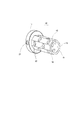
ところで、本実施形態のスリーブ10は、筒形状部12を周方向に360度回転させ、どの調整面161〜168であっても基準面33に当てた固定が可能になっている。この点、前記特許文献1の従来例では、偏芯スリーブの筒形状部に対し周方向に長い長孔が形成され、その長孔を通したボルトが工具ホルダに締め付けられている。しかし、従来例のスリーブでは、長孔が偏芯スリーブを90度回転させるだけの長さでしかなかった。そこで、本実施形態とは別に、360度の回転により芯高調整が可能な偏芯スリーブを提案する。図7は、偏芯スリーブの参考例を示した斜視図である。
<Reference example>
By the way, the
この偏芯スリーブ100は、フランジ部101と筒形状部102とを有し、筒形状部102の内径円の中心と外形円の中心とがずれている。そして、筒形状部102には軸方向の8箇所に、周方向に長い長孔121,122,131,132が形成されている。特に、この長孔121,122,131,132は、筒形状部102が周方向に360度回転した場合に、どの位置でも工具ホルダに固定できるようにしたものである。そのため、軸方向の位置が重なる2つずつの長孔121,122と長孔131,132とが各々一組となり、それぞれ周方向に90度分の長さを有し、90度ずれた位置に交互に形成されている。
The
一方、偏芯スリーブ100を装着する工具ホルダ2は、前記実施形態の工具ホルダ30のネジ孔24(図4参照)と同様に、4つのネジ孔が形成され、長孔121,122と長孔131,132に2つずつのネジ孔が対応している。従って、本参考例の偏芯スリーブ100は、筒形状部102を周方向に360度回転させ、どの回転角度であっても固定が可能である。
On the other hand, the
以上、本発明の部品回収装置の実施形態について説明したが、本発明はこれに限定されることなく、その趣旨を逸脱しない範囲で様々な変更が可能である。
例えば、前記実施形態では、切削工具6が挿入されたスリーブ10をボルト25によって工具ホルダ30に固定する構造としたが、調整面160を基準面33に当てた状態で位置決めできるのであれば、こうした構造に限るものではない。
また、軸心を有する切削工具6としてドリルを例に挙げて説明したが、そのほか中ぐりバイトなどであってもよい。
As mentioned above, although embodiment of the components collection | recovery apparatus of this invention was described, this invention is not limited to this, A various change is possible in the range which does not deviate from the meaning.
For example, in the above-described embodiment, the
Further, although the drill has been described as an example of the
1…タレット 2…工具ホルダ 6…切削工具 10…スリーブ 12…筒形状部 15…内側面 16…外側面 22…貫通孔 24…ネジ孔 30…工具ホルダ 33…基準面 160(161〜168)…調整面
DESCRIPTION OF
Claims (4)
前記スリーブは、円形断面からなる内側面と偶数の多角形断面からなる外側面とを有し、前記内側面を構成する円の中心から径方向に見て直行する前記外側面の複数の平面までの各々の距離が異なる調整距離として設定され、
前記工具ホルダは、前記スリーブの外側面のうち特定の平面が位置決め方向に当てられる基準面が前記装着部に設けられ、
前記切削工具が、前記特定の平面を前記工具ホルダの基準面に当てて位置決めされた状態の前記スリーブを介して前記刃物台に固定されるものであることを特徴とする切削工具の固定構造。 Fixing of a cutting tool in which a cylindrical sleeve is mounted on a mounting portion formed on the tool holder of the tool post, and a cutting tool having an axial center is fixed to the tool post in a state of being inserted into the sleeve. In structure
The sleeve has an inner surface having a circular cross section and an outer surface having an even polygonal cross section, and extends from a center of a circle constituting the inner surface to a plurality of planes of the outer surface that are perpendicular to the radial direction. Each distance is set as a different adjustment distance,
The tool holder is provided with a reference surface on the mounting portion on which a specific plane of the outer surface of the sleeve is applied in the positioning direction,
The cutting tool fixing structure, wherein the cutting tool is fixed to the tool post through the sleeve in a state where the specific plane is positioned with a reference surface of the tool holder applied thereto.
前記スリーブに設けられた複数の調整距離は、前記ズレ量が、ゼロ、前記許容値、そして前記許容値に当該許容値の倍数を整数倍して加算した値となることを特徴とする請求項2に記載する切削工具の固定構造。 In assembling the cutting tool, an allowable value is set for an assembling error which is a deviation amount between a center of a circle constituting the inner surface and a predetermined reference point,
The plurality of adjustment distances provided in the sleeve are characterized in that the deviation amount is zero, the allowable value, and a value obtained by adding a multiple of the allowable value to the allowable value by an integral multiple. The fixing structure of the cutting tool described in 2.
4. The sleeve according to claim 1, wherein a plurality of through-holes for allowing the screw member to pass therethrough are formed in each outer surface, and positions thereof are different when viewed from the adjacent outer surfaces. The cutting tool fixing structure described in any one of the above.
Priority Applications (1)
| Application Number | Priority Date | Filing Date | Title |
|---|---|---|---|
| JP2015031607A JP6431402B2 (en) | 2015-02-20 | 2015-02-20 | Cutting tool fixing structure |
Applications Claiming Priority (1)
| Application Number | Priority Date | Filing Date | Title |
|---|---|---|---|
| JP2015031607A JP6431402B2 (en) | 2015-02-20 | 2015-02-20 | Cutting tool fixing structure |
Publications (2)
| Publication Number | Publication Date |
|---|---|
| JP2016153148A JP2016153148A (en) | 2016-08-25 |
| JP6431402B2 true JP6431402B2 (en) | 2018-11-28 |
Family
ID=56760803
Family Applications (1)
| Application Number | Title | Priority Date | Filing Date |
|---|---|---|---|
| JP2015031607A Active JP6431402B2 (en) | 2015-02-20 | 2015-02-20 | Cutting tool fixing structure |
Country Status (1)
| Country | Link |
|---|---|
| JP (1) | JP6431402B2 (en) |
Family Cites Families (6)
| Publication number | Priority date | Publication date | Assignee | Title |
|---|---|---|---|---|
| JPS5251356Y2 (en) * | 1973-07-25 | 1977-11-21 | ||
| JPS5234495A (en) * | 1975-09-12 | 1977-03-16 | Nomura Takayuki | Main shaft moving type automatic lathe having cam settable at outside of machine |
| JPH0512010U (en) * | 1991-03-12 | 1993-02-19 | 三菱マテリアル株式会社 | Holder for boring bar |
| JP3029248U (en) * | 1996-02-26 | 1996-09-27 | 龍郎 合澤 | Holding device for cutting tools in lathes |
| FR2750905B1 (en) * | 1996-07-11 | 1998-09-18 | Snecma | TOOL AND METHOD FOR DEBURRING A DRILLING EDGE OPPOSED TO THE TOOL |
| US6145420A (en) * | 1999-01-28 | 2000-11-14 | Ehrlich; John D. | Turret lathe tool holder |
-
2015
- 2015-02-20 JP JP2015031607A patent/JP6431402B2/en active Active
Also Published As
| Publication number | Publication date |
|---|---|
| JP2016153148A (en) | 2016-08-25 |
Similar Documents
| Publication | Publication Date | Title |
|---|---|---|
| JP4833696B2 (en) | Work centering method and centering apparatus | |
| CN102785110B (en) | Center aligning method and standard ring | |
| JP2009541069A (en) | Spindle unit with a spindle that can be aligned during operation | |
| CN103894800A (en) | Candan universal joint fork processing method and fixture of candan universal joint fork | |
| CN207223456U (en) | A kind of pallet of processing space multi-hole position part | |
| CN108723414A (en) | Ensure the processing technology of numerically-controlled machine tool precision box parts main aperture system position of related features | |
| CN105904340B (en) | A kind of localization method of RV reducer shafts bearing hole grinding fixture and bearing saddle bore | |
| CN104646938B (en) | Microscope zoom compensation lens base machining method | |
| JP2020069602A (en) | Work-piece machining device | |
| KR101368761B1 (en) | Machining process of flange yoke | |
| CN101972861B (en) | Method for processing inclined hole on cylindrical surface of numerical control machine tool | |
| JP6431402B2 (en) | Cutting tool fixing structure | |
| JP5148333B2 (en) | Tool holder positioning device | |
| JP6999263B2 (en) | Manufacturing method and machine tool for multiple ball screws | |
| CN107538249A (en) | A kind of pallet of processing space multi-hole position part | |
| JP2006007397A (en) | Control method for positioning rotary table in machine tool and apparatus therefor | |
| WO2018198648A1 (en) | Scroll compressor manufacturing method | |
| JP6322498B2 (en) | Vertical lathe alignment system and method | |
| JP2017117282A (en) | Machine tool and control method of machine tool | |
| JP2009285783A (en) | Boring method of nc machine tool | |
| JP4763335B2 (en) | Simultaneous machining of workpieces with multiple tool posts | |
| JP2008119790A (en) | Tool holder and nc lathe on which the tool holder is mounted | |
| JP2007007811A (en) | Center | |
| US10293412B2 (en) | Chuck arrangement | |
| JP2016117125A (en) | Machine working jig |
Legal Events
| Date | Code | Title | Description |
|---|---|---|---|
| A621 | Written request for application examination |
Free format text: JAPANESE INTERMEDIATE CODE: A621 Effective date: 20180109 |
|
| TRDD | Decision of grant or rejection written | ||
| A977 | Report on retrieval |
Free format text: JAPANESE INTERMEDIATE CODE: A971007 Effective date: 20181010 |
|
| A01 | Written decision to grant a patent or to grant a registration (utility model) |
Free format text: JAPANESE INTERMEDIATE CODE: A01 Effective date: 20181023 |
|
| A61 | First payment of annual fees (during grant procedure) |
Free format text: JAPANESE INTERMEDIATE CODE: A61 Effective date: 20181102 |
|
| R150 | Certificate of patent or registration of utility model |
Ref document number: 6431402 Country of ref document: JP Free format text: JAPANESE INTERMEDIATE CODE: R150 |
|
| R250 | Receipt of annual fees |
Free format text: JAPANESE INTERMEDIATE CODE: R250 |
|
| R250 | Receipt of annual fees |
Free format text: JAPANESE INTERMEDIATE CODE: R250 |
|
| R250 | Receipt of annual fees |
Free format text: JAPANESE INTERMEDIATE CODE: R250 |