JP6431040B2 - Roll forming machine with reciprocating dies - Google Patents
Roll forming machine with reciprocating dies Download PDFInfo
- Publication number
- JP6431040B2 JP6431040B2 JP2016504308A JP2016504308A JP6431040B2 JP 6431040 B2 JP6431040 B2 JP 6431040B2 JP 2016504308 A JP2016504308 A JP 2016504308A JP 2016504308 A JP2016504308 A JP 2016504308A JP 6431040 B2 JP6431040 B2 JP 6431040B2
- Authority
- JP
- Japan
- Prior art keywords
- die
- blank
- reciprocating
- pattern
- pattern forming
- Prior art date
- Legal status (The legal status is an assumption and is not a legal conclusion. Google has not performed a legal analysis and makes no representation as to the accuracy of the status listed.)
- Active
Links
- 230000007246 mechanism Effects 0.000 claims description 55
- 238000000465 moulding Methods 0.000 claims description 53
- 238000013519 translation Methods 0.000 claims description 9
- 238000013459 approach Methods 0.000 claims description 2
- 238000000034 method Methods 0.000 description 42
- 230000008569 process Effects 0.000 description 42
- 238000005096 rolling process Methods 0.000 description 32
- 230000008901 benefit Effects 0.000 description 18
- 238000004519 manufacturing process Methods 0.000 description 13
- 238000003780 insertion Methods 0.000 description 11
- 230000037431 insertion Effects 0.000 description 11
- 230000033001 locomotion Effects 0.000 description 9
- 238000012546 transfer Methods 0.000 description 7
- 238000000059 patterning Methods 0.000 description 6
- 238000012545 processing Methods 0.000 description 6
- 230000002093 peripheral effect Effects 0.000 description 5
- 230000002441 reversible effect Effects 0.000 description 5
- 238000013461 design Methods 0.000 description 4
- 238000005516 engineering process Methods 0.000 description 4
- 239000012530 fluid Substances 0.000 description 4
- 238000012986 modification Methods 0.000 description 3
- 230000004048 modification Effects 0.000 description 3
- 230000003134 recirculating effect Effects 0.000 description 3
- 239000007787 solid Substances 0.000 description 3
- 230000007547 defect Effects 0.000 description 2
- 238000011161 development Methods 0.000 description 2
- 230000018109 developmental process Effects 0.000 description 2
- 230000005484 gravity Effects 0.000 description 2
- 230000006872 improvement Effects 0.000 description 2
- 230000000977 initiatory effect Effects 0.000 description 2
- 238000012423 maintenance Methods 0.000 description 2
- 230000008439 repair process Effects 0.000 description 2
- 239000007858 starting material Substances 0.000 description 2
- 229920000049 Carbon (fiber) Polymers 0.000 description 1
- ZOKIJEBQDZFGMW-PSXMRANNSA-N [(2R)-2-[12-(4-azido-2-nitroanilino)dodecanoyloxy]-3-tetradecanoyloxypropyl] 2-(trimethylazaniumyl)ethyl phosphate Chemical compound CCCCCCCCCCCCCC(=O)OC[C@H](COP([O-])(=O)OCC[N+](C)(C)C)OC(=O)CCCCCCCCCCCNc1ccc(cc1[N+]([O-])=O)N=[N+]=[N-] ZOKIJEBQDZFGMW-PSXMRANNSA-N 0.000 description 1
- 239000004917 carbon fiber Substances 0.000 description 1
- 230000008859 change Effects 0.000 description 1
- 238000010961 commercial manufacture process Methods 0.000 description 1
- 238000010835 comparative analysis Methods 0.000 description 1
- 238000004590 computer program Methods 0.000 description 1
- 239000002826 coolant Substances 0.000 description 1
- 230000008878 coupling Effects 0.000 description 1
- 238000010168 coupling process Methods 0.000 description 1
- 238000005859 coupling reaction Methods 0.000 description 1
- 229910001385 heavy metal Inorganic materials 0.000 description 1
- 238000007689 inspection Methods 0.000 description 1
- 238000009434 installation Methods 0.000 description 1
- 230000007774 longterm Effects 0.000 description 1
- 238000003754 machining Methods 0.000 description 1
- 230000007257 malfunction Effects 0.000 description 1
- 238000005259 measurement Methods 0.000 description 1
- VNWKTOKETHGBQD-UHFFFAOYSA-N methane Chemical compound C VNWKTOKETHGBQD-UHFFFAOYSA-N 0.000 description 1
- 238000012544 monitoring process Methods 0.000 description 1
- 238000011112 process operation Methods 0.000 description 1
- 238000009419 refurbishment Methods 0.000 description 1
- 230000007261 regionalization Effects 0.000 description 1
- 239000002904 solvent Substances 0.000 description 1
- 239000007921 spray Substances 0.000 description 1
- 230000001360 synchronised effect Effects 0.000 description 1
Images


Classifications
-
- B—PERFORMING OPERATIONS; TRANSPORTING
- B21—MECHANICAL METAL-WORKING WITHOUT ESSENTIALLY REMOVING MATERIAL; PUNCHING METAL
- B21H—MAKING PARTICULAR METAL OBJECTS BY ROLLING, e.g. SCREWS, WHEELS, RINGS, BARRELS, BALLS
- B21H3/00—Making helical bodies or bodies having parts of helical shape
- B21H3/02—Making helical bodies or bodies having parts of helical shape external screw-threads ; Making dies for thread rolling
- B21H3/06—Making by means of profiled members other than rolls, e.g. reciprocating flat dies or jaws, moved longitudinally or curvilinearly with respect to each other
-
- B—PERFORMING OPERATIONS; TRANSPORTING
- B21—MECHANICAL METAL-WORKING WITHOUT ESSENTIALLY REMOVING MATERIAL; PUNCHING METAL
- B21H—MAKING PARTICULAR METAL OBJECTS BY ROLLING, e.g. SCREWS, WHEELS, RINGS, BARRELS, BALLS
- B21H5/00—Making gear wheels, racks, spline shafts or worms
- B21H5/02—Making gear wheels, racks, spline shafts or worms with cylindrical outline, e.g. by means of die rolls
- B21H5/027—Making gear wheels, racks, spline shafts or worms with cylindrical outline, e.g. by means of die rolls by rolling using reciprocating flat dies, e.g. racks
-
- B—PERFORMING OPERATIONS; TRANSPORTING
- B21—MECHANICAL METAL-WORKING WITHOUT ESSENTIALLY REMOVING MATERIAL; PUNCHING METAL
- B21H—MAKING PARTICULAR METAL OBJECTS BY ROLLING, e.g. SCREWS, WHEELS, RINGS, BARRELS, BALLS
- B21H9/00—Feeding arrangements for rolling machines or apparatus manufacturing articles dealt with in this subclass
- B21H9/02—Feeding arrangements for rolling machines or apparatus manufacturing articles dealt with in this subclass for screw-rolling machines
Description
本開示は、対称往復ダイスを使用するロール成形パターン転造機に関する。更に、本開示は、ダイス面間に捕捉されているブランクであって、ダイス面間に捕捉されること以外では無支持状態であるブランクにパターンを転写する機構に関する。 The present disclosure relates to roll forming pattern rolling machines that use symmetrical reciprocating dies. Furthermore, the present disclosure relates to a mechanism for transferring a pattern to a blank that is captured between die surfaces that is unsupported except that it is captured between die surfaces.
[関連出願の相互参照]
本願は、米国特許法第119条(e)項に従い、2013年3月21日出願の米国仮特許出願第61/803855号「Roll Forming Machine With Reciprocating Dies(往復ダイスを備えるロール成形機)」の優先権を主張する。この米国仮特許出願の全内容は、本願と一体をなすものとして引用する。
[Cross-reference of related applications]
This application is subject to US provisional patent application No. 61/803855 “Roll Forming Machine With Reciprocating Dies” filed March 21, 2013, in accordance with section 119 (e) of the US Patent Act. Claim priority. The entire contents of this US provisional patent application are cited as being integral with the present application.
ねじや歯車の歯その他のパターンを円筒ブランクに対称往復ダイスを用いて冷間成形する技術は従来から知られている。特許文献1〜3に例示されている。このような機械は、意義がある長期の商業的成功を一切収めていない。一部のものは複雑で扱いにくい。 Techniques for cold forming screws, gear teeth and other patterns on a cylindrical blank using a symmetrical reciprocating die are conventionally known. It is illustrated by patent documents 1-3. Such machines have no significant long-term commercial success. Some are complex and unwieldy.
転造ねじ山を有するビスは、工業で幅広く使用されている。転造ねじ山を有するビスは、通常、長年にわたって存在する既知の平ダイス技術を用いて成形される。一般的に使用されている転造平ダイスは、対面関係に配置された、固定プラテン上の固定(短)ダイスと、往復スライド上の往復運動(長)ダイスとを含む。機械駆動部が可動ダイスを前進させてねじ山形状を作り出す。これらの機械は、信頼性はあるが、設定及び運用に熟練したオペレーターが必要である。現在最も一般的に使用されているねじ転造機は、ずっと以前に開発された技術に基づいており、重い金属部品が摩耗を受け、しばしば高価な修理が必要となる。 Screws with rolling threads are widely used in industry. Screws with rolling threads are usually formed using known flat die technology that has existed for many years. Commonly used rolling flat dies include a fixed (short) die on a fixed platen and a reciprocating (long) die on a reciprocating slide arranged in a face-to-face relationship. A mechanical drive advances the movable die to create a thread shape. These machines are reliable, but require an operator who is skilled in setting up and operating. Currently most commonly used thread rolling machines are based on technology that was developed a long time ago, heavy metal parts are subject to wear and often require expensive repairs.
更に、前述のねじ転造機は、ダイス面間でブランクを位置決めする挿入フィンガーを備え、可動ダイスを進めることでブランクを捕捉して直線運動させ、ダイス面を介してねじ山形状を転写するようになっている。ダイス面上のねじ成形パターンを、ダイス面間へのブランクの最初の挿入と同期させることは、ねじ成形の非常に重要な局面である。用いる機械は、種々の調整部材を備え、これらの非常に重要な関係の精密調整を可能にする。 Furthermore, the aforementioned thread rolling machine is provided with an insertion finger for positioning the blank between the die surfaces, and by moving the movable die forward, the blank is captured and linearly moved, and the thread shape is transferred via the die surface. It has become. Synchronizing the thread forming pattern on the die face with the initial insertion of the blank between the die faces is a very important aspect of thread forming. The machine used is equipped with various adjustment members, allowing fine adjustment of these very important relationships.
挿入フィンガーの機構は、現行のねじ成形装置の主要な要素に相当する。機械保守、並びにこれらの部品の修理及び交換は、商業締結具製造の総コストを著しく増加させる。 The mechanism of the insertion finger corresponds to the main element of the current thread forming device. Machine maintenance and the repair and replacement of these parts significantly increase the total cost of commercial fastener manufacturing.
本開示は、サーボモーター、ベルト駆動部、再循環式軸受上で動作する軽量スライド、及び対称往復ダイス等の現在利用可能な技術の態様を用いる、進歩的な設計の冷間成形装置に関する。開示される装置の実施態様は、ねじ締結具、及び他の同様に製造される円筒のパターン付き製品の冷間成形に変革を起こすであろう。 The present disclosure relates to an advanced design cold forming apparatus using aspects of currently available technology such as servo motors, belt drives, lightweight slides operating on recirculating bearings, and symmetrical reciprocating dies. Embodiments of the disclosed apparatus will revolutionize the cold forming of threaded fasteners and other similarly manufactured cylindrical patterned products.
本明細書に開示される転造機は、往復運動する対称平型工具を用いて、円筒ブランクにパターンを成形する。ねじ成形機として示されているが、開示される原理は、円筒ブランク上へのいかなるパターンの成形にも適用可能である。 The rolling machine disclosed in this specification forms a pattern on a cylindrical blank using a symmetrical flat tool that reciprocates. Although shown as a screw forming machine, the disclosed principles are applicable to forming any pattern on a cylindrical blank.
上記代表的な実施形態では、ダイス面は、ダイス間で転動する円筒ブランク上にねじを成形するようにねじパターンを有して構成される。対称型工具の使用により、双方のダイスが同時に動くことが可能になり、これにより、ブランクをねじ山形状にする処理を完了するサイクル時間が減少する。更に、ブランクが2つの可動ダイス間で転動する場合、ブランクは、固定位置においてブランク自体の長手の中心軸線の回りに回転する。ブランクがその固定位置にとどまらないことは、位置ずれの可能性を示す。これは、ブランクが固定ダイスの面を横切って動く既知のプロセスでは検知することができないサインである。 In the above exemplary embodiment, the die surface is configured with a screw pattern so as to form a screw on a cylindrical blank that rolls between the dies. The use of a symmetric tool allows both dies to move simultaneously, which reduces the cycle time to complete the process of threading the blank. Furthermore, when the blank rolls between two movable dies, the blank rotates around the longitudinal central axis of the blank itself in a fixed position. The fact that the blank does not stay in its fixed position indicates the possibility of misalignment. This is a sign that cannot be detected by known processes in which the blank moves across the surface of the fixed die.
本開示の構成は、ねじ締結具等の円筒のパターン付き製品の首尾良い商業製造において一般的に用いられている方法及び現用されている装置とはかなり異なる。ここでは、プロセスは、平行な経路に沿って往復する2つの同一のねじ成形ダイスを使用する。各ダイス面の輪郭は、ブランクとの作用的な接触及び漸進的なねじ成形を確実にするのに必要な形状を有する。重要なことに、対称往復ダイスの構成によって、ブランク挿入機構の使用が可能になり、ブランク挿入機構によって、スタータフィンガーの必要性と、複雑なダイスのタイミング調整、スタータフィンガーの挿入ストローク、及び関連する難題とが排除される。 The configuration of the present disclosure differs significantly from the methods and devices currently used in the successful commercial manufacture of cylindrically patterned products such as screw fasteners. Here, the process uses two identical threading dies that reciprocate along parallel paths. The profile of each die surface has the shape necessary to ensure active contact with the blank and gradual threading. Importantly, the configuration of the symmetrical reciprocating die allows the use of a blank insertion mechanism, which allows for the need for starter fingers, complex die timing adjustment, starter finger insertion strokes, and related Difficult problems are eliminated.
ここで、本開示は、円筒パターン受け面を有するブランクの円筒面上にパターンを成形する往復ダイスパターン成形機が、基台と、前記基台上で相対するとともに、長手方向平面に対して平行かつ該長手方向平面の両側にある経路に沿って可動である、一対の摺動部材と、前縁部及び後縁部と、パターン成形面とをそれぞれ有し、対面関係で前記摺動部材上に搭載される、少なくとも一対のパターン成形ダイスと、前記ダイスの前記前縁部が前記円筒パターン受け面の前記直径よりも大きい距離だけ離間しているとき、前記ダイスの前記前縁部間にブランクを給送、位置決めする機構と、完全後退位置と完全挿入位置との間で前記ダイスを往復運動させる、前記摺動部材の駆動機構とを備え、前記ダイスの前記パターン成形面は、前記位置決めされたブランクの前記円筒パターン受け面の正対する面において、該円筒パターン受け面に同時に係合するように構成されており、前記完全後退位置から前記完全挿入位置への前記ダイスの軸方向並進により、前記ブランクが、前記パターン成形面間で該ブランクの長手方向中心の回りに回転し、前記円筒パターン受け面上に前記パターンを転写し、前記ダイスは、前記完全挿入位置に向かう前記ダイスの軸方向並進中、前記ブランクを支持するように構成されている、往復ダイスパターン成形機を含む。 Here, in the present disclosure, a reciprocating die pattern forming machine that forms a pattern on a cylindrical surface of a blank having a cylindrical pattern receiving surface is opposed to the base on the base and parallel to the longitudinal plane. And a pair of sliding members that are movable along a path on both sides of the longitudinal plane, a front edge portion and a rear edge portion, and a pattern forming surface, respectively, on the sliding member in a face-to-face relationship. When at least a pair of pattern forming dies mounted on the die and the front edge portion of the die are separated by a distance larger than the diameter of the cylindrical pattern receiving surface, a blank is provided between the front edge portions of the die. A mechanism for feeding and positioning, and a drive mechanism for the sliding member for reciprocating the die between a fully retracted position and a fully inserted position, and the pattern forming surface of the die is positioned by the positioning. The cylindrical blank receiving surface of the blank is configured to be engaged with the cylindrical pattern receiving surface at the same time, by axial translation of the die from the fully retracted position to the fully inserted position. The blank rotates about the longitudinal center of the blank between the pattern forming surfaces, transfers the pattern onto the cylindrical pattern receiving surface, and the die shafts the die toward the fully inserted position. A reciprocating die patterning machine configured to support the blank during directional translation is included.
これに関して、円筒パターン受け面を有するブランクにパターンを成形する方法において、前縁部及び後縁部と、パターン成形面とをそれぞれ有し、対面関係で搭載されて、長手方向平面の両側において完全後退位置と完全挿入位置との間で相互運動する、一対のパターン成形ダイスを準備することと、前記長手方向平面において、前記ダイスの前記前縁部から等距離で、前記ブランクの前記円筒パターン受け面の前記長手方向中心を位置決めすることと、前記ダイスの前記パターン成形面を、前記円筒パターン受け面の正対する面において、該ブランクの該円筒パターン受け面と同時に係合させることと、前記ダイスを前記完全挿入位置に向かって軸方向に並進させて、前記ブランクを該ブランクの長手方向中心の回りに回転させ、前記ブランクの前記円筒パターン受け面上に前記パターンを転写することと、前記ダイスの前記軸方向並進中、前記ダイスの前記パターン成形面を前記ブランクの前記パターン受け面と係合させることにより、前記ブランクを支持することとを含む方法が開示される。 In this regard, in a method of forming a pattern on a blank having a cylindrical pattern receiving surface, each has a leading edge portion, a trailing edge portion, and a pattern forming surface, mounted in a face-to-face relationship, and completely on both sides of the longitudinal plane Providing a pair of patterning dies that move relative to each other between a retracted position and a fully inserted position; and in the longitudinal plane, equidistant from the leading edge of the die, the cylindrical pattern receiver of the blank Positioning the longitudinal center of a surface, engaging the pattern forming surface of the die simultaneously with the cylindrical pattern receiving surface of the blank on a surface facing the cylindrical pattern receiving surface; Is translated axially toward the fully inserted position and the blank is rotated about the longitudinal center of the blank so that the The blank by transferring the pattern onto the cylindrical pattern receiving surface of the die and engaging the pattern forming surface of the die with the pattern receiving surface of the blank during the axial translation of the die. Is disclosed.
本開示は、円筒ブランクの外面上にねじ山形状等のパターンを成形する往復ダイスロール成形機を含むとともに、適所で回転するブランクに作用する、少なくとも一組の往復ダイスを含む。この成形機は、中央処理装置によって制御されるサーボモーターによりベルト駆動されるダイスを支持する、スライドと軸受との組合体を備える。ダイスが係合するように、ブランクを給送、位置決めする機構が設けられる。1つの形態において、この成形機は、複数のダイス組を備え、ダイスの1往復運動サイクル中に複数の部品を製造する。別の形態において、この成形機は、別個の複数の駆動機構を使用し、ダイス組の各ダイスを独立して駆動する。 The present disclosure includes a reciprocating die roll forming machine that forms a thread-like pattern on the outer surface of a cylindrical blank and includes at least one set of reciprocating dies that act on the blank rotating in place. The molding machine includes a combination of a slide and a bearing that supports a die that is belt-driven by a servomotor controlled by a central processing unit. A mechanism is provided for feeding and positioning the blank so that the dies engage. In one form, the molding machine includes a plurality of die sets and produces a plurality of parts during one reciprocating cycle of the dies. In another form, the molding machine uses a plurality of separate drive mechanisms to drive each die of the die set independently.
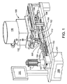
図1を参照すると、本開示の往復ダイスロール成形機100が斜視図で示す。明確さのために、添付図面に200で示す細長いブランクから小ねじを形成することに関連してロール成形機およびその作用を説明する。これらの図面では、記載の明確さのために、ブランク200の頭部は省略されており、ねじ加工される円筒外面を有する軸部のみが図示されている。しかし、ここに開示するロール成形機及びその部品は、どのようなパターンを円筒ブランク上に成形する場合にも用いることができる。
Referring to FIG. 1, a reciprocating die
成形機100は、基台101上に支持される一対の細長い固定レール102を備える。各レールは、再循環ボール軸受を備えた往復スライドブロック104を支持する。スライド104は、成形ダイス112をそれぞれ保持する。とりわけ、スライド104及びレール102は、ねじ転造中のブランクの変形に伴う側方または横断方向の負荷を受けるように十分なサイズである。
The
スライド104は、一対の歯付きベルトセグメント105、106によって、レール102上で往復運動するように連結されている。セグメント105は、基台101上に搭載される可逆サーボモーター110によって駆動される歯付きピニオン107の周囲を移動する。セグメント106は、基台101上で回転可能に支持されるアイドラプーリー108を巡って延設されている。サーボモーター110の順回転及び逆回転すると、ベルトセグメント105、106により、往復スライド104がレール104上のを軸方向に移動する。サーボモーター110の動作は、オペレータータッチスクリーンパネル111からの命令を受けるソフトウェアに応答する中央処理装置(CPU)109によって制御される。
The
オペレーターステーション111からの入力は、ブランク上への成形がプロセス作業中心において開始することを保証するように、必要に応じてスライド104(つまりダイス112)を位置決めすることができる。ダイスが、成形されるブランク及び互いに対して適切に位置合わせされている場合、ブランクの外面上に所望のパターンが転写される。入力制御装置は、往復スライド104の経路長を設定すること、及び成形機の全ての他の機能を制御することもできる。
Input from the
可逆サーボモーター110は、駆動力を提供する。とりわけ、成形機100の構成は、スライド104を運動させるのにベルト105、106の手動操作を用いることができるようになっている。サーボモーター110は、このようなことに融通が利く。また、単一の成形機が、レール102に沿ってサーボモーター110によって同時動作されるように連結されている、複数のダイス組を伴う複数のスライドブロックを備えてもよいことが考慮される。このような構成では、複数の部品を同時に成形することができる。
The
本開示では、「長手方向」と言及する場合、可動ダイスの移動経路に沿うことを意味する。「横断方向」と言及する場合、ダイスの作業面に対して垂直であることを意味する。「前方」と言及する場合、長手方向におけるねじ転造方向であることを意味し、「後方」と言及する場合、その反対方向を意味する。 In the present disclosure, when referring to the “longitudinal direction”, it means along the moving path of the movable die. When referring to the “transverse direction”, it means perpendicular to the working surface of the die. When referring to “front”, it means the direction of thread rolling in the longitudinal direction, and when referring to “backward”, it means the opposite direction.
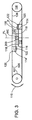
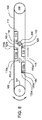
図2、4は、円筒ブランク上に螺旋ねじ(又は他の所望のパターン)を転造するように配置されている、本開示の一組の対称往復ダイスの構成を概略的に示している。開示される構成は、当然ながら、円筒ブランクの外面上に任意の繰返しパターンを冷間成形するのに好適である。 2 and 4 schematically illustrate the configuration of a set of symmetrical reciprocating dies of the present disclosure that are arranged to roll a helical screw (or other desired pattern) onto a cylindrical blank. The disclosed arrangement is of course suitable for cold forming any repeating pattern on the outer surface of a cylindrical blank.
112で示すダイスが、成形機100の、レール102上で長手方向に移動するスライド104上に搭載され、図2に示す完全後退位置、すなわち装填位置と、図4に示す完全挿入位置、すなわち解放位置との間で往復運動する。
A die indicated by 112 is mounted on a
後方移動限界(後退位置)において、ダイス112の前縁部114は、円筒ブランク200を前縁部間の空間に挿入するのに十分な距離だけ離間している。ダイスの完全挿入位置において、ダイスの後縁部116は、互いを通り越して、成形済み部品を解放するのに十分な距離だけ離間している。したがって、各ダイスの移動経路長は、ダイスのそれぞれの長手方向長さをいくらか上回る。なお、図示の往復ダイスは、鉛直方向に向き付けられている。ブランクは、その長手の中心軸線が垂直方向に配された状態で同様に位置決めされる。この向きは、往復ダイス112間での、ブランクの装填に向けた垂直方向における送給及び解放に適している。また、水平方向等のダイスの他の向きを用いてもよい。
At the rearward limit (retracted position), the
ブランクに転写されるパターンを有するダイス面118は、対面関係にあり、鉛直方向の長手方向平面Pから等距離かつ長手方向平面Pの両側において、後退位置と挿入位置との間での平行な往復運動経路を往来する。ダイス面118は、ねじ成形山のパターンを有し、ブランク200の円筒外面にねじ山形状を転写する。ダイス面118は、対面関係に位置決めされ、各ダイス上の成形パターンが、差し挟まれたブランク200の外面に係合するように、或る距離だけ離間している。成形プロセスの「作業中心」が、平面Pにあり、図面ではWCで示す。「作業中心」は、ダイス112の前縁部114から、つまりダイス面パターンから等距離で横断方向平面PLの交差点に配置されている。
The
ビスを作製する通常のダイスは、一定の断面、すなわち一定の機械加工ねじ深さを有して設計される。正確に成形するために、マシン設定オペレーターは、成形機においてダイスを角度付けるように調整を行わなければならない。これにより、ブランクがダイス面全体に亘って徐々に成形されることが可能になる。この理由から、オペレーターが異なると、オペレーターの設定経験に応じてダイスの寿命が異なってくる。ここで、必要に応じて、ねじパターンが平面Pに向かって前縁部114から後縁部116にかけて収束するようにダイス面を形成してもよい。すなわち、各ダイス面上のねじ山形状、すなわちねじパターンは、前縁部114から後縁部116にかけて或る角度で平面「P」に向かって収束するように形成され、そのため、ブランクの変形は、前縁部から後縁部にかけて増加する。各ダイスの、その前縁部114と後縁部116との間の長さは、ブランク200が、移動するダイス面間で転動する際に4回転〜5回転を完了するのに十分である。
Conventional dies for making screws are designed with a constant cross-section, i.e. a constant machined screw depth. In order to form accurately, the machine setting operator must make adjustments to angle the dies on the forming machine. This allows the blank to be formed gradually over the entire die surface. For this reason, different operators have different die lifespans depending on the operator's setting experience. Here, if necessary, the die surface may be formed so that the screw pattern converges from the
代替的には、他の既知のロール成形機におけるように、ダイスが一定の機械加工深さを有して作製されることが考慮される。長手方向平面Pに向かって前縁部114から後縁部116にかけて必要なダイス面118の収束は、各ダイスの後面と、各ダイスの連係する摺動可能軸受ブロック104との間にシムを配置することによって達成される。ダイスの製造及び設置のこれらの代替的な形態は、本開示の全ての実施形態において使用されるダイスに用いることができる。
Alternatively, it is considered that the dies are made with a constant machining depth, as in other known roll forming machines. The necessary convergence of the
図2のねじ加工される円筒ブランク200は、各ダイス面118の前縁部114から等距離で、その長手方向中心線がプロセス作業中心WCにある状態で位置決めされる。ダイスが完全後退位置から完全挿入位置に向かって進むと、前縁部114にあるダイス面パターンが、プロセス作業中心WCを通過する長手方向平面Pに対して垂直な横断方向接触平面「PL」に沿って正対する面において、ブランクに同時に係合する。
The cylindrical blank 200 to be threaded in FIG. 2 is positioned at an equal distance from the
ダイス面上のねじ成形パターンは、ダイス面上のパターンが、他方のダイス面に対して180度変位しているように向き付けられる。この関係は、当然ながら、ブランクに適切な変形を転写するのに必要である。 The thread forming pattern on the die surface is oriented so that the pattern on the die surface is displaced 180 degrees relative to the other die surface. This relationship is of course necessary to transfer the appropriate deformation to the blank.
適切に位置合わせされた関係では、ブランク200は、プロセス作業中心WCにおいて、ブランクの長手方向中心の回りに回転し、長手方向平面Pに対して長手方向に固定したままである。ねじパターンの転造中、ブランクが長手方向に動く場合、それは、不具合があること及び不満足な結果が起こることを示している。 In a properly aligned relationship, the blank 200 rotates about the longitudinal center of the blank at the process work center WC and remains longitudinally fixed with respect to the longitudinal plane P. If the blank moves in the longitudinal direction during rolling of the screw pattern, it indicates that there are defects and unsatisfactory results.
図2に概略的に示すように、ダイス112が完全後退位置にあるとき、前縁部114は、成形されるブランクの直径よりも大きい距離だけ離間している。ダイスの前縁部114が横断方向平面CLにおいてブランクの円筒外面と接触するまで、ブランク200を適所に位置決め及び保持するために、各ダイス112には、前縁部114の長手方向前方に支持ブロック120が設けられる。支持ブロック120は、図6に示す。支持ブロック120は、所与のブランク(長さ及び直径)と協働し、ブランクが往復ダイス112の面118間で前縁部114において捕捉される前は、ブランクを支持するように構成されている。これに関して、各支持ブロック120は、ブロック120間に配置されるブランクが、ダイス面118の上縁部の下方に位置決めされた成形される面全体と当接するように、各ダイス112の頂部に対して有る深さに位置決めされている、水平方向停止面122を有する。これは、通常は軸部上方に拡径した頭部を有するビスを成形する際に特に重要である。
As shown schematically in FIG. 2, when the
図2、4に示すように、水平方向停止面122は、平面Pに向かって、ブランク200を支持するのに十分な或る距離だけ横断方向内方に延出しているが、成形動作中に互いを通過するのに十分離間している。また、支持ブロック120は、平面Pに向き、つまり互いに向き合う鉛直方向ガイド面124をそれぞれ有する。面124は、鉛直方向に向き付けられたブランクを受け取るのに十分離間しており、また、そのブランクの長手方向中心を、各ダイス面118から等距離で平面Pと位置合わせして維持する。したがって、ブランク200が(重力により)支持ブロック120間に挿入されることが可能である場合、ブランク200は、鉛直方向では水平方向停止面122によって位置決めされ、また横断方向では鉛直方向ガイド面124によって位置決めされ、ダイス118がブランクの外面と係合することによる成形動作の開始が、ブランクがダイス面118及び平面Pに対して適切に向き付けられた状態で起こるようになっている。ダイス112の前縁部114に対するブランクの最終的な向き付けは、以下で詳細に説明されるブランク送給機構300がブランクに係合する際に行われる。
As shown in FIGS. 2 and 4, the
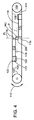
図3に示すように、ダイス112が平面Pによって規定される経路に沿って互いに向かって移動すると、ダイスブランク200は、ダイス間に捕捉及び支持される。ブランク200が双方のダイスに接触すると、ブランクの外面が双方のダイス面118と接触することで、ブランクがその長手方向中心の回りに回転を開始する。
As shown in FIG. 3, as the dies 112 move toward each other along the path defined by the plane P, the
ダイス112が完全挿入位置に向かって動き続けると、ダイス面は、平面P上で互いを通過する。ブランクは、ダイスがその外周面に係合すると、その鉛直方向中心の回りに回転しながら固定位置にとどまる。ねじ成形ダイスは、ブランク200の周面を変形させ、ねじパターンを成形する。このダイス112間の進行状況を図3に示す。
As the dies 112 continue to move toward the fully inserted position, the die surfaces pass each other on the plane P. The blank remains in a fixed position while rotating about its vertical center when the die engages its outer peripheral surface. The screw forming die deforms the peripheral surface of the blank 200 to form a screw pattern. The progress between the
図4は、成形機100のねじ成形プロセスの終結部を示している。ここで、転造ダイス112は、平面Pに沿ったその相対経路の前方終端まで移動している。ダイスの間隔は、ダイス面118が、ここで完成したねじ締結具(元はブランク200)の外周面から離間するようなものである。ねじ締結具は、自由になって、適切な収集容器(図示せず)内に落下する。
FIG. 4 shows an end part of the thread forming process of the
本明細書に開示される機構の開発時、いくつかの要因が、満足にロール成形されたねじの生成にとって非常に重要であると判断された。ブランクは、ブランクの長手方向中心が成形機の作業中心WCと同軸である状態で、作業中心WCに配置されなければならないことが重要である。ダイスは双方とも、平面PLにおいて180度離れた面においてブランクに係合し、180度離れた2つの正対するブランクとの接触線上でのパターン成形を適切に同期しなければならない。 During the development of the mechanism disclosed herein, several factors were determined to be very important for the production of satisfactorily rolled screws. It is important that the blank must be placed at the work center WC with the longitudinal center of the blank being coaxial with the work center WC of the molding machine. Both dies must engage the blank at a plane 180 degrees apart in the plane PL, and properly synchronize the patterning on the contact line with two opposing blanks 180 degrees apart.
図1に示すように、成形機100は、ダイス112の上縁部の上方にプロセス作業中心WC(図2〜図4)と位置合わせして支持されている鉛直方向供給管132を有する、ブランク供給容器130を備える。成形されるブランク200は、管132内で鉛直方向に互いに重なってスタックされ、ここから、ダイスの1往復運動サイクルごとに1つの成形されるブランク200が、ダイス面118による成形位置に落下する。
As shown in FIG. 1, the
図5は、鉛直方向供給管132の下端部を示している。この下端部は、図2〜図4の横断方向接触平面PL上で180度離れて位置決めされている、2つのスロット134を有する。スロット134は、以下で説明される目的で管132に対して位置決めされているブランク200へのアクセスを許可する。
FIG. 5 shows the lower end of the
成形機100は、図1に示すブランク給送位置決め機構300を備える。図5〜図7にブランク給送位置決め機構を更に詳細に示す。ブランク給送位置決め機構は、往復スライド104の上方に支持される。機構300は、マシンサイクルごとに、供給管132内にスタックされているブランクに作用し、ダイス112間でのロール成形に向けて単一のブランクを給送する。マシンサイクルとは、ダイス112を完全後退位置(図2)から完全挿入位置(図4)に、また戻って完全後退位置(図2)に運ぶ、スライド104の完全な1往復である。ブランク給送位置決め機構300は、サイクルの最初の部分中、各サイクル中の処理に向けて1つのブランク200を給送、位置決めするように動作する。
The
給送位置決め機構300は、ソレノイドによって作動する。給送位置決め機構の機能及びタイミングは、CPU(コンピューター)109及び連動するソフトウェアによって協調し、スライド104及びダイス112の往復運動を同期させる。
The
給送位置決め機構300は、鉛直方向供給管132のスロット134と位置合わせされているキャッチフィンガー304を有する、一対の横断方向アーム302を含む。横断方向アーム302は、キャッチフィンガー304がダイス112の頂部の上方に位置決めされている状態で、機構300上で枢動するように支持されている。横断方向アーム302は、通常、管132の底端部においてブランク200を保持するように互いに向かって付勢され、ブランク200が管(図7を参照)を出るのを防止する。横断方向キャッチフィンガー304は、スロット134に進入し、管132内の一番下のブランク200の鉛直方向円筒面と端部が接触する。
The
また、ブランク給送位置決め機構300は、対面する位置決めフィンガー312を有する、一対の位置決めアーム310を含む。位置決めアーム310は、機構300上で枢動するように支持され、位置決めフィンガー312を長手方向平面Pに沿って互いに接近、離反するように動かす。位置決めアーム310は、通常の開位置、すなわち拡開位置に付勢してもよい。位置決めフィンガー312の自由端313は、ブランク200の円筒外面の直径よりも大きい距離だけ離間しており、またブランクの円筒外面と協働するように曲面を有する。とりわけ、図6又は図7に示すように、位置決めフィンガー312及び対面端313は、ダイス112及び支持ブロック120の頂面の下方で機能する。したがって、位置決めアーム310及び位置決めフィンガー312の厚さは、支持ブロック120の鉛直方向ガイド面124と、ダイス112の面118との間の横断方向間隔よりも小さくなければならない。
The blank
ブランク給送位置決めシステムの一連の動作は以下のとおりである。このとき、ダイスの前縁部114がブランク200を受け取るのに十分離間しているダイスの往復運動サイクルの部分中(図2)、ブランク給送が行われることが認識される。とりわけ、サイクルのこの部分中、支持ブロック120は、プロセス作業中心WCに隣接して位置決めされ、給送されるブランク200を受け取って支持する。
A series of operations of the blank feed positioning system is as follows. At this time, it will be appreciated that blank feeding occurs during the portion of the die reciprocating cycle in which the
ブランク200の給送は、鉛直方向供給管132内のブランクの鉛直方向スタックにおける一番下のブランク200の解放によって開始する。これは、横断方向アーム302を、鉛直方向供給管132の底端部にあるスロット134から、キャッチフィンガー304を瞬間的に引き抜くように作動されることで行われる。ブランク200は解放されて、支持ブロック120の鉛直方向ガイド面124間で鉛直方向に落下する。このような鉛直方向の降下は、ブランク200の底部が支持ブロック120の水平方向停止面122と接触することにより制限される。この関係は、図6、7に示す。横断方向アーム302は、通常の閉位置をとることが即座に可能になる。すなわち、このとき、キャッチフィンガー304の対面端が鉛直方向供給管132のスロット134内にあり、次のブランク200を捕捉して、ブランクのコラムの残りを支持する。
キャッチフィンガー304から解放されたブランク200は、鉛直方向ガイド面124間で落下し、位置決めフィンガー312の対面曲面端313間の水平方向停止面122に載る。機構300は、位置決めアーム310を即座に作動し、互いに向かって枢動させる。位置決めフィンガー312の端313の曲面は、互いに向かって動き、ブランク200の円筒外面に係合する。位置決めアーム310によるこのような動作により、ブランク200の長手方向中心線がプロセス作業中心WCと位置合わせされている状態で、ブランクがプロセス作業中心WCに位置決めされる。
The blank 200 released from the
位置決めフィンガー312は、ダイス112の前縁部114が、横断方向接触平面PLにおいて180度(正対して)離れた接触線においてブランクの円筒外面に係合するまで、ブランクを適所に瞬間的に維持する。ダイス112の前縁部114においてこのような係合が起こると、位置決めフィンガー312がブランク200を解放する。すなわち、位置決めアーム310は、端313をブランク200から離してブランク200と接触しない状態に動かすように作動される。ブランクは、鉛直方向では水平方向停止面122によって、横断方向では鉛直方向ガイド面124によって、また長手方向では位置決めフィンガー312の対面曲面端313によって位置決めされる。ブランクは、ダイス112の対向面118の前縁部114によって把持され、プロセス作業中心WCの回りに自由に回転し、この際、ダイスが完全挿入位置(図4)に向かって動かされると、ダイス112の面118上のパターンがブランクの両側を通過する。ダイス112が完全挿入位置(図4)に達すると、後縁部116は、成形済み部品を解放するのに十分離間し、成形済み部品は、プロセス作業中心WCと鉛直方向に位置合わせされた状態で、レール102の下方に位置決めされている、図7に示すレセプタクル315に落下する。
Positioning
成形ダイス112と接触させるようにブランク200を位置決めすることは、円筒外面上での満足なパターンの首尾良い成形にとって非常に重要であることは明らかである。ブランク200は、ダイス面パターンを同期した状態で、前縁部114がブランクの対向面に接触するように位置決めされなければならない。また、ブランクは、鉛直方向においてダイス間に完全に挿入されなければならず、ブランクは、完全なブランクを満足なパターンを有する状態で形成するためには鉛直方向に配置されなければならない。その目的で、成形機の動作を制御するようにマシンビジョン装置を使用してもよいことがわかっている。マシンビジョンは、カメラ技術及び比較解析を使用して製造装置の動作を評価する既知の技術である。カメラ信号が異常を認識する場合、連動するコンピューターが、不具合を示す出力信号を与える。マシンビジョン装置は、調整のために装置を停止すること及び製造ラインに不満足な製品が入り込むことを防止することにも用いることができる。
Obviously, positioning the blank 200 in contact with the forming
単一のダイスにではなく、双方のダイスに往復運動の動作を用いるねじ転造機には、いくつかの利点がある。フライホイール及びクランクシャフトを介して駆動する標準的な電気モーターを用いるのではなく、逆回転してダイスを戻すサーボモーターを使用する場合、更なる利益がある。 A thread rolling machine that uses reciprocating motion on both dies rather than on a single die has several advantages. There is an additional benefit when using a servo motor that rotates in reverse and returns the die, rather than using a standard electric motor driven through a flywheel and crankshaft.
第1に、ロール成形の既知の局面である転動径を測定して知ることができることである。2つのねじ転造ダイス間でブランクが回転するのに接する直径は、仕上がった部品の外径又はブランクの最小径と等しくない。この直径は、仕上がった部品の外径とブランクの最小径との間のどこかの数値と等しく、すなわちこれが転動径である。 First, it can be known by measuring the rolling diameter, which is a known aspect of roll forming. The diameter in contact with the blank rotating between the two thread rolling dies is not equal to the outer diameter of the finished part or the minimum diameter of the blank. This diameter is equal to some value between the outer diameter of the finished part and the minimum diameter of the blank, ie this is the rolling diameter.
転動径は、ダイスの表面とブランクの面との間の摩擦に起因して生じる。この摩擦は、ブランクを、2つのダイス面間で摺動ではなく回転させる。ブランクの特性は、通常ねじとして形状付けられる2つの寸法断面である。圧力、幾何形状、面仕上げ、設定圧力、及び総摩擦力が転動径を変動させる。ダイス設計者は、あらゆる設定が現在の商業装置に固有になされるため、これらの変数を全ては掌握しない。 The rolling diameter is caused by friction between the surface of the die and the surface of the blank. This friction causes the blank to rotate rather than slide between the two die surfaces. The properties of the blank are two dimensional cross sections, usually shaped as a screw. Pressure, geometry, surface finish, set pressure, and total friction force vary the rolling diameter. Dice designers do not have all of these variables because every setting is specific to current commercial equipment.
サーボ制御によって成形機のスライドを正確な距離だけ動かすことができることにより、ビスの転動径を確定することが可能になる。本開示のサーボ駆動式のねじ転造機は、転造プロセスを開始し、次に精密な量だけ動くことを可能にする。監視目的で、プロセスが一時停止した時点でブランクの角度位置を記録することが可能である。したがって、ダイスは、ねじ転造ダイスの「横断方向ピッチ」において設計される精密な距離だけ動き、ブランクは精密に360度回転するものとする。 Since the slide of the molding machine can be moved by an accurate distance by servo control, the rolling diameter of the screw can be determined. The servo-driven screw rolling machine of the present disclosure allows a rolling process to be initiated and then moved by a precise amount. For monitoring purposes, the angular position of the blank can be recorded when the process is paused. Thus, it is assumed that the die moves by a precise distance designed in the “crosswise pitch” of the thread rolling die and the blank is precisely rotated 360 degrees.
全てのねじ転造ダイスは、ブランクを4回転〜6回転だけ回転させることが一般的である。記録された角回転が360度でない場合、ダイスに対して調整を行い、また測定して精密な横断方向ピッチを知ることができる。この調整が行われると、工具は、より長い寿命でより効率的に機能する。サーボモーターを使用しなければ、記載した測定を行うために、非常に複雑な補助システムが適所に必要となる。サーボ駆動を伴う開示される成形機は、ダイス設計に対するフィードバックを実際に与える。 All thread rolling dies typically rotate the blank 4 to 6 revolutions. If the recorded angular rotation is not 360 degrees, the die can be adjusted and measured to know the precise transverse pitch. When this adjustment is made, the tool functions more efficiently with a longer life. Without a servo motor, a very complex auxiliary system is needed in place to make the described measurements. The disclosed molding machine with servo drive actually provides feedback for die design.
本開示のねじ転造機の別の利益は、再循環式リニア軸受の使用である。このような軸受は、高い耐久性に製造され、長期間に亘る高負荷に耐えることが可能である。M6ビスを製造するのに用いられるそのような機械は、保守が必要となるまでに4年間、1日24時間250ストローク/分でビスを製造することが可能であることが想定される。更に、そのような軸受は、単純な工具を用いて低コストかつ最小のダウンタイム時間で容易に交換することができる。現行のねじ成形機案内面(スライド)は、熟練した専門家によって改修されなければならず、これには分割で数千ドルと、労働力と、未知のダウンタイムとが伴う。いくつかの例において、現行の機械は、工場から実際に移動し、改修に向けて修理業者のところまで輸送しなければならない。更に、高速ころ軸受は、従来の油膜式案内面を用いるよりもはるかに堅牢であり、そのため設定を極めて一貫させることができる。 Another benefit of the thread rolling machine of the present disclosure is the use of recirculating linear bearings. Such a bearing is manufactured with high durability and can withstand high loads over a long period of time. It is envisioned that such a machine used to make M6 screws can produce screws at 24 hours / day, 250 strokes / minute for four years before maintenance is required. Furthermore, such bearings can be easily replaced with simple tools with low cost and minimal downtime. Current thread forming machine guides (slides) must be refurbished by skilled professionals, which involve thousands of dollars in divisions, labor, and unknown downtime. In some instances, current machines must actually move from the factory and be transported to a repairer for refurbishment. In addition, high speed roller bearings are much more robust than using conventional oil film guide surfaces, so the settings can be very consistent.
リニア軸受の使用によって得られる安定性により、ねじ転造工具(ダイス)のための平行なダイスポケットが形成されるという更なる利点が得られる。現行の装置は、調整可能でない可動ポケットと、調整可能である固定ポケットとを備えることが通例である。オペレーターがビスを製造するのに必要な圧力を変化させることを可能にするために、固定ダイスの調整部が存在する。装置に平行なポケットのみを備えることを強制する開示される考案により、適切な調整部が設計に組み込まれているねじ転造工具を設計し、オペレーターがこれらの調整を行う必要性を排除するという利点が得られる。例えば、標準的なビスは、ロールの始めは軽い圧力で、ロールの最後は重い圧力で製造されることが一般的である。この圧力は、ダイスの後縁部をより近くに、またダイスの前縁部をより遠くに物理的に動かすことにより生成される。これらの調整は、技量及び経験を要する。成形機の調整可能性を排除することで、設定の技量及び経験の必要がなくなる。ブランク径及び工具面摩耗の僅かな変化は、成形機を全く動かさずに、ダイスの背後にシムを配置することにより調整することができる。成形機の更なる発展形態がダイスナミックフレックスと表現されるオートメーションを含み、シムの必要性を排除することも考慮される。このようなシステムは、同様に考慮される将来の追加機能である自動化検査と共に機能する。 The stability gained by the use of linear bearings provides the further advantage that parallel die pockets for thread rolling tools (dies) are formed. Current devices typically include a movable pocket that is not adjustable and a fixed pocket that is adjustable. In order to allow the operator to change the pressure required to produce the screw, there is a fixed die adjustment. The disclosed idea forcing only the device to have only parallel pockets designs a thread rolling tool with appropriate adjustments built into the design, eliminating the need for the operator to make these adjustments Benefits are gained. For example, standard screws are typically manufactured with light pressure at the beginning of the roll and heavy pressure at the end of the roll. This pressure is generated by physically moving the trailing edge of the die closer and the leading edge of the die further away. These adjustments require skill and experience. Eliminating the adjustability of the molding machine eliminates the need for setting skill and experience. Slight changes in blank diameter and tool surface wear can be adjusted by placing a shim behind the die without moving the molding machine at all. It is also considered that further developments of molding machines include automation, expressed as dynamic dynamics, eliminating the need for shims. Such a system works with automated inspection, which is a future additional feature that is also considered.
開示される成形機は、サーボモーターと、カーボンファイバーベルトと、リニア軸受とを使用し、移動面を生成してシステム全体にエネルギーを伝達する。このタイプの方策を使用することの更なる利点として、複数の工具組をベルトに沿って適所で長手方向に離間させ、全てを単一のストロークで動作させることができる。1つの固定ダイスと、1つの可動ダイスとを伴う一般的な製造方法では、ストロークは、双方のダイスが動いている場合よりも1/3長い。このより短いストロークは、1ストロークサイクル内で、1つではなく2つのビスを作製するように、複数のダイス組をベルト機構上に設けることに適している。成形機がストロークする距離は、クランクシャフトではなくコンピュータープログラムによって制御される。これは、小さいダイスの稼動、大きいダイスの稼動、又は複数のダイスの稼動の容易な切替えを可能にする。 The disclosed molding machine uses servo motors, carbon fiber belts, and linear bearings to generate moving surfaces and transfer energy to the entire system. As a further advantage of using this type of strategy, multiple tool sets can be longitudinally spaced in place along the belt, all operating in a single stroke. In a typical manufacturing method with one fixed die and one movable die, the stroke is 1/3 longer than when both dies are moving. This shorter stroke is suitable for providing a plurality of die sets on the belt mechanism to make two screws instead of one in one stroke cycle. The distance the molding machine travels is controlled by a computer program, not the crankshaft. This allows for easy switching between small die operation, large die operation, or multiple die operation.
図8、9は、駆動ピニオン107を介してサーボモーター110によって往復駆動される複数のダイス組を使用し、図1に示すパネル111等のパネルにおけるオペレーター入力とともにコンピューター109によって制御される、ロール成形機100の構成を概略的に示している。ここに示す構成から生じる利点は、成形機の各往復運動サイクル中に、2つの部品が形成されることである。
8 and 9 are roll forming controlled by a
図2、4を参照して上述した構成に関して記載したように、サーボモーター110によって駆動される歯付きベルトセグメント105、106は、前縁部114及び後縁部116を有する一組のダイス112を往復運動させて、プロセス中心WC−1に配置されている円筒ブランク200上にパターンを成形する。
As described with respect to the configuration described above with reference to FIGS. 2 and 4, the
成形機の能力を2倍にするように、この構成は、それぞれ前縁部114a及び後縁部116aを有する第2のダイス組のダイス112aを備える。末尾のダイス112aは、その前縁部において、図2〜図4、及び図7に示す支持ブロック120の構成と同様に構成されている支持ブロック120aを有する。これらのダイス112aは、ダイス112と同一の機能をして、第2のプロセス中心WC−2に配置される円筒ブランク200a上にパターンを成形する。ダイス112aは、このダイスの長手方向の動きがダイス112の場合における方向と反対方向である場合、第2のブランク200aに作用するように構成されている。2つのプロセス作業中心は、このように離間しており、ダイスの前縁部114aの位置は、第2のダイス組のダイス112aが、長手方向往復運動が反対方向である場合を除き、ダイス112に関して説明したのと同じように機能するようになっている。理解することができるように、ブランク200がプロセス中心WC−1に装填されている場合、完成した部品は、プロセス中心WC−2において解放される。
In order to double the capacity of the molding machine, this configuration comprises a second die set of dies 112a, each having a
図8、9に示す構成に関して、鉛直方向供給管を有する2つのブランク供給容器を使用し、各プロセス作業中心に1つのブランク供給容器が連係することが考慮される。同様に、各ステーションは、ブランク給送位置決め機構300を含み、ブランク200、200aを順次送給及び位置決めして、ダイスとの適切な接触開始を保証する。動作の全てのタイミング及び順序は、コンピューター109によって確立及び制御される。
8 and 9, it is considered that two blank supply containers having vertical supply pipes are used, and one blank supply container is linked to each process operation center. Similarly, each station includes a blank
転造プロセス中に長手方向に動かないビスには多くの利点がある。現在の製造の慣例では、ビスが、単一の可動ダイスによって駆動されて、高い速度率で固定ダイス面を横切って移動することが一般的である。開示される成形機では、双方のダイスが同じ速度率で動き、その結果、ブランクが適所で回転する。ブランクがブランク自体の断面よりも大きい空間を要しないことにより、いくつかの改善が得られる。第1の改善は、転造プロセスが正確であることを確かめるのにブランクが容易な判断材料となることである。ブランクは、転造中に回転しかしないものとする。ブランクが長手方向において左右に動いたり上昇したりする場合、問題があるので、プロセスを停止して適切な調整を行うことができる。 Screws that do not move longitudinally during the rolling process have many advantages. In current manufacturing practice, it is common for a screw to be driven across a fixed die surface at a high rate driven by a single movable die. In the disclosed machine, both dies move at the same speed rate, so that the blank rotates in place. Several improvements are obtained because the blank does not require a larger space than the cross section of the blank itself. The first improvement is that the blank is an easy decision to make sure that the rolling process is accurate. The blank shall only rotate during rolling. If the blank moves left and right or rises in the longitudinal direction, there is a problem and the process can be stopped and appropriate adjustments can be made.
ねじ転造の冷間成形プロセスでは、冷媒、溶媒、又は他の流体を工具面に用いることが重要である。軸方向固定ブランクは、必要な場合に正確に流体を噴霧するための、ブランクの真隣への流体ジェット及びハードウェアの配置を可能にする。一般的な製造では、ブランクは、固定ダイス面全体に横切って移動する。したがって、流体は、正しいスポットに噴霧されないか、又は長手方向経路全体に噴霧しなければならない。 In the thread rolling cold forming process, it is important to use a coolant, solvent, or other fluid on the tool surface. Axial fixed blanks allow for the placement of fluid jets and hardware right next to the blank to nebulize fluid exactly when needed. In typical manufacturing, the blank moves across the fixed die surface. Thus, the fluid must not be sprayed to the correct spot or must spray over the entire longitudinal path.
固定ねじ転造の別の利益は、ブランクを鉛直方向に送給することができ、1つの部品の先端が別の部品の頭部に組み合わさることを懸念する必要がないことである。部品は、左から右には決して動かず、したがって製造を鉛直方向とすることができる。この鉛直方向のプロセスは、製造施設における床面積を最適にするように成形機をレイアウトする場合に大きな利点となる。 Another benefit of fixed screw rolling is that the blank can be fed vertically and there is no need to worry about combining the tip of one part with the head of another part. The part never moves from left to right, so that the production can be vertical. This vertical process is a great advantage when the molding machine is laid out to optimize the floor area at the manufacturing facility.
サーボモーターと、リニア軸受及びベルトシステムとを用いることの別の利益は、質量が非常に小さく、慣性が非常に低い1つの装置を製造することを可能にする。これらの利益は、サーボモーターをディセーブルして、容易かつ自由に手で工具を動かすことを可能にする。この手作業は、マシンオペレーターの安全性及び設定の速度に関して、大きい利益を可能にする。ダイス及び他の可動機械部品が同じ重量であるとともに反対方向に動くので、成形機は稼働中、非常によく均衡がとれる。これにより、成形機の総重量が著しく小さくなり、重い床据付け型ベースではなく、卓上型装置として形成することができる。 Another benefit of using servo motors and linear bearing and belt systems allows for the production of one device with very low mass and very low inertia. These benefits disable the servo motor and allow the tool to be moved easily and freely by hand. This manual operation allows for significant benefits in terms of machine operator safety and setting speed. Because the die and other moving machine parts are the same weight and move in opposite directions, the molding machine is very well balanced during operation. As a result, the total weight of the molding machine is remarkably reduced and can be formed as a tabletop type device rather than a heavy floor-mounted base.
図10〜図12は、本開示の往復ダイスロール成形機の変更形態を示している。この変更形態は、前述の実施形態の往復ダイスロール成形機の特徴及び利点を有する。更に、この実施形態の成形機は、2つの別個のサーボモーター及びベルト駆動システムを、1つのダイス組につき1つ備える。この構成は、個々のダイスの独立運動能力を有し、この能力を有さなければ利用できない利点をもたらす。また、この実施形態は、固定軸受ブロックと、摺動可能ダイス支持レールとを使用する。摺動可能ダイス支持レールは、ロール成形に付随して生じる側方力に対する支持を最大化する軸受の配置を可能にする。 10 to 12 show a modification of the reciprocating die roll forming machine of the present disclosure. This modification has the features and advantages of the reciprocating die roll forming machine of the previous embodiment. Further, the molding machine of this embodiment comprises two separate servo motors and belt drive systems, one for each die set. This configuration provides the advantage of having independent movement capabilities of individual dies, which would otherwise not be available. This embodiment also uses a fixed bearing block and a slidable die support rail. The slidable die support rails allow for the placement of bearings that maximize support for the side forces associated with roll forming.
基本的な成形機の動作の理解を簡単にするために、図示の実施形態は、ブランクから小ねじを製造することに関して記載されているが、開示される成形機は、ロール成形によって達成可能な円筒ブランクへのいかなる所望のパターン成形にも有用である。 To simplify the understanding of basic machine operation, the illustrated embodiment has been described with respect to manufacturing machine screws from blanks, but the disclosed machine can be achieved by roll forming. It is useful for forming any desired pattern into a cylindrical blank.
図10、11を参照すると、図示の往復ダイスロール成形機500は、対置する軸受ブロック504を支持する基台501を備える。更に、軸受ブロック504は、図11に示す、長手方向平面「P」に対して平行かつ長手方向平面「P」から等距離で離間した経路に沿って摺動可能な細長いレール502を支持する。
Referring to FIGS. 10 and 11, the illustrated reciprocating die
この実施形態では、摺動レール502は、図10に示す歯付きベルト505、506によってそれぞれ駆動される。図示のように、ベルト505、506は、レール502のうちの1つの端部に固定される端部をそれぞれ有する。ベルト505、506は、基台501上に支持され、別個の可逆サーボモーター510によって往復駆動される。各ベルト505、506は、モーター510のうちの1つによって駆動される歯付きピニオン又はスプロケット507の回りを通る。各別個のベルトは、基台501上で回転可能に支持されるアイドラプーリー508の回りに延在する。両サーボモーター510の順回転及び逆回転により、連係するベルトが、軸受ブロック504上に支持されている摺動レール502のうちの一方を、他方とは独立して軸方向に並進させる。
In this embodiment, the
サーボモーター510の動作は、オペレータータッチスクリーンパネル511からの命令を受けるソフトウェアに応答する中央処理装置(CPU)509によって制御される。オペレーターステーションからの入力は、ダイス512が成形されるブランク及び互いに対して適切に位置合わせされている状態で、ブランクに対する成形を開始し、ブランクの外側のパターン受け面上に所望のパターンを転写することを保証するように、必要に応じて摺動レール502を位置決めすることができる。入力制御装置は、ダイスの完全挿入位置と完全後退位置との間で往復運動する摺動レール502の経路長を設定すること、摺動レール502、つまりダイス512の動きを同期すること、また成形機の全ての他の機能を制御することができる。
The operation of the
図8、9の実施形態例におけるように、図10〜図12の実施形態の往復ダイスロール成形機は、完全な1動作サイクルにおいて順次処理される2つのブランクから、2つの完成したロール成形製品を製造するように構成されている。しかし、一対の協働するダイスの各ダイスの別個の独立駆動と、往復運動型摺動レール502を支持する成形機の基台501上での固定軸受ブロック504の使用とに付随する利点は、1つのみのダイス組を用い、1マシン往復運動サイクルにつき1つのみのロール成形部品を完成させる場合であっても、完全に達成可能であることが理解されるべきである。
As in the example embodiment of FIGS. 8 and 9, the reciprocating die roll forming machine of the embodiment of FIGS. 10 to 12 consists of two finished roll forming products from two blanks that are sequentially processed in a complete operating cycle. Is configured to manufacture. However, the advantages associated with the separate independent drive of each die of a pair of cooperating dies and the use of a fixed bearing block 504 on the
図10、11は、1往復運動サイクル中に、二組の往復ダイス512、512aが円筒ブランク600上に螺旋ねじ(又は他の所望のパターン)をそれぞれ転造することをもたらす成形機500の構成を示している。とりわけ、図示のブランク600は、細長い円筒パターン受け面601及び細長い頭部602を有する。
FIGS. 10 and 11 illustrate a configuration of a
ダイス512aは、ダイス512と同一の機能をして、第2のプロセス中心WC−2に配置される円筒ブランク600上にパターンを成形する。ダイス512aは、ダイスの長手方向の動きが反対方向である場合、第2のブランク600a上に作用するように構成されている。プロセスの2つの作業中心は、このように離間しており、ダイスの前縁部514aの位置は、第2のダイス組のダイス512aが、長手方向往復運動が反対方向である場合を除き、ダイス512に関して説明したのと同じように機能するようになっている。理解することができるように、ブランク600がプロセス中心WC−1に装填されている場合、完成した部品は、プロセス中心WC−2において解放される。
The
図11を参照すると、上記二組のダイス512、512aのそれぞれは、図1〜図7、並びに図8、9の実施形態に関して既に記載したようにプロセス作業中心(WC)に対して動作する。図11に示すように、この実施形態の成形機には、2つのプロセス中心が存在する。一方のプロセス中心であるWC−1は、完全後退位置にあるダイス512の前縁部514から等距離で横断方向平面PL−1にあり、もう一方のプロセス中心であるWC−2は、完全後退位置にあるダイス512aの前縁部514aから等距離で横断方向平面PL−2にある。
Referring to FIG. 11, each of the two sets of dies 512, 512a operate on a process work center (WC) as previously described with respect to the embodiments of FIGS. 1-7 and FIGS. As shown in FIG. 11, there are two process centers in the molding machine of this embodiment. One process center, WC-1, is equidistant from the
512、512aで示す各ダイス組のダイスは、成形機500において、軸受ブロック504上で長手方向に移動する摺動レール502上に搭載され、図11の右側の一組のダイス512により示される完全後退位置または装填位置と、図11の左側にある一組のダイス512aにより示される完全挿入位置または解放位置との間で往復運動する。同様に、図11の右側にあるダイス512が完全挿入位置にあるとき、ダイス512aは完全後退位置にある。
Each die set indicated by 512, 512a is mounted on a
後方移動限界(完全後退位置)において、ダイス512の前縁部514及びダイス512の前縁部514aは、ブランク600の円筒パターン受け面の直径よりも大きい距離だけ離間している。そのため、これらの前縁部は、前縁部間の空間にブランク600の円筒パターン受け面を受けるのに十分な距離だけ離間している(図11右側)。ダイスの完全挿入位置において、ダイス512の後縁部516及びダイス512aの後縁部516aは、互いを通り越して、成形済み部品を解放するのに十分な距離だけ離間している(図11左側)。そのため、各ダイスの移動経路長は、ダイスのそれぞれの長手方向長さをいくらか上回る。なお、図示の往復ダイスは、鉛直方向に向き付けられている。ブランクは、その長手の中心軸線が鉛直方向に配されている状態で同様に位置決めされている。この向きは、往復運動ダイス間での、ブランクの装填に向けた鉛直方向における送給及び解放に適している。また、水平方向等のダイスの他の向きを用いてもよい。
At the rearward movement limit (fully retracted position), the
ブランクの円筒パターン受け面に転写されるパターンを有するダイス面518、518aは、対面関係で配置されるとともに、鉛直方向の長手方向平面Pから等距離かつ長手方向平面Pの両側において、後退位置と挿入位置との間の平行な往復運動経路を往来する。ダイス面518、518aは、ねじ成形山のパターンを有し、ブランク600の円筒パターン受け面にねじ山形状を転写する。ダイス面518は、そのそれぞれの前縁部が対面関係に位置決めされている状態で、各ダイス上の成形パターンが、差し挟まれたブランク600の円筒パターン受け面の外面に係合するように、或る距離だけ離間している。
The die surfaces 518 and 518a having the pattern transferred to the blank cylindrical pattern receiving surface are disposed in a face-to-face relationship, and are equidistant from the vertical longitudinal plane P and on both sides of the longitudinal plane P. A parallel reciprocating path to and from the insertion position is traversed. The die surfaces 518 and 518a have a thread forming thread pattern, and the thread shape is transferred to the cylindrical pattern receiving surface of the blank 600. The
図1〜図7の実施形態に関して既に説明したように、ねじ加工される円筒ブランク600は、ダイス組のダイスが完全後退位置にあるとき、その長手方向中心線が、ダイス組の各ダイスの前縁部から等距離でプロセス作業中心WC−1又はWC−2にある状態で位置決めされる。ダイスが完全挿入位置に向かって動くと、ダイス面パターンの前縁部514又は514aは、長手方向平面Pに対して垂直かつプロセス作業中心WC又はWC−1を通過する横断方向接触平面「PL−1又はPL−2」に沿って正対する面において、ブランクの円筒外面に係合する。
As previously described with respect to the embodiment of FIGS. 1-7, the threaded cylindrical blank 600 has a longitudinal centerline in front of each die of the die set when the die of the die set is in the fully retracted position. Positioned at the process work center WC-1 or WC-2 at an equal distance from the edge. As the die moves toward the fully inserted position, the
前述の実施形態におけるように、1つのダイス組のダイス512又は512aが、平面Pによって規定される経路に沿って互いに向かって動くと、ブランク600は、ダイス面518又は518a間に捕捉される。ブランク600が双方のダイスに接触すると、ブランク600は、その外面がダイス組の双方のダイス面518又は518aと接触することにより、その鉛直方向中心の回りに回転を開始する。
As in the previous embodiment,
ダイス512又は512aが完全挿入位置に向かって動き続けると、ダイス面は平面Pに沿って互いを通り越す。ブランクは、ダイス面518との係合により支持され、ダイスがその外周面に係合するので、その鉛直方向中心の回りに回転しながら固定位置にとどまる。ねじ成形ダイスは、ブランク600のパターン受け面の周面を変形させ、ねじパターンを成形する。
As the
前縁部514、514aと後縁部516、516aとの間の各ダイス512又は512aの長さは、ブランク600が、ダイス面間で転動する際に4回転又は5回転を完了するのに十分である。ダイス面上のねじ成形パターンは、ダイス面上のパターンが、他方のダイス面に対して180度変位するように向き付けられている。当然ながら、この関係は、ブランクが回転される際に、正対する接触場所においてブランクに適切な変形を転写するのに必要である。
The length of each die 512 or 512a between the
適切に位置合わせされた関係において、ブランク600は、プロセス作業中心WC−1又はWC−2においてブランクの長手方向中心の回りに回転し、長手方向平面Pに対して長手方向に固定されたままである。ねじパターンの転造中、ブランクが長手方向に動く場合、それは、不具合があること及び不満足な結果が起こることを示している。 In a properly aligned relationship, the blank 600 rotates around the longitudinal center of the blank at the process work center WC-1 or WC-2 and remains fixed longitudinally relative to the longitudinal plane P. . If the blank moves in the longitudinal direction during rolling of the screw pattern, it indicates that there are defects and unsatisfactory results.
図11左側に示すように、ダイス512が完全後退位置にあるとき、前縁部514は、成形されるブランクの最大径よりも大きい距離だけ離間している。この場合、完成したねじ付き部品は、自由になって、鉛直方向にプロセス作業中心WC−1及びWC−2の下方の収集ビン内に落下する。
As shown on the left side of FIG. 11, when the
ダイス512の前縁部514又はダイス512aの前縁部514aが、横断方向平面CL−1又はCL−2においてブランク600の円筒外面601と接触するまで、ブランク600を適所に位置決め及び保持するために、各ダイス512又は512aは、平坦な上面519又は519aを有する。ブランク600の拡径頭部602のサイズは、ブランクが、パターン受け面が面518又は518a間にある状態で、2つの平坦な上面519又は519aによって捕捉及び支持されるようなものである。そのため、ブランク600が(重力により)挿入される場合、ブランク600は、鉛直方向において、パターン成形用ダイス面518又は518aに対して位置決めされている。ダイス512の前縁部514又はダイス512aの前縁部514aに対するブランクの最終的な向きは、図10、11に示すブランク給送位置決め機構の位置決めフィンガー710がブランク600に係合することによって達成される。これに関して、図10〜図12の往復ダイスパターン成形機500は、各プロセス作業中心WC−1及びWC−2と連係するブランク給送位置決め機構を備えることが考慮される。このようなブランク給送位置決め機構は、図1〜図7の実施形態に関して示すように構成することもできるし、往復運動サイクル中の適切な時点で頭部付きブランク600をプロセス作業中心に一元的に順次送給するように任意の他の好適な構成を含むこともできる。上記で検討したように、給送位置決めシステムは、摺動レール502の往復運動と同期し、オペレーター制御パネル511からの入力とともにコンピューター509によって操作される。
To position and hold the blank 600 in place until the
更に、ブランク給送位置決め機構は、支持される対面曲面端713を有する位置決めフィンガー712を含む、一対の枢動するように取り付けられる位置決めアーム710を含むことが考慮される。アーム710は、図11に示すように、互いに対して接離して動くように取り付けられている。
Further, it is contemplated that the blank feed positioning mechanism includes a pair of pivotally mounted
図11右側を参照すると、プロセス中心WC−1において、ブランク600がパターン成形に向けて給送される場合、アーム710は、互いに向かって枢動する。位置決めフィンガー712の対面端713は、ブランク600の外側の円筒パターン受け面601に接触し、ブランクの長手方向中心線をプロセス作業中心WC−1と位置合わせする。ブランク600の拡径頭部602がダイス512の平坦な上面519によって支持されているので、ブランクは、鉛直方向において、ダイス面518に対して位置決めされている。
Referring to the right side of FIG. 11, in the process center WC-1, when the blank 600 is fed toward pattern formation, the
位置決めフィンガー712の対面曲面端713は、ダイス512のパターン付き面518の前縁部514が、横断方向平面PLに沿って正対する面において、ブランク200の円筒パターン受け面601に係合するまで、ブランクをプロセス中心に対して位置決めして維持する。この場合、位置決めアーム710は、枢動して位置決めフィンガーを互いから離すように動かし、対面曲面端713を位置決め支持から脱離させる。上記で説明したように、摺動レール502が軸方向並進を続けることで、ダイス518がブランク600をその長手方向中心線の回りに転動させ、ブランク600にねじパターンを転写する。
The facing
容易に理解されるように、図10〜図12に示す成形機500は、二組の枢動位置決めアーム710を備え、各プロセス作業中心WC−1及びWC−2につき1つの組が連係する。二組の枢動位置決めアーム710のそれぞれが同一の機能をして、ブランク600を作業中心WC−1又はWC−2に対して位置決めし、適切な時点にダイス512又は512aと共同する。なおまた、この実施形態では、位置決めアーム710の枢動支持部は、図1〜図7の実施形態に示すようにレールの上方に支持されるのではなく、摺動レール502の下方にある。
As will be readily appreciated, the
前述の実施形態におけるように、位置決めフィンガー712及び対面曲面端713は、ダイス512の平坦な上面519の下方で動作する。そのため、これらの部品の厚さは、ダイスのパターン成形面518間の横断方向間隔、すなわち側方間隔よりも小さくなければならない。
As in the previous embodiment, the positioning
図10〜図12に関して記載したロール成形機の構成の個々の特徴は、耐荷能力を最大化する支持軸受の有利な配置にある。図11を参照すると、摺動レール502を支持する固定軸受ブロック504は、長手方向平面Pの両側で横断方向平面PL−1及びPL−2と位置合わせして、基台501上に搭載される。そのため、軸受ブロック504は、ブランク600又は600aの円筒パターン受け面に係合してこれらの円筒パターン受け面を変形させるパターン付きダイス面518の横断方向負荷と、直接位置合わせされて搭載される。このような軸受の位置合わせは、各プロセス中心WC−1及びWC−2について行われる。側方負荷、すなわち横断方向負荷は、横断方向平面PL−1及びPL−2に沿って、ダイス面518、518aから側方にダイス512、512aを通して、摺動レール205まで伝達される。このような負荷は、摺動レール502によって基台501上の固定軸受ブロック504に伝えられる。
A particular feature of the roll forming machine configuration described with respect to FIGS. 10-12 is the advantageous arrangement of support bearings that maximizes load bearing capacity. Referring to FIG. 11, the fixed bearing block 504 supporting the
図12は、図10〜図12の往復ダイスロール成形機500の別の特定の有利な特徴を示している。上記で指摘したように、駆動ベルト505、506は、別個のサーボモーター510によって独立駆動される。したがって、モーターは、摺動レール502を互いとは独立して動かすことができる。図12に示すように、レール510を動かして、例えば、1つのダイス組のダイス512を、これらのダイスが軸受ブロック504間に配置されないように位置決めすることができる。そのように位置決めされると、構造システムは、ダイス512の面518間から一切の挟まれたブランクを除去することを可能にするように十分順応される。同様に、摺動レールは、軸方向において反対方向に並進し、ダイス512aを固定軸受ブロック504間から動かし、パターン成形面518a間から挟まれたブランクを除去することを可能にすることができる。
FIG. 12 illustrates another particular advantageous feature of the reciprocating die
また、図10〜図12の実施形態では、別個のダイス組のダイス510、510aは、中実な長手方向に延在する摺動レール上に搭載される。そのため、長手方向間隔の調整、つまり一方のダイス組のダイスの前縁部の、他方のダイス組のダイスの前縁部に対する動作のタイミング調整が容易に達成されるとともに確実に維持される。 Also, in the embodiment of FIGS. 10-12, the dies 510, 510a of a separate die set are mounted on a sliding rail extending in a solid longitudinal direction. Therefore, the adjustment of the distance in the longitudinal direction, that is, the adjustment of the operation timing of the front edge portion of the die of one die set with respect to the front edge portion of the die of the other die set is easily achieved and reliably maintained.
各ダイス組のダイスに別個の駆動ベルトを用いることの別の利点は、図1〜図7の実施形態におけるように、相互作用するダイス同士の1つの歯付きベルトによる連結が排除されることにある。各摺動レール502は、レールと歯付き駆動ピニオン507との間に延在するベルトセグメントによって牽引される。各ベルト505、507のベルト伸張公差の独立した調整は、タッチスクリーン制御パネル511におけるオペレーター入力を通した制御装置509への必要な入力によって容易に達成することができる。
Another advantage of using a separate drive belt for each die of the die set is that, as in the embodiment of FIGS. 1-7, the coupling of interacting dies with one toothed belt is eliminated. is there. Each sliding
また、図10〜図12の実施形態では、別個のダイス組のダイス510、510aは、中実な長手方向に延在する摺動レール上に搭載される。そのため、長手方向間隔の調整、つまり、一方のダイス組のダイスの前縁部の他方のダイス組のダイスの前縁部に対する動作のタイミング調整が、容易に達成されるとともに確実に維持される。 Also, in the embodiment of FIGS. 10-12, the dies 510, 510a of a separate die set are mounted on a sliding rail extending in a solid longitudinal direction. Therefore, the adjustment of the longitudinal interval, that is, the adjustment of the operation timing with respect to the front edge of the die of the other die set, is easily achieved and reliably maintained.
また、図10〜図12の実施形態では、別個のダイス組のダイス510、510aは、中実な長手方向に延在する摺動レール上に搭載される。そのため、長手方向間隔の調整、つまり、一方のダイス組のダイスの前縁部の、他方のダイス組のダイスの前縁部に対する動作のタイミング調整が、容易に達成されるとともに確実に維持される。 Also, in the embodiment of FIGS. 10-12, the dies 510, 510a of a separate die set are mounted on a sliding rail extending in a solid longitudinal direction. Therefore, adjustment of the longitudinal interval, that is, operation timing adjustment of the front edge of the die of one die set with respect to the front edge of the die of the other die set is easily achieved and reliably maintained. .
前述の内容の変形形態及び変更形態が、本発明の範囲内にある。本明細書に開示及び規定される本発明は、本文及び/又は図面に記載されているか又は本文及び/又は図面から明らかである個々の特徴のうちの2つ以上の全ての代替的な組合せに及ぶことが理解される。これらの様々な組合せの全てが、本発明の種々の代替的な態様を構成する。本明細書に開示されている実施形態は、完全な記載要件を構成し、他者が本発明を実施及び使用することを可能にする。特許請求の範囲は、従来技術によって可能になる範囲までの代替的な実施形態を包含するように解釈される。
なお、本発明は以下の特徴を以って実施することができる。
[特徴1]
円筒パターン受け面を有するブランクの円筒面上にパターンを成形するための往復ダイスパターン成形機において、
基台と、
前記基台上で相対するとともに、長手方向平面に対して平行かつ該長手方向平面の両側にある経路に沿って可動である、一対の摺動部材と、
前縁部及び後縁部と、パターン成形面とをそれぞれ有し、対面関係で前記摺動部材上に搭載される、少なくとも一対のパターン成形ダイスと、
前記ダイスの前記前縁部が前記円筒パターン受け面の前記直径よりも大きい距離だけ離間しているとき、前記ダイスの前記前縁部間にブランクを給送、位置決めする機構と、
完全後退位置と完全挿入位置との間で前記ダイスを往復運動させる、前記摺動部材の駆動機構とを備え、
前記ダイスの前記パターン成形面は、前記位置決めされたブランクの前記円筒パターン受け面の正対する面において、該円筒パターン受け面に同時に係合するように構成されており、前記完全後退位置から前記完全挿入位置への前記ダイスの軸方向並進により、前記ブランクが、前記パターン成形面間で該ブランクの長手方向中心の回りに回転し、前記円筒パターン受け面上に前記パターンを転写し、前記ダイスは、前記完全挿入位置に向かう前記ダイスの軸方向並進中、前記ブランクを支持するように構成されている、往復ダイスパターン成形機。
[特徴2]
前記ダイス面は、ねじ成形パターンを有する特徴1に記載の往復ダイスパターン成形機。
[特徴3]
前記成形機は、前縁部及び後縁部と、パターン成形面とをそれぞれ有し、対面関係で前記摺動部材上に搭載される、二対のパターン成形ダイスを備え、前記給送位置決め機構は、前記前縁部が、前記円筒パターン受け面の前記直径よりも大きい距離だけ離間しているとき、前記ダイス組の各々の前記ダイスの前記前縁部間にブランクを給送、位置決めする機構を含む特徴2に記載の往復ダイスパターン成形機。
[特徴4]
前記成形機は、一方のダイス組のパターン成形ダイスがその完全挿入位置にあるとき、もう一方のダイス組の前記パターン成形ダイスがその完全後退位置にあるように構成されている特徴3に記載の往復ダイスパターン成形機。
[特徴5]
前記駆動機構は、前記摺動部材に連結される少なくとも1つの駆動ベルトと、
前記摺動部材を往復運動させ、前記少なくとも1つのダイス組の前記ダイスを前記完全後退位置と前記完全挿入位置との間で動かすように構成されている、少なくとも1つのサーボモーターとを含む特徴2に記載の往復ダイスパターン成形機。
[特徴6]
前記駆動機構は、2つの駆動ベルト及び2つのサーボモーターを含み、各前記駆動ベルトは、前記摺動部材の一方に連結され、前記少なくとも1つのダイス組の前記ダイスを前記完全後退位置と前記完全挿入位置との間で往復運動させる特徴2に記載の往復ダイスパターン成形機。
[特徴7]
前記成形機は、離間させて平行に前記基台に固定される一対の細長いレールと、該一対のレールに支持される一対の摺動ブロックとを含み、該一対の摺動ブロックの各々に前記少なくとも一対のダイスの1つのダイスが取り付けられている特徴2に記載の往復ダイスパターン成形機。
[特徴8]
前記成形機は、前記基台上に支持される少なくとも一対の離間した軸受ブロックと、該軸受ブロックの各々に摺動可能に支持される摺動レールとを含み、該摺動レールの各々が、前記少なくとも一対のダイスの1つのダイスを支持している特徴2に記載の往復ダイスパターン成形機。
[特徴9]
前記成形機は、前記基台上に支持される二組の離間した軸受ブロックと、前記長手方向平面の一方の側において前記軸受ブロック上にそれぞれ支持される一対の摺動レールとを備え、
前記成形機は二対のパターン成形ダイスを備えており、該二対のパターン成形ダイスの各々が、前縁部及び後縁部と、パターン成形面とを有しており、対面関係で前記摺動レール上に搭載されており、
前記給送位置決め機構は、前記前縁部が、前記円筒パターン受け面の前記直径よりも大きい距離だけ離間しているとき、前記ダイス組の各々の前記ダイスの前記前縁部間にブランクを給送、位置決めする機構を含み、
前記駆動機構は、2つの駆動ベルト及び2つのサーボモーターを含み、各該駆動ベルトは、前記摺動レールのうちの一方に連結され、各ダイス組の前記ダイスを前記完全後退位置と前記完全挿入位置との間で往復運動させる特徴8に記載の往復ダイスパターン成形機。
[特徴10]
前記成形機は、前記ダイスの前記前縁部が、前記円筒パターン受け面の前記直径よりも大きい距離だけ離間しているとき、前記ダイス組の各々の前記ダイスの前記前縁部間にブランクを給送、位置決めする機構を備える特徴9に記載の往復ダイスパターン成形機。
[特徴11]
前記給送位置決め機構は、互いに接近、離反の往復動作する枢動アームであって、前記少なくとも一対の対面するダイスの前記前縁部が前記ブランクに係合するまで、前記ブランクに係合して該ブランクを位置決めする枢動アームを含む特徴2に記載の往復ダイスパターン成形機。
[特徴12]
前記送給機構は、前記長手方向平面に沿って前記少なくとも一組の前記ダイス間に配置され、互いに接近、離反する一対の往復動フィンガーを含む特徴11に記載の往復ダイスパターン成形機。
[特徴13]
前記給送位置決め機構は、前記ダイス組の各々のダイスの間において互いに接近、離反するように、前記長手方向平面に沿って配設された一対の往復動フィンガーを含む特徴3に記載の往復ダイスパターン成形機。
[特徴14]
前記駆動機構は、2つの駆動ベルト及び2つのサーボモーターを含み、各前記駆動ベルトは、前記摺動部材の一方に連結され、前記ダイス組の各々の前記ダイスを前記完全後退位置と前記完全挿入位置との間で往復運動させる特徴13に記載の往復ダイスパターン成形機。
[特徴15]
前記ダイス組は、一方のダイス組がその完全挿入位置にあるとき、他方のダイス組がその完全後退位置にあるように構成されている特徴14に記載の往復ダイスパターン成形機。
[特徴16]
円筒パターン受け面を有するブランクにパターンを成形する方法であって、
前縁部及び後縁部と、パターン成形面とをそれぞれ有し、対面関係で搭載されて、長手方向平面の両側において完全後退位置と完全挿入位置との間で相互運動する、一対のパターン成形ダイスを準備することと、
前記長手方向平面において、前記ダイスの前記前縁部から等距離で、前記ブランクの前記円筒パターン受け面の前記長手方向中心を位置決めすることと、
前記ダイスの前記パターン成形面を、前記ブランクの前記円筒パターンの正対する面において、該ブランクの該円筒パターン受け面と同時に係合させることと、
前記ダイスを前記完全挿入位置に向かって軸方向に並進させて、前記ブランクを該ブランクの長手方向中心の回りに回転させ、前記ブランクの前記円筒パターン受け面上に前記パターンを転写することと、
前記ダイスが軸方向に移動する間、前記ダイスの前記パターン成形面を前記ブランクの前記パターン受け面と係合させることにより前記ブランクを支持することとを含む方法。
[特徴17]
前記方法は、前記ダイス面を前記ブランクの前記円筒パターン受け面と係合させる前に、前記ブランクを位置決めする機構を設けることを含む特徴16に記載の方法。
[特徴18]
前記方法は、前記ダイスが前記完全後退位置にあるとき、前記ダイスの前記後縁部を、前記ブランクの前記円筒パターン受け面の前記直径よりも大きい距離を置いて位置決めすることを更に含む特徴17に記載の方法。
[特徴19]
前縁部及び後縁部と、パターン成形面とをそれぞれ有し、対面関係で搭載されて、前記長手方向平面の両側において完全後退位置と完全挿入位置との間で相互運動する、第2の対のパターン成形ダイスを準備することと、
第2のブランクを、該第2のブランクの前記円筒パターン受け面の前記長手方向中心が前記長手方向平面において前記ダイスの前記前縁部から等距離にある状態で位置決めすることと、
前記ダイスの前記パターン成形面を、前記ブランクの前記円筒パターン受け面の正対する面において、該ブランクの該円筒パターン受け面と同時に係合させることと、
前記ダイスを前記完全挿入位置まで軸方向に並進させて、前記ブランクを該ブランクの長手方向中心の回りに回転させ、前記ブランクの前記円筒パターン受け面に前記パターンを転写することと、
前記ダイスの前記軸方向並進中、前記ダイスの前記パターン成形面を前記ブランクの前記パターン受け面と係合させることにより、前記ブランクを支持することとを更に含む特徴18に記載の方法。
[特徴20]
前記第1の組のダイスが前記完全挿入位置に位置決めされる場合、前記第2の組のダイスを完全後退位置に位置決めすることを含む特徴19に記載の方法。
Variations and modifications of the foregoing are within the scope of the invention. The invention disclosed and defined herein may be used in all alternative combinations of two or more of the individual features described in or apparent from the text and / or drawings. It is understood that it extends. All of these various combinations constitute various alternative aspects of the invention. The embodiments disclosed herein constitute a complete description requirement and allow others to make and use the invention. The claims are to be construed to include alternative embodiments to the extent permitted by the prior art.
The present invention can be implemented with the following features.
[Feature 1]
In a reciprocating die pattern forming machine for forming a pattern on a cylindrical surface of a blank having a cylindrical pattern receiving surface,
The base,
A pair of sliding members opposite to each other on the base and movable along a path parallel to the longitudinal plane and on both sides of the longitudinal plane;
At least a pair of pattern forming dies each having a front edge portion and a rear edge portion and a pattern forming surface and mounted on the sliding member in a face-to-face relationship;
A mechanism for feeding and positioning a blank between the front edge portions of the die when the front edge portion of the die is separated by a distance larger than the diameter of the cylindrical pattern receiving surface;
A drive mechanism for the sliding member that reciprocates the die between a fully retracted position and a fully inserted position;
The pattern forming surface of the die is configured to be simultaneously engaged with the cylindrical pattern receiving surface at a surface facing the cylindrical pattern receiving surface of the positioned blank. By the axial translation of the die to the insertion position, the blank rotates around the longitudinal center of the blank between the pattern forming surfaces, and the die is transferred onto the cylindrical pattern receiving surface. A reciprocating die pattern forming machine configured to support the blank during axial translation of the die toward the fully inserted position.
[Feature 2]
The reciprocating die pattern forming machine according to
[Feature 3]
The molding machine includes two pairs of pattern molding dies each having a front edge portion and a rear edge portion and a pattern molding surface and mounted on the sliding member in a face-to-face relationship, and the feeding positioning mechanism Is a mechanism for feeding and positioning a blank between the front edge portions of the dies of each of the die sets when the front edge portions are separated by a distance larger than the diameter of the cylindrical pattern receiving surface. A reciprocating die pattern forming machine according to the
[Feature 4]
The said forming machine is comprised so that, when the pattern forming die of one die set is in its fully inserted position, the pattern forming die of the other die set is in its fully retracted position. Reciprocating die pattern forming machine.
[Feature 5]
The drive mechanism includes at least one drive belt coupled to the sliding member;
And at least one servomotor configured to reciprocate the sliding member and move the dice of the at least one die set between the fully retracted position and the fully inserted position. The reciprocating die pattern forming machine described in 1.
[Feature 6]
The drive mechanism includes two drive belts and two servo motors, and each drive belt is connected to one of the sliding members, and the dice of the at least one die set are moved to the fully retracted position and the complete retracted position. The reciprocating die pattern forming machine according to
[Feature 7]
The molding machine includes a pair of elongate rails that are spaced apart and fixed to the base in parallel, and a pair of sliding blocks supported by the pair of rails, and each of the pair of sliding blocks includes the The reciprocating die pattern forming machine according to
[Feature 8]
The molding machine includes at least a pair of spaced bearing blocks supported on the base, and sliding rails slidably supported on each of the bearing blocks. The reciprocating die pattern forming machine according to the
[Feature 9]
The molding machine includes two sets of spaced bearing blocks supported on the base, and a pair of sliding rails respectively supported on the bearing block on one side of the longitudinal plane.
The molding machine includes two pairs of pattern forming dies, each of the two pairs of pattern forming dies having a front edge portion and a rear edge portion, and a pattern forming surface. Mounted on the moving rail,
The feed positioning mechanism feeds a blank between the front edge portions of the dies of each of the die sets when the front edge portions are separated by a distance larger than the diameter of the cylindrical pattern receiving surface. Including a mechanism for feeding and positioning,
The drive mechanism includes two drive belts and two servo motors, and each of the drive belts is connected to one of the slide rails, and the die of each die set is inserted into the fully retracted position and the fully inserted position. The reciprocating die pattern forming machine according to feature 8, wherein the reciprocating die pattern forming machine is configured to reciprocate between positions.
[Feature 10]
In the molding machine, when the front edge portion of the die is separated by a distance larger than the diameter of the cylindrical pattern receiving surface, a blank is provided between the front edge portions of the dies of each of the die sets. The reciprocating die pattern forming machine according to Feature 9, comprising a mechanism for feeding and positioning.
[Feature 11]
The feed positioning mechanism is a pivot arm that reciprocates toward and away from each other, and engages the blank until the front edge of the at least one pair of facing dies engages the blank. The reciprocating die pattern forming machine according to
[Feature 12]
12. The reciprocating die pattern forming machine according to claim 11, wherein the feeding mechanism includes a pair of reciprocating fingers disposed between the at least one pair of dies along the longitudinal plane and approaching and separating from each other.
[Feature 13]
The reciprocating die according to claim 3, wherein the feed positioning mechanism includes a pair of reciprocating fingers disposed along the longitudinal plane so as to approach and separate from each other in each die of the die set. Pattern molding machine.
[Feature 14]
The driving mechanism includes two driving belts and two servo motors, and each driving belt is connected to one of the sliding members, and each die of the die set is inserted into the fully retracted position and the fully inserted state. The reciprocating die pattern forming machine according to the feature 13, wherein the reciprocating die pattern forming machine is configured to reciprocate between positions.
[Feature 15]
The reciprocating die pattern forming machine according to the feature 14, wherein the die set is configured such that when one die set is in its fully inserted position, the other die set is in its fully retracted position.
[Feature 16]
A method of forming a pattern on a blank having a cylindrical pattern receiving surface,
A pair of pattern moldings, each having a leading edge, a trailing edge, and a pattern molding surface, mounted in a face-to-face relationship and moving between a fully retracted position and a fully inserted position on both sides of the longitudinal plane Preparing the dice,
Locating the longitudinal center of the cylindrical pattern receiving surface of the blank at an equal distance from the leading edge of the die in the longitudinal plane;
Engaging the pattern forming surface of the die with the cylindrical pattern receiving surface of the blank on the surface facing the cylindrical pattern of the blank simultaneously;
Translating the die axially toward the fully inserted position, rotating the blank around the longitudinal center of the blank, and transferring the pattern onto the cylindrical pattern receiving surface of the blank;
Supporting the blank by engaging the pattern forming surface of the die with the pattern receiving surface of the blank while the die moves in the axial direction.
[Feature 17]
17. The method of claim 16, wherein the method includes providing a mechanism for positioning the blank before engaging the die surface with the cylindrical pattern receiving surface of the blank.
[Feature 18]
The method further includes positioning the trailing edge of the die at a distance greater than the diameter of the cylindrical pattern receiving surface of the blank when the die is in the fully retracted position. The method described in 1.
[Feature 19]
A second edge having a leading edge, a trailing edge and a patterning surface, each mounted in a face-to-face relationship and intermoving between a fully retracted position and a fully inserted position on both sides of the longitudinal plane; Preparing a pair of patterning dies;
Positioning a second blank with the longitudinal center of the cylindrical pattern receiving surface of the second blank equidistant from the front edge of the die in the longitudinal plane;
Engaging the pattern forming surface of the die with the cylindrical pattern receiving surface of the blank simultaneously with the surface facing the cylindrical pattern receiving surface of the blank;
Translating the die axially to the fully inserted position, rotating the blank around the longitudinal center of the blank, and transferring the pattern to the cylindrical pattern receiving surface of the blank;
19. The method of claim 18, further comprising supporting the blank by engaging the pattern forming surface of the die with the pattern receiving surface of the blank during the axial translation of the die.
[Feature 20]
20. The method of claim 19, comprising positioning the second set of dies in a fully retracted position when the first set of dies is positioned in the fully inserted position.
100 往復ダイスロール成形機
101 基台
102 レール
104 往復スライドブロック
105 ベルトセグメント
106 ベルトセグメント
107 駆動ピニオン
108 アイドラプーリー
109 中央処理装置(CPU)
110 サーボモーター
111 オペレータータッチスクリーンパネル
112 往復ダイス
114 前縁部
116 後縁部
118 ダイス面
120 支持ブロック
122 水平方向停止面
124 鉛直方向ガイド面
130 ブランク供給容器
132 供給管
134 スロット
200 円筒ブランク
205 摺動レール
300 ブランク送給機構
302 横断方向アーム
304 キャッチフィンガー
310 アーム
312 フィンガー
315 レセプタクル
500 往復ダイスロール成形機
501 基台
502 摺動レール
504 固定軸受ブロック
505 駆動ベルト
506 駆動ベルト
507 駆動ピニオン
508 アイドラプーリー
509 中央処理装置(CPU)
510 サーボモーター
511 オペレータータッチスクリーンパネル
512 往復ダイス
514 前縁部
516 後縁部
518 ダイス面
519 上面
600 円筒ブランク
601 円筒外面
602 頭部
710 アーム
712 フィンガー
DESCRIPTION OF
110
510
Claims (7)
基台と、
前記基台上で相対するとともに、長手方向平面に対して平行かつ該長手方向平面の両側にある経路に沿って、前記基台の水平長さの少なくとも一部に亘って前記基台上で水平往復移動可能な一対の摺動部材と、
前縁部及び後縁部と、パターン成形面とをそれぞれ有し、対面関係で前記摺動部材上に搭載される一対のパターン成形ダイスから成る少なくとも1つのダイス組と、
前記ダイスの前記前縁部が前記円筒パターン受け面の直径よりも大きい距離だけ離間しているとき、前記ダイスの前記前縁部間にブランクを給送、位置決めする少なくとも1つの機構と、
完全後退位置と完全挿入位置との間で前記ダイスを往復運動させる、前記摺動部材の駆動機構とを備え、
前記ダイスの前記パターン成形面は、前記位置決めされたブランクの前記円筒パターン受け面の正対する面において、該円筒パターン受け面に同時に係合するように構成されており、前記ダイスのパターン成形面はねじ成形パターンを含み、
前記完全後退位置から前記完全挿入位置への前記ダイスの軸方向並進により、前記ブランクが、前記パターン成形面間で該ブランクの長手方向中心の回りに回転し、前記円筒パターン受け面上に前記パターンが転写され、
前記ダイスは、前記完全挿入位置に向かう前記ダイスの軸方向並進中、前記ブランクを支持するように構成されており、
前記成形機は、前記基台上に支持される二組の離間した軸受ブロックを含み、前記摺動部材は、前記長手方向平面の一方の側において前記軸受ブロック上にそれぞれ支持される一対の摺動レールを含み、
前記駆動機構は、2つの駆動ベルト及び2つのサーボモーターを含み、各該駆動ベルトは、前記摺動レールのうちの一方に連結され、各ダイス組の前記ダイスを前記完全後退位置と前記完全挿入位置との間で往復運動させる往復ダイスパターン成形機。 In a reciprocating die pattern forming machine for forming a pattern on a cylindrical surface of a blank having a cylindrical pattern receiving surface,
The base,
It is opposed to the base and is horizontal on the base over at least part of the horizontal length of the base along a path parallel to the longitudinal plane and on both sides of the longitudinal plane. A pair of sliding members capable of reciprocating ; and
A leading edge and a trailing edge, respectively have a pattern forming surface, and at least one die set consisting of a pattern forming die of a pair of face-to-face relationship Ru is mounted on the sliding member,
At least one mechanism for feeding and positioning a blank between the leading edges of the dies when the leading edges of the dies are separated by a distance greater than the diameter of the cylindrical pattern receiving surface;
A drive mechanism for the sliding member that reciprocates the die between a fully retracted position and a fully inserted position;
The pattern forming surface of the die is configured to be simultaneously engaged with the cylindrical pattern receiving surface at a surface facing the cylindrical pattern receiving surface of the positioned blank, and the pattern forming surface of the die is Including screw forming pattern,
Due to the axial translation of the die from the fully retracted position to the fully inserted position, the blank rotates about the longitudinal center of the blank between the pattern forming surfaces and the pattern on the cylindrical pattern receiving surface. Is transcribed ,
The die during axial translation of said die toward said fully inserted position, it is configured to support the blank,
The molding machine includes two sets of spaced bearing blocks supported on the base, and the sliding member is a pair of slides respectively supported on the bearing block on one side of the longitudinal plane. Including moving rails,
The drive mechanism includes two drive belts and two servo motors, and each of the drive belts is connected to one of the slide rails, and the die of each die set is inserted into the fully retracted position and the fully inserted position. A reciprocating die pattern forming machine that reciprocates between positions .
前記摺動部材を往復運動させ、前記少なくとも1つのダイス組の前記ダイスを前記完全後退位置と前記完全挿入位置との間で動かす少なくとも1つのサーボモーターとを含み、At least one servomotor that reciprocates the sliding member and moves the dice of the at least one set of dies between the fully retracted position and the fully inserted position;
前記ダイスは、前記少なくとも1つのサーボモーターにより駆動されると、前記長手方向平面に平行に反対方向に同期して同時に移動する請求項1に記載の往復ダイスパターン成形機。2. The reciprocating die pattern forming machine according to claim 1, wherein when the die is driven by the at least one servo motor, the die moves simultaneously in synchronization with an opposite direction parallel to the longitudinal plane.
Applications Claiming Priority (3)
| Application Number | Priority Date | Filing Date | Title |
|---|---|---|---|
| US201361803855P | 2013-03-21 | 2013-03-21 | |
| US61/803,855 | 2013-03-21 | ||
| PCT/US2014/025060 WO2014151132A2 (en) | 2013-03-21 | 2014-03-12 | Roll forming machine with reciprocating dies |
Publications (3)
| Publication Number | Publication Date |
|---|---|
| JP2016514620A JP2016514620A (en) | 2016-05-23 |
| JP2016514620A5 JP2016514620A5 (en) | 2017-04-13 |
| JP6431040B2 true JP6431040B2 (en) | 2018-11-28 |
Family
ID=50972766
Family Applications (1)
| Application Number | Title | Priority Date | Filing Date |
|---|---|---|---|
| JP2016504308A Active JP6431040B2 (en) | 2013-03-21 | 2014-03-12 | Roll forming machine with reciprocating dies |
Country Status (7)
| Country | Link |
|---|---|
| US (2) | US9919355B2 (en) |
| EP (1) | EP2976170B1 (en) |
| JP (1) | JP6431040B2 (en) |
| KR (1) | KR102264766B1 (en) |
| CN (1) | CN105188985B (en) |
| BR (1) | BR112015017091A2 (en) |
| WO (1) | WO2014151132A2 (en) |
Families Citing this family (4)
| Publication number | Priority date | Publication date | Assignee | Title |
|---|---|---|---|---|
| EP3277448B1 (en) | 2015-03-31 | 2021-10-13 | Illinois Tool Works Inc. | Multi-station reciprocating die roll forming machine and method of patterning blanks |
| US10722934B2 (en) * | 2016-08-26 | 2020-07-28 | Vey Manufacturing Technologies LLC | Thread rolling assembly |
| JP7286076B2 (en) * | 2018-08-27 | 2023-06-05 | ベイ マニュファクチャリング テクノロジーズ エルエルシー | Locating and clamping system for thread rolling |
| CN111515324A (en) * | 2020-05-28 | 2020-08-11 | 合肥禾松信息科技有限公司 | Fastener manufacturing and processing method |
Family Cites Families (17)
| Publication number | Priority date | Publication date | Assignee | Title |
|---|---|---|---|---|
| US387184A (en) | 1888-07-31 | rogers | ||
| US1973201A (en) * | 1932-09-07 | 1934-09-11 | Fassinger Charles | Thread rolling apparatus |
| US3183697A (en) * | 1962-01-02 | 1965-05-18 | Michigan Tool Co | Locating fixture |
| US3793866A (en) | 1972-04-04 | 1974-02-26 | Anderson Cook Inc | Gear forming machines |
| US4712410A (en) | 1983-01-17 | 1987-12-15 | Anderson-Cook, Inc. | Method and apparatus for cold sizing a round workpiece having multiple diameters |
| JPS59174240A (en) * | 1983-03-22 | 1984-10-02 | O S G Kk | Method and apparatus for roll forming |
| US4677837A (en) * | 1983-11-14 | 1987-07-07 | Warren M. Jackson, Inc. | Flat die thread roller |
| JPS6163337U (en) * | 1984-09-27 | 1986-04-30 | ||
| JPH0798241B2 (en) * | 1992-03-04 | 1995-10-25 | アジア技研工業株式会社 | Thread rolling method |
| JP3523673B2 (en) * | 1993-12-16 | 2004-04-26 | オーエスジー株式会社 | Rolling method and rolling device for shaft end |
| US6248020B1 (en) * | 1997-11-05 | 2001-06-19 | L & M Machining And Manufacturing, Inc. | Fastener forming machine |
| US6301945B1 (en) * | 2000-06-01 | 2001-10-16 | Utica Enterprises, Inc. | Rack slide assembly and machine for rolling splines in a round workpiece |
| DE10028165A1 (en) * | 2000-06-09 | 2001-12-13 | Ex Cell O Gmbh | Cold rolling machine comprises two profiled rollers moving in opposite directions and each arranged on a guide over a carriage, and an adjusting device having an adjustment drive |
| JP2001353547A (en) * | 2000-06-13 | 2001-12-25 | Aoyama Seisakusho Co Ltd | Reciprocal screw form rolling device |
| JP4783934B2 (en) | 2009-06-10 | 2011-09-28 | 株式会社丸ヱム製作所 | Metal glass fastening screw |
| US20130102401A1 (en) * | 2011-10-21 | 2013-04-25 | Nucor Corporation | Method and apparatus for manufacturing a dual-threaded bolt |
| CN202539440U (en) * | 2012-04-28 | 2012-11-21 | 安徽力成机械装备有限公司 | Adjusting mechanism for gear racks of gear rolling machine |
-
2014
- 2014-03-12 JP JP2016504308A patent/JP6431040B2/en active Active
- 2014-03-12 EP EP14731082.5A patent/EP2976170B1/en active Active
- 2014-03-12 WO PCT/US2014/025060 patent/WO2014151132A2/en active Application Filing
- 2014-03-12 BR BR112015017091A patent/BR112015017091A2/en not_active Application Discontinuation
- 2014-03-12 KR KR1020157016765A patent/KR102264766B1/en active IP Right Grant
- 2014-03-12 US US14/775,788 patent/US9919355B2/en active Active
- 2014-03-12 CN CN201480016465.4A patent/CN105188985B/en active Active
-
2018
- 2018-01-29 US US15/882,506 patent/US10828691B2/en active Active
Also Published As
| Publication number | Publication date |
|---|---|
| JP2016514620A (en) | 2016-05-23 |
| WO2014151132A3 (en) | 2014-11-20 |
| KR20150133691A (en) | 2015-11-30 |
| US9919355B2 (en) | 2018-03-20 |
| KR102264766B1 (en) | 2021-06-14 |
| BR112015017091A2 (en) | 2017-07-11 |
| CN105188985B (en) | 2020-11-20 |
| WO2014151132A2 (en) | 2014-09-25 |
| US20160030998A1 (en) | 2016-02-04 |
| EP2976170B1 (en) | 2019-08-21 |
| CN105188985A (en) | 2015-12-23 |
| US20180147620A1 (en) | 2018-05-31 |
| US10828691B2 (en) | 2020-11-10 |
| EP2976170A2 (en) | 2016-01-27 |
Similar Documents
| Publication | Publication Date | Title |
|---|---|---|
| US10828691B2 (en) | Roll forming machine with reciprocating dies | |
| CN101293263A (en) | Processing method for multi-station automatic stretch and punch press employing the same | |
| JPH0271947A (en) | Improvement in pallet conveyor production line system | |
| KR101439890B1 (en) | Transfer method for material in progressive inner transfer die | |
| JP6649133B2 (en) | Roll feeder, press system, and hoop material conveying method | |
| US20090188364A1 (en) | Punch Press | |
| CN107771108B (en) | Multi-station reciprocating die roll forming machine and die blank patterning method | |
| CN101797616B (en) | Material returning system applicable in multi-station automatic stretching and punching device | |
| CN109366185B (en) | Automatic rotary rolling cutting stamping machine tool | |
| CN101745914B (en) | Manipulator used in multi-station automatic drawing punch device | |
| JP6661470B2 (en) | Transfer device for multi-stage forging press | |
| CN114632857B (en) | Automatic production line for sheet metal stamping forming | |
| WO2020042041A1 (en) | Online continuous follow-up punching device | |
| JP4140707B2 (en) | Transfer device with different pitch feed | |
| CN207088075U (en) | A kind of flexible positioning device of woodwork part | |
| JP4268670B1 (en) | Traveling pre-notch device | |
| CN103846482B (en) | A kind of tooth bar steel billet milling machine with milling machine discharger | |
| CN111069361B (en) | Variable-angle numerical control precise thin plate bending and shearing device | |
| CN203778819U (en) | Rack steel billet milling machine with milling machine discharger | |
| CN107471325A (en) | A kind of flexible positioning device of woodwork part | |
| CN102581121B (en) | Tool replacing method of tandem press system and tandem press system | |
| JP2023129116A (en) | Heading machine | |
| KR20190031353A (en) | Press having a servo feeder capable of varying pitch |
Legal Events
| Date | Code | Title | Description |
|---|---|---|---|
| A521 | Request for written amendment filed |
Free format text: JAPANESE INTERMEDIATE CODE: A523 Effective date: 20170313 |
|
| A621 | Written request for application examination |
Free format text: JAPANESE INTERMEDIATE CODE: A621 Effective date: 20170313 |
|
| A131 | Notification of reasons for refusal |
Free format text: JAPANESE INTERMEDIATE CODE: A131 Effective date: 20180227 |
|
| A977 | Report on retrieval |
Free format text: JAPANESE INTERMEDIATE CODE: A971007 Effective date: 20180228 |
|
| A601 | Written request for extension of time |
Free format text: JAPANESE INTERMEDIATE CODE: A601 Effective date: 20180528 |
|
| A521 | Request for written amendment filed |
Free format text: JAPANESE INTERMEDIATE CODE: A523 Effective date: 20180822 |
|
| TRDD | Decision of grant or rejection written | ||
| A01 | Written decision to grant a patent or to grant a registration (utility model) |
Free format text: JAPANESE INTERMEDIATE CODE: A01 Effective date: 20181002 |
|
| A61 | First payment of annual fees (during grant procedure) |
Free format text: JAPANESE INTERMEDIATE CODE: A61 Effective date: 20181101 |
|
| R150 | Certificate of patent or registration of utility model |
Ref document number: 6431040 Country of ref document: JP Free format text: JAPANESE INTERMEDIATE CODE: R150 |
|
| R250 | Receipt of annual fees |
Free format text: JAPANESE INTERMEDIATE CODE: R250 |
|
| R250 | Receipt of annual fees |
Free format text: JAPANESE INTERMEDIATE CODE: R250 |
|
| R250 | Receipt of annual fees |
Free format text: JAPANESE INTERMEDIATE CODE: R250 |