JP6431007B2 - Pegs and underground structures - Google Patents
Pegs and underground structures Download PDFInfo
- Publication number
- JP6431007B2 JP6431007B2 JP2016138226A JP2016138226A JP6431007B2 JP 6431007 B2 JP6431007 B2 JP 6431007B2 JP 2016138226 A JP2016138226 A JP 2016138226A JP 2016138226 A JP2016138226 A JP 2016138226A JP 6431007 B2 JP6431007 B2 JP 6431007B2
- Authority
- JP
- Japan
- Prior art keywords
- coupling
- shaft
- fixed object
- input
- peg
- Prior art date
- Legal status (The legal status is an assumption and is not a legal conclusion. Google has not performed a legal analysis and makes no representation as to the accuracy of the status listed.)
- Active
Links
- 230000008878 coupling Effects 0.000 claims description 104
- 238000010168 coupling process Methods 0.000 claims description 104
- 238000005859 coupling reaction Methods 0.000 claims description 104
- 238000009412 basement excavation Methods 0.000 claims description 22
- 239000000463 material Substances 0.000 claims description 10
- 230000002093 peripheral effect Effects 0.000 description 8
- 229910052782 aluminium Inorganic materials 0.000 description 7
- XAGFODPZIPBFFR-UHFFFAOYSA-N aluminium Chemical compound [Al] XAGFODPZIPBFFR-UHFFFAOYSA-N 0.000 description 7
- XEEYBQQBJWHFJM-UHFFFAOYSA-N Iron Chemical compound [Fe] XEEYBQQBJWHFJM-UHFFFAOYSA-N 0.000 description 6
- 229910000838 Al alloy Inorganic materials 0.000 description 5
- 238000000034 method Methods 0.000 description 4
- 239000000428 dust Substances 0.000 description 3
- 229910052742 iron Inorganic materials 0.000 description 3
- 238000010586 diagram Methods 0.000 description 2
- 229910000975 Carbon steel Inorganic materials 0.000 description 1
- 241000196324 Embryophyta Species 0.000 description 1
- 206010017577 Gait disturbance Diseases 0.000 description 1
- -1 aluminum or iron Chemical class 0.000 description 1
- 238000007743 anodising Methods 0.000 description 1
- 239000010962 carbon steel Substances 0.000 description 1
- 238000005266 casting Methods 0.000 description 1
- 238000010276 construction Methods 0.000 description 1
- 238000005520 cutting process Methods 0.000 description 1
- 230000007423 decrease Effects 0.000 description 1
- 238000005553 drilling Methods 0.000 description 1
- 230000000694 effects Effects 0.000 description 1
- 238000005242 forging Methods 0.000 description 1
- 238000009434 installation Methods 0.000 description 1
- 238000005304 joining Methods 0.000 description 1
- 229910052751 metal Inorganic materials 0.000 description 1
- 239000002184 metal Substances 0.000 description 1
- 150000002739 metals Chemical class 0.000 description 1
- 238000012986 modification Methods 0.000 description 1
- 230000004048 modification Effects 0.000 description 1
- 239000002689 soil Substances 0.000 description 1
- 238000004804 winding Methods 0.000 description 1
Images






Landscapes
- Piles And Underground Anchors (AREA)
- Refuge Islands, Traffic Blockers, Or Guard Fence (AREA)
Description
本発明は、エア遊具およびサッカーゴール等の固定対象物を地表面において固定するためのペグおよび地中構造物に関する。 The present invention relates to a peg and an underground structure for fixing a fixed object such as an air play equipment and a soccer goal on the ground surface.
特許文献1には、従来のペグの一例が記載されている。このペグは、携帯型無線機用空中線柱のステーを張るためのステー用アンカーとして構成されており、杭体と杭体に設けられた螺旋部とを備えている。杭体の上端部外周には、ステー通し孔が設けられた環が回転自在に配置されている。杭体における環よりも上方に位置する部分には、頭が設けられており、杭体における環よりも下方に位置する部分には、孔が設けられている。杭体を地中に埋め込むときには、ハンマー等で頭が叩かれることによって、杭体が地中に打ち込まれる。杭体を地中から抜くときには、廻し棒が孔に挿入され、廻し棒とともに杭体が回転されることによって、螺旋部の推進作用で杭体が地中から抜かれる。 Patent Document 1 describes an example of a conventional peg. This peg is configured as a stay anchor for stretching a stay of an aerial pillar for a portable radio device, and includes a pile body and a spiral portion provided in the pile body. On the outer periphery of the upper end portion of the pile body, a ring provided with a stay through hole is rotatably arranged. A head is provided in a portion located above the ring in the pile body, and a hole is provided in a portion located below the ring in the pile body. When embedding a pile body in the ground, the pile body is driven into the ground by hitting the head with a hammer or the like. When the pile body is pulled out from the ground, the turning rod is inserted into the hole, and the pile body is rotated together with the turning rod, so that the pile body is pulled out from the ground by the propulsion action of the spiral portion.
特許文献1に記載されたステー用アンカーでは、杭体を地中に打ち込むときに、孔の位置が地表面よりも下方にならないように注意しなければならず、孔の位置を確認しながら杭体を打ち込む作業が面倒であった。また、杭体を地中から抜くときには、廻し棒を孔に挿入して回転させなければならず、地表面に起伏や雑草等の障害物が存在する場合には、廻し棒を回転させる作業が困難であった。 In the stay anchor described in Patent Document 1, when driving the pile body into the ground, care must be taken so that the position of the hole does not fall below the ground surface, while checking the position of the hole. The work of driving the body was troublesome. Also, when pulling out the pile body from the ground, the turning rod must be inserted into the hole and rotated, and when obstacles such as undulations and weeds are present on the ground surface, the operation of rotating the turning rod is necessary. It was difficult.
本発明は、上記問題に対処するためになされたものであり、軸部を地中に埋め込んだり、地中から抜いたりするときの作業性を向上できるペグおよび地中構造物を提供することを目的とする。 The present invention has been made to cope with the above problems, and provides a peg and an underground structure that can improve workability when the shaft portion is embedded in the ground or removed from the ground. Objective.
上記目的を達成するため、本発明に係るペグの特徴は、地表面において固定対象物を固定するためのペグであって、地中に埋め込まれる棒状の軸部と、前記軸部に螺旋状に設けられた掘削羽根と、前記軸部の上部に設けられ、前記軸部を周方向に回転させるための回転力が入力される入力部と、前記固定対象物に結合される結合部と、前記軸部の上部に設けられ、前記結合部が着脱自在に装着される結合基部とを備え、前記結合部は、雄ねじが形成された円柱状の支持部の下端部に同支持部よりも小径に形成されて前記結合基部に着脱自在に螺合して装着される雄ネジ部を有した本体部と、前記本体部における前記支持部が貫通する第1環状部を有して同支持部に対して回動可能に取り付けられて前記固定対象物が結合される回動部材と、前記本体部における前記支持部に対して前記回動部材の両側から螺合して同回動部材を挟んで固定する第1ナットおよび第2ナットとを備えることにある。
In order to achieve the above object, the peg according to the present invention is characterized by a peg for fixing a fixed object on the ground surface, a rod-shaped shaft portion embedded in the ground, and a spiral shape on the shaft portion. An excavation blade provided; an input portion provided at an upper portion of the shaft portion, to which a rotational force for rotating the shaft portion in a circumferential direction is input; a coupling portion coupled to the fixed object; A coupling base provided on an upper portion of the shaft portion, to which the coupling portion is detachably mounted, and the coupling portion has a diameter smaller than that of the support portion at a lower end portion of a cylindrical support portion on which a male screw is formed. A main body portion having a male screw portion that is formed and detachably screwed onto the coupling base portion, and a first annular portion through which the support portion of the main body portion penetrates, with respect to the support portion A rotating member that is pivotably attached to which the fixed object is coupled, and a front In that and a first nut and second nut securing across screwed to the pivot member from both sides of the pivot member relative to the support portion of the main body.
この構成では、入力部から入力される正方向の回転力によって軸部および掘削羽根が正方向に回転され、掘削羽根の推進作用で軸部が地中に埋め込まれる。一方、入力部から入力される逆方向の回転力によって軸部および掘削羽根が逆方向に回転され、掘削羽根の推進作用で軸部が地中から抜かれる。固定対象物に結合される結合部は、結合基部に対して着脱自在に装着されているので、軸部を回転させるための工具を入力部に装着するときには、工具の装着や回転操作の障害となるおそれのある結合部を結合基部から離脱させることができる。これにより、軸部を地中に埋め込んだり、地中から抜いたりするときの作業性を向上できる。 In this configuration, the shaft portion and the excavation blade are rotated in the positive direction by the positive rotational force input from the input unit, and the shaft portion is embedded in the ground by the propelling action of the excavation blade. On the other hand, the shaft portion and the excavation blade are rotated in the reverse direction by the reverse rotational force input from the input portion, and the shaft portion is pulled out from the ground by the propelling action of the excavation blade. Since the coupling part coupled to the fixed object is detachably attached to the coupling base part, when the tool for rotating the shaft part is attached to the input part, there is an obstacle to the tool installation or rotation operation. It is possible to disengage the bonding portion that may become the bonding base portion. Thereby, workability | operativity when embedding a shaft part in the ground or removing from the ground can be improved.
本発明の他の特徴は、前記入力部は、前記軸部を回転させるための工具が前記軸部の軸方向から装着される工具装着部を有していることにある。 Another feature of the present invention is that the input unit includes a tool mounting unit on which a tool for rotating the shaft unit is mounted from an axial direction of the shaft unit.
この構成では、工具装着部に対して工具が軸部の軸方向から装着されるので、入力部が軸部の上部に設けられていることと相まって、工具を容易に装着できる。なお、工具としては、例えば、インパクトレンチなどが用いられる。 In this configuration, since the tool is mounted on the tool mounting portion from the axial direction of the shaft portion, the tool can be easily mounted in combination with the input portion provided on the upper portion of the shaft portion. For example, an impact wrench or the like is used as the tool.
本発明の他の特徴は、前記結合部は前記固定対象物が挿通される貫通孔を構成する環状部を有することにある。 Another feature of the present invention is that the coupling portion has an annular portion that constitutes a through hole through which the fixed object is inserted.
この構成では、固定対象物を貫通孔に挿通させて固定することができる。 In this configuration, the fixed object can be fixed by being inserted through the through hole.
本発明の他の特徴は、前記結合部は前記固定対象物に引っ掛けられるフック部を有することにある。 Another feature of the present invention is that the coupling portion has a hook portion that is hooked on the fixed object.
この構成では、固定対象物をフック部で引っ掛けて固定することができる。 In this configuration, the fixed object can be hooked and fixed by the hook portion.
上記目的を達成するため、本発明に係る地中構造物の特徴は、地表面において固定対象物を固定するための地中構造物であって、地中に埋め込まれた棒状の軸部と、前記軸部に螺旋状に設けられた掘削羽根と、前記軸部の上部に設けられ、前記軸部を周方向に回転させるための回転力が入力される入力部と、前記固定対象物に結合される結合部と、前記軸部の上部に設けられ、前記結合部が着脱自在に装着される結合基部とを備え、前記結合部は、雄ねじが形成された円柱状の支持部の下端部に同支持部よりも小径に形成されて前記結合基部に着脱自在に螺合して装着される雄ネジ部を有した本体部と、前記本体部における前記支持部が貫通する第1環状部を有して同支持部に対して回動可能に取り付けられて前記固定対象物が結合される回動部材と、前記本体部における前記支持部に対して前記回動部材の両側から螺合して同回動部材を挟んで固定する第1ナットおよび第2ナットとを備え、前記軸部および前記掘削羽根は、前記入力部から入力される回転力で周方向に回転されることによって、前記掘削羽根の推進作用で前記地中に埋め込まれており、前記入力部および前記結合基部の全体は、前記掘削羽根で形成された有底孔に配置されていることにある。 In order to achieve the above object, the underground structure according to the present invention is characterized by an underground structure for fixing an object to be fixed on the ground surface, a rod-shaped shaft portion embedded in the ground, The excavation blade spirally provided on the shaft portion, the input portion provided on the upper portion of the shaft portion to which a rotational force for rotating the shaft portion in the circumferential direction is input, and the fixed object And a coupling base provided on an upper portion of the shaft portion to which the coupling portion is detachably mounted. The coupling portion is provided at a lower end portion of a cylindrical support portion on which a male screw is formed. A main body portion having a male screw portion formed so as to have a smaller diameter than the support portion and removably screwed to the coupling base portion, and a first annular portion through which the support portion of the main body portion passes is provided. times that the fixed object rotatably attached to the same supporting portion are coupled to Comprising members and, a first nut and second nut securing across the same rotating member screwed from both sides of the pivot member relative to the support portion in the main body portion, the shaft portion and the drilling The blade is embedded in the ground by the propelling action of the excavation blade by rotating in the circumferential direction with the rotational force input from the input unit, and the entire input unit and the coupling base are It exists in the bottomed hole formed with the excavation blade.
この構成では、入力部および結合基部の全体が掘削羽根で形成された有底孔に配置されているので、入力部および結合基部の一部が地表面から上方に突出することがない。したがって、結合部を結合基部から離脱させた状態では、地表面から上方に突出する部分を完全に無くすことができ、つまずきによる事故などを防止できる。 In this configuration, since the entire input portion and the coupling base are disposed in the bottomed hole formed by the excavating blade, a part of the input portion and the coupling base does not protrude upward from the ground surface. Therefore, in a state where the coupling portion is separated from the coupling base portion, a portion protruding upward from the ground surface can be completely eliminated, and an accident caused by a stumbling can be prevented.
本発明の他の特徴は、前記固定対象物を固定するときには、前記結合部が前記結合基部に装着され、前記固定対象物を固定しないときには、前記有底孔を塞ぐ蓋体が前記結合部に代えて前記結合基部に装着されることにある。 Another feature of the present invention is that when the fixed object is fixed, the coupling part is attached to the coupling base, and when the fixed object is not fixed, a lid that closes the bottomed hole is attached to the coupling part. Instead, it is attached to the coupling base.
この構成では、固定対象物を固定しないときには、有底孔が蓋体で塞がれるので、有底孔に土やゴミが入ったり、有底孔の開口部が崩れたりすることを防止できる。 In this configuration, when the object to be fixed is not fixed, the bottomed hole is closed with the lid, so that it is possible to prevent dirt or dust from entering the bottomed hole or the opening of the bottomed hole from collapsing.
本発明の他の特徴は、前記蓋体は、前記地表面において前記有底孔の開口を塞ぐ板状の蓋板部を有するとともに、前記結合基部よりも変形し易い材料で構成されていることにある。 Another feature of the present invention is that the lid has a plate-like lid plate portion that closes the opening of the bottomed hole on the ground surface and is made of a material that is more easily deformed than the coupling base portion. It is in.
この構成では、蓋体が結合基部よりも塑性変形または弾性変形し易い材料で形成されているので、地表面との隙間や傾斜などに応じて蓋板部を変形させることができ、有底孔に土やゴミが入ったり、有底孔の開口部が崩れたりすることをより効果的に防止できる。この場合、地中構造物は、結合基部またはペグ本体全体を鉄材で構成するとともに、蓋体をアルミニウムまたはアルミニウム合金で構成することができる。 In this configuration, since the lid is formed of a material that is more easily plastically or elastically deformed than the coupling base, the lid plate portion can be deformed according to a gap, an inclination, or the like with the ground surface. It is possible to more effectively prevent soil and dirt from entering the bottom and the opening of the bottomed hole from collapsing. In this case, in the underground structure, the coupling base or the entire peg main body can be made of an iron material, and the lid can be made of aluminum or an aluminum alloy.
以下、本発明に係る地中構造物およびペグの実施形態について図面を参照しながら説明する。 Hereinafter, embodiments of an underground structure and a peg according to the present invention will be described with reference to the drawings.
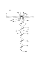
図1は、本発明の一実施形態に係る地中構造物10の構成を示す正面図である。図2は、本発明の一実施形態に係るペグ12の構成を示す斜視図である。図1に示すように、地中構造物10およびペグ12は、固定対象物14を地表面Gにおいて固定するためのものであり、地中構造物10の主要部はペグ12で構成されている。図1に示す固定対象物14はエア遊具であり、ペグ12は、エア遊具の固定綱14aを固定できるように構成されている。なお、固定対象物14は、エア遊具に限定されるものではなく、テント用張り綱、ペット用引き綱およびサッカーゴール等であってもよい。
FIG. 1 is a front view showing a configuration of an
図1に示すように、地中構造物10は、地中に埋め込まれた棒状の軸部16と、軸部16に螺旋状に設けられた掘削羽根18と、軸部16を周方向に回転させるための回転力が入力される入力部20と、結合基部22と、固定対象物14に結合される結合部24とを備えている。図2に示すように、軸部16、掘削羽根18、入力部20および結合基部22は、独立した1つの部品であるペグ本体26を構成するように一体的に形成されている。結合部24は、ペグ本体26の結合基部22に対して着脱自在に装着されている。なお、ペグ本体26および結合部24の材質は、特に限定されるものではないが、本実施形態では、アルミニウムまたは鉄等の金属が用いられている。また、ペグ本体26の成形方法は、鋳造加工や鍛造加工など特に限定されるものではないが、本実施形態では、母材から削り出す切削加工が用いられている。
As shown in FIG. 1, the
図1に示すように、軸部16は、地表面Gよりも下方の地中に完全に埋め込まれる棒状の部材である。軸部16の断面形状は円形であり、軸部16の下端部16aは、下方に向かうにつれて直径が小さくなるように尖って形成されている。
As shown in FIG. 1, the
図2に示すように、軸部16の上部には、円柱状の頭部28と六角柱状の入力部20とが軸方向に連続して設けられている。本実施形態の入力部20は、軸部16の軸方向からインパクトレンチ等の工具が装着される工具装着部20aを有している。つまり、入力部20の6つの側面は、軸部16の軸に対して平行に配置されており、各側面が、軸部16の軸方向から工具が装着される工具装着部20aとなっている。
As shown in FIG. 2, a
図2に示すように、頭部28および入力部20の中央部には、ねじ孔30が形成されており、ねじ孔30の開口が入力部20の上端面20bに開かれている。本実施形態では、ねじ孔30が形成された頭部28および入力部20の全体が、結合部24が着脱自在に装着される結合基部22となっている。
As shown in FIG. 2, a
図1に示すように、掘削羽根18は、第1部分18a、第2部分18bおよび第3部分18cに区分けされており、これらの直径は、下方から上方に向けて段階的に拡大するようにD1、D2およびD3(D1<D2<D3)とされている。第1部分18a、第2部分18bおよび第3部分18cの巻き数は、いずれも1周以上とされている。また、第1部分18aと第2部分18bとの境界部および第2部分18bと第3部分18cとの境界部には、掘削羽根18の直径が急拡大するように段差部32a,32bが形成されている。
As shown in FIG. 1, the
図2に示すように、結合部24は、本体部34と、第1ナット36と、回動部材38と、第2ナット40とを有している。本体部34は、回動部材38を支持するための円柱状の支持部42と、支持部42の下端部に設けられた雄ねじ部44と、支持部42の上端部に設けられた入力部46とを有している。雄ねじ部44の外径は、支持部42の外径よりも小さくされている。支持部42の外周面には、雄ねじ42aが形成されており、雄ねじ部44の外周面には、雄ねじ44aが形成されている。入力部46は、手動のレンチや電動のインパクトレンチ等の工具から回転力が入力される部分であり、本実施形態では六角柱状に形成されている。
As shown in FIG. 2, the
図2に示すように、第1ナット36および第2ナット40は、本体部34の外周において、回動部材38を上下方向から挟んで固定するものである。第1ナット36には、支持部42の雄ねじ42aに螺合される雌ねじ36aが形成されており、第2ナット40には、支持部42の雄ねじ42aに螺合される雌ねじ40aが形成されている。
As shown in FIG. 2, the
図2に示すように、回動部材38は、本体部34の支持部42に対して回動可能に取り付けられるものであり、支持部42が挿通される貫通孔48aを構成する第1環状部48と、固定対象物14(図1)が挿通される貫通孔50aを構成する第2環状部50と、第1環状部48と第2環状部50とを連結する連結部52とを有している。第1環状部48は、その断面が四角形になるように形成されており、第2環状部50は、その断面が円形になるように形成されている。
As shown in FIG. 2, the
図1に示すように、ペグ12を用いて固定対象物14を固定する際には、ペグ本体26を地中に埋め込む第1工程と、ペグ本体26に結合部24を取り付ける第2工程と、結合部24を固定対象物14に結合する第3工程とをこの順に実行する。
As shown in FIG. 1, when fixing the fixed
第1工程では、まず、図1に示す固定対象物14について固定すべき部分を確認し、その部分の近傍においてペグ本体26の埋め込み位置Pを決定する。続いて、ペグ本体26における軸部16の下端部16aを埋め込み位置Pに配置し、ペグ本体26における入力部20の上端面20b(図2)をハンマー等で叩いて、軸部16の下端部16aを地中に埋め込む。
In the first step, first, a portion to be fixed on the fixed
その後、入力部20の工具装着部20aにインパクトレンチ等の工具を装着し、当該工具から入力部20に周方向(正方向)の回転力を入力する。すると、ペグ本体26の全体が正方向に回転され、掘削羽根18の推進作用でペグ本体26が地中深くに埋め込まれる。入力部20および結合基部22の全体が、掘削羽根18で形成された有底孔54に到達すると、工具装着部20aから工具を取り外す。第1工程が終了した段階において、入力部20および結合基部22の全体は、掘削羽根18で形成された有底孔54に配置されており、ペグ本体26の上部は、地表面Gから上方に突出していない。
Thereafter, a tool such as an impact wrench is mounted on the
第2工程では、図2に示すように、結合部24の雄ねじ44aを、ペグ本体26のねじ孔30に螺合し、結合部24の本体部34をペグ本体26の結合基部22に接続する。このとき、ペグ本体26の入力部46にインパクトレンチ等の工具を装着し、当該工具から入力部46に周方向の回転力を入力する。結合基部22に対する本体部34の接続が完了すると、第1ナット36、回動部材38および第2ナット40を、本体部34の外周に配置し、回動部材38を第1ナット36および第2ナット40で上下方向から挟んで固定する。
In the second step, as shown in FIG. 2, the
第3工程では、図1に示す固定対象物14の固定綱14aを第2環状部50の貫通孔50aに挿通させて、第2環状部50を固定綱14aに結合する。なお、固定対象物14に対する結合部24の結合方法は、本実施形態に限定されるものではなく、例えば、第2環状部50を固定対象部14に設けられたフック部(図示省略)に引っ掛ける方法が用いられてもよい。
In the third step, the fixed
図3は、地中構造物10における固定対象物14を固定しない状態を示す正面図である。図3に示すように、地中構造物10を用いて固定対象物14(図1)を固定しないときには、結合部24(図1)に代えて、有底孔54を塞ぐ蓋体60を結合基部22に装着する。蓋体60は、地表面Gにおいて有底孔54の開口を塞ぐ板状の蓋板部62と、蓋板部62を支持する支持部64とを有している。本実施形態の蓋板部62および支持部64は、アルミニウムまたはアルミニウム合金で一体的に形成されている。
FIG. 3 is a front view showing a state where the fixed
図4は蓋体60の構成を示す図であり、(A)は平面図、(B)は正面図である。図4(A)に示すように、蓋体60の蓋板部62は、平面視で円形の板状に形成されており、蓋板部62の上面中央部には、六角レンチが挿入される平面視で六角形の有底孔62aが形成されている。図4(B)に示すように、蓋板部62の厚さは、中央部が最も厚くなっており、中央部から外周部に向かうにつれて徐々に薄くなっている。また、蓋板部62の下面中央部には、円柱状の支持部64が設けられており、支持部64の外周面には、結合基部22のねじ孔30(図3)に螺合される雄ねじ64aが形成されている。
4A and 4B are diagrams showing the configuration of the
図3に示すように、蓋体60をペグ本体26の結合基部22に結合する際には、まず、支持部64の雄ねじ64aを結合基部22のねじ孔30に対して位置決めする。続いて、六角レンチ(図示省略)を有底孔62a(図4(A))に挿入し、これを用いて蓋体60の全体を周方向に回転させる。すると、支持部64の雄ねじ64aが結合基部22のねじ孔30に螺合され、蓋板部62が地表面Gにおいて支持される。地表面Gが傾斜している場合やペグ本体26が地表面Gに対して傾斜した状態で挿入された場合には、蓋板部62と地表面Gとの間に隙間が生じることがある。この場合には、当該隙間を無くすために、アルミニウムまたはアルミニウム合金で形成された蓋板部62を地表面Gに沿うように変形させる。
As shown in FIG. 3, when the
この場合、ペグ本体26または少なくも結合基部22を蓋体60よりも硬質な材料で構成することにより、蓋体60に力を加えた際にペグ本体26または結合基部22を塑性変形させることなく蓋体60を塑性変形または弾性変形させることができる。例えば、地中構造物10は、ペグ本体26を鉄材(例えば、炭素鋼)で構成するとともに、蓋体26をアルミニウム材で構成することができる。これによれば、地中構造物10は、蓋板部62と地表面Gとの間に隙間が生じている場合において、蓋板部62上に自動車などが載ったり工具などによる衝撃が加わったりした場合には、蓋体60が積極的に変形して地表面Gと馴染むとともにペグ本体26の変形や損傷を防止することができる。
In this case, the
本実施形態によれば、上記構成により以下の各効果を奏することができる。すなわち、図1に示す固定対象物14に結合される結合部24は、結合基部22に対して着脱自在に装着されているので、軸部16を回転させるための工具を入力部20に装着するときには、工具の装着や回転操作の障害となるおそれのある結合部24を結合基部22から離脱させることができる。これにより、軸部16を地中に埋め込んだり、地中から抜いたりするときの作業性を向上できる。
According to the present embodiment, the following effects can be achieved by the above configuration. That is, since the
図2に示す入力部20は、工具が軸部16の軸方向から装着される工具装着部20aを有しているので、入力部20が軸部16の上部に設けられていることと相まって、工具を容易に装着できる。
Since the
図1に示すように、入力部20および結合基部22の全体が掘削羽根18で形成された有底孔54に配置されているので、入力部20および結合基部22の一部が地表面Gから上方に突出することがない。したがって、結合部24を結合基部22から離脱させた状態では、地表面Gから上方に突出する部分を完全に無くすことができ、つまずきによる事故などを防止できる。
As shown in FIG. 1, the
図3に示すように、地中構造物10を用いて固定対象物14(図1)を固定しないときには、有底孔54を塞ぐ蓋体60が結合基部22に装着されるので、有底孔54に土やゴミが入ったり、有底孔54の開口部が崩れたりすることを防止できる。
As shown in FIG. 3, when the fixed object 14 (FIG. 1) is not fixed using the
図3に示す蓋板部62は、アルミニウムまたはアルミニウム合金などペグ本体26より変形し易い材料で形成されているので、蓋板部62を地表面Gに接するように変形させることができ、有底孔54に土やゴミが入ったり、有底孔54の開口部が崩れたりすることをより効果的に防止できる。
3 is formed of a material that is more easily deformed than the
なお、本発明の実施にあたっては、上記実施形態に限定されず、本発明の目的を逸脱しない限りにおいて種々の変更が可能である。例えば、上記実施形態では、図3に示す蓋板部62をアルミニウムまたはアルミニウム合金で形成しているが、この蓋板部62の表面には、アルマイト処理により酸化膜を形成してもよいし、この酸化膜を着色してもよい。蓋板部62を着色アルマイト処理すると、蓋板部62を目立たせることができるので、蓋板部62を指標として用いることができる。
In carrying out the present invention, the present invention is not limited to the above embodiment, and various modifications can be made without departing from the object of the present invention. For example, in the above embodiment, the
図5は、他の結合部70の構成および使用状態を示す正面図である。図1に示すように、上記実施形態では、結合部24が第2環状部50を有しているが、図5に示すように、結合部70は、固定対象物84に引っ掛けられるフック部72を有していてもよい。
FIG. 5 is a front view showing the configuration and use state of another
図5に示す結合部70は、本体部74と、第1ナット76と、回動部材78と、第2ナット80とを有している。回動部材78は、本体部74の外周に配置される環状部82と環状部82に接続されたフック部72とを有している。フック部72は、固定対象物84を上方から押さえることができるように、上方に向けて凸となる湾曲部72aを有している。なお、本発明の説明で用いる「結合」の語は、広い意味を有しており、固定対象物84をフック部72で上方から押さえることも「結合」の一態様である。
The
図6は、他の結合部86の構成を示す正面図である。図1に示すように、上記実施形態では、結合部24が互いに独立した複数の部品で構成されているが、図6に示すように、結合部86は独立した1つの部品として構成されてもよい。図6に示す結合部86は、固定対象物(図示省略)が挿通される貫通孔88aを構成する環状部88と、雄ねじ部90と、環状部88と雄ねじ部90とを連結する円柱状の連結部92とを有した所謂アイボルトで構成されている。雄ねじ部90の外周面には、雄ねじ90aが形成されている。図2に示すペグ本体26に結合部86を取り付ける際には、結合部86の雄ねじ90aをペグ本体26のねじ孔30に螺合させる。
FIG. 6 is a front view showing the configuration of another
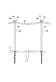
図7は、他の結合部94の構成および使用状態を示す正面図である。図7に結合部94は、工事現場等において、人や車両の進入を阻止するロープ96を支持するためのものであり、図6に示す結合部86と同様に、環状部98、雄ねじ部(図示省略)および円柱状の連結部100を有している。連結部100の長さは、ロープ96を張る高さに応じて定められており、本実施形態では、60〜90cmの範囲内で定められている。結合部94を備えるペグ102を用いてロープ96を支持する際には、複数のペグ102がロープ96に沿って配置され、各ペグ102の貫通孔98aにロープ96が挿通される。
FIG. 7 is a front view showing the configuration and use state of another
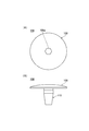
図8は他の蓋体106の構成を示す図であり、(A)は平面図、(B)は正面図である。図1に示す地中構造物10を用いて固定対象物14を固定しないときには、図3に示す蓋体60に代えて、図8(A),(B)に示す蓋体106を用いるようにしてもよい。図8(A)に示すように、蓋体106の蓋板部108は、平面視で円形の板状に形成されており、蓋板部108の上面中央部には、六角レンチが挿入される有底孔106aが形成されている。図8(B)に示すように、蓋板部108の下面中央部には、円柱状の支持部110が設けられている。支持部110は、下端部から上方に向かうにつれて外径が徐々に大きくなるように形成されており、支持部110の最大外径は、図3に示すねじ孔30の内径よりも大きくされている。したがって、支持部110をねじ孔30(図3)に挿入すると、支持部110がねじ孔30の内周面に当接されて固定される。
FIGS. 8A and 8B are diagrams showing the configuration of another
図9は、他の実施形態に係るペグ112の構成を示す斜視図である。図9に示すペグ112では、軸部114の上部に円柱状の雄ねじ部116が設けられている。雄ねじ部116の中央部には、平面視で六角形の有底孔118が形成されており、雄ねじ部116の外周面には、雄ねじ116aが形成されている。ペグ112においては、雄ねじ部116のうち有底孔118が形成された部分が、回転力が入力される「入力部」となっており、有底孔118の各側面は、軸部114の軸方向から工具が装着される工具装着部118aとなっている。また、雄ねじ部116のうち雄ねじ116aが形成された部分が、結合部(図示省略)が着脱自在に装着される「結合基部」となっている。図示していないが、ペグ112において用いられる結合部には、雄ねじ116aに螺合される雌ねじが形成されている。
FIG. 9 is a perspective view showing a configuration of a
図10は、他の実施形態に係るペグ122の構成を示す斜視図である。図10に示すペグ122では、軸部124の上部に円柱状の結合基部126が一体的に形成されている。結合基部126は、図2に示す結合部24の本体部34に相当する部分であり、結合基部126の外周面には、雄ねじ126aが形成されている。結合基部126の上部には、軸部124を回転させるための回転力が入力される六角柱状の入力部128が形成されている。
FIG. 10 is a perspective view showing a configuration of a
図10に示すペグ122を用いて固定対象物(図示省略)を固定する際には、まず、軸部124、結合基部126および入力部128を含むペグ本体130を、工具を用いて地中に埋め込む。続いて、結合部132を構成する第1ナット36、回動部材38および第2ナット40を結合基部126に取り付ける。このペグ122によれば、結合部132の部品数を減らすことができるので、施工性を向上できる。
When a fixed object (not shown) is fixed using the
G…地表面、10…地中構造物、12…ペグ、14…固定対象物、16…軸部、
18…掘削羽根、20…入力部、22…結合基部、24…結合部
G: Ground surface, 10 ... Underground structure, 12 ... Peg, 14 ... Fixed object, 16 ... Shaft part,
18 ... Excavation blade, 20 ... Input part, 22 ... Coupling base, 24 ... Coupling part
Claims (7)
地中に埋め込まれる棒状の軸部と、
前記軸部に螺旋状に設けられた掘削羽根と、
前記軸部の上部に設けられ、前記軸部を周方向に回転させるための回転力が入力される入力部と、
前記固定対象物に結合される結合部と、
前記軸部の上部に設けられ、前記結合部が着脱自在に装着される結合基部とを備え、
前記結合部は、
雄ねじが形成された円柱状の支持部の下端部に同支持部よりも小径に形成されて前記結合基部に着脱自在に螺合して装着される雄ネジ部を有した本体部と、
前記本体部における前記支持部が貫通する第1環状部を有して同支持部に対して回動可能に取り付けられて前記固定対象物が結合される回動部材と、
前記本体部における前記支持部に対して前記回動部材の両側から螺合して同回動部材を挟んで固定する第1ナットおよび第2ナットとを備える、ペグ。
A peg for fixing a fixed object on the ground surface,
A rod-shaped shaft part embedded in the ground,
Excavation blades spirally provided on the shaft portion;
An input portion provided at an upper portion of the shaft portion, to which a rotational force for rotating the shaft portion in a circumferential direction is input;
A coupling portion coupled to the fixed object;
A coupling base provided on an upper portion of the shaft portion, to which the coupling portion is detachably mounted;
The coupling portion is
A main body portion having a male screw portion that is formed in a lower diameter portion of the columnar support portion on which the male screw is formed, smaller in diameter than the support portion, and is detachably screwed to and attached to the coupling base portion;
A rotating member that has a first annular portion through which the support portion in the main body portion passes and is rotatably attached to the support portion and to which the fixed object is coupled;
A peg comprising a first nut and a second nut that are screwed into both sides of the rotating member and fixed to the support portion of the main body portion with the rotating member interposed therebetween.
地中に埋め込まれた棒状の軸部と、
前記軸部に螺旋状に設けられた掘削羽根と、
前記軸部の上部に設けられ、前記軸部を周方向に回転させるための回転力が入力される入力部と、
前記固定対象物に結合される結合部と、
前記軸部の上部に設けられ、前記結合部が着脱自在に装着される結合基部とを備え、
前記結合部は、
雄ねじが形成された円柱状の支持部の下端部に同支持部よりも小径に形成されて前記結合基部に着脱自在に螺合して装着される雄ネジ部を有した本体部と、
前記本体部における前記支持部が貫通する第1環状部を有して同支持部に対して回動可能に取り付けられて前記固定対象物が結合される回動部材と、
前記本体部における前記支持部に対して前記回動部材の両側から螺合して同回動部材を挟んで固定する第1ナットおよび第2ナットとを備え、
前記軸部および前記掘削羽根は、前記入力部から入力される回転力で周方向に回転されることによって、前記掘削羽根の推進作用で前記地中に埋め込まれており、
前記入力部および前記結合基部の全体は、前記掘削羽根で形成された有底孔に配置されている、地中構造物。
An underground structure for fixing a fixed object on the ground surface,
A rod-shaped shaft embedded in the ground,
Excavation blades spirally provided on the shaft portion;
An input portion provided at an upper portion of the shaft portion, to which a rotational force for rotating the shaft portion in a circumferential direction is input;
A coupling portion coupled to the fixed object;
A coupling base provided on an upper portion of the shaft portion, to which the coupling portion is detachably mounted;
The coupling portion is
A main body portion having a male screw portion that is formed in a lower diameter portion of the columnar support portion on which the male screw is formed, smaller in diameter than the support portion, and is detachably screwed to and attached to the coupling base portion;
A rotating member that has a first annular portion through which the support portion in the main body portion passes and is rotatably attached to the support portion and to which the fixed object is coupled;
A first nut and a second nut that are screwed from both sides of the rotation member to the support portion in the main body portion and fixed with the rotation member interposed therebetween;
The shaft portion and the excavation blade are embedded in the ground by the propelling action of the excavation blade by being rotated in the circumferential direction by the rotational force input from the input portion,
The whole of the input part and the coupling base part is an underground structure arranged in a bottomed hole formed by the excavation blade.
前記固定対象物を固定しないときには、前記有底孔を塞ぐ蓋体が前記結合部に代えて前記結合基部に装着される、請求項5に記載の地中構造物。 When fixing the fixed object, the coupling portion is attached to the coupling base,
The underground structure according to claim 5, wherein a lid that closes the bottomed hole is attached to the coupling base instead of the coupling when the fixed object is not fixed.
The ground according to claim 6, wherein the lid has a plate-like lid plate portion that closes the opening of the bottomed hole on the ground surface and is made of a material that is more easily deformed than the coupling base portion. Structure.
Priority Applications (1)
| Application Number | Priority Date | Filing Date | Title |
|---|---|---|---|
| JP2016138226A JP6431007B2 (en) | 2016-07-13 | 2016-07-13 | Pegs and underground structures |
Applications Claiming Priority (1)
| Application Number | Priority Date | Filing Date | Title |
|---|---|---|---|
| JP2016138226A JP6431007B2 (en) | 2016-07-13 | 2016-07-13 | Pegs and underground structures |
Publications (2)
| Publication Number | Publication Date |
|---|---|
| JP2018009344A JP2018009344A (en) | 2018-01-18 |
| JP6431007B2 true JP6431007B2 (en) | 2018-11-28 |
Family
ID=60995130
Family Applications (1)
| Application Number | Title | Priority Date | Filing Date |
|---|---|---|---|
| JP2016138226A Active JP6431007B2 (en) | 2016-07-13 | 2016-07-13 | Pegs and underground structures |
Country Status (1)
| Country | Link |
|---|---|
| JP (1) | JP6431007B2 (en) |
Families Citing this family (1)
| Publication number | Priority date | Publication date | Assignee | Title |
|---|---|---|---|---|
| JP2022128847A (en) * | 2021-02-24 | 2022-09-05 | 有限会社太悦鉄工 | Peg |
Family Cites Families (11)
| Publication number | Priority date | Publication date | Assignee | Title |
|---|---|---|---|---|
| JPS4992607U (en) * | 1972-11-27 | 1974-08-10 | ||
| JPS57133647U (en) * | 1980-11-15 | 1982-08-20 | ||
| JPS5812327U (en) * | 1981-07-15 | 1983-01-26 | ナショナル住宅産業株式会社 | stake |
| JPH077375Y2 (en) * | 1989-04-05 | 1995-02-22 | 株式会社吾妻商会 | Road division marking tool |
| JP2579790Y2 (en) * | 1992-07-23 | 1998-08-27 | 岡部株式会社 | Anchor reinforcement holding device |
| JP2006312878A (en) * | 2006-08-28 | 2006-11-16 | Asahi Tec Corp | Underground anchor |
| JP2010236344A (en) * | 2009-03-30 | 2010-10-21 | Kurinaa Korea Co Ltd | Center axis correction device for facility strut fixing device |
| JP5783819B2 (en) * | 2011-06-23 | 2015-09-24 | 株式会社大林組 | Natural mountain reinforcement |
| US8997278B1 (en) * | 2013-05-08 | 2015-04-07 | Rick Vanvliet | Beach towel anchor system |
| US20160032612A1 (en) * | 2014-08-01 | 2016-02-04 | Chia-Ling Huang | Tent peg structure with illumination device |
| JP6551964B2 (en) * | 2014-09-18 | 2019-07-31 | 有限会社太悦鉄工 | Peg |
-
2016
- 2016-07-13 JP JP2016138226A patent/JP6431007B2/en active Active
Also Published As
| Publication number | Publication date |
|---|---|
| JP2018009344A (en) | 2018-01-18 |
Similar Documents
| Publication | Publication Date | Title |
|---|---|---|
| EP2701870A1 (en) | Bolt on drive assembly for a core drill with high strength spoked reinforcer with adapter | |
| US20060033003A1 (en) | Pocket former | |
| JP2010216128A (en) | Pile locking device and pile locking method | |
| JP3135921U (en) | Anchor pile for horizontal strength | |
| US9574365B2 (en) | Clamps for repairing posts and methods and/or arrangements for repairing such posts with said clamps | |
| JP6551964B2 (en) | Peg | |
| JP2018009344A (en) | Peg and underground structure | |
| US8464738B2 (en) | Stake system and method for soft material | |
| JP4375566B2 (en) | High strength anchor | |
| JP2013079516A (en) | Frame base | |
| JP2010138687A (en) | Construction jig for steel pipe pile, and construction method for the steel pipe pile | |
| JP7412816B1 (en) | Tip part of ground-mounted anchor type fixture | |
| KR102039997B1 (en) | Supporting piller for pepper | |
| JP6246576B2 (en) | Connecting bolt, tool and construction method | |
| KR102672328B1 (en) | Auxiliary steel pipe connecting device detachable from PHC pile and construction method using it | |
| KR101171285B1 (en) | Attachable joint apparatus of the different sized pile for foundation work | |
| JP2014084603A (en) | Pile and pile unit | |
| JP5623665B1 (en) | Cap for driving steel pipe pile driving device and driving method using the same | |
| KR102204014B1 (en) | the separator structure of combine track roller | |
| JP3215144U (en) | Split pillar building column equipment | |
| KR101956561B1 (en) | Supportting piller for pepper | |
| JP2009256881A (en) | Construction method of net for preventing fall of exfoliation concrete | |
| JP2016003549A (en) | Rotary burial-type support and method for rotatively burying support | |
| US20190093301A1 (en) | Animal trap disposable anchor driver | |
| JP2006104772A (en) | Drilling device |
Legal Events
| Date | Code | Title | Description |
|---|---|---|---|
| A977 | Report on retrieval |
Free format text: JAPANESE INTERMEDIATE CODE: A971007 Effective date: 20180518 |
|
| A131 | Notification of reasons for refusal |
Free format text: JAPANESE INTERMEDIATE CODE: A131 Effective date: 20180522 |
|
| A521 | Written amendment |
Free format text: JAPANESE INTERMEDIATE CODE: A523 Effective date: 20180719 |
|
| A131 | Notification of reasons for refusal |
Free format text: JAPANESE INTERMEDIATE CODE: A131 Effective date: 20180801 |
|
| A521 | Written amendment |
Free format text: JAPANESE INTERMEDIATE CODE: A523 Effective date: 20180919 |
|
| TRDD | Decision of grant or rejection written | ||
| A01 | Written decision to grant a patent or to grant a registration (utility model) |
Free format text: JAPANESE INTERMEDIATE CODE: A01 Effective date: 20181009 |
|
| A61 | First payment of annual fees (during grant procedure) |
Free format text: JAPANESE INTERMEDIATE CODE: A61 Effective date: 20181101 |
|
| R150 | Certificate of patent or registration of utility model |
Ref document number: 6431007 Country of ref document: JP Free format text: JAPANESE INTERMEDIATE CODE: R150 |