JP6430248B2 - Packet transmitting / receiving apparatus and method in broadcasting and communication system - Google Patents
Packet transmitting / receiving apparatus and method in broadcasting and communication system Download PDFInfo
- Publication number
- JP6430248B2 JP6430248B2 JP2014515715A JP2014515715A JP6430248B2 JP 6430248 B2 JP6430248 B2 JP 6430248B2 JP 2014515715 A JP2014515715 A JP 2014515715A JP 2014515715 A JP2014515715 A JP 2014515715A JP 6430248 B2 JP6430248 B2 JP 6430248B2
- Authority
- JP
- Japan
- Prior art keywords
- fec
- information
- packet
- block
- code
- Prior art date
- Legal status (The legal status is an assumption and is not a legal conclusion. Google has not performed a legal analysis and makes no representation as to the accuracy of the status listed.)
- Active
Links
- 238000000034 method Methods 0.000 title claims description 54
- 238000004891 communication Methods 0.000 title description 6
- 230000008439 repair process Effects 0.000 claims description 30
- 238000010586 diagram Methods 0.000 description 49
- 230000005540 biological transmission Effects 0.000 description 45
- 230000011664 signaling Effects 0.000 description 39
- 238000004904 shortening Methods 0.000 description 24
- 238000004088 simulation Methods 0.000 description 12
- 238000012937 correction Methods 0.000 description 9
- 238000013507 mapping Methods 0.000 description 9
- 230000008569 process Effects 0.000 description 9
- 239000011159 matrix material Substances 0.000 description 8
- 230000015556 catabolic process Effects 0.000 description 4
- 238000006731 degradation reaction Methods 0.000 description 4
- 238000005538 encapsulation Methods 0.000 description 4
- 230000008901 benefit Effects 0.000 description 3
- 230000008602 contraction Effects 0.000 description 3
- 238000005315 distribution function Methods 0.000 description 3
- 230000003252 repetitive effect Effects 0.000 description 3
- 238000012986 modification Methods 0.000 description 2
- 230000004048 modification Effects 0.000 description 2
- 230000000694 effects Effects 0.000 description 1
- 238000002474 experimental method Methods 0.000 description 1
- 239000000284 extract Substances 0.000 description 1
- 230000000737 periodic effect Effects 0.000 description 1
- 238000004092 self-diagnosis Methods 0.000 description 1
- 230000009897 systematic effect Effects 0.000 description 1
Images


Classifications
-
- H—ELECTRICITY
- H03—ELECTRONIC CIRCUITRY
- H03M—CODING; DECODING; CODE CONVERSION IN GENERAL
- H03M13/00—Coding, decoding or code conversion, for error detection or error correction; Coding theory basic assumptions; Coding bounds; Error probability evaluation methods; Channel models; Simulation or testing of codes
- H03M13/29—Coding, decoding or code conversion, for error detection or error correction; Coding theory basic assumptions; Coding bounds; Error probability evaluation methods; Channel models; Simulation or testing of codes combining two or more codes or code structures, e.g. product codes, generalised product codes, concatenated codes, inner and outer codes
- H03M13/2906—Coding, decoding or code conversion, for error detection or error correction; Coding theory basic assumptions; Coding bounds; Error probability evaluation methods; Channel models; Simulation or testing of codes combining two or more codes or code structures, e.g. product codes, generalised product codes, concatenated codes, inner and outer codes using block codes
-
- H—ELECTRICITY
- H04—ELECTRIC COMMUNICATION TECHNIQUE
- H04L—TRANSMISSION OF DIGITAL INFORMATION, e.g. TELEGRAPHIC COMMUNICATION
- H04L1/00—Arrangements for detecting or preventing errors in the information received
- H04L1/004—Arrangements for detecting or preventing errors in the information received by using forward error control
- H04L1/0056—Systems characterized by the type of code used
- H04L1/0057—Block codes
-
- H—ELECTRICITY
- H03—ELECTRONIC CIRCUITRY
- H03M—CODING; DECODING; CODE CONVERSION IN GENERAL
- H03M13/00—Coding, decoding or code conversion, for error detection or error correction; Coding theory basic assumptions; Coding bounds; Error probability evaluation methods; Channel models; Simulation or testing of codes
- H03M13/03—Error detection or forward error correction by redundancy in data representation, i.e. code words containing more digits than the source words
- H03M13/05—Error detection or forward error correction by redundancy in data representation, i.e. code words containing more digits than the source words using block codes, i.e. a predetermined number of check bits joined to a predetermined number of information bits
- H03M13/09—Error detection only, e.g. using cyclic redundancy check [CRC] codes or single parity bit
-
- H—ELECTRICITY
- H03—ELECTRONIC CIRCUITRY
- H03M—CODING; DECODING; CODE CONVERSION IN GENERAL
- H03M13/00—Coding, decoding or code conversion, for error detection or error correction; Coding theory basic assumptions; Coding bounds; Error probability evaluation methods; Channel models; Simulation or testing of codes
- H03M13/37—Decoding methods or techniques, not specific to the particular type of coding provided for in groups H03M13/03 - H03M13/35
- H03M13/373—Decoding methods or techniques, not specific to the particular type of coding provided for in groups H03M13/03 - H03M13/35 with erasure correction and erasure determination, e.g. for packet loss recovery or setting of erasures for the decoding of Reed-Solomon codes
-
- H—ELECTRICITY
- H03—ELECTRONIC CIRCUITRY
- H03M—CODING; DECODING; CODE CONVERSION IN GENERAL
- H03M13/00—Coding, decoding or code conversion, for error detection or error correction; Coding theory basic assumptions; Coding bounds; Error probability evaluation methods; Channel models; Simulation or testing of codes
- H03M13/65—Purpose and implementation aspects
- H03M13/6522—Intended application, e.g. transmission or communication standard
- H03M13/6547—TCP, UDP, IP and associated protocols, e.g. RTP
-
- H—ELECTRICITY
- H04—ELECTRIC COMMUNICATION TECHNIQUE
- H04L—TRANSMISSION OF DIGITAL INFORMATION, e.g. TELEGRAPHIC COMMUNICATION
- H04L1/00—Arrangements for detecting or preventing errors in the information received
- H04L1/0001—Systems modifying transmission characteristics according to link quality, e.g. power backoff
- H04L1/0023—Systems modifying transmission characteristics according to link quality, e.g. power backoff characterised by the signalling
-
- H—ELECTRICITY
- H04—ELECTRIC COMMUNICATION TECHNIQUE
- H04L—TRANSMISSION OF DIGITAL INFORMATION, e.g. TELEGRAPHIC COMMUNICATION
- H04L1/00—Arrangements for detecting or preventing errors in the information received
- H04L1/004—Arrangements for detecting or preventing errors in the information received by using forward error control
- H04L1/0041—Arrangements at the transmitter end
-
- H—ELECTRICITY
- H04—ELECTRIC COMMUNICATION TECHNIQUE
- H04L—TRANSMISSION OF DIGITAL INFORMATION, e.g. TELEGRAPHIC COMMUNICATION
- H04L1/00—Arrangements for detecting or preventing errors in the information received
- H04L1/004—Arrangements for detecting or preventing errors in the information received by using forward error control
- H04L1/0045—Arrangements at the receiver end
- H04L1/0047—Decoding adapted to other signal detection operation
-
- H—ELECTRICITY
- H04—ELECTRIC COMMUNICATION TECHNIQUE
- H04L—TRANSMISSION OF DIGITAL INFORMATION, e.g. TELEGRAPHIC COMMUNICATION
- H04L1/00—Arrangements for detecting or preventing errors in the information received
- H04L1/004—Arrangements for detecting or preventing errors in the information received by using forward error control
- H04L1/0056—Systems characterized by the type of code used
- H04L1/0061—Error detection codes
-
- H—ELECTRICITY
- H03—ELECTRONIC CIRCUITRY
- H03M—CODING; DECODING; CODE CONVERSION IN GENERAL
- H03M13/00—Coding, decoding or code conversion, for error detection or error correction; Coding theory basic assumptions; Coding bounds; Error probability evaluation methods; Channel models; Simulation or testing of codes
- H03M13/03—Error detection or forward error correction by redundancy in data representation, i.e. code words containing more digits than the source words
- H03M13/05—Error detection or forward error correction by redundancy in data representation, i.e. code words containing more digits than the source words using block codes, i.e. a predetermined number of check bits joined to a predetermined number of information bits
- H03M13/11—Error detection or forward error correction by redundancy in data representation, i.e. code words containing more digits than the source words using block codes, i.e. a predetermined number of check bits joined to a predetermined number of information bits using multiple parity bits
- H03M13/1102—Codes on graphs and decoding on graphs, e.g. low-density parity check [LDPC] codes
-
- H—ELECTRICITY
- H03—ELECTRONIC CIRCUITRY
- H03M—CODING; DECODING; CODE CONVERSION IN GENERAL
- H03M13/00—Coding, decoding or code conversion, for error detection or error correction; Coding theory basic assumptions; Coding bounds; Error probability evaluation methods; Channel models; Simulation or testing of codes
- H03M13/03—Error detection or forward error correction by redundancy in data representation, i.e. code words containing more digits than the source words
- H03M13/05—Error detection or forward error correction by redundancy in data representation, i.e. code words containing more digits than the source words using block codes, i.e. a predetermined number of check bits joined to a predetermined number of information bits
- H03M13/13—Linear codes
- H03M13/15—Cyclic codes, i.e. cyclic shifts of codewords produce other codewords, e.g. codes defined by a generator polynomial, Bose-Chaudhuri-Hocquenghem [BCH] codes
- H03M13/151—Cyclic codes, i.e. cyclic shifts of codewords produce other codewords, e.g. codes defined by a generator polynomial, Bose-Chaudhuri-Hocquenghem [BCH] codes using error location or error correction polynomials
- H03M13/1515—Reed-Solomon codes
-
- H—ELECTRICITY
- H03—ELECTRONIC CIRCUITRY
- H03M—CODING; DECODING; CODE CONVERSION IN GENERAL
- H03M13/00—Coding, decoding or code conversion, for error detection or error correction; Coding theory basic assumptions; Coding bounds; Error probability evaluation methods; Channel models; Simulation or testing of codes
- H03M13/37—Decoding methods or techniques, not specific to the particular type of coding provided for in groups H03M13/03 - H03M13/35
- H03M13/3761—Decoding methods or techniques, not specific to the particular type of coding provided for in groups H03M13/03 - H03M13/35 using code combining, i.e. using combining of codeword portions which may have been transmitted separately, e.g. Digital Fountain codes, Raptor codes or Luby Transform [LT] codes
Description
本発明は、放送及び通信システムに関し、特に、パケット送受信装置及び方法に関する。 The present invention relates to broadcasting and communication systems, and more particularly, to a packet transmitting / receiving apparatus and method.
様々なコンテンツの増加及び高解像度(High Definition:HD)コンテンツ及び超高解像度(Ultra High Definition:UHD)コンテンツのような高容量コンテンツの増加の結果として、ネットワークトラフィックと関連したデータ輻輳(data Congestion)は、さらに悪化している。結果的に、送信器(Sender)(例えば、ホストA)により送信されたコンテンツは、受信器(Receiver)(例えば、ホストB)に正常に配信されず、コンテンツの一部は、経路上で損失される状況が発生する場合がある。 Data Congestion associated with network traffic as a result of various content growth and increased high-capacity content such as High Definition (HD) content and Ultra High Definition (UHD) content Is getting worse. As a result, content transmitted by a sender (eg, host A) is not successfully delivered to a receiver (eg, host B), and some of the content is lost on the path Situations may occur.
一般的に、データは、パケット単位で送信される。このように、データ損失は、パケット単位で発生する場合がある。したがって、受信器は、ネットワーク上でデータの損失によりパケットを受信することができないので、損失されたパケット内のデータがわからない。したがって、オーディオの品質劣化、ビデオの画質劣化、画面クラック、字幕欠落、ファイル損失などのような様々な形態でユーザの不便さをもたらす。このような理由で、ネットワーク上で発生し得るデータ損失を復旧するための方法が要求される。 In general, data is transmitted in units of packets. Thus, data loss may occur on a packet basis. Therefore, the receiver cannot receive the packet due to data loss on the network, and therefore does not know the data in the lost packet. Therefore, it causes inconvenience to the user in various forms such as audio quality degradation, video image quality degradation, screen cracks, missing subtitles, and file loss. For this reason, a method for recovering data loss that may occur on the network is required.
したがって、コンピュータ又はユーザインターフェースで自己診断項目を選択する時に、装置の自己診断を快適に実行するためのシステム及び方法に対する必要性が存在する。 Accordingly, there is a need for a system and method for comfortably performing device self-diagnosis when selecting self-diagnostic items on a computer or user interface.
上記情報は、本発明の理解を助けるために背景情報だけが提示される。本発明についての先行技術として適用することができるか否かについては、何らの決定及び何らの主張もするものではない。 For the above information, only background information is presented to aid understanding of the present invention. No decision or claim is made as to whether it can be applied as prior art to the present invention.
本発明の目的は、少なくとも上述した問題点及び/又は不都合に取り組み、少なくとも以下の利便性を提供することにある。すなわち、本発明の目的は、ネットワーク上で発生するデータ損失を復旧する放送及び通信システムにおけるパケット送受信装置及び方法を提供することにある。 An object of the present invention is to address at least the above-mentioned problems and / or disadvantages and provide at least the following conveniences. That is, an object of the present invention is to provide a packet transmitting / receiving apparatus and method in a broadcasting and communication system that recovers data loss occurring on a network.
本発明の他の目的は、第1の順方向エラー訂正(Forward Error Correction:FEC)及び第2のFECのそれぞれの適用/不適用を表示する情報又は他の符号化構成(Encoding Configuration)関連情報をシグナリングする放送及び通信システムにおけるパケット送受信装置及び方法を提供することにある。 Another object of the present invention is to display information indicating the application / non-application of each of the first forward error correction (FEC) and the second FEC or other encoding configuration related information. It is an object to provide a packet transmitting / receiving apparatus and method in a broadcasting and communication system.
本発明のまた他の目的は、ネットワーク状況又はコンテンツのサービス品質(QoS)に基づいて選択的にFECを適用する放送及び通信システムにおけるパケット送受信装置及び方法を提供することにある。 It is another object of the present invention to provide a packet transmitting / receiving apparatus and method in a broadcasting and communication system that selectively apply FEC based on network conditions or quality of service (QoS) of content.
本発明のさらにまた他の目的は、サービスがすでに進行している間に新たな受信器がFEC関連情報を予め認識するようにする放送及び通信システムにおけるパケット送受信装置及び方法を提供することにある。 It is still another object of the present invention to provide a packet transmitting / receiving apparatus and method in a broadcasting and communication system that allows a new receiver to recognize FEC related information in advance while a service is already in progress. .
上記のような目的を達成するために、本発明の一態様によれば、インターネットプロトコルに基づいてマルチメディアサービスをサポートする放送システムにおけるパケット構成方法が提供される。上記方法は、入力されたソースブロックを少なくとも1つのサブブロックに分割するステップと、上記少なくとも1つのサブブロックの各々を同一の長さを有する情報ペイロードを含む情報ブロックに変換するステップと、上記少なくとも1つのサブブロックの各々の情報ブロックを符号化することにより第1のパリティブロックを生成するステップと、上記少なくとも1つのサブブロック全体を含むソースブロックに第2のパリティブロックを付加するステップとを有することを特徴とする。 In order to achieve the above object, according to an aspect of the present invention, there is provided a packet configuration method in a broadcasting system that supports multimedia services based on an Internet protocol. The method includes dividing an input source block into at least one sub-block, converting each of the at least one sub-block into an information block including an information payload having the same length, and Generating a first parity block by encoding each information block of one sub-block, and adding a second parity block to a source block including the entire at least one sub-block It is characterized by that.
本発明の他の態様によれば、インターネットプロトコルに基づいてマルチメディアサービスをサポートする放送システムにおけるパケット構成装置が提供される。上記装置は、入力されたソースブロックを少なくとも1つのサブブロックに分割し、上記少なくとも1つのサブブロックの各々を同一の長さを有する情報ペイロードを含む情報ブロックに変換するトランスポートプロトコルパケタイザと、上記少なくとも1つのサブブロックの各々の情報ブロックを符号化することにより第1のパリティブロックを生成する第1のエンコーダと、上記少なくとも1つのサブブロック全体を含むソースブロックに第2のパリティブロックを付加する第2のエンコーダとを有することを特徴とする。 According to another aspect of the present invention, there is provided a packet configuration apparatus in a broadcasting system that supports multimedia services based on an Internet protocol. The apparatus divides an input source block into at least one sub-block, and converts each of the at least one sub-block into an information block including an information payload having the same length; and a transport protocol packetizer. A first encoder that generates a first parity block by encoding each information block of the at least one sub-block, and a second parity block is added to the source block including the entire at least one sub-block. And a second encoder.
本発明のさらに他の態様によれば、インターネットプロトコルに基づいてマルチメディアサービスをサポートする放送システムにおけるパケット受信方法が提供される。上記方法は、送信器から送信された信号を復調するステップと、上記復調された信号から第2のパリティビットブロックを抽出するステップと、上記抽出された第2のパリティビットブロックに基づいてパケットを復号化するステップとを有し、上記第2のパリティビットブロックは、入力されたソースブロックを少なくとも1つのサブブロックに分割し、上記少なくとも1つのサブブロックの各々を同一の長さを有する情報ペイロードを含む情報ブロックに変換し、上記少なくとも1つのサブブロックの各々の情報ブロックを符号化することにより第1のパリティブロックを生成し、上記少なくとも1つのサブブロック全体を含むソースブロックに第2のパリティブロックを付加することにより生成されることを特徴とする。 According to still another aspect of the present invention, there is provided a packet receiving method in a broadcasting system that supports multimedia services based on an Internet protocol. The method includes demodulating a signal transmitted from a transmitter, extracting a second parity bit block from the demodulated signal, and extracting a packet based on the extracted second parity bit block. The second parity bit block divides the input source block into at least one sub-block and each of the at least one sub-block has the same length Is converted into an information block, and each information block of the at least one sub-block is encoded to generate a first parity block, and a second parity is generated in the source block including the entire at least one sub-block. It is generated by adding a block.
本発明のさらなる他の態様によれば、インターネットプロトコルに基づいてマルチメディアサービスをサポートする放送システムにおけるパケット受信装置が提供される。上記装置は、送信器から送信された信号を復調する復調部と、上記復調された信号から第2のパリティビットブロックを抽出する制御部と、上記抽出された第2のパリティビットブロックに基づいてパケットを復号化する復号部とを有し、上記第2のパリティビットブロックは、入力されたソースブロックを少なくとも1つのサブブロックに分割し、上記少なくとも1つのサブブロックの各々を同一の長さを有する情報ペイロードを含む情報ブロックに変換し、上記少なくとも1つのサブブロックの各々の情報ブロックを符号化することにより第1のパリティブロックを生成し、上記少なくとも1つのサブブロック全体を含むソースブロックに第2のパリティブロックを付加することにより生成されることを特徴とする。 According to still another aspect of the present invention, there is provided a packet receiving apparatus in a broadcasting system that supports multimedia services based on an Internet protocol. The apparatus is based on a demodulator that demodulates a signal transmitted from a transmitter, a controller that extracts a second parity bit block from the demodulated signal, and the extracted second parity bit block. The second parity bit block divides the input source block into at least one subblock, and each of the at least one subblock has the same length. A first parity block is generated by encoding each information block of the at least one sub-block, and a source block including the entire at least one sub-block is generated. It is generated by adding two parity blocks.
本発明によれば、第1のFEC及び第2のFECのそれぞれの適用/不適用を示す情報を含むFEC構成関連情報又は他の符号化構成関連情報をシグナリングし受信器に送信することにより、送信器は、選択的にFECが適用されたコンテンツを配信することができる。 According to the present invention, FEC configuration related information including information indicating application / non-application of each of the first FEC and the second FEC or other encoded configuration related information is signaled and transmitted to the receiver, The transmitter can selectively distribute content to which FEC is applied.
また、本発明によれば、ネットワーク状況又はコンテンツのサービス品質(QoS)に基づいて選択的にFECを適用することができる。 Further, according to the present invention, FEC can be selectively applied based on network conditions or content quality of service (QoS).
さらに、本発明によれば、第1のFEC及び第2のFECのそれぞれの適用/不適用を示す情報を含むFEC構成関連情報又は他の符号化構成関連情報を含むFEC制御情報を周期的に反復して送信するか、又は提案されたイン−バンドシグナリング方法でFEC構成関連情報を送信することにより、サービスがすでに進行中である状況で新たな受信器にもFEC構成関連情報を予め認識するようにすることができるので、新たな受信器もFEC復号化を実行することにより損失されたデータを復旧し、これにより、良質のサービスをユーザに提供することができる。 Furthermore, according to the present invention, FEC configuration related information including information indicating application / non-application of each of the first FEC and the second FEC or FEC control information including other coding configuration related information is periodically transmitted. By repeatedly transmitting or transmitting the FEC configuration related information with the proposed in-band signaling method, the FEC configuration related information is also recognized in advance by the new receiver in a situation where the service is already in progress. Therefore, the new receiver can also recover the lost data by performing the FEC decoding, thereby providing the user with a good quality service.
本発明の他の目的、利点、及び顕著な特徴は、添付の図面及び本発明の実施形態からなされた以下の詳細な説明から、この分野の当業者に明確になるはずである。 Other objects, advantages and salient features of the present invention will become apparent to those skilled in the art from the accompanying drawings and the following detailed description made from the embodiments of the present invention.
本発明の上述した及び他の様相、特徴、及び利点は、以下の添付図面が併用された後述の詳細な説明から、より一層明らかになるだろう。図面中、同一の図面参照符号は、同一の構成要素、特性、及び構造を意味することが分かるはずである。 The foregoing and other aspects, features, and advantages of the invention will become more apparent from the following detailed description, taken in conjunction with the accompanying drawings. In the drawings, it should be understood that the same reference numerals denote the same components, characteristics, and structures.
添付の図面を参照した下記の説明は、特許請求の範囲の記載及びこれと均等なものの範囲内で定められるような本発明の実施形態の包括的な理解を助けるために提供されるものであり、この理解を助けるために様々な特定の詳細を含むが、単なる1つの実施形態に過ぎない。従って、本発明の範囲及び趣旨を逸脱することなく、ここに説明する実施形態の様々な変更及び修正が可能であるということは、当該技術分野における通常の知識を有する者には明らかである。また、明瞭性と簡潔性の観点から、当業者に良く知られている機能や構成に関する具体的な説明は、省略する。 The following description with reference to the accompanying drawings is provided to assist in a comprehensive understanding of the embodiments of the present invention as defined in the appended claims and their equivalents. While including various specific details to aid in this understanding, it is merely one embodiment. Accordingly, it will be apparent to those skilled in the art that various changes and modifications can be made to the embodiments described herein without departing from the scope and spirit of the invention. In addition, from the viewpoints of clarity and conciseness, detailed descriptions of functions and configurations well known to those skilled in the art are omitted.
次の説明及び請求項に使用する用語及び単語は、辞典的意味に限定されるものではなく、発明者により本発明の理解を明確且つ一貫性があるようにするために使用する。従って、本発明の実施形態の説明が単に実例を提供するためのものであって、特許請求の範囲とこれと均等なものに基づいて定義される発明を限定する目的で提供するものでないことは、本発明の技術分野における通常の知識を持つ者には明らかである。 The terms and words used in the following description and claims are not limited to the dictionary meaning, but are used by the inventor to make the understanding of the present invention clear and consistent. Accordingly, the description of the embodiments of the present invention is merely provided for illustrative purposes and is not provided for the purpose of limiting the invention as defined by the claims and their equivalents. It will be apparent to those skilled in the art of the present invention.
英文明細書に記載の“a”、“an”、及び“the”、すなわち単数形は、コンテキスト中に特記で明示されない限り、複数形を含むことは、当業者には理解されることである。したがって、例えば、“コンポーネント表面(a component surface)”との記載は、1つ又は複数の表面を含む。 It will be understood by those skilled in the art that “a”, “an”, and “the”, ie, the singular forms in the English specification, include the plural unless the context clearly dictates otherwise. . Thus, for example, reference to “a component surface” includes one or more surfaces.
下記では、順方向エラー訂正(FEC)符号化方法について説明するが、このような方法によって、リードソロモン(RS)コード、低密度パリティ検査(LDPC)コード、ターボコード、ラプターコード(Raptor code)、XOR、Pro−MPEG FECコードを使用する符号化方法が限定されるものではない。 Hereinafter, a forward error correction (FEC) encoding method will be described. According to such a method, a Reed-Solomon (RS) code, a low density parity check (LDPC) code, a turbo code, a raptor code, The encoding method using the XOR and Pro-MPEG FEC codes is not limited.
本発明の実施形態は、ネットワーク状況又はコンテンツのサービス品質(Quality of Service:QoS)に基づいて選択的にFECを適用することができる方法を提供する。一例として、ここで使用する用語‘ネットワーク状況’は、パケット損失が多いか又は少ないか(例えば、パケット損失率が高いか又は低いか)、又はパケット損失がランダムに発生するか又はバースト形態で発生するかを意味する。 Embodiments of the present invention provide a method that can selectively apply FEC based on network conditions or content quality of service (QoS). By way of example, the term 'network situation' as used herein has a high or low packet loss (eg, high or low packet loss rate), or packet loss occurs randomly or occurs in burst form It means to do.
ファイルデータについて、送信の間にデータの一部が損失されてはいけない。例えば、オーディオ/ビデオ(Audio/Video:AV)データについて、送信の間にAVデータと関連したデータの一部が損失されるとしても、AVデータを再生することができる。ここで使用される用語‘QoS’は、ファイルデータ及びAVデータで要求される特性が相互に異なる場合を意味する。したがって、ファイルデータは、一般的にAVデータより高いFEC性能を要求する。 For file data, part of the data must not be lost during transmission. For example, for audio / video (AV) data, AV data can be reproduced even if part of the data associated with the AV data is lost during transmission. The term 'QoS' used here means that the characteristics required for file data and AV data are different from each other. Therefore, file data generally requires higher FEC performance than AV data.
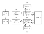
図1は、本発明の実施形態によるネットワークトポロジー及びデータフローを示す図である。 FIG. 1 is a diagram illustrating a network topology and data flow according to an embodiment of the present invention.
図1のネットワークトポロジーを参照すると、送信器(例えば、ホストA)105は、インターネットプロトコル(IP)パケットを幾つかのルータ120及び130を通して最終受信器(ホストB)110に送信する。この時に、送信器105により送信されたIPパケットは、送信器105が送信した順序で最終受信器110に常に到達するものではない。このために、AVコンテンツストリーミングの間に送信順序(例えば、 送信器105によりIPパケットが送信される順序)を示すことは重要である。また、このような送信順序は、データフローで表現される。
Referring to the network topology of FIG. 1, a transmitter (eg, Host A) 105 transmits Internet Protocol (IP) packets through
図1のデータフローを参照すると、アプリケーションステージ140において、図1のデータ150は、実時間プロトコル(Real Time Protocol:RTP)(IETF RFC3550及びRFC3984を参照)を使用してAVコーデックステージで圧縮されたデータをパケット化することにより生成されたRTPパケットデータとして見なされるか、又は図9を参照して後述するMPEGメディアトランスポート(MPEG Media Transport:MMT)トランスポートパケットデータのようにアプリケーションステージ140でのトランスポートプロトコルによりパケット化されたデータを意味する。
Referring to the data flow of FIG. 1, in the application stage 140, the
ここで使用される用語は、次のようにまとめられることができる。
− FEC:エラー又は消去シンボルを訂正するためのエラー訂正コード
− FECフレーム:保護されるFEC符号化情報により生成されたコードワードであり、FECフレームは、情報パート(information part)及びパリティ(リペア)パートを含む。
− シンボル:データの単位であり、複数のビットでのビットのサイズは、シンボルサイズと呼ばれる。
− ソースシンボル:FECフレームの情報パートに含まれる保護されないデータシンボル(Unprotected data Symbol)
− 符号化シンボル:ソースシンボルをFEC符号化することにより生成されるFECフレーム
− リペアシンボル:FEC符号化によりソースシンボルから生成されるFECフレームのパリティパートであり、例えば、FECにより符号化する間にソースシンボルがそのまま保持されるシステマティック符号化の場合に、符号化シンボル=ソースシンボル+リペアシンボルである。
− パケット:ヘッダ及びペイロードを含む送信単位
− ペイロード:送信器から送信されるユーザデータのピース(piece)であり、パケット内に置かれる。
− パケットヘッダ:ペイロードを含むパケットのためのヘッダ
− ソースブロック:1つ以上のソースシンボルを含むシンボルの集合
− リペアブロック:1つ以上のリペアシンボルを含むシンボルの集合
− FECブロック:FECフレームの集合
− FECパケット:FECブロックの送信のためのパケット
− ソースパケット:ソースブロックの送信のためのパケット
− リペアパケット:リペアブロックの送信のためのパケット
− FEC制御パケット:FECパケットを制御するためのパケット
The terms used here can be summarized as follows.
-FEC: error correction code for correcting an error or erasure symbol-FEC frame: a code word generated by FEC encoded information to be protected, and the FEC frame is an information part and parity (repair) Includes parts.
-Symbol: A unit of data, and the bit size of multiple bits is called the symbol size.
-Source symbol: Unprotected data symbol contained in the information part of the FEC frame.
-Encoding symbol: FEC frame generated by FEC encoding the source symbol-Repair symbol: Parity part of the FEC frame generated from the source symbol by FEC encoding, for example during encoding by FEC In the case of systematic coding in which source symbols are held as they are, coding symbols = source symbols + repair symbols.
Packet: A transmission unit including a header and a payload. Payload: A piece of user data transmitted from a transmitter and placed in a packet.
-Packet header: header for a packet including payload-source block: a set of symbols including one or more source symbols-repair block: a set of symbols including one or more repair symbols-FEC block: a set of FEC frames -FEC packet: packet for transmission of FEC block-Source packet: packet for transmission of source block-Repair packet: packet for transmission of repair block-FEC control packet: packet for controlling FEC packet
図2A及び図2Bは、M=1及びM=8の場合について本発明の実施形態によるFEC符号化方法を図式化する図である。特に、図2Aは、M=1の場合の符号化構造を示し、図2Bは、M=8の場合の符号化構造を示す。 2A and 2B are diagrams illustrating the FEC encoding method according to an embodiment of the present invention for M = 1 and M = 8. In particular, FIG. 2A shows an encoding structure when M = 1, and FIG. 2B shows an encoding structure when M = 8.
図2Bを参照すると、ネットワーク上で損失されたデータを復旧するためのFEC符号化方法及びそれによるイン−バンドシグナリング方法は、所定数のシンボルをM(ここで、Mは、1以上の整数)個の第1のソースシンボルに分割し、第1のソースシンボルのそれぞれに対して第1のFEC符号化を実行することにより生成される第1のリペアシンボルを含む第1の符号化シンボルを生成する。その後に、この方法は、M個の符号化シンボルを第2のソースシンボル202に分割し、第2のFEC符号化を実行することにより生成される第2のリペアシンボル201を含む第2の符号化シンボル203を生成する。
Referring to FIG. 2B, an FEC encoding method for recovering data lost on a network and an in-band signaling method thereby recover a predetermined number of symbols M (where M is an integer of 1 or more). Generating first encoded symbols including first repair symbols generated by dividing the first source symbols into first source symbols and performing first FEC encoding on each of the first source symbols To do. Thereafter, the method divides the M encoded symbols into second source symbols 202 and performs a second FEC encoding to generate a second code that includes a
本発明の実施形態によれば、第1のFEC及び第2のFECは、同一のエラー訂正コード又は異なるエラー訂正コードを使用することができる。これらの候補は、RSコード、LDPCコード、ターボコード、ラプターコード、及びXORのような特定のコードに限定されない。 According to an embodiment of the present invention, the first FEC and the second FEC may use the same error correction code or different error correction codes. These candidates are not limited to specific codes such as RS code, LDPC code, turbo code, raptor code, and XOR.
FECが適用されたコンテンツを送信器が受信器に送信する場合に、受信器は、FEC構成関連情報(例えば、送信器が適用したFECのタイプ及び構造のような)を有しなければならず、復号化を実行する場合に、送信器が適用したFEC符号化方式に基づいて復号化を実行することにより損失されたデータを復旧することができる。したがって、本発明の実施形態は、FEC構成関連情報を送信するための方法を含む。また、本発明の実施形態は、受信器が、受信されたパケットがソースシンボルのためのペイロードであるか、又はリペアシンボルのためのペイロードであるかを判定することができるようにするパケット識別方法を含む。 When a transmitter sends FEC applied content to a receiver, the receiver must have FEC configuration related information (eg, such as the type and structure of FEC applied by the transmitter). When performing decoding, it is possible to recover lost data by performing decoding based on the FEC encoding scheme applied by the transmitter. Accordingly, embodiments of the present invention include a method for transmitting FEC configuration related information. Embodiments of the present invention also provide a packet identification method that allows a receiver to determine whether a received packet is a payload for a source symbol or a payload for a repair symbol. including.
このために、本発明の実施形態は、FEC構成関連情報、第1のFEC符号化構成、及び第2のFEC符号化構成を含むFEC制御情報を定義する。例えば、FEC制御情報は、パケット内に含まれることもあり、又はパケットを制御するためのFEC制御パケットに含まれることもある。アウト−バンドシグナリングの場合に、FECが適用されたコンテンツは、実時間トランスポートプロトコル(Real-time Transport Protocol:RTP)プロトコルを使用して送信され、この時に、FEC制御情報は、RTP制御プロトコル(RTP Control Protocol:RTCP)プロトコルを使用して送信されるためにコンテンツ配信のためのプロトコルとは異なる。しかしながら、イン−バンドシグナリングの場合に、FEC制御情報は、FECが適用されたコンテンツのためのRTPパケット内に記憶されて送信されることにより、異なるプロトコルを使用して送信されない。 To this end, the embodiment of the present invention defines FEC control information including FEC configuration related information, a first FEC encoding configuration, and a second FEC encoding configuration. For example, the FEC control information may be included in the packet, or may be included in the FEC control packet for controlling the packet. In the case of out-band signaling, the content to which FEC is applied is transmitted using a Real-time Transport Protocol (RTP) protocol, and at this time, the FEC control information includes an RTP control protocol ( Since it is transmitted using the RTP Control Protocol (RTCP) protocol, it is different from the protocol for content distribution. However, in the case of in-band signaling, the FEC control information is not transmitted using a different protocol by being stored and transmitted in the RTP packet for the content to which FEC is applied.
本発明の実施形態によるFEC構成関連情報については、次のように説明される。 The FEC configuration related information according to the embodiment of the present invention will be described as follows.
(1)符号化構造
− FEC構造:第1のFEC及び/又は第2のFECの適用/不適用
− FECブロック境界−関連情報(以下、“FECブロック境界情報”と呼ばれる):FECブロックの開始位置情報/終了位置情報を示す。
(1) Coding structure-FEC structure: Application / non-application of first FEC and / or second FEC-FEC block boundary-Relevant information (hereinafter referred to as "FEC block boundary information"): Start of FEC block Indicates position information / end position information.
アウト−バンドシグナリングの場合に、FECブロック境界情報は、FEC構成関連情報の送信の後に第1のFECブロックの開始位置情報/終了位置情報を意味する。ここで使用される用語‘位置’は、ネットワークでの位置を意味する。言い換えれば、ネットワーク上でパケット別に送信順序が番号で決定される場合に、その番号は、この位置に対応する。 In the case of out-band signaling, the FEC block boundary information means start position information / end position information of the first FEC block after transmission of FEC configuration related information. The term 'location' used here means a location in the network. In other words, when the transmission order is determined by number for each packet on the network, the number corresponds to this position.
イン−バンドシグナリングの場合に、FECブロック境界情報は、FECブロックを運搬するパケットの中の少なくとも1つのパケットに記憶されるか、又はロバスト性(Robustness)のためにすべてのパケットに記憶される。具体的に、FECブロック境界情報は、図10に示すように、下記に説明するパケットヘッダに送信されることが好ましい。 In the case of in-band signaling, the FEC block boundary information is stored in at least one of the packets carrying the FEC block, or is stored in all packets for robustness. Specifically, as shown in FIG. 10, the FEC block boundary information is preferably transmitted in a packet header described below.
(2)第1のFEC符号化(符号化シンボル1)構成
− FECタイプ関連情報(以下、FECタイプ情報と称する):GF(2^n)上のRS(N,K)コード、GF(2^n)上のLDPC(N,K)コード、GF(2^n)上のターボ(N,K)コード又はGF(2^n)上のラプター(N,K)コードのようなFECコード(ここで、Nは、コード長さを示し、Kは、情報長さを示し、2^nは、シンボルサイズを示す)を示すか、又は、XOR方法を示す。本発明の実施形態によれば、FECタイプ情報は、FECコードのタイプを示すID情報(例えば、0=RS、1=LDPC、及び2=ラプター)とN及びKに関する情報とを含むことができる。
(2) First FEC coding (coding symbol 1) configuration-FEC type related information (hereinafter referred to as FEC type information): RS (N, K) code on GF (2 ^ n), GF (2 FEC code such as LDPC (N, K) code on ^ n), Turbo (N, K) code on GF (2 ^ n) or Raptor (N, K) code on GF (2 ^ n) ( Here, N indicates a code length, K indicates an information length, and 2 ^ n indicates a symbol size) or indicates an XOR method. According to the embodiment of the present invention, the FEC type information may include ID information (for example, 0 = RS, 1 = LDPC, and 2 = raptor) indicating the type of the FEC code, and information on N and K. .
− 短縮関連情報:短縮されたシンボルの個数、短縮パターン(短縮されたシンボルの位置情報)に関する情報を示す。短縮パターンが固定される場合に、短縮パターンに関する情報は省略される。実際に送信される情報の長さがK−sである場合に、s個のパッディングシンボルを追加した後に符号化され、符号化されたN個のシンボルの中で、パッディングされたs個のシンボルは、送信される必要がないので、(N−s)個のシンボルだけが送信される。この場合に、s個のシンボルの短縮が発生する。本発明の実施形態によれば、受信器は、FECタイプ関連情報、FECタイプ関連情報に基づいて実際に送信される情報の長さに関する情報、及びコード内での短縮された位置に関する情報を有することができる。他方、本発明の実施形態によれば、短縮関連情報は、実際に送信される情報の長さK−s、及び短縮パターン(例えば、短縮されたシンボルの位置情報)に関する情報を示す。一例として、短縮パターンが固定される場合に、短縮パターンに関する情報は省略される。 -Shortening-related information: Indicates information on the number of shortened symbols and shortening pattern (shortened symbol position information). When the shortening pattern is fixed, information regarding the shortening pattern is omitted. When the length of information to be actually transmitted is K-s, it is encoded after adding s padding symbols, and s padded among the encoded N symbols. Since no symbols need to be transmitted, only (N−s) symbols are transmitted. In this case, shortening of s symbols occurs. According to an embodiment of the present invention, the receiver has FEC type related information, information about the length of information actually transmitted based on the FEC type related information, and information about a shortened position in the code. be able to. On the other hand, according to the embodiment of the present invention, the shortening related information indicates information regarding the length K-s of the actually transmitted information and the shortening pattern (for example, shortened symbol position information). As an example, when the shortening pattern is fixed, information regarding the shortening pattern is omitted.
− パンクチャーリング関連情報:パンクチャーリングされたシンボルの個数、パンクチャーリングパターン(例えば、パンクチャーリングされたシンボルの位置情報)に関する情報を示す。パンクチャーリングパターンが固定される場合に、パンクチャーリングパターンに関する情報は省略される。符号化されたコードワードのN−Kパリティ内のp個のシンボルが送信の間に抜けている場合に、p個のシンボルのパンクチャーリングが発生した。本発明の実施形態によれば、受信器は、FECタイプ関連情報と、FECタイプ関連情報に基づいて実際に送信されるパリティ(例えば、リペア)シンボルの個数に関する情報と、コード内のパンクチャーリング位置に関する情報とを有することができる。他方、本発明の実施形態によれば、パンクチャーリング関連情報は、実際に送信されるパリティの長さN−K−p、パンクチャーリングパターン(パンクチャーリングされたシンボルの位置情報)に関する情報を示す。一例として、パンクチャーリングパターンが固定される場合に、パンクチャーリングパターンに関する情報は省略される。 -Puncturing related information: indicates information regarding the number of punctured symbols and puncturing patterns (for example, position information of punctured symbols). When the puncturing pattern is fixed, information regarding the puncturing pattern is omitted. P symbol puncturing occurred when p symbols in the NK parity of the encoded codeword were missing during transmission. According to an embodiment of the present invention, the receiver performs FEC type related information, information on the number of parity (eg, repair) symbols actually transmitted based on the FEC type related information, and puncturing in a code. Information about the location. On the other hand, according to the embodiment of the present invention, the puncturing related information includes information on the length NKp of the actually transmitted parity and the puncturing pattern (position information of the punctured symbol). Indicates. As an example, when the puncturing pattern is fixed, information regarding the puncturing pattern is omitted.
FECタイプ関連情報のコード長さ、情報長さ、及び短縮/パンクチャーリング関連情報から、実際に送信される符号化シンボル、ソースシンボル、及びリペアシンボルの個数をそれぞれ確認することができる。FECタイプ関連情報及び短縮/パンクチャーリング関連情報は、コードワードの見方から説明されたが、ここに限定されない。好ましくは、FECタイプ関連情報及び短縮/パンクチャーリング関連情報は、本発明の実施形態の趣旨に基づく情報として解釈されることができる。例えば、FECタイプ関連情報及び短縮/パンクチャーリング関連情報は、FECブロックのソースブロックを運搬するパケットの個数(=K−s)及びパリティブロックを運搬するパケットの個数(=N−K−p)として解釈されることができる。 From the code length of the FEC type related information, the information length, and the shortening / puncturing related information, the number of encoded symbols, source symbols, and repair symbols that are actually transmitted can be confirmed. The FEC type related information and the shortening / puncturing related information have been described from the viewpoint of the code word, but are not limited thereto. Preferably, the FEC type related information and the shortening / puncturing related information can be interpreted as information based on the spirit of the embodiment of the present invention. For example, the FEC type related information and the shortening / puncturing related information include the number of packets carrying the source block of the FEC block (= K−s) and the number of packets carrying the parity block (= N−K−p). Can be interpreted as
− リフティング関連情報:FECコードでの拡張又は縮小を示す値である。ここで使用される用語‘リフティング’は、QC−LDPCの置換ブロック(permutation block)のサイズを調節することによりコードの長さの拡張又は縮小を意味する。本発明の実施形態によれば、一般的なパリティチェックマトリックス(Parity Check Matrix)Hにおいて、各エントリー(entry)を置換ブロックに変更することによりマトリックスを拡張することもリフティングに含まれる。ここで、N個の符号化シンボル1のそれぞれに適用された第1のFECの符号化構成関連情報が異なる場合に、符号化シンボル1のそれぞれに対して第1のFEC符号化構成が必要とされる。
-Lifting related information: a value indicating expansion or contraction in the FEC code. As used herein, the term 'lifting' means extending or reducing the length of the code by adjusting the size of the permutation block of QC-LDPC. According to the embodiment of the present invention, in the general parity check matrix H, the matrix is expanded by changing each entry to a replacement block. Here, when the information related to the coding configuration of the first FEC applied to each of the N coded
この場合に、‘for(i=1;i<=N;i++){i番目の符号化シンボル1構成}’として示すことができる。
In this case, it can be shown as' for (i = 1; i <= N; i ++) {i-th
(3)第2のFEC符号化(符号化シンボル2)構成
本発明の実施形態によれば、第2のFEC符号化構成は、第1のFEC符号化構成と同一である。
(3) Second FEC encoding (encoded symbol 2) configuration According to the embodiment of the present invention, the second FEC encoding configuration is the same as the first FEC encoding configuration.
下記では、本発明の実施形態によるパケット識別方法について説明する。 Hereinafter, a packet identification method according to an embodiment of the present invention will be described.
RTPプロトコルのヘッダは、ペイロードタイプフィールド及びシーケンス番号フィールドを含む。ペイロードタイプフィールド及びシーケンス番号フィールドを有するRTPプロトコル又はこれと類似したトランスポートプロトコルを使用する場合に、このシーケンス番号が1ずつ増加することができるように連続的にかつ順次的に番号を各FECパケットに割り当てる。したがって、FEC構成関連情報及び受信されたパケットのシーケンス番号に基づいて、パケットがソースパケットであるか、リペア1パケットであるか、又はリペア2パケットであるかを確認することができるだけでなく、損失されたパケットがどんなパケットであるかを正確に確認することができる。他方、図10のFECパケットヘッダ1010内のペイロードタイプ情報フィールド1012に基づいて、FECパケット内のペイロードがソースペイロードであるか、リペア1パケットであるか、又はリペア2パケットであるかを確認することができる。
The RTP protocol header includes a payload type field and a sequence number field. When using the RTP protocol having a payload type field and a sequence number field or a similar transport protocol, the FEC packets are sequentially and sequentially numbered so that the sequence number can be incremented by one. Assign to. Therefore, based on the FEC configuration related information and the sequence number of the received packet, not only can the packet be a source packet, a
図10のFECパケットヘッダ1010のパケット長さフィールド1015は、パケットにより実際に運搬されるパケットデータのサイズを示すように構成されることができる。パケット長さフィールド1015を用いてパケット間の境界を確認することができるので、連続したパケットストリームを正確に受信することができる。また、パケットが損失されるとしても、FEC復号化により損失されたパケットのヘッダ情報をまず復旧することにより対応するパケットの長さを把握することができ、これにより、対応するパケットの長さを正確に把握することができる。
The
下記では、本発明の実施形態によるアウト−バンドシグナリング方法について説明する。 Hereinafter, an out-band signaling method according to an embodiment of the present invention will be described.
送信器と受信器間のコンテンツ配信において、コンテンツを配信するためのパケットとこれらのパケットを制御するための制御パケットとに区分される。アウト−バンドシグナリングは、FECブロックを送信するためのパケット(以下、FECパケットと称する)を制御するためのFEC制御パケットを用いてFECパケットに関するFEC構成関連情報を配信することを意味する。送信器がコンテンツを受信器に配信する前に、送信器は、コンテンツに適用されたFEC構成関連情報を受信器があらかじめ認識することができるようにするためにFEC構成関連情報を送信する。このような情報は、FEC構成関連情報の変更の時に送信されなければならない。また、マルチキャスティング(Multicasting)又はブロードキャスティング(Broadcasting)のような複数の受信器がある場合に、FEC構成関連情報は、FEC制御パケットを通して送信されるので、すべての受信器は、コンテンツに適用されたFEC構成関連情報を認識することによりFEC復号化を実行することができる。他方、FEC構成関連情報は、ロバスト性のために周期的に反復して送信されることができる。 Content distribution between a transmitter and a receiver is divided into packets for distributing content and control packets for controlling these packets. Out-band signaling means that FEC configuration related information regarding an FEC packet is distributed using an FEC control packet for controlling a packet for transmitting an FEC block (hereinafter referred to as an FEC packet). Before the transmitter delivers the content to the receiver, the transmitter transmits the FEC configuration related information to enable the receiver to recognize in advance the FEC configuration related information applied to the content. Such information must be transmitted when the FEC configuration related information is changed. Also, if there are multiple receivers such as Multicasting or Broadcasting, the FEC configuration related information is transmitted through FEC control packets, so all receivers are applied to the content. FEC decoding can be executed by recognizing the FEC configuration related information. On the other hand, the FEC configuration related information can be transmitted periodically and repeatedly for robustness.
本発明の実施形態によるアウト−バンドシグナリングの主な目的は、受信器がFECブロックの復号化のための最小の情報である第1のFECの適用/不適用及び/又は第2のFECの適用/不適用をFEC制御情報(例えば、FEC構成関連情報又は符号化構成関連情報)に基づいて判定することができるようにする。したがって、送信器は、4つの場合、すなわち、FECの不適用、第1のFECだけの適用、第2のFECだけの適用、及び第1及び第2のFECの適用の中の1つを決定するか又は選択し、これをFEC制御情報を通して受信器に送信した後に、この決定されたFEC方法を適用することによりコンテンツを配信する。 The main purpose of out-band signaling according to an embodiment of the present invention is to apply / not apply the first FEC and / or apply the second FEC, which is the minimum information for the receiver to decode the FEC block. / Applicability can be determined based on FEC control information (eg, FEC configuration related information or encoding configuration related information). Thus, the transmitter determines one of four cases: FEC non-application, first FEC only application, second FEC only application, and first and second FEC applications. Or select and send it to the receiver through the FEC control information, and then distribute the content by applying this determined FEC method.
本発明の実施形態によれば、FEC制御情報は、FECブロックの開始/終了位置のようなブロック境界情報を追加で含むことができる。FEC方法が予め定められた場合に、受信器は、FECブロックのサイズ又は長さを分かるために、開始/終了位置情報だけでも十分に全FECブロック境界情報を把握することができる。 According to the embodiment of the present invention, the FEC control information may additionally include block boundary information such as the start / end position of the FEC block. When the FEC method is determined in advance, the receiver can sufficiently grasp the total FEC block boundary information only by the start / end position information in order to know the size or length of the FEC block.
本発明の実施形態によれば、様々なタイプの第1のFECが存在する場合又は様々なタイプの第2のFECが存在する場合に、FEC制御情報は、第1のFECタイプ情報及び第2のFECタイプ情報を含むことが好ましい。 According to an embodiment of the present invention, when there are various types of first FECs or when there are various types of second FECs, the FEC control information includes the first FEC type information and the second FEC type information. The FEC type information is preferably included.
送信器が効率的な送信のために短縮又はパンクチャーリングを実行すべきである場合に、FEC制御情報は、短縮及び/又はパンクチャーリング関連情報を含むことが好ましい。 If the transmitter should perform shortening or puncturing for efficient transmission, the FEC control information preferably includes shortening and / or puncturing related information.
また、FEC制御情報は、周期的に送信されることが好ましい。例えば、FEC制御情報は、周期的に反復して送信されることが好ましい。 Further, the FEC control information is preferably transmitted periodically. For example, the FEC control information is preferably transmitted periodically and repeatedly.
図3は、本発明の実施形態によるアウト−バンドシグナリングのためのFEC制御パケットの構造を示す図である。 FIG. 3 is a diagram illustrating a structure of an FEC control packet for out-band signaling according to an embodiment of the present invention.
図3に示すように、FEC制御パケット300は、符号化構成関連情報のためのFEC制御パケット(例えば、ペイロード)及びこのためのヘッダ(図示せず)を含む。
As shown in FIG. 3, the
FEC制御情報は、セッションディスクリプションプロトコル(Session Description Protocol:SDP)に基づく送信器報告が受信器に送信される時に含まれるか、又はRTPを使用する場合にRTCPプロトコルに基づいてRTP制御情報を送信する時に含まれることができる。また、FEC制御情報は、電子サービスガイド(Electric Service Guide:ESG)の送信の間に含まれるか、又は送信の間に、ISO基盤メディアファイルフォーマット(ISO Base Media File Format)を使用する場合に“fpar”ボックス及び“fecr”ボックスに含まれることができ、配信されたコンテンツのタイプ、ネットワーク環境、及び使用中のトランスポートプロトコルにより可能なタイプが様々である。また、FEC制御情報は、図3に示すように、FEC制御ペイロードに含まれることもあるが、これに限定されない。アウト−バンドシグナリングの場合に、FEC制御情報は、符号化構造フィールド310に含まれたFEC構成関連情報、第1のFEC符号化構成320、及び第2のFEC符号化構成330を含む。
FEC control information is included when a transmitter report based on the Session Description Protocol (SDP) is sent to the receiver, or transmits RTP control information based on the RTCP protocol when using RTP Can be included when you do. In addition, the FEC control information is included during transmission of an electronic service guide (ESG), or when an ISO base media file format is used during transmission. There are various types that can be included in the “fpar” box and the “fecr” box and that are possible depending on the type of content delivered, the network environment, and the transport protocol in use. Further, as shown in FIG. 3, the FEC control information may be included in the FEC control payload, but is not limited thereto. In the case of out-band signaling, the FEC control information includes FEC configuration related information included in the
FEC構成関連情報は、第1のFEC及び/又は第2のFECの適用/不適用を示す情報310aを含む。FEC構成関連情報は、FEC構造=00(例えば、符号化なしの場合)、FEC構造=01(例えば、第1のFECだけ適用される場合)、FEC構造=10(例えば、第2のFECだけ適用される場合)、及びFEC構造=11(第1及び第2のFECの両方とも適用される場合)で示される。2つのFEC(第1及び第2のFEC)の中の1つのみ適用される場合は、1つのフィールド値で示されることもある。
The FEC configuration related information includes
FEC構成関連情報は、FECブロック境界情報310bを含む。
The FEC configuration related information includes FEC
第1のFEC符号化構成320は、FECタイプ関連情報320a、リフティング関連情報320b、パンクチャーリング関連情報320c、及び短縮関連情報320dを含む。
The first
リフティング関連情報は、コードの拡張又は縮小を可能にし、短縮/パンクチャーリング関連情報は、与えられたコード内で様々な長さのソースシンボル及びパリティシンボルの対応を可能にする。 Lifting related information allows for code expansion or contraction, and shortening / puncturing related information allows for the correspondence of source symbols and parity symbols of varying lengths within a given code.
第2のFEC符号化構成330は、第1のFEC符号化構成320と同一である。
The second
下記では、本発明の実施形態によるイン−バンドシグナリング方法について説明する。 Hereinafter, an in-band signaling method according to an embodiment of the present invention will be described.
図4は、本発明の実施形態によるイン−バンドシグナリングのためのFEC制御パケットの構造を示す図である。 FIG. 4 is a diagram illustrating a structure of an FEC control packet for in-band signaling according to an embodiment of the present invention.
FEC制御パケットは、FECペイロード400及びヘッダ410を含む。図4には、リペアパケットが示されるが、FEC制御パケットは、これに限定されない。言い換えれば、図4のFEC制御パケット構造は、ロバスト性のためにFECパケットに適用されることができる。図4では、FEC制御情報がヘッダ410に含まれるが、FEC制御パケットは、これに限定されない。言い換えれば、イン−バンドシグナリングのためのFEC制御情報は、ロバスト性のために、送信の間にFECブロックの送信のためのすべてのパケットに記憶されることができる。また、FEC構造のために必要とされる情報だけが送信効率を向上させるように含まれることができる。
The FEC control packet includes an
コンテンツ配信のためのパケットとは識別可能な個別の制御パケット内にFEC構成関連情報を送信するアウト−バンドシグナリングとは異なり、イン−バンドシグナリングは、コンテンツ配信のためのパケット内にFEC構成関連情報を送信することにより、反復的なかつ周期的なFEC制御パケットによるオーバーヘッドを最小にすることができる。また、イン−バンドシグナリングは、受信器がFEC制御パケット送信期間の中間にもコンテンツに適用されたFEC構成関連情報を迅速に把握することができるという長所がある。 Unlike out-band signaling, which transmits FEC configuration related information in a separate control packet that is identifiable from a packet for content delivery, in-band signaling is related to FEC configuration related information in a packet for content delivery. , The overhead due to repetitive and periodic FEC control packets can be minimized. Further, in-band signaling has an advantage that the receiver can quickly grasp the FEC configuration related information applied to the content even in the middle of the FEC control packet transmission period.
本発明によるイン−バンドシグナリングの主な目的は、FECブロックの復号化のための最小情報である第1のFECの適用/不適用及び/又は第2のFECの適用/不適用を示すFEC構成関連情報を送信の間にFECパケット内に記憶させ、これにより、受信器がその情報を把握することができることにある。したがって、4つの場合、すなわち、FECの不適用、第1のFECだけの適用、第2のFECだけの適用、及び第1及び第2のFECの適用の中の1つを決定するか又は選択し、この決定されたFEC方法に基づいてコンテンツをFEC符号化した後に、FECパケットを送信する場合に、送信器は、図4の例に示すように、送信されるFECパケット内にFEC構成関連情報を記憶する。 The main purpose of the in-band signaling according to the present invention is to provide an FEC configuration indicating application / non-application of the first FEC and / or application / non-application of the second FEC, which is the minimum information for decoding of the FEC block. Relevant information is stored in the FEC packet during transmission so that the receiver can grasp the information. Thus, determine or select one of four cases: FEC non-application, first FEC only application, second FEC only application, and first and second FEC applications. Then, when transmitting the FEC packet after the content is FEC encoded based on the determined FEC method, as shown in the example of FIG. Store information.
本発明の実施形態によれば、FEC構成関連情報は、シーケンス番号411、符号化構造フィールド412、及びFEC符号化構成フィールド413を含む。
According to the embodiment of the present invention, the FEC configuration related information includes a sequence number 411, an
FEC構成関連情報は、第1のFEC及び/又は第2のFECの適用/不適用を示す情報412aを含む。FEC構成関連情報は、FEC構造=00(例えば、符号化なしの場合)、FEC構造=01(例えば、第1のFECだけ適用される場合)、FEC構造=10(例えば、第2のFECだけ適用される場合)、及びFEC構造=11(第1及び第2のFECの両方とも適用される場合)で示される。具体的に、FEC構成関連情報は、送信の間に、FECブロックのためのFECパケットの中の少なくとも1つのパケットに記憶される。より具体的に、パケット損失に対するロバスト性のために、FEC構成関連情報は、送信の間に、すべてのパケットに記憶されるか、又はリペアパケット又はソースパケットに記憶されることができる。例えば、FEC構成関連情報は、送信の間に、パケットヘッダに記憶されるか、又は、もっと具体的に、リペアパケットヘッダに記憶されることができる。FEC構成関連情報が送信の間にリペアパケットヘッダに記憶される場合に、ソースパケットは、FECが適用されない場合と同一にソースシンボルを送信するための既存のパケット形態で送信されることができるので、FECが適用されないシステムとの互換性を保持することができる。
The FEC configuration related information includes
好ましくは、FEC構成関連情報は、FECブロックの開始/終了位置のようなFECブロック境界情報412bを追加で含むことができる。FEC方法が予め定められる場合に、受信器は、FECブロックのサイズ又は長さを分かるために、FECブロックの開始/終了位置情報だけでも十分に全FECブロック境界情報を把握することができる。 Preferably, the FEC configuration related information may additionally include FEC block boundary information 412b such as a start / end position of the FEC block. When the FEC method is determined in advance, the receiver can sufficiently grasp all the FEC block boundary information only by the start / end position information of the FEC block in order to know the size or length of the FEC block.
好ましくは、FEC構成関連情報は、符号化構造フィールド412に含まれ、次のFECブロックに関するFEC構成関連情報が現在のFECブロックに基づいて変更されるか否かを示すFEC構成連続フラグ412cを含むことができる。
Preferably, the FEC configuration related information is included in the
本発明の実施形態によれば、FEC符号化構成関連情報413は、FEC符号化構成フィールドに含まれ、幾つかの第1のFECタイプ又は幾つかの第2のFECタイプが存在する場合に、第1のFECタイプ情報及び第2のFECタイプ情報を含むFECタイプ情報413aを含むことができる。 According to an embodiment of the present invention, the FEC encoding configuration related information 413 is included in the FEC encoding configuration field, and when there are some first FEC types or some second FEC types, FEC type information 413a including first FEC type information and second FEC type information may be included.
本発明の実施形態によれば、FEC符号化構成関連情報は、与えられたFECタイプ情報に対して、送信の間にコードを拡張するか又は縮小するためにリフティング関連情報413bを含むことができる。 According to an embodiment of the present invention, the FEC coding configuration related information may include lifting related information 413b to extend or reduce the code during transmission relative to the given FEC type information. .
本発明の実施形態によれば、FEC符号化構成関連情報は、送信器が効率的な送信のために短縮又はパンクチャーリングを実行する場合に、短縮関連情報413c及び/又はパンクチャーリング関連情報413dを含むことができる。 According to an embodiment of the present invention, the FEC coding configuration related information may be shortened related information 413c and / or punctured related information when the transmitter performs shortening or puncturing for efficient transmission. 413d can be included.
リフティング関連情報413bは、コードの拡張又は縮小を可能にし、短縮/パンクチャーリング関連情報は、与えられたコード内で様々な長さのソースシンボル及びパリティシンボルの対応を可能にする。 Lifting related information 413b enables code expansion or contraction, and shortening / puncturing related information allows for the correspondence of source symbols and parity symbols of various lengths within a given code.
図5は、本発明の実施形態によるアウト−バンドシグナリングのためのシステム構成を示す図である。 FIG. 5 is a diagram illustrating a system configuration for out-band signaling according to an embodiment of the present invention.
ディジタルカメラを用いて撮影したロー(Raw)AVストリーム1は、ローAVコンテンツ501として有効に記憶される。ローAVコンテンツ501(例えば、ローAVストリーム1)は、AVコーデックエンコーダ503に送信される。
A
AVコーデックエンコーダ503は、オーディオコーデックエンコーダ及びビデオコーデックエンコーダを使用して入力されるローAVストリーム1を圧縮することによりAVストリーム2を生成し、AVストリーム2をトランスポートプロトコルパケタイザ(Transport Protocol Packetizer)505に出力する。
The
トランスポートプロトコルパケタイザ505は、圧縮されたAVストリーム2をペイロード単位に分け、パケットヘッダをペイロードのそれぞれに付加することによりパケット化されたストリームを作る。FECを適用する場合に、トランスポートプロトコルパケタイザ505は、関連する符号化構造及び/又は符号化構成関連情報によりパケットストリームを所定数のソースパケットに分ける。その後に、トランスポートプロトコルパケタイザ505は、ソースパケットのヘッダを除外したソースペイロードを含むソースブロック3をFECエンコーダ507に入力する。
The
FECエンコーダ507は、符号化構造及び/又は符号化構成関連情報に合うようにソースブロック3を符号化し、FECブロック4をトランスポートプロトコルパケタイザ505に出力する。
The
トランスポートプロトコルパケタイザ505は、入力されたFECブロック4内の各ペイロードにパケットヘッダを付加することによりFEC符号化されたパケットストリーム7を送信し、図3で説明したように、FEC制御パケット(ペイロード又はヘッダ)内にアウト−バンドシグナリングのためのFEC構成関連情報を記憶する。
The
コンテンツに適用された符号化構造及びFEC符号化構成関連情報は、FEC制御パケット5に記憶され、コンテンツの配信の前に受信器にあらかじめ送信され、したがって、受信器がコンテンツに適用されるFEC構造及び/又はFEC符号化構成関連情報を把握することができるようにする。
The coding structure applied to the content and the FEC coding configuration related information are stored in the
本発明の実施形態によれば、FEC制御パケット内のFEC構造及びリペアパケットヘッダ内のFEC構造のための2ビットを割り当てることにより、b0は、第1のFECの適用/不適用を示し、b1は、第2のFECの適用/不適用を示す。言い換えれば、ビットは、符号化なしに対応するFEC構造=00、第1のFECだけの適用に対応するFEC構造=01、第2のFECだけの適用に対応するFEC構造=10、及び第1及び第2のFECの適用に対応するFEC構造=11で示す。 According to an embodiment of the present invention, by assigning 2 bits for the FEC structure in the FEC control packet and the FEC structure in the repair packet header, b0 indicates the application / non-application of the first FEC, and b1 Indicates application / non-application of the second FEC. In other words, the bits are FEC structure = 00 corresponding to no coding, FEC structure = 01 corresponding to application of only the first FEC, FEC structure = 10 corresponding to application of the second FEC only, and first And FEC structure = 11 corresponding to the application of the second FEC.
送信の間に、FECブロック境界情報は、FEC制御パケットの送信の直後に送信されるFEC符号化ブロックの第1のペイロードのためのパケットのシーケンス番号を指定する。 During transmission, the FEC block boundary information specifies the sequence number of the packet for the first payload of the FEC encoded block that is transmitted immediately after transmission of the FEC control packet.
トランスポートプロトコルデパケタイザパケタイザ(Transport Protocol De-packetizer)509は、FEC制御パケット6を受信し、受信されるコンテンツのFEC構成関連情報に基づいてFEC復号化を準備する。コンテンツのサービスの間にサービングに参加した受信器は、受信されたパケットのリペアパケットヘッダからFEC構成関連情報を取得し、これに基づいてFEC復号化を実行する。
The transport protocol depacketizer (Transport Protocol De-packetizer) 509 receives the
トランスポートプロトコルデパケタイザ509は、受信されたパケットストリームからパケットを送信順序で再配列した後に、パケットからヘッダを除去することによりペイロードストリームを作る。FECが適用される場合に、トランスポートプロトコルデパケタイザ509は、コンテンツに適用されたFEC構成関連情報に基づいて受信されたFEC符号化されたパケットストリーム8から損失されたパケットの位置情報及びFECブロック境界情報を把握する。また、トランスポートプロトコルデパケタイザ509は、この損失されたパケットの位置情報及びFECブロック境界情報に基づいて、各FECブロックに対応する損失されたペイロードの位置情報及び受信されたFECブロック9をFECデコーダ511に入力する。
The
また、パケット識別方法のように、シーケンス番号フィールドがトランスポートパケットのヘッダ内に構成され、パケット送信の間に、番号がパケット送信順序に合うように連続して割り当てられる場合に、トランスポートプロトコルデパケタイザ509は、受信の間に、シーケンス番号に基づいて送信パケットの順序に合うように再配列し、損失されたパケットの位置(例えば、番号)を把握することができる。
Also, as in the packet identification method, when the sequence number field is configured in the header of the transport packet and the numbers are continuously assigned so as to match the packet transmission order during packet transmission, the transport protocol depa During reception, the
FECデコーダ511は、FEC復号化を通して損失されたペイロードの位置情報及び受信されたFECブロックから損失されたペイロードを復旧することによりソースブロック10を復元し、これをトランスポートプロトコルデパケタイザ509に入力する。
The
トランスポートプロトコルデパケタイザ509は、入力されたソースブロックをストリーム11に変換し、ストリーム11をAVコーデックデコーダ513に入力する。
The
AVコーデックデコーダ513は、オーディオコーデックデコーダ及びビデオコーデックデコーダを用いてAVコンテンツを復号化し、この復号化されたAVコンテンツをストリーム12としてディスプレー515に入力する。
The
ディスプレー515は、復号化されたAVコンテンツをディスプレーする。
The
本発明の実施形態によれば、FECが適用されない(すなわち、FEC構造=“符号化なし”)場合に、トランスポートプロトコルパケタイザ505がソースブロック3をFECエンコーダ507に入力する過程1と、FECエンコーダ507が符号化構造及び/又は符号化構成関連情報に合うようにソースブロックを符号化し、FECブロック4をトランスポートプロトコルパケタイザ505に出力する過程2と、受信器での過程1及び過程2の逆過程が省略される。
According to an embodiment of the present invention, when FEC is not applied (ie, FEC structure = “no encoding”), the
FEC制御パケット5及び6は、コンテンツ配信の間に周期的に反復して送信される。FECが適用される場合に、FEC構成関連情報に含まれたFECブロック境界情報は、FEC制御パケットの送信の直後に送信されるFEC符号化ブロックの第1のペイロードのためのパケットのシーケンス番号を指定する。
パケットヘッダ7及び8内のFECブロック境界情報は、送信の間に、対応するFECブロックの第1のペイロードのためのパケットのシーケンス番号を指定する。
The FEC block boundary information in the
FECブロック境界情報及びFEC符号化構成関連情報は、送信器と受信器間で相互に約束されている場合に(例えば、FECのFECタイプが送信器と受信器間で相互に約束されており、リフティング値、送信情報シンボルの長さ、及びリペアシンボルの長さが固定される場合に)、省略されて送信される。 The FEC block boundary information and the FEC coding configuration related information are mutually promised between the transmitter and the receiver (for example, the FEC type of FEC is mutually promised between the transmitter and the receiver, When the lifting value, the length of the transmission information symbol, and the length of the repair symbol are fixed, the transmission is omitted.
本発明の実施形態によれば、FECタイプ情報に基づく各コードがパリティチェックマトリックスを使用する場合に、そのマトリックスは予め約束されており、RSコードを使用する場合に、その生成多項式(Generator Polynomial)は、予め定められているものと仮定する。例えば、FECタイプ情報が“GF(2)上のLDPC(8000,6400)コード”を示す場合に、送信器及び受信器は、コードのマトリックスHを共有するものと仮定する。FECタイプ情報が“GF(2^8)上のRS(255,51)コード”を示す場合に、送信器及び受信器は、RSコードの生成多項式g(x)を共有するものと仮定する。このような仮定は、送信器と受信器間の約束又は仕様で定められることにより可能である。 According to an embodiment of the present invention, when each code based on FEC type information uses a parity check matrix, the matrix is promised in advance, and when using an RS code, its generator polynomial is generated. Is assumed to be predetermined. For example, if the FEC type information indicates “LDPC (8000, 6400) code on GF (2)”, it is assumed that the transmitter and receiver share a matrix H of codes. When the FEC type information indicates “RS (255, 51) code on GF (2 ^ 8)”, it is assumed that the transmitter and the receiver share the RS code generator polynomial g (x). Such assumptions are possible as defined by the promise or specification between the transmitter and receiver.
図6は、本発明の実施形態によるイン−バンドシグナリングのためのシステム構成を示す図である。 FIG. 6 is a diagram illustrating a system configuration for in-band signaling according to an embodiment of the present invention.
本発明の実施形態によれば、図6のイン−バンドシグナリングのためのシステムにおいて、過程5及び6は省略され、図5の過程7乃至12は、図6の過程5乃至10にそれぞれ対応し、この過程と同一である。しかしながら、図6の過程5及び6において、提案されたFEC構成情報は、送信の間にFECパケットのパケットヘッダに記憶される。
According to the embodiment of the present invention, steps 5 and 6 are omitted in the system for in-band signaling of FIG. 6, and
本発明の実施形態は、ソースパケットのペイロードがFEC保護されているという仮定に基づいて説明されたが、これに限定されず、ソースパケットに対するFEC符号化を実行した後にヘッダをリペアブロックに付加することによりFECパケットを生成し、FECパケットを送信することを含む。例えば、この場合に、トランスポートパケタイザは、ソースブロックのためのパケットヘッダにFEC制御情報を保存した後に符号化を実行し、リペアブロックのためのパケットのヘッダにも同一の情報を保存するか又は必要な情報を保存する。 Although the embodiment of the present invention has been described based on the assumption that the payload of the source packet is FEC protected, the present invention is not limited thereto, and a header is added to the repair block after performing FEC encoding on the source packet. Generating an FEC packet and transmitting the FEC packet. For example, in this case, the transport packetizer performs the encoding after storing the FEC control information in the packet header for the source block, and stores the same information in the header of the packet for the repair block. Or save necessary information.
図5及び図6を参照してAVデータが説明されたが、本発明の実施形態は、これに限定されない。本発明の実施形態は、ハイブリッドコンテンツ配信(Hybrid Content Delivery)のようにAVデータ及びファイルデータがともに送信される場合も適用されることができる。この場合に、ソースブロックは、AVデータ及びファイルデータを含む。 Although the AV data has been described with reference to FIGS. 5 and 6, the embodiment of the present invention is not limited to this. The embodiment of the present invention can also be applied to the case where both AV data and file data are transmitted, such as hybrid content delivery. In this case, the source block includes AV data and file data.
図7は、本発明の実施形態による送信方法を示すフローチャートである。 FIG. 7 is a flowchart illustrating a transmission method according to an embodiment of the present invention.
ステップ701において、送信器は、本発明の実施形態によるFEC制御情報を生成する。本発明の実施形態に従って、FEC制御情報は、FEC構成関連情報、第1のFEC符号化構成関連情報、及び第2のFEC符号化構成関連情報を含む。しかしながら、本発明の実施形態は、これに限定されない。アウト−バンドシグナリングの場合に、FEC構成関連情報、第1のFEC符号化構成関連情報、及び第2のFEC符号化構成関連情報は、図3に示すように、FEC制御パケット300に含まれる。しかしながら、イン−バンドシグナリングの場合に、FEC構成関連情報、第1のFEC符号化構成関連情報、及び第2のFEC符号化構成関連情報は、図4に示すように、リペアパケット(例えば、ヘッダ及びリペアペイロードのすべて)に含まれる。
In
ステップ703において、送信器は、生成されたFEC構成関連情報、第1のFEC符号化構成関連情報、及び第2のFEC符号化構成関連情報を含むパケットを生成し、このパケットを受信器に送信する。
In
図8は、本発明の実施形態による受信方法を示すフローチャートである。 FIG. 8 is a flowchart illustrating a receiving method according to an embodiment of the present invention.
ステップ801において、受信器は、送信器からパケットを受信し、受信されたパケットを復調する。ステップ803において、受信器は、復調されたパケット(FEC制御パケット又はリペアパケット)からFEC構成関連情報、第1のFEC符号化構成関連情報、及び第2のFEC符号化構成関連情報を取得し、受信されたパケット関連情報を認識する。パケット関連情報は、それぞれのFECブロックに対応する損失されたペイロードの位置情報及び受信されたFECブロック情報を含む。したがって、受信器は、パケット情報に基づいて、受信されたパケットがソースシンボルのためのパケットであるか、又はリペアシンボルのためのパケットであるかを判定することができる。また、受信器は、送信器により適用されたFECのタイプ及び構造を把握することができる。ステップ805において、受信器は、このパケットを復号する。
In
本発明の実施形態は、配信されるコンテンツ(AVデータ、ファイル、テキストなどを含む)に第1のFECの適用/不適用及び第2のFECの適用/不適用を示すFEC構成関連情報を含む。アウト−バンドシグナリングの場合に、FEC構成関連情報のためのプロトコルは、コンテンツ配信のためのプロトコルとは識別されることが好ましい。FECが適用されたコンテンツがRTPプロトコルを使用して配信される場合に、FEC制御情報は、RTCPプロトコルを使用して送信されるためにコンテンツ配信のためのRTPプロトコルとは異なる。しかしながら、イン−バンドシグナリングの場合に、FEC制御情報は、送信の間にFECが適用されたコンテンツのためのRTPパケット内に記憶され、これにより、異なるプロトコルを使用して送信されない。MMTトランスポートプロトコルを使用して送信される場合に、アウト−バンドシグナリングのためのFEC制御情報は、MMTトランスポート制御プロトコルにより送信される。 The embodiment of the present invention includes FEC configuration related information indicating application / non-application of the first FEC and application / non-application of the second FEC to content to be distributed (including AV data, files, texts, and the like). . In the case of out-band signaling, the protocol for FEC configuration related information is preferably identified from the protocol for content delivery. When content to which FEC is applied is distributed using the RTP protocol, the FEC control information is different from the RTP protocol for content distribution because it is transmitted using the RTCP protocol. However, in the case of in-band signaling, the FEC control information is stored in RTP packets for content to which FEC has been applied during transmission, and thus is not transmitted using a different protocol. When transmitted using the MMT transport protocol, FEC control information for out-band signaling is transmitted by the MMT transport control protocol.
本発明の実施形態によれば、FEC構成関連情報は、コンテンツをペイロードに分け、これをFEC符号化することにより得られたFECブロックのブロック境界情報を含むことができる。アウト−バンドシグナリングの場合に、ブロック境界情報は、FEC構成情報の送信の直後に1番目のFECブロックの開始パケット/終了パケットの番号を含む。FEC構成関連情報は、FECタイプ関連情報、リフティング関連情報、短縮関連情報、及びパンクチャーリング関連情報の中の少なくとも1つを含む。第1のFECのためのFECタイプ情報及び第2のFECのためのFECタイプ情報の中の1つは、GF(2^n)上のRS(N,K)コード、GF(2)上のLDPC(N,K)コード、GF(2)上のターボ(N,K)コード、GF(2)上のラプター(N,K)コード、及びGF(2^m)上のラプターQ(N,K)コードの中の少なくとも1つを含み、ここで、n及びmは、1より大きい整数である。 According to the embodiment of the present invention, the FEC configuration related information may include block boundary information of FEC blocks obtained by dividing content into payloads and FEC encoding them. In the case of out-band signaling, the block boundary information includes the number of the start packet / end packet of the first FEC block immediately after transmission of the FEC configuration information. The FEC configuration related information includes at least one of FEC type related information, lifting related information, shortening related information, and puncturing related information. One of the FEC type information for the first FEC and the FEC type information for the second FEC is an RS (N, K) code on GF (2 ^ n), on GF (2) LDPC (N, K) code, turbo (N, K) code on GF (2), raptor (N, K) code on GF (2), and raptor Q (N, K on GF (2 ^ m) K) includes at least one of the codes, where n and m are integers greater than one.
イン−バンドシグナリングの場合に、FEC構成関連情報は、送信の間に、FEC保護(‘符号化なし’を含む)が行われたコンテンツの配信のためのパケット内に記憶される。第1のFECが配信されるコンテンツに適用されるか又は第2のFECがコンテンツに適用されるかを示すFEC構成関連情報のためのプロトコルがコンテンツに適用されるために、FECが適用されたコンテンツ(‘符号化なし’を含む)のためのプロトコルとは識別可能なプロトコルを使用するか又は同一のプロトコルを使用することができる。また、FEC構成関連情報は、FECが適用されたコンテンツの配信のためのパケット内に送信される。 In the case of in-band signaling, the FEC configuration related information is stored in a packet for delivery of content with FEC protection (including 'no encoding') during transmission. FEC was applied because the protocol for FEC configuration related information indicating whether the first FEC is applied to the content to be delivered or the second FEC is applied to the content is applied to the content A protocol identifiable as the protocol for content (including 'no encoding') can be used, or the same protocol can be used. Further, the FEC configuration related information is transmitted in a packet for distributing contents to which FEC is applied.
図9は、本発明の実施形態によるMMTシステム構造を示す図である。 FIG. 9 is a diagram illustrating an MMT system structure according to an embodiment of the present invention.
図9の左側は、MMTシステム構造を示し、図9の右側は、配信機能の詳細構造を示す図である。 The left side of FIG. 9 shows the MMT system structure, and the right side of FIG. 9 shows the detailed structure of the distribution function.
メディアコーディングレイヤー905は、オーディオ及び/又はビデオデータを圧縮し、圧縮されたデータをカプセル化機能レイヤー910に送信する。 The media coding layer 905 compresses the audio and / or video data and sends the compressed data to the encapsulation function layer 910.
カプセル化機能レイヤー910は、圧縮されたオーディオ/ビデオデータをファイルフォーマットと類似した形態でパッケージとして生成し、パケット化されたデータを配信機能920に出力する。 The encapsulation function layer 910 generates compressed audio / video data as a package in a form similar to the file format, and outputs the packetized data to the distribution function 920.
配信機能920は、カプセル化機能レイヤー910の出力をMMTペイロードフォーマットに変換した後に、MMTトランスポートパケットヘッダを付加し、これをMMTトランスポートパケットの形態でトランスポートプロトコル930に出力するか、又は、カプセル化機能レイヤー910の出力を既存のRTPプロトコルを使用してRTPパケットの形態でトランスポートプロトコル930に出力する。その後に、トランスポートプロトコル930は、その入力をUDP及びTCPトランスポートプロトコルの中の1つに変換した後に、これをインターネットプロトコル940に送信する。 The distribution function 920 converts the output of the encapsulation function layer 910 into the MMT payload format and then adds an MMT transport packet header and outputs this to the transport protocol 930 in the form of an MMT transport packet, or The output of the encapsulation function layer 910 is output to the transport protocol 930 in the form of an RTP packet using the existing RTP protocol. The transport protocol 930 then converts the input to one of the UDP and TCP transport protocols and sends it to the Internet protocol 940.
最終的に、インターネットプロトコル940は、トランスポートプロトコル930の出力をIPパケットに変換する。 Finally, the Internet protocol 940 converts the output of the transport protocol 930 into an IP packet.
提案されたFECパケットは、MMTペイロードフォーマット、MMTトランスポートパケット、及びRTPパケットの中の少なくとも1つの形態で送信されることができる。 The proposed FEC packet may be transmitted in at least one form among an MMT payload format, an MMT transport packet, and an RTP packet.
図10は、本発明の実施形態によるイン−バンドシグナリングのためのFEC制御パケットの構造を示す図である。 FIG. 10 is a diagram illustrating a structure of an FEC control packet for in-band signaling according to an embodiment of the present invention.
イン−バンドシグナリングの場合に、FEC制御情報は、FECブロックを運搬するパケットの中の少なくとも1つのパケットに記憶されるか、又はロバスト性のためにすべてのパケットに記憶される。図10に示すように、FEC制御情報は、パケットヘッダ1010を通して送信されることが好ましいが、これに限定されない。
In the case of in-band signaling, the FEC control information is stored in at least one of the packets carrying the FEC block, or stored in all packets for robustness. As shown in FIG. 10, the FEC control information is preferably transmitted through a
FEC制御パケットは、図10に示すように、符号化構成関連情報の符号化のためのFEC制御ペイロード1000及びヘッダ1010を含む。
As shown in FIG. 10, the FEC control packet includes an
パケットヘッダ1010は、ペイロードタイプ1012、シーケンス番号1014、パケット長さ1015、符号化構造フィールド1016、及びFEC符号化構成フィールド1018を含む。
The
ペイロードタイプ1012は、FECパケット内のペイロードがソースペイロードであるか、リペア−1パケットであるか、又はリペア−2パケットであるかを示す。
The
シーケンス番号1014は、1ずつ増加するように各FECパケットに連続的にかつ順次的に割り当てられる番号を示す。
The
パケット長さ1015は、対応するパケットが実際に運搬するパケットデータのサイズを示す。イン−バンドシグナリングの場合に、アウト−バンドシグナリングの場合とは異なり、FECパケットヘッダのパケット長さフィールド1015が追加される。パケット長さ1015を使用してパケット間の境界を分かるために、連続したパケットストリームを正確に受信することができる。また、パケット長さ1015を使用してパケットが損失されるとしても、FEC復号化により損失されたパケットのヘッダ情報をまず復旧し、このヘッダ情報により対応するパケットの長さを把握した後に、対応するパケットの長さ情報を正しく得ることができる。
The
符号化構造フィールド1016は、第1のFECの適用/不適用及び/又は第2のFECの適用/不適用を示すFEC構成関連情報1016a、FECブロック境界関連情報1016b、及びFEC構成連続フラグ1016cを含む。
The coding structure field 1016 includes FEC configuration related
FEC符号化構成フィールド1018は、FECタイプ関連情報1018a、リフティング関連情報1018b、短縮関連情報1018c、及びパンクチャーリング関連情報1018dを含む。
The FEC
下記では、本発明の実施形態によるアプリケーションレイヤー順方向エラー訂正(AL−FEC)シグナリング方法について説明する。 Hereinafter, an application layer forward error correction (AL-FEC) signaling method according to an embodiment of the present invention will be described.
1.損失モデル
AL−FECのためのチャネルモデルについて、2種類の損失モデルは、下記のように仮定することができる。
1. Loss models For the channel model for AL-FEC, two types of loss models can be assumed as follows.
通常、ネットワークでの消去は、ランダムにだけでなくバースト方式でも発生するために、ランダム+バースト消去チャネルモデルを仮定することが好ましい。 Since erasure in the network usually occurs not only randomly but also in a burst system, it is preferable to assume a random + burst erasure channel model.
DVB AL−FECブルーブック(Bluebook)に明示されたREIN消去チャネルは、ランダム消去チャネルと結合されることができる。反復電気インパルス雑音(REIN)チャネルは、ディジタル加入者回線(Digital Subscriber Line:DSL)ラインで8msの固定されたタイムバースト消去(fixed time burst erasure)を引き起こすことがある。 The REIN erase channel specified in the DVB AL-FEC Bluebook can be combined with a random erase channel. A repetitive electrical impulse noise (REIN) channel can cause a fixed time burst erasure of 8 ms on a Digital Subscriber Line (DSL) line.
1.1 ランダム+REIN消去チャネルモデル
− 反復電気インパルス雑音(REIN):固定されたタイムバースト消去(8ms)
1.1 Random + REIN cancellation channel model-Repetitive electrical impulse noise (REIN): fixed time burst cancellation (8 ms)
図11は、本発明の実施形態による2状態ギルバート−エリオット消去チャネル(Gilbert-Elliot Erasure Channel:GEEC)モデルの一例を示す図である。 FIG. 11 is a diagram illustrating an example of a two-state Gilbert-Elliot Erasure Channel (GEEC) model according to an embodiment of the present invention.
2状態ギルバート−エリオット消去チャネルモデルは、図11に示すように、良い状態1100及び悪い状態1200を含む。図11において、良い状態1100は、低い損失状態を示し、悪い状態1200は、バースト消去を誘発させる高い損失状態を示す。
The two-state Gilbert-Elliot cancellation channel model includes a
1.2 2状態ギルバート−エリオット消去チャネル(GEEC)モデル
− 良い状態:ランダム消去チャネル(低い損失状態)
− 悪い状態:バースト消去チャネル(高い損失状態)
1.2 Two-state Gilbert-Eliot erasure channel (GEEC) model-Good state: Random erasure channel (low loss state)
– Bad condition: burst erase channel (high loss condition)
2.2ステージFEC符号化構造でのシミュレーション
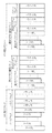
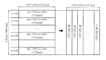
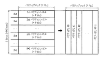
図12A及び図12Bは、本発明の実施形態による1ステージ及び2ステージFEC符号化構造を示す図である。特に、図12Aは、1ステージFEC符号化構造を示し、図12Bは、2ステージFEC符号化構造を示す。
2.2 Simulation with a Stage FEC Coding Structure FIGS. 12A and 12B are diagrams illustrating a one stage and a two stage FEC coding structure according to an embodiment of the present invention. In particular, FIG. 12A shows a one-stage FEC encoding structure, and FIG. 12B shows a two-stage FEC encoding structure.
1ステージFEC符号化構造は、P=P1+P2に対応するFECパリティを各サブブロックに付加する。 The one-stage FEC coding structure adds an FEC parity corresponding to P = P1 + P2 to each sub-block.
他方、2ステージFEC符号化構造は、P1 FECパリティを各サブブロックに付加し、P2 FECパリティをM個のサブブロック全体を含むソースブロックに付加する。 On the other hand, the two-stage FEC coding structure adds a P1 FEC parity to each subblock and adds a P2 FEC parity to a source block that includes all M subblocks.
図13乃至図18は、本発明の実施形態によるランダム+REINチャネル上で2ステージFEC符号化構造及び1ステージFEC符号化構造に対するシミュレーション結果を示す図である。 13 to 18 are diagrams illustrating simulation results for a two-stage FEC coding structure and a one-stage FEC coding structure on a random + REIN channel according to an embodiment of the present invention.
ハイブリッド配信サービス、例えば、AVストリーミング及びファイル配信を同一のストリーム内で送信する場合に、図面に示すように、それぞれのAVデータ及びファイルデータが共に送信される。通常、P1に対応するFECパリティがAVデータのために必要とされる場合に、ファイルデータは、AVデータより高いFEC性能を要求するので、AVデータ及びファイルデータを同時にストリーミングする場合に、ファイルデータの要求性能に合うようにP=P1+P2に対応するFECパリティを要求する。しかしながら、これは、ランダム消去が発生するチャネル環境では有効であるが、バースト消去が発生するチャネル環境では有効でないために、さらに効率的な方法が要求される。通常に、バースト消去を訂正するための方法では、非常に長いコードを使用するか、又はインターリービングを通してバースト消去をランダム消去にスイッチングすることにより復号化性能を向上させることができる。しかしながら、上記の通りに、長いコードを使用するか又はインターリービングを通してバースト消去を訂正する場合には、AVデータの増加を引き起こすことがある。したがって、バースト消去が発生する環境でハイブリッド配信サービスが行われる場合には、効率的な方法が要求される。 When a hybrid distribution service, for example, AV streaming and file distribution are transmitted in the same stream, each AV data and file data is transmitted together as shown in the drawing. Normally, when FEC parity corresponding to P1 is required for AV data, file data requires higher FEC performance than AV data. Therefore, when AV data and file data are simultaneously streamed, file data The FEC parity corresponding to P = P1 + P2 is requested so as to meet the required performance. However, this is effective in a channel environment where random erasure occurs, but is not effective in a channel environment where burst erasure occurs. Therefore, a more efficient method is required. Typically, methods for correcting burst erasures can improve decoding performance by using very long codes or switching burst erasures to random erasures through interleaving. However, as described above, using a long code or correcting burst erasure through interleaving may cause an increase in AV data. Therefore, when a hybrid distribution service is performed in an environment where burst erasure occurs, an efficient method is required.
図13乃至図18は、1ステージFEC符号化構造のためにP=P1+P2に対応するFECパリティを各サブブロックに付加し、2ステージFEC符号化構造のためにP1 FECパリティを各サブブロックに付加し、P2 FECパリティをM個のサブブロックを含むソースブロックに付加した後に、ランダム+REINチャネル環境の下で実行されたシミュレーションの結果を示す図である。 FIGS. 13 to 18 show that a FEC parity corresponding to P = P1 + P2 is added to each subblock for a one-stage FEC coding structure, and a P1 FEC parity is added to each subblock for a two-stage FEC coding structure. FIG. 10 is a diagram illustrating a result of a simulation performed under a random + REIN channel environment after adding a P2 FEC parity to a source block including M sub-blocks.
以下は、シミュレーションパラメータを整理したものである。
2.1 シミュレーションパラメータ
− データレート:8Mbps
− ペイロードサイズ:1000バイト
− コード:アイデアルコード
− 全オーバーヘッド(Overall overhead):20%(P=P1+P2)
− 1ステージP:20%
− 2ステージP1−P2:15%−5%
− サブブロック長さ(K):200、400
− サブブロックの個数(M):K=200の場合に32であり、K=400の場合に16である。
− ブロック期間:サブブロック長さ200の場合に200msであり、サブブロック長さ400の場合に400msである。
− ランダム消去:パケット消去率(PER)=0〜20%
− バースト消去:パケット消去率(PER)を有するREIN(8ms)=0.0001、0.001、0.01
The following is a summary of the simulation parameters.
2.1 Simulation parameters-Data rate: 8 Mbps
− Payload size: 1000 bytes − Code: Ideal code − Overall overhead: 20% (P = P1 + P2)
-1st stage P: 20%
-2 stage P1-P2: 15% -5%
-Subblock length (K): 200, 400
Number of sub-blocks (M): 32 when K = 200 and 16 when K = 400.
Block period: 200 ms for a subblock length of 200 and 400 ms for a subblock length of 400.
-Random erasure: Packet erasure rate (PER) = 0-20%
Burst erasure: REIN (8 ms) with packet erasure rate (PER) = 0.0001, 0.001, 0.01
ここで使用される‘サブブロック長さ’は、サブブロックを構成するペイロードの個数を意味する。ペイロードのサイズが1000バイトとして設定される場合に、サブブロック長さ200は、8Mbpsのデータレートを要求するサービスで約200msのFECブロック期間を有し、サブブロック長さ400は、400msのFECブロック期間を有する。これらの状況から、REIN(8ms)バースト消去が1回発生する時に、どれくらいのペイロードがFECブロックから消去されるかを計算することができる。このような方式でシミュレーションを実行する。
The “sub-block length” used here means the number of payloads constituting the sub-block. When the size of the payload is set as 1000 bytes, the
図13乃至図15は、本発明の実施形態によるK=200の場合に2ステージFEC符号化構造の効果を示す図である。 13 to 15 are diagrams illustrating the effect of the two-stage FEC coding structure when K = 200 according to an embodiment of the present invention.
図13は、P1=15%(P2=0)のバーストが割り当てられる時に1ステージFEC復号化構造のFEC復号化が行われた後にFEC−1ブロック(サブブロック200+P1 15%パリティブロック)のフレームエラーレート(FER)を示す。バースト消去がない場合に、略4.4%のランダム消去で略10^(−7)のFER性能が示される。しかしながら、バースト長さが8パケットであるバースト消去が10^(−4)、10^(−3)、10^(−2)のPERで付加されることにより、ランダム消去環境において、略P1=15%でよく動作するが、バースト消去の発生により急激な性能劣化が発生する。
FIG. 13 shows a frame error of the FEC-1 block (
図14は、P2=5%が付加される時に、すなわち、P=P1+P2(20%)が1ステージFEC符号化構造に付加される時のFER性能を示す。図示するように、 バースト消去10^(-4)を除外した10^(−3)、10^(−2)バーストによるPERが追加される場合に性能劣化が発生することがある。これは、バースト消去が発生するチャネル環境で1ステージFEC符号化構造で目標性能を達成し難いことを示す。通常、AVデータのためのFER性能は、10^(−7)に設定される。この場合に、ファイルデータは、これよりさらに低いFER性能を要求する。これは、AVデータが一定の程度のパケット損失を許容するが、ファイルデータは、そのパケット損失の時に役に立たないためである。したがって、バースト消去が発生する場合に、ファイルデータの損失は、1ステージFEC符号化構造で防止されないことがある。 FIG. 14 shows the FER performance when P2 = 5% is added, that is, when P = P1 + P2 (20%) is added to the one-stage FEC coding structure. As shown in the figure, when PER is added by 10 ^ (-3), 10 ^ (-2) bursts excluding burst erase 10 ^ (-4), performance degradation may occur. This indicates that it is difficult to achieve the target performance with the one-stage FEC coding structure in a channel environment where burst erasure occurs. Usually, the FER performance for AV data is set to 10 ^ (-7). In this case, the file data requires a lower FER performance. This is because AV data allows a certain amount of packet loss, but file data is useless at the time of the packet loss. Therefore, when burst erasure occurs, file data loss may not be prevented by the one-stage FEC coding structure.
図15は、2ステージFEC符号化構造のために、P1=15%のオーバーヘッドが各サブブロックに付加され、P2=5%のオーバーヘッドが32個のサブブロック(すなわち、ソースブロック)に付加される場合のFEC−1ブロックに対するFER性能を示す図である。図示するように、バースト消去10^(−4)、10^(−3)、及び10^−2)を有するすべての領域で優秀な性能を示す。
FIG. 15 shows that for a two-stage FEC coding structure, P1 = 15% overhead is added to each subblock and P2 = 5% overhead is added to 32 subblocks (ie, source blocks). It is a figure which shows the FER performance with respect to the FEC-1 block in a case. As shown in the figure, excellent performance is shown in all regions having burst
これらの結果に基づいて、略P1=15%のバーストを各サブブロックに割り当てることによりサブブロック期間に対応する遅延(本実験の場合に200ms)でAVデータを再生し、AVデータをユーザに提供することが好ましい。遅延が相対的に大きい問題でないファイルデータの再生において、FEC−1ブロック復号化の失敗の時にFEC−2ブロックに基づく復号化を実行することが好ましい。このようにすることにより、バースト消去が発生する環境でもAVデータの再生だけでなくファイルデータの再生も保証することができる。通常、バースト消去は、予測不可能にかつまれに発生するために、ある程度パケット損失を許容するAVデータには致命的でない。しかしながら、バースト消去がまれに発生するとしても一旦バースト消去が発生すると、パケット損失を許容しないファイルデータは、再生されないことがある。これにより、ユーザに不便さを引き起こし、システム効率を低下させる。しかしながら、本発明の実施形態によれば、AVデータは、遅延に敏感であるためにサブブロックのように小さな遅延を誘発するように設計されることは好ましくない。例えば、全ソースブロックが1ステージFEC符号化構造でFEC符号化が行われる場合に、FER性能は、2ステージFEC符号化構造でFEC符号化が行われる場合に比べてよりよいこともある。しかしながら、1ステージFEC符号化構造でFEC符号化が行われる場合に、AVデータの遅延は、200ms x 32=6.4秒に達することがあるので、過度の遅延を引き起こす。したがって、特にライブストリームの場合に好ましくない。 Based on these results, AV data is reproduced with a delay corresponding to the sub-block period (200 ms in the case of this experiment) by assigning a burst of approximately P1 = 15% to each sub-block, and providing the AV data to the user It is preferable to do. In the reproduction of file data that does not have a relatively large delay, it is preferable to perform decoding based on the FEC-2 block when the FEC-1 block decoding fails. By doing so, it is possible to guarantee not only the reproduction of AV data but also the reproduction of file data even in an environment where burst erasure occurs. Normally, burst erasure occurs unpredictably and infrequently, so it is not fatal to AV data that allows some packet loss. However, even if burst erasure occurs in rare cases, once burst erasure occurs, file data that does not allow packet loss may not be reproduced. This causes inconvenience to the user and reduces system efficiency. However, according to an embodiment of the present invention, it is not preferable that AV data is designed to induce a small delay like a sub-block because it is sensitive to delay. For example, when all the source blocks are FEC encoded with a one-stage FEC encoding structure, the FER performance may be better than when FEC encoding is performed with a two-stage FEC encoding structure. However, when FEC encoding is performed with a one-stage FEC encoding structure, the delay of AV data may reach 200 ms x 32 = 6.4 seconds, causing an excessive delay. Therefore, it is not preferable particularly in the case of a live stream.
図16乃至図18は、本発明の実施形態によるK=400の場合の2ステージFEC符号化構造及び1ステージFEC符号化構造の性能を示す図である。図16乃至図18は、K=200の場合と同一の傾向を示す。言い換えれば、図18での2ステージFEC符号化構造は、バースト消去が発生する環境において、図16及び図17での1ステージFEC符号化構造に比べてFER性能に優れる。 16 to 18 are diagrams illustrating the performance of the two-stage FEC coding structure and the one-stage FEC coding structure when K = 400 according to the embodiment of the present invention. 16 to 18 show the same tendency as in the case of K = 200. In other words, the two-stage FEC encoding structure in FIG. 18 is superior to the one-stage FEC encoding structure in FIGS. 16 and 17 in the environment where burst erasure occurs.
図19は、本発明の実施形態によるMMTシステムが適用されるAL−FEC符号化/復号化フローに対する概念を示す図である。 FIG. 19 is a diagram illustrating a concept for an AL-FEC encoding / decoding flow to which an MMT system according to an embodiment of the present invention is applied.
図19を参照すると、MMTシステムは、MMT D.1レイヤー1900、MMT E.1レイヤー1930、及びMMT D.2レイヤー/IETFアプリケーションプロトコルレイヤー1920を含む。
Referring to FIG. 19, the MMT system is an MMT D.264. 1
MMT D.1レイヤー1900は、ペイロードフォーマット生成器1901と、AL−FECモジュール変換器1903と、FECエンコーダ/デコーダ1905とを含む。
MMT D.M. One
符号化の間に、MMT D.1レイヤー1900は、MMTパッケージ(例えば、AVデータ、ファイル、テキストなどをストレージに保存するか又は送信を考慮する目的で作られたフォーマット)をMMT E.1レイヤー1930から受信し、ペイロードフォーマット生成器1901により送信のためのソースペイロードに分割することによりソースブロックを生成する。AL−FECモジュール変換器1903は、ソースブロックを同一の長さを有する情報ペイロードを含む2次元アレイである情報ブロックに変換する。FECエンコーダ1905は、与えられたFECコードで情報ブロックのFEC符号化を実行することによりパリティブロックを情報ブロックから生成し、パリティブロックをペイロードフォーマット生成器1901に送信する。ペイロードフォーマット生成器1910は、パケット化するために、パリティブロックをソースブロックに付加し、ペイロードヘッダ(PLH)を各ペイロードに付加することによりMMTペイロードフォーマットを生成し、MMTペイロードフォーマットをMMT D.2レイヤー/IETFアプリケーションプロトコルレイヤー1920に送信する。UDPヘッダは、送信の間に、UDPのようなトランスポートプロトコルにより付加され、さらにIPヘッダが付加される。
During encoding, MMT D.D. The
次いで、RSコード及びLDPC(又はラプター/ラプターQ)コードのようなFECコードが使用される時の2ステージFEC符号化構造の一例について説明する。 Next, an example of a two-stage FEC coding structure when an FEC code such as an RS code and an LDPC (or raptor / raptor Q) code is used will be described.
所定数のソースペイロードを含むソースブロックは、送信の間にその損失を復旧するために2ステージFEC符号化方式により次のような4つのケースで保護される。
− ケース0:符号化ない構造に対応する
− ケース1:FEC−1符号化構造に対応する(例えば、1ステージFEC符号化構造)
− ケース2:FEC−2符号化構造に対応する(例えば、1ステージFEC符号化構造)
− ケース3:FEC−1及びFEC−2符号化構造に対応する(例えば、2ステージFEC符号化構造)
RSコード及びLDPC(又はラプター/ラプターQ)は、FEC−1コード及びFEC−2コードのために使用される。
A source block containing a predetermined number of source payloads is protected in the following four cases by a two-stage FEC encoding scheme to recover its loss during transmission.
-Case 0: Corresponding to a structure not encoded-Case 1: Corresponding to an FEC-1 encoded structure (for example, one-stage FEC encoded structure)
-Case 2: Corresponds to FEC-2 coding structure (
-Case 3: corresponding to FEC-1 and FEC-2 coding structures (
RS code and LDPC (or raptor / raptor Q) are used for FEC-1 code and FEC-2 code.
ケース0のためには、FEC−1及びFEC−2符号化がスキップされ、1ステージFEC符号化構造の場合に、Mは、1に設定される。ケース1のためには、FEC−1符号化がスキップされ、ケース2のためには、FEC−2符号化がスキップされる。
For
2ステージFEC符号化構造のために、ソースブロックは、M個のサブブロックを含み、各サブブロックは、FEC−1コードにより符号化され、ソースブロックは、FEC−2コードにより符号化される。 Due to the two-stage FEC coding structure, the source block includes M sub-blocks, each sub-block is encoded with FEC-1 code, and the source block is encoded with FEC-2 code.
下記の表1は、2ステージFEC符号化構造のためのRSコードとLDPCコードとの可能な組合せを示す。本発明の実施形態によれば、LDPCは、ラプター又はラプターQに置き換えられることができる。 Table 1 below shows possible combinations of RS codes and LDPC codes for a two-stage FEC coding structure. According to an embodiment of the present invention, LDPC can be replaced with raptor or raptor Q.

したがって、1ステージFEC符号化構造を含む2ステージFEC符号化方式で使用可能なFEC符号化構造の場合には、次のような6つのケースが可能である。本発明の実施形態によれば、LDPCは、ラプター又はラプターQに置き換えられることができる。
− 符号化なし
− RS符号化(1ステージ)
− LDPC符号化(1ステージ)
− RS−RS符号化(2ステージ)
− RS−LDPC符号化(2ステージ)
− LDPC−LDPC符号化(2ステージ)
Therefore, in the case of the FEC coding structure that can be used in the two-stage FEC coding system including the one-stage FEC coding structure, the following six cases are possible. According to an embodiment of the present invention, LDPC can be replaced with raptor or raptor Q.
-No encoding-RS encoding (1 stage)
-LDPC coding (1 stage)
-RS-RS encoding (2 stages)
-RS-LDPC coding (2 stages)
-LDPC-LDPC encoding (2 stages)
ケース1は、相対的に小さな個数のソースペイロードを含むソースブロックのためであり、ケース2は、相対的に大きな個数のソースペイロードを含むソースブロックのためであることに留意すべきである。ソース/サブブロックのためのソースペイロードの個数及びFECコードにより付加されるパリティペイロードの個数が255個より小さいか又は同一である場合に、RSコードが使用される。そうでない場合には、LDPCが使用される。単純に、ソース/サブブロックのためのソースペイロードの個数が200又はそれ以下、400、800、1600、3200、及び6400に分類され、これに対応する場合に、200又はそれ以下は、ソースペイロードがRSコードで符号化され、400又はそれ以上は、ソースペイロードがLDPCコード(又は、ラプター/ラプターQ)で符号化される。
It should be noted that
図20A及び図20Bは、本発明の実施形態による1ステージ及び2ステージFEC符号化構造を示す図である。特に、図20Aは、1ステージFEC符号化構造を示し、図20Bは、2ステージFEC符号化構造を示す。 20A and 20B are diagrams illustrating 1-stage and 2-stage FEC encoding structures according to an embodiment of the present invention. In particular, FIG. 20A shows a one-stage FEC coding structure and FIG. 20B shows a two-stage FEC coding structure.
図20Aを参照すると、1ステージFEC符号化構造は、P1に対応するFECパリティを1つのサブブロックに付加する。 Referring to FIG. 20A, the one-stage FEC coding structure adds an FEC parity corresponding to P1 to one sub-block.
その一方、図20Bを参照すると、2ステージFEC符号化構造は、P1 FECパリティを各サブブロックに付加し、P2 FECパリティをM個のサブブロックの全体を含むソースブロックに付加する。 On the other hand, referring to FIG. 20B, the two-stage FEC coding structure adds a P1 FEC parity to each sub-block and adds a P2 FEC parity to a source block including the entire M sub-blocks.
図21は、本発明の実施形態によるFEC配信ブロック及びFEC配信クラスターの構成を示す図である。 FIG. 21 is a diagram illustrating a configuration of the FEC distribution block and the FEC distribution cluster according to the embodiment of the present invention.
図21を参照すると、図21でのソースブロックのソースペイロードは、その長さがすべて同一であることもあり、又は図21に示すように相互に異なることもある。相互に異なる場合に、同一の長さを有する2次元アレイ(例えば、情報ブロック)は、図22に示すように、パディングデータを各ソースペイロードに付加することにより生成される。 Referring to FIG. 21, the source payloads of the source blocks in FIG. 21 may all have the same length, or may be different from each other as shown in FIG. When different from each other, a two-dimensional array (for example, an information block) having the same length is generated by adding padding data to each source payload as shown in FIG.
図22乃至図24は、本発明の実施形態によるソースブロックを情報ブロックにマッピングする過程の例を示す図である。 22 to 24 are diagrams illustrating an example of a process of mapping source blocks to information blocks according to an embodiment of the present invention.
特に、図22は、ソースブロックを情報ブロックにマッピングする過程を示す図である。 In particular, FIG. 22 illustrates a process of mapping source blocks to information blocks.
Kが情報ブロックから200又はそれ以下である場合に、ソースブロックを情報ブロックにマッピングさせることにより、図23に示すように、RS符号化のための情報シンボルを生成することもあり、図24に示すように、LDPC符号化のための情報シンボルを生成することもある。 When K is 200 or less from the information block, the source block is mapped to the information block to generate an information symbol for RS coding as shown in FIG. As shown, information symbols for LDPC encoding may be generated.
図25は、本発明の実施形態によるRSフレームの構造を示す図である。図26は、本発明の実施形態による低密度パリティ検査(LDPC)フレームの構造を示す図である。 FIG. 25 is a diagram illustrating a structure of an RS frame according to an embodiment of the present invention. FIG. 26 is a diagram illustrating a structure of a low density parity check (LDPC) frame according to an embodiment of the present invention.
図25及び図26にそれぞれ示すように、パリティシンボルは、情報シンボルのRS及びLDPC符号化を実行することにより生成される。図26の場合には、短縮及びパンクチャーリングが図示されていないが、パリティシンボルは、様々なK及びPに対して、所定の長さを有するLDPCコードを用いて図25の場合のように短縮及びパンクチャーリングを実行することにより生成されることができる。選択的に、短縮だけを実行することもあり、パンクチャーリングだけを実行することもある。 As shown in FIGS. 25 and 26, parity symbols are generated by performing RS and LDPC coding of information symbols. In the case of FIG. 26, although shortening and puncturing are not shown, parity symbols are used for various K and P as in the case of FIG. 25 using LDPC codes having a predetermined length. It can be generated by performing shortening and puncturing. Optionally, only shortening may be performed, or only puncturing may be performed.
図27は、本発明の実施形態によるリードソロモン(RS)パリティシンボルのためのパリティブロックマッピングを示す図である。図28は、本発明の実施形態によるLDPCパリティシンボルのためのパリティブロックマッピングを示す図である。 FIG. 27 is a diagram illustrating a parity block mapping for a Reed-Solomon (RS) parity symbol according to an embodiment of the present invention. FIG. 28 is a diagram illustrating parity block mapping for LDPC parity symbols according to an embodiment of the present invention.
図27及び図28に示すように、RSパリティブロック及びLDPCパリティブロックは、この生成されたパリティシンボルから生成される。 As shown in FIGS. 27 and 28, the RS parity block and the LDPC parity block are generated from the generated parity symbols.
次は、RSコード及びLDPCコードの説明を示す。 The following describes the RS code and LDPC code.
有限フィールドGF(2^8)上のRS(N,K)コードの原始多項式は、p(x)=x^8+x^4+x^3+x^2+1で定義される。 The primitive polynomial of the RS (N, K) code on the finite field GF (2 ^ 8) is defined by p (x) = x ^ 8 + x ^ 4 + x ^ 3 + x ^ 2 + 1.
GF(2^8)でのシンボルは、(α^7、α^6、α^5、α^4、α^3、α^2、α、1)で示すことができ、ここで、α=00000010(2進)である。 The symbol in GF (2 ^ 8) can be indicated by (α ^ 7, α ^ 6, α ^ 5, α ^ 4, α ^ 3, α ^ 2, α, 1), where α = 00000010 (binary).
各RSコードワード(rsc)は、ベクトルで示す場合に、rsc=(e0、e1、...、e199、p200,...,p239)で示す200バイトの情報及び40バイトのパリティを有する有限フィールドGF(2^8)上のRS(240,40)コードである。 Each RS code word (rsc), when represented by a vector, has 200 bytes of information and 40 bytes of parity with rsc = (e0, e1,..., E199, p200,..., P239). This is the RS (240, 40) code on the field GF (2 8).
有限フィールドGF(2)上のLDPC(K+P,K)コードは、K個の情報ビット及びP個のパリティビットを含むQC−LDPC構造を有する。ここで、K=Lx400及びP=Lx80、L=1、2、4、8又は16である。 The LDPC (K + P, K) code on the finite field GF (2) has a QC-LDPC structure including K information bits and P parity bits. Here, K = Lx400 and P = Lx80, L = 1, 2, 4, 8, or 16.
特に、LDPCコードのパリティパートは、図29に示すように、ほぼ三角形のマトリックス(approximately triangular matrix)の形態を有する。 In particular, the parity part of the LDPC code has a form of an approximately triangular matrix as shown in FIG.
図29は、本発明の実施形態によるHマトリックスの構造を示す図である。図30は、本発明の実施形態によるFECパケットブロック及びFECパケットクラスターの構成を示す図である。 FIG. 29 is a diagram illustrating a structure of an H matrix according to an embodiment of the present invention. FIG. 30 is a diagram illustrating a configuration of the FEC packet block and the FEC packet cluster according to the embodiment of the present invention.
図29を参照すると、K=400及びP=Lx80(L=1、2、4、8、又は16)である。 Referring to FIG. 29, K = 400 and P = Lx80 (L = 1, 2, 4, 8, or 16).
下記は、FECパケットブロックを示す。 The following shows an FEC packet block.
図30を参照すると、FECパケットヘッダ(ペイロードヘッダ(PLH))は、ソース/サブブロック及びパリティブロックを含むFEC配信ブロック/クラスターの各ペイロードの先頭に割り当てられ、FECパケットを含むFECパケットブロック/クラスターで送信される。 Referring to FIG. 30, the FEC packet header (payload header (PLH)) is allocated at the head of each payload of the FEC distribution block / cluster including the source / subblock and the parity block, and includes the FEC packet block / cluster including the FEC packet. Sent by.
次いで、FEC構成情報を保存し運搬するFECパケットヘッダフォーマットについて説明する。 Next, an FEC packet header format for storing and transporting FEC configuration information will be described.
特に、送信器によりAL−FECが適用される符号化構造のタイプを示す。 In particular, it indicates the type of coding structure to which AL-FEC is applied by the transmitter.
すなわち、FECパケットヘッダフォーマットは、fec_structureフィールドを含み、その定義は、次のようである。
fec_structure:FECブロック(又はパリティブロック)を生成するために選択された符号化構造を示す。
fec_structureの1番目の場合は、次のようである。
b000:符号化ない構造
b001:RS符号化構造
b010:LDPC符号化構造
b011:RS−RS2ステージ符号化構造
b100:RS−LDPC2ステージ符号化構造
b101:LDPC−LDPC2ステージ符号化構造
その他:予備
fec__structureの2番目の場合は、次のようである。
b000:符号化ない構造
b001:RS符号化構造
b010:LDPC符号化構造
b101:RS−RS2ステージ符号化構造
b110:LDPC−LDPC2ステージ符号化構造
b111:RS−LDPC2ステージ符号化構造
その他:予備
That is, the FEC packet header format includes a fec_structure field, and its definition is as follows.
fec_structure: indicates the coding structure selected to generate the FEC block (or parity block).
The first case of fec_structure is as follows.
b000: Structure without coding b001: RS coding structure b010: LDPC coding structure b011: RS-RS2 stage coding structure b100: RS-LDPC two stage coding structure b101: LDPC-LDPC two stage coding structure Other: Preliminary fec_structure In the second case, it is as follows.
b000: Structure not coded b001: RS coded structure b010: LDPC coded structure b101: RS-RS2 stage coded structure b110: LDPC-LDPC two stage coded structure b111: RS-LDPC two stage coded structure Other: Reserved
2番目の場合に、b2=1は、2ステージ符号化構造の適用を示し、b1=1は、LDPCコードの適用を示し、b0=1は、RSコードの適用を示す。LDPCは、ラプター又はラプターQに置き換えられることができる。 In the second case, b2 = 1 indicates application of a two-stage coding structure, b1 = 1 indicates application of an LDPC code, and b0 = 1 indicates application of an RS code. LDPC can be replaced by raptor or raptor Q.
fec_structureに対する信号は、送信の間に、FECパケットヘッダに記憶され、インーバンド信号として送信されることもあり、又は、FEC制御パケット又はRTCPのようなRTP制御パケットのヘッダ又はペイロードに記憶されることにより、受信器がfec_structure情報を分かるようにする。 The signal for fec_structure is stored in the FEC packet header during transmission and may be transmitted as an in-band signal, or by being stored in the header or payload of an RTP control packet such as an FEC control packet or RTCP. , Make the receiver know the fec_structure information.
以上、本発明を具体的な実施形態を参照して詳細に説明してきたが、本発明の範囲及び趣旨を逸脱することなく様々な変更が可能であるということは、当業者には明らかであり、本発明の範囲は、上述の実施形態に限定されるべきではなく、特許請求の範囲の記載及びこれと均等なものの範囲内で定められるべきものである。 Although the present invention has been described in detail with reference to specific embodiments, it will be apparent to those skilled in the art that various modifications can be made without departing from the scope and spirit of the invention. The scope of the present invention should not be limited to the embodiments described above, but should be defined within the scope of the appended claims and their equivalents.
501 コンテンツ
503 コーデックエンコーダ
505 トランスポートプロトコルパケタイザ
507 エンコーダ
509 トランスポートプロトコルデパケタイザ
511 デコーダ
513 コーデックデコーダ
515 ディスプレー
1900 レイヤー
1901 ペイロードフォーマット生成器
1903 AL−FECモジュール変換器
1905 エンコーダ/デコーダ
1910 ペイロードフォーマット生成器
1920 アプリケーションプロトコルレイヤー
1930 レイヤー
501
Claims (4)
入力されたソースパケットブロックを少なくとも2つのサブブロックに分割するステップと、
前記分割された少なくとも2つのサブブロックの各々を情報ペイロードを含む一つの情報サブブロックに変換するステップと、
前記複数の情報サブブロックの各々を第1のコードで符号化することにより一つの第1のリペアシンボルブロックをそれぞれ生成するステップと、
前記複数の情報サブブロックを第2のコードで符号化することにより一つの第2のリペアシンボルブロックを生成するステップと
を有し、
関連入力ソースパケットブロックに対して適用される符号化構造を指示する符号化構造情報を含むFEC構成情報を送信するステップをさらに含み、
前記符号化構造は、1)符号化が適用されない構造と、2)前記第1のコードのみが適用される1ステージFEC符号化構造と、3)前記第2のコードのみが適用される1ステージFEC符号化構造と、4)前記第1のコードおよび前記第2のコードが適用される2ステージFEC符号化構造と、の4つの構造を含む
ことを特徴とする方法。 A method for encoding a source packet block of a broadcast system, comprising:
Dividing the input source packet block into at least two sub-blocks;
Converting each of the divided at least two sub-blocks into one information sub-block including an information payload;
And generating each of the first repair symbols blocks one by encoding each of the plurality of information subblocks in the first code,
Possess and generating one of the second repair symbol block by encoding a plurality of information subblocks with a second code,
Further comprising transmitting FEC configuration information including coding structure information indicating a coding structure to be applied to the associated input source packet block;
The coding structure includes 1) a structure to which no coding is applied, 2) a one-stage FEC coding structure to which only the first code is applied, and 3) one stage to which only the second code is applied. A method comprising four structures: an FEC coding structure and 4) a two-stage FEC coding structure to which the first code and the second code are applied .
入力されたソースパケットブロックを少なくとも2つのサブブロックに分割し、前記分割された少なくとも2つのサブブロックの各々を情報ペイロードを含む一つの情報サブブロックに変換するトランスポートプロトコルパケタイザと、
前記複数の情報サブブロックの各々を第1のコードで符号化することにより一つの第1のリペアシンボルブロックをそれぞれ生成する第1のエンコーダと、
前記複数の情報サブブロックを第2のコードで符号化することにより一つの第2のリペアシンボルブロックを生成する第2のエンコーダと
を有し、
関連入力ソースパケットブロックに対して適用される符号化構造を指示する符号化構造情報を含むFEC構成情報を送信する送信器をさらに含み、
前記符号化構造は、1)符号化が適用されない構造と、2)前記第1のコードのみが適用される1ステージFEC符号化構造と、3)前記第2のコードのみが適用される1ステージFEC符号化構造と、4)前記第1のコードおよび前記第2のコードが適用される2ステージFEC符号化構造と、の4つの構造を含む
ことを特徴とする装置。 An apparatus for encoding a source packet block of a broadcasting system,
A transport protocol packetizer that divides an input source packet block into at least two sub-blocks and converts each of the divided at least two sub-blocks into one information sub-block including an information payload;
A first encoder for generating respectively a first repair symbol blocks one by encoding each of the plurality of information subblocks in the first code,
Have a second encoder for generating a second repair symbol block by encoding a plurality of information subblocks with a second code,
Further comprising a transmitter for transmitting FEC configuration information including coding structure information indicating a coding structure to be applied to an associated input source packet block;
The coding structure includes 1) a structure to which no coding is applied, 2) a one-stage FEC coding structure to which only the first code is applied, and 3) one stage to which only the second code is applied. An apparatus comprising four structures: an FEC encoding structure; and 4) a two-stage FEC encoding structure to which the first code and the second code are applied .
Applications Claiming Priority (9)
| Application Number | Priority Date | Filing Date | Title |
|---|---|---|---|
| KR20110056562 | 2011-06-11 | ||
| KR10-2011-0056562 | 2011-06-11 | ||
| KR10-2011-0071187 | 2011-07-18 | ||
| KR20110071187 | 2011-07-18 | ||
| KR1020110104889A KR20120137198A (en) | 2011-06-11 | 2011-10-13 | Apparatus and method for transmitting and receiving packet in communication system |
| KR10-2011-0104889 | 2011-10-13 | ||
| KR10-2011-0114186 | 2011-11-03 | ||
| KR1020110114186A KR101928413B1 (en) | 2011-06-11 | 2011-11-03 | Apparatus and method for transmitting and receiving packet in broadcasting and communication system |
| PCT/KR2012/004559 WO2012173359A2 (en) | 2011-06-11 | 2012-06-08 | Apparatus and method for transmitting and receiving packet in broadcasting and communication system |
Related Child Applications (1)
| Application Number | Title | Priority Date | Filing Date |
|---|---|---|---|
| JP2017101626A Division JP6553119B2 (en) | 2011-06-11 | 2017-05-23 | Packet transmitting / receiving apparatus and method in broadcasting and communication system |
Publications (3)
| Publication Number | Publication Date |
|---|---|
| JP2014519787A JP2014519787A (en) | 2014-08-14 |
| JP2014519787A5 JP2014519787A5 (en) | 2015-07-30 |
| JP6430248B2 true JP6430248B2 (en) | 2018-11-28 |
Family
ID=47904427
Family Applications (2)
| Application Number | Title | Priority Date | Filing Date |
|---|---|---|---|
| JP2014515715A Active JP6430248B2 (en) | 2011-06-11 | 2012-06-08 | Packet transmitting / receiving apparatus and method in broadcasting and communication system |
| JP2017101626A Active JP6553119B2 (en) | 2011-06-11 | 2017-05-23 | Packet transmitting / receiving apparatus and method in broadcasting and communication system |
Family Applications After (1)
| Application Number | Title | Priority Date | Filing Date |
|---|---|---|---|
| JP2017101626A Active JP6553119B2 (en) | 2011-06-11 | 2017-05-23 | Packet transmitting / receiving apparatus and method in broadcasting and communication system |
Country Status (8)
| Country | Link |
|---|---|
| US (2) | US9191032B2 (en) |
| EP (1) | EP2719105B1 (en) |
| JP (2) | JP6430248B2 (en) |
| KR (3) | KR20120137198A (en) |
| CN (1) | CN103718489B (en) |
| AU (1) | AU2012270387B2 (en) |
| RU (1) | RU2611975C2 (en) |
| WO (1) | WO2012173359A2 (en) |
Families Citing this family (41)
| Publication number | Priority date | Publication date | Assignee | Title |
|---|---|---|---|---|
| WO2011068497A1 (en) * | 2009-12-03 | 2011-06-09 | Thomson Licensing | Reliable diversity architecture for a mobile dtv system |
| KR20120005371A (en) * | 2010-07-08 | 2012-01-16 | 한국전자통신연구원 | Method and apparatus for recovery from series of data loss by applying redundant block symbol encoding |
| US9319721B2 (en) | 2011-10-13 | 2016-04-19 | Electronics And Telecommunications Research Institute | Method of configuring and transmitting an MMT transport packet |
| KR102027916B1 (en) | 2012-02-27 | 2019-10-02 | 삼성전자주식회사 | Apparatus and method for transmitting and receiving packets with forward error correction schemes |
| US9042304B2 (en) * | 2012-06-05 | 2015-05-26 | Vmware, Inc. | Controlling a paravirtualized wireless interface from a guest virtual machine |
| US9294227B2 (en) * | 2013-01-29 | 2016-03-22 | Qualcomm Incorporated | LT staircase FEC code |
| KR102127685B1 (en) * | 2013-04-17 | 2020-06-29 | 삼성전자주식회사 | Apparatus and method for transmitting and receiving forward error correction packet |
| KR102148158B1 (en) * | 2013-04-23 | 2020-08-28 | 삼성전자주식회사 | Method and apparatus for transmitting/receiving packet in a communication system |
| KR102093731B1 (en) * | 2013-10-22 | 2020-03-26 | 삼성전자주식회사 | Scheme for transmitting and receiving packets in communication system using error correcting codes |
| KR20150050133A (en) | 2013-10-31 | 2015-05-08 | 삼성전자주식회사 | Method and apparatus for transmitting and receiving packet in a communication system |
| JP5728069B1 (en) * | 2013-12-11 | 2015-06-03 | 日本電信電話株式会社 | Forward error correction information generation device, forward error correction device, forward error correction information generation method, forward error correction method, forward error correction information generation program, and forward error correction program |
| US9729903B2 (en) | 2013-12-31 | 2017-08-08 | Samsung Electronics Co., Ltd. | Data transmitting device and method |
| US9461931B1 (en) * | 2014-03-03 | 2016-10-04 | Sonus Networks, Inc. | Methods and apparatus for preventing head of line blocking for RTP over TCP |
| EP3125455B1 (en) * | 2014-03-28 | 2022-05-04 | Samsung Electronics Co., Ltd. | Method and apparatus for generating and recovering packet in broadcasting and/or communication system |
| KR102208814B1 (en) * | 2014-03-28 | 2021-01-28 | 삼성전자주식회사 | Method and apparatus for transmitting and receiving a packet in a communication system |
| JP5725235B1 (en) * | 2014-04-22 | 2015-05-27 | ソニー株式会社 | Receiving apparatus and receiving method, and transmitting apparatus and transmitting method |
| KR20150145584A (en) | 2014-06-20 | 2015-12-30 | 삼성전자주식회사 | Method and apparatus for transmitting/receiving packet in a communication system |
| WO2016085983A1 (en) * | 2014-11-26 | 2016-06-02 | Intel Corporation | Technologies for resolving forward error correction (fec) mode on a 25g ethernet link |
| JP6482269B2 (en) * | 2014-12-24 | 2019-03-13 | 日本放送協会 | Transmitting device, receiving device, digital broadcasting system, and chip |
| US10448068B2 (en) | 2015-01-19 | 2019-10-15 | Samsung Electronics Co., Ltd. | Method and apparatus for transmitting and receiving signaling information associated with multimedia content |
| CN104579576B (en) * | 2015-01-27 | 2018-02-09 | 清华大学 | Code modulating method and system |
| US10784901B2 (en) | 2015-11-12 | 2020-09-22 | Qualcomm Incorporated | Puncturing for structured low density parity check (LDPC) codes |
| JP6650260B2 (en) * | 2015-12-21 | 2020-02-19 | 日本放送協会 | Transmission device, reception device, transmission / reception system, program, and chip |
| TWI622313B (en) * | 2016-02-19 | 2018-04-21 | 聯發科技股份有限公司 | Method and receiving entity of adaptive application layerfec fec for mpeg media transport |
| US11043966B2 (en) | 2016-05-11 | 2021-06-22 | Qualcomm Incorporated | Methods and apparatus for efficiently generating multiple lifted low-density parity-check (LDPC) codes |
| US10454499B2 (en) | 2016-05-12 | 2019-10-22 | Qualcomm Incorporated | Enhanced puncturing and low-density parity-check (LDPC) code structure |
| US9917675B2 (en) | 2016-06-01 | 2018-03-13 | Qualcomm Incorporated | Enhanced polar code constructions by strategic placement of CRC bits |
| US10313057B2 (en) | 2016-06-01 | 2019-06-04 | Qualcomm Incorporated | Error detection in wireless communications using sectional redundancy check information |
| US10469104B2 (en) | 2016-06-14 | 2019-11-05 | Qualcomm Incorporated | Methods and apparatus for compactly describing lifted low-density parity-check (LDPC) codes |
| CA3026317C (en) | 2016-07-27 | 2023-09-26 | Qualcomm Incorporated | Design of hybrid automatic repeat request (harq) feedback bits for polar codes |
| EP3590281A4 (en) * | 2017-03-03 | 2021-07-28 | SOCPRA - Sciences et Génie s.e.c. | Generalized polar codes |
| US10312939B2 (en) | 2017-06-10 | 2019-06-04 | Qualcomm Incorporated | Communication techniques involving pairwise orthogonality of adjacent rows in LPDC code |
| KR102113450B1 (en) | 2017-07-07 | 2020-05-20 | 퀄컴 인코포레이티드 | Communication technology using low density parity check code base graph selection |
| KR102506507B1 (en) * | 2018-01-19 | 2023-03-07 | 삼성전자주식회사 | Apparatus and method for transmitting and receiving signal in multimedia system |
| CN108512555B (en) * | 2018-03-13 | 2021-09-24 | 中国工程物理研究院电子工程研究所 | Method for identifying system RS code order and primitive polynomial |
| DE102018213065A1 (en) * | 2018-08-03 | 2020-02-06 | Siemens Mobility GmbH | Error correction procedure for unidirectional data transfer |
| KR102072309B1 (en) * | 2018-10-12 | 2020-01-31 | 피앤피넷 주식회사 | Compensation method of block count of physical layer block in hd radio receiver |
| CN109150410B (en) * | 2018-10-30 | 2021-09-24 | 京信网络系统股份有限公司 | Data transmission method and device |
| RU196572U1 (en) * | 2018-12-26 | 2020-03-05 | Российская Федерация, от имени которой выступает Федеральное государственное казенное учреждение "Войсковая часть 68240" | FUNCTIONAL PROTOTYPE ON PROGRAMMABLE LOGIC INTEGRAL DIAGRAM OF DIGITAL ULTRA LARGE INTEGRAL DIAGRAM FOR RADIO SYSTEMS |
| WO2021241302A1 (en) * | 2020-05-25 | 2021-12-02 | ソニーグループ株式会社 | Information processing device, information processing system, and communication method |
| CN116266777A (en) * | 2021-12-16 | 2023-06-20 | 华为技术有限公司 | Data transmission method, device and communication system |
Family Cites Families (34)
| Publication number | Priority date | Publication date | Assignee | Title |
|---|---|---|---|---|
| JPH03254240A (en) * | 1990-03-02 | 1991-11-13 | Nippon Telegr & Teleph Corp <Ntt> | Cell transmitter-receiver |
| RU2121235C1 (en) * | 1994-06-15 | 1998-10-27 | Рка Томсон Лайсенсинг Корпорейшн | Device for formatting packetized digital data streams to transmit television information |
| JP2000078197A (en) * | 1998-09-03 | 2000-03-14 | Toshiba Corp | Communication node and packet transfer method |
| US7151754B1 (en) * | 2000-09-22 | 2006-12-19 | Lucent Technologies Inc. | Complete user datagram protocol (CUDP) for wireless multimedia packet networks using improved packet level forward error correction (FEC) coding |
| US7389463B2 (en) * | 2001-05-29 | 2008-06-17 | Thomson Licensing | Hierarchical block coding for a packet-based communications system |
| KR100535888B1 (en) * | 2002-11-19 | 2005-12-09 | 주식회사 휴림인터랙티브 | A Two Dimensional Forward Error Correction Method And Data Communication Method Using The Method |
| FR2861517B1 (en) | 2003-10-23 | 2006-01-27 | Thomson Licensing Sa | METHOD OF RECONSTRUCTING LOST PACKETS AND APPARATUSES IMPLEMENTING THE METHOD |
| WO2005069526A1 (en) * | 2004-01-05 | 2005-07-28 | Matsushita Electric Industrial Co., Ltd. | Method and apparatus for recovering data in a received convolutional-encoded data stream |
| TWI399049B (en) * | 2004-01-13 | 2013-06-11 | Interdigital Tech Corp | Orthogonal frequency division multiplexing (ofdm) method and apparatus for protecting and authenticating wirelessly transmitted digital information |
| US7418644B2 (en) * | 2004-03-01 | 2008-08-26 | Hewlett-Packard Development Company, L.P. | System for error correction coding and decoding |
| US7484705B2 (en) | 2004-07-02 | 2009-02-03 | Steelcase Inc. | Lighting adapter for partition frames |
| IL163092A (en) * | 2004-07-19 | 2010-11-30 | Veraz Networks Ltd | Processing of packets forwarded in communication networks |
| DE102004036383B4 (en) * | 2004-07-27 | 2006-06-14 | Siemens Ag | Coding and decoding methods, as well as coding and decoding devices |
| US7590922B2 (en) | 2004-07-30 | 2009-09-15 | Nokia Corporation | Point-to-point repair request mechanism for point-to-multipoint transmission systems |
| CN100362782C (en) * | 2004-08-24 | 2008-01-16 | 华为技术有限公司 | Method for recovering drop-out data unit |
| EP1803245A1 (en) | 2004-10-07 | 2007-07-04 | Nokia Corporation | Efficient source blocking algorithm for fec for mbms streaming |
| US7447978B2 (en) * | 2004-11-16 | 2008-11-04 | Nokia Corporation | Buffering packets of a media stream |
| KR20060072574A (en) * | 2004-12-23 | 2006-06-28 | 엘지전자 주식회사 | Digital multimedia broadcasting transmitter and receiver |
| KR101080970B1 (en) * | 2004-12-27 | 2011-11-09 | 엘지전자 주식회사 | Method for Transmitting Decode Information in Broadband Wireless Access System |
| KR100735276B1 (en) * | 2005-08-18 | 2007-07-03 | 삼성전자주식회사 | Method and apparatus for decoding a mpe-fec frame in a dvb-h system |
| WO2007134196A2 (en) * | 2006-05-10 | 2007-11-22 | Digital Fountain, Inc. | Code generator and decoder using hybrid codes |
| CN101047470A (en) * | 2006-05-17 | 2007-10-03 | 华为技术有限公司 | Allocation method for forward error correction function in passive optical network |
| WO2008013528A1 (en) * | 2006-07-25 | 2008-01-31 | Thomson Licensing | Recovery from burst packet loss in internet protocol based wireless networks using staggercasting and cross-packet forward error correction |
| TW200838159A (en) * | 2007-01-24 | 2008-09-16 | Qualcomm Inc | LDPC encoding and decoding of packets of variable sizes |
| KR101372402B1 (en) * | 2007-03-16 | 2014-03-10 | 삼성전자주식회사 | Digital broadcasting transmission/receiption apparatus and method |
| CA2625025C (en) * | 2007-03-20 | 2015-06-23 | Kabushiki Kaisha Toshiba | Ip broadcast system, and multiplexer, receiving apparatus and method used in ip broadcast system |
| KR20090004723A (en) * | 2007-07-04 | 2009-01-12 | 엘지전자 주식회사 | Digital broadcasting system and method of processing data in digital broadcasting system |
| EP2058968A1 (en) * | 2007-11-07 | 2009-05-13 | Thomson Licensing | Method and apparatus for FEC encoding and decoding |
| US8230316B2 (en) * | 2008-01-25 | 2012-07-24 | Nevion Usa, Inc. | Forward error correction for burst and random packet loss for real-time multi-media communication |
| WO2009137705A2 (en) * | 2008-05-07 | 2009-11-12 | Digital Fountain, Inc. | Fast channel zapping and high quality streaming protection over a broadcast channel |
| JP5135121B2 (en) * | 2008-08-22 | 2013-01-30 | 株式会社東芝 | Data receiving apparatus, data receiving method, and data receiving program |
| US8279990B2 (en) * | 2009-02-02 | 2012-10-02 | Lg Electronics Inc. | Transmitting/receiving system and method of processing data in the transmitting/receiving system |
| US8521033B2 (en) * | 2009-06-10 | 2013-08-27 | Alcatel Lucent | System and method for energy-efficient operation of optical network units based on scheduled payload reception |
| US8762873B2 (en) | 2009-10-26 | 2014-06-24 | Hewlett-Packard Development Company, L.P. | Graphical user interface component identification |
-
2011
- 2011-10-13 KR KR1020110104889A patent/KR20120137198A/en unknown
- 2011-11-03 KR KR1020110114186A patent/KR101928413B1/en active IP Right Grant
-
2012
- 2012-06-08 RU RU2014100886A patent/RU2611975C2/en active
- 2012-06-08 AU AU2012270387A patent/AU2012270387B2/en active Active
- 2012-06-08 CN CN201280039247.3A patent/CN103718489B/en active Active
- 2012-06-08 JP JP2014515715A patent/JP6430248B2/en active Active
- 2012-06-08 EP EP12801048.5A patent/EP2719105B1/en active Active
- 2012-06-08 WO PCT/KR2012/004559 patent/WO2012173359A2/en unknown
- 2012-06-11 US US13/493,155 patent/US9191032B2/en active Active
-
2015
- 2015-11-16 US US14/942,381 patent/US9667275B2/en active Active
-
2017
- 2017-05-23 JP JP2017101626A patent/JP6553119B2/en active Active
-
2018
- 2018-12-06 KR KR1020180155907A patent/KR101964852B1/en active IP Right Grant
Also Published As
| Publication number | Publication date |
|---|---|
| AU2012270387B2 (en) | 2016-11-17 |
| EP2719105B1 (en) | 2017-12-13 |
| US9667275B2 (en) | 2017-05-30 |
| WO2012173359A2 (en) | 2012-12-20 |
| RU2611975C2 (en) | 2017-03-01 |
| KR20120137203A (en) | 2012-12-20 |
| US20160072528A1 (en) | 2016-03-10 |
| AU2012270387A1 (en) | 2013-12-12 |
| KR20120137198A (en) | 2012-12-20 |
| US20120317461A1 (en) | 2012-12-13 |
| JP6553119B2 (en) | 2019-07-31 |
| US9191032B2 (en) | 2015-11-17 |
| JP2014519787A (en) | 2014-08-14 |
| KR20180133823A (en) | 2018-12-17 |
| KR101964852B1 (en) | 2019-08-13 |
| WO2012173359A3 (en) | 2013-03-28 |
| RU2014100886A (en) | 2015-07-20 |
| EP2719105A2 (en) | 2014-04-16 |
| EP2719105A4 (en) | 2015-01-28 |
| CN103718489A (en) | 2014-04-09 |
| JP2017163602A (en) | 2017-09-14 |
| KR101928413B1 (en) | 2018-12-19 |
| CN103718489B (en) | 2018-05-08 |
Similar Documents
| Publication | Publication Date | Title |
|---|---|---|
| JP6553119B2 (en) | Packet transmitting / receiving apparatus and method in broadcasting and communication system | |
| JP6334028B2 (en) | Packet transmission / reception apparatus and method in communication system | |
| JP6689511B2 (en) | Apparatus and method for transmitting and receiving packets using forward error correction scheme | |
| KR101829923B1 (en) | Apparatus and method for encoding in data communication system | |
| KR101983032B1 (en) | Apparatus and method for transmitting and receiving packet in broadcasting and communication system | |
| EP2783475A1 (en) | Interleaving for layer-aware forward error correction | |
| KR20130039866A (en) | Method and apparatus for transmitting/receiving forward error correction packet in a communication system | |
| KR101961736B1 (en) | Apparatus and method for transmitting and receiving packet in communication system | |
| KR102163338B1 (en) | Apparatus and method for transmitting and receiving packet in a broadcasting and communication system | |
| KR102127685B1 (en) | Apparatus and method for transmitting and receiving forward error correction packet | |
| KR20130039942A (en) | Method and apparatus for encoding of pacekt data |
Legal Events
| Date | Code | Title | Description |
|---|---|---|---|
| RD04 | Notification of resignation of power of attorney |
Free format text: JAPANESE INTERMEDIATE CODE: A7424 Effective date: 20141226 |
|
| A521 | Request for written amendment filed |
Free format text: JAPANESE INTERMEDIATE CODE: A523 Effective date: 20150608 |
|
| A621 | Written request for application examination |
Free format text: JAPANESE INTERMEDIATE CODE: A621 Effective date: 20150608 |
|
| A977 | Report on retrieval |
Free format text: JAPANESE INTERMEDIATE CODE: A971007 Effective date: 20160526 |
|
| A131 | Notification of reasons for refusal |
Free format text: JAPANESE INTERMEDIATE CODE: A131 Effective date: 20160530 |
|
| A521 | Request for written amendment filed |
Free format text: JAPANESE INTERMEDIATE CODE: A523 Effective date: 20160830 |
|
| A02 | Decision of refusal |
Free format text: JAPANESE INTERMEDIATE CODE: A02 Effective date: 20170123 |
|
| A521 | Request for written amendment filed |
Free format text: JAPANESE INTERMEDIATE CODE: A523 Effective date: 20170523 |
|
| A911 | Transfer to examiner for re-examination before appeal (zenchi) |
Free format text: JAPANESE INTERMEDIATE CODE: A911 Effective date: 20170530 |
|
| A912 | Re-examination (zenchi) completed and case transferred to appeal board |
Free format text: JAPANESE INTERMEDIATE CODE: A912 Effective date: 20170810 |
|
| A521 | Request for written amendment filed |
Free format text: JAPANESE INTERMEDIATE CODE: A523 Effective date: 20180822 |
|
| A61 | First payment of annual fees (during grant procedure) |
Free format text: JAPANESE INTERMEDIATE CODE: A61 Effective date: 20181031 |
|
| R150 | Certificate of patent or registration of utility model |
Ref document number: 6430248 Country of ref document: JP Free format text: JAPANESE INTERMEDIATE CODE: R150 |
|
| R250 | Receipt of annual fees |
Free format text: JAPANESE INTERMEDIATE CODE: R250 |
|
| R250 | Receipt of annual fees |
Free format text: JAPANESE INTERMEDIATE CODE: R250 |
|
| R250 | Receipt of annual fees |
Free format text: JAPANESE INTERMEDIATE CODE: R250 |