JP6428696B2 - Rotation sensor mounting structure for hybrid power unit motor - Google Patents
Rotation sensor mounting structure for hybrid power unit motor Download PDFInfo
- Publication number
- JP6428696B2 JP6428696B2 JP2016069986A JP2016069986A JP6428696B2 JP 6428696 B2 JP6428696 B2 JP 6428696B2 JP 2016069986 A JP2016069986 A JP 2016069986A JP 2016069986 A JP2016069986 A JP 2016069986A JP 6428696 B2 JP6428696 B2 JP 6428696B2
- Authority
- JP
- Japan
- Prior art keywords
- motor
- stator
- rotation sensor
- end plate
- rotation
- Prior art date
- Legal status (The legal status is an assumption and is not a legal conclusion. Google has not performed a legal analysis and makes no representation as to the accuracy of the status listed.)
- Active
Links
Images


Classifications
-
- B—PERFORMING OPERATIONS; TRANSPORTING
- B60—VEHICLES IN GENERAL
- B60K—ARRANGEMENT OR MOUNTING OF PROPULSION UNITS OR OF TRANSMISSIONS IN VEHICLES; ARRANGEMENT OR MOUNTING OF PLURAL DIVERSE PRIME-MOVERS IN VEHICLES; AUXILIARY DRIVES FOR VEHICLES; INSTRUMENTATION OR DASHBOARDS FOR VEHICLES; ARRANGEMENTS IN CONNECTION WITH COOLING, AIR INTAKE, GAS EXHAUST OR FUEL SUPPLY OF PROPULSION UNITS IN VEHICLES
- B60K6/00—Arrangement or mounting of plural diverse prime-movers for mutual or common propulsion, e.g. hybrid propulsion systems comprising electric motors and internal combustion engines ; Control systems therefor, i.e. systems controlling two or more prime movers, or controlling one of these prime movers and any of the transmission, drive or drive units Informative references: mechanical gearings with secondary electric drive F16H3/72; arrangements for handling mechanical energy structurally associated with the dynamo-electric machine H02K7/00; machines comprising structurally interrelated motor and generator parts H02K51/00; dynamo-electric machines not otherwise provided for in H02K see H02K99/00
- B60K6/20—Arrangement or mounting of plural diverse prime-movers for mutual or common propulsion, e.g. hybrid propulsion systems comprising electric motors and internal combustion engines ; Control systems therefor, i.e. systems controlling two or more prime movers, or controlling one of these prime movers and any of the transmission, drive or drive units Informative references: mechanical gearings with secondary electric drive F16H3/72; arrangements for handling mechanical energy structurally associated with the dynamo-electric machine H02K7/00; machines comprising structurally interrelated motor and generator parts H02K51/00; dynamo-electric machines not otherwise provided for in H02K see H02K99/00 the prime-movers consisting of electric motors and internal combustion engines, e.g. HEVs
- B60K6/22—Arrangement or mounting of plural diverse prime-movers for mutual or common propulsion, e.g. hybrid propulsion systems comprising electric motors and internal combustion engines ; Control systems therefor, i.e. systems controlling two or more prime movers, or controlling one of these prime movers and any of the transmission, drive or drive units Informative references: mechanical gearings with secondary electric drive F16H3/72; arrangements for handling mechanical energy structurally associated with the dynamo-electric machine H02K7/00; machines comprising structurally interrelated motor and generator parts H02K51/00; dynamo-electric machines not otherwise provided for in H02K see H02K99/00 the prime-movers consisting of electric motors and internal combustion engines, e.g. HEVs characterised by apparatus, components or means specially adapted for HEVs
- B60K6/40—Arrangement or mounting of plural diverse prime-movers for mutual or common propulsion, e.g. hybrid propulsion systems comprising electric motors and internal combustion engines ; Control systems therefor, i.e. systems controlling two or more prime movers, or controlling one of these prime movers and any of the transmission, drive or drive units Informative references: mechanical gearings with secondary electric drive F16H3/72; arrangements for handling mechanical energy structurally associated with the dynamo-electric machine H02K7/00; machines comprising structurally interrelated motor and generator parts H02K51/00; dynamo-electric machines not otherwise provided for in H02K see H02K99/00 the prime-movers consisting of electric motors and internal combustion engines, e.g. HEVs characterised by apparatus, components or means specially adapted for HEVs characterised by the assembly or relative disposition of components
-
- B—PERFORMING OPERATIONS; TRANSPORTING
- B60—VEHICLES IN GENERAL
- B60K—ARRANGEMENT OR MOUNTING OF PROPULSION UNITS OR OF TRANSMISSIONS IN VEHICLES; ARRANGEMENT OR MOUNTING OF PLURAL DIVERSE PRIME-MOVERS IN VEHICLES; AUXILIARY DRIVES FOR VEHICLES; INSTRUMENTATION OR DASHBOARDS FOR VEHICLES; ARRANGEMENTS IN CONNECTION WITH COOLING, AIR INTAKE, GAS EXHAUST OR FUEL SUPPLY OF PROPULSION UNITS IN VEHICLES
- B60K6/00—Arrangement or mounting of plural diverse prime-movers for mutual or common propulsion, e.g. hybrid propulsion systems comprising electric motors and internal combustion engines ; Control systems therefor, i.e. systems controlling two or more prime movers, or controlling one of these prime movers and any of the transmission, drive or drive units Informative references: mechanical gearings with secondary electric drive F16H3/72; arrangements for handling mechanical energy structurally associated with the dynamo-electric machine H02K7/00; machines comprising structurally interrelated motor and generator parts H02K51/00; dynamo-electric machines not otherwise provided for in H02K see H02K99/00
- B60K6/20—Arrangement or mounting of plural diverse prime-movers for mutual or common propulsion, e.g. hybrid propulsion systems comprising electric motors and internal combustion engines ; Control systems therefor, i.e. systems controlling two or more prime movers, or controlling one of these prime movers and any of the transmission, drive or drive units Informative references: mechanical gearings with secondary electric drive F16H3/72; arrangements for handling mechanical energy structurally associated with the dynamo-electric machine H02K7/00; machines comprising structurally interrelated motor and generator parts H02K51/00; dynamo-electric machines not otherwise provided for in H02K see H02K99/00 the prime-movers consisting of electric motors and internal combustion engines, e.g. HEVs
- B60K6/42—Arrangement or mounting of plural diverse prime-movers for mutual or common propulsion, e.g. hybrid propulsion systems comprising electric motors and internal combustion engines ; Control systems therefor, i.e. systems controlling two or more prime movers, or controlling one of these prime movers and any of the transmission, drive or drive units Informative references: mechanical gearings with secondary electric drive F16H3/72; arrangements for handling mechanical energy structurally associated with the dynamo-electric machine H02K7/00; machines comprising structurally interrelated motor and generator parts H02K51/00; dynamo-electric machines not otherwise provided for in H02K see H02K99/00 the prime-movers consisting of electric motors and internal combustion engines, e.g. HEVs characterised by the architecture of the hybrid electric vehicle
- B60K6/48—Parallel type
- B60K6/485—Motor-assist type
-
- H—ELECTRICITY
- H02—GENERATION; CONVERSION OR DISTRIBUTION OF ELECTRIC POWER
- H02K—DYNAMO-ELECTRIC MACHINES
- H02K11/00—Structural association of dynamo-electric machines with electric components or with devices for shielding, monitoring or protection
- H02K11/20—Structural association of dynamo-electric machines with electric components or with devices for shielding, monitoring or protection for measuring, monitoring, testing, protecting or switching
- H02K11/21—Devices for sensing speed or position, or actuated thereby
- H02K11/225—Detecting coils
-
- H—ELECTRICITY
- H02—GENERATION; CONVERSION OR DISTRIBUTION OF ELECTRIC POWER
- H02K—DYNAMO-ELECTRIC MACHINES
- H02K7/00—Arrangements for handling mechanical energy structurally associated with dynamo-electric machines, e.g. structural association with mechanical driving motors or auxiliary dynamo-electric machines
- H02K7/003—Couplings; Details of shafts
-
- Y—GENERAL TAGGING OF NEW TECHNOLOGICAL DEVELOPMENTS; GENERAL TAGGING OF CROSS-SECTIONAL TECHNOLOGIES SPANNING OVER SEVERAL SECTIONS OF THE IPC; TECHNICAL SUBJECTS COVERED BY FORMER USPC CROSS-REFERENCE ART COLLECTIONS [XRACs] AND DIGESTS
- Y02—TECHNOLOGIES OR APPLICATIONS FOR MITIGATION OR ADAPTATION AGAINST CLIMATE CHANGE
- Y02T—CLIMATE CHANGE MITIGATION TECHNOLOGIES RELATED TO TRANSPORTATION
- Y02T10/00—Road transport of goods or passengers
- Y02T10/60—Other road transportation technologies with climate change mitigation effect
- Y02T10/62—Hybrid vehicles
Description
本発明は、フォークリフト等の車両、建設機械等の動力源としてエンジンとモータを併用するハイブリッドパワーユニットに関し、そのハイブリッドパワーユニット用モータの回転センサ取付構造に関する。 The present invention relates to a hybrid power unit that uses both an engine and a motor as a power source for vehicles such as forklifts and construction machines, and to a rotation sensor mounting structure for the motor for the hybrid power unit.
フォークリフト等の車両、建設機械等において、上述のように動力源をエンジンとモータを併用するハイブリッドパワーユニットとしたものが開発されている。このハイブリッドパワーユニットにおいて、モータには、モータの回転を検出するため回転センサが設けられている。この回転センサは、検出精度を高めるため、回転軸受に接近配置されている(特許文献1参照)。 In vehicles such as forklifts, construction machines, etc., a hybrid power unit that uses an engine and a motor in combination as a power source has been developed as described above. In this hybrid power unit, the motor is provided with a rotation sensor for detecting the rotation of the motor. This rotation sensor is disposed close to the rotary bearing in order to increase detection accuracy (see Patent Document 1).
一方、ハイブリッドパワーユニットにおいて、エンジンとモータを組合せた全体の軸方向長さを短くするため、モータの回転軸をエンジンのクランク軸に片持ち支持させて、モータを軸受レスとする構成が提案されている。この構成のハイブリッドパワーユニットの場合、モータが軸受レス構造のため、回転センサを軸受に接近配置することができず、回転センサの検出精度が低下する問題がある。 On the other hand, in the hybrid power unit, in order to shorten the overall axial length of the combination of the engine and the motor, a configuration in which the motor rotation shaft is cantilevered on the engine crankshaft and the motor is bearingless has been proposed. Yes. In the case of the hybrid power unit having this configuration, since the motor is a bearing-less structure, the rotation sensor cannot be disposed close to the bearing, and there is a problem that the detection accuracy of the rotation sensor is lowered.
このような問題に鑑み本発明の課題は、軸受レスモータを採用したハイブリッドパワーユニットにおいて、モータの回転センサをモータ内でエンジン出力側に接近配置することにより、回転センサの検出精度の低下を抑制することにある。 In view of such problems, an object of the present invention is to suppress a decrease in detection accuracy of the rotation sensor by arranging the rotation sensor of the motor close to the engine output side in the motor in the hybrid power unit employing the bearingless motor. It is in.
第1発明のハイブリッドパワーユニット用モータの回転センサ取付構造は、エンジンとモータとを併用するハイブリッドパワーユニットにおいて、回転軸がエンジンのクランク軸に片持ち支持されたモータの回転センサ取付構造である。その回転センサ取付構造は、モータ、エンジン間の境界を成し、モータの外側容器であるエンドプレートと、該エンドプレートのモータ側壁面に固定される回転センサの固定子と、モータの回転軸上で前記回転センサの固定子に対向して固定され、前記固定子と共に回転センサを成す回転子とを備える。 The motor rotation sensor mounting structure for a hybrid power unit motor according to a first aspect of the present invention is a motor rotation sensor mounting structure in which a rotating shaft is cantilevered on a crankshaft of an engine in a hybrid power unit using both an engine and a motor. The rotation sensor mounting structure forms a boundary between the motor and the engine, and includes an end plate which is an outer container of the motor, a stator of a rotation sensor fixed to the motor side wall of the end plate, and a rotation axis of the motor. And a rotor which is fixed to face the stator of the rotation sensor and forms a rotation sensor together with the stator.
第1発明において、回転センサは、固定子の内周側に回転子を配置する構成でもよいし、固定子の外周側に回転子を配置する構成でもよい。回転センサは、回転子の回転に伴う磁界の変化を検出するタイプ、フォトカプラを使用するタイプ等を採用することができる。なお、この場合のモータは、発電機としても機能する。 1st invention WHEREIN: The structure which arrange | positions a rotor to the inner peripheral side of a stator may be sufficient, and the structure which arrange | positions a rotor to the outer peripheral side of a stator may be sufficient as a rotation sensor. As the rotation sensor, a type that detects a change in magnetic field accompanying rotation of the rotor, a type that uses a photocoupler, and the like can be adopted. Note that the motor in this case also functions as a generator.
モータの回転軸がエンジンのクランク軸に片持ち支持された軸受けレスモータの場合、モータの回転軸は、製造ばらつきにより芯ずれを起す可能性がある。ここで芯ずれとは、クランク軸の軸芯とモータの回転軸の軸芯とが一つの直線上に重なった状態とならず、ずれた状態をいう。モータの回転軸が芯ずれを起した場合、その影響で、回転センサの検出精度は低下する。第1発明によれば、回転センサの固定子は、モータのエンドプレートに固定され、回転センサの回転子は、モータの内部で、固定子に対向してエンジンに近い側に固定される。そのため、軸受で支持された状態のクランク軸から離れた側に回転センサが固定された場合に比べて、モータの回転軸が芯ずれを起したとしても、回転センサは芯ずれの影響を受けにくい状態とされる。その結果、モータの回転軸の芯ずれに伴う回転センサの検出精度の低下を抑制することができる。 In the case of a bearingless motor in which the rotation shaft of the motor is cantilevered by the crankshaft of the engine, the rotation shaft of the motor may cause misalignment due to manufacturing variations. Here, the misalignment refers to a state in which the crankshaft axis and the motor rotation axis do not overlap on one straight line but are shifted. When the rotation axis of the motor is misaligned, the detection accuracy of the rotation sensor is reduced due to the influence. According to the first aspect of the invention, the stator of the rotation sensor is fixed to the end plate of the motor, and the rotor of the rotation sensor is fixed to the side near the engine facing the stator inside the motor. Therefore, even if the rotation shaft of the motor is misaligned, the rotation sensor is less susceptible to misalignment than when the rotation sensor is fixed on the side away from the crankshaft supported by the bearing. State. As a result, it is possible to suppress a decrease in detection accuracy of the rotation sensor due to misalignment of the rotation shaft of the motor.
第2発明は、上記第1発明のハイブリッドパワーユニット用モータの回転センサ取付構造において、前記エンドプレートのモータ側壁面に配置された前記固定子のモータ側面に当接される取付プレートと、前記エンドプレート及び前記固定子を貫通した状態で、前記固定子を挟んで前記取付プレートを前記エンドプレートに固定するボルトとを備える。そして、前記エンドプレートの前記固定子に対応する位置であり、且つ前記エンドプレートのエンジン側から前記固定子における前記回転軸回りの回転角度を調整可能な位置には、前記エンドプレートを貫通する調整孔が形成されている。 According to a second aspect of the present invention, in the rotation sensor mounting structure for a hybrid power unit motor according to the first aspect of the present invention, a mounting plate abutting against a motor side surface of the stator disposed on a motor side wall surface of the end plate, and the end plate And a bolt for fixing the mounting plate to the end plate across the stator in a state of passing through the stator. An adjustment that penetrates the end plate is a position that corresponds to the stator of the end plate and that can adjust the rotation angle of the stator around the rotation axis from the engine side of the end plate. A hole is formed.
第2発明において、取付プレートは、環状の固定子に合わせて環状に一体に構成されたものでもよいし、環状の固定子の一部のみに対応する形状とされたものでもよい。後者の場合は、環状の固定子に沿って取付プレートが複数個設けられてもよい。また、ボルトによる取付プレートとエンドプレートとの固定は、エンドプレートに形成された雌ネジにボルトの雄ネジを締結して行うもの、エンドプレートに溶接固定されたナットに対してボルトを締結して行うもの、エンドプレートに溶接固定されたボルトに対してナットを締結して行うものなどがある。ボルトは複数本とすることができる。更に、調整孔は、一つのみでもよいし、環状の固定子に沿って複数個形成されてもよい。 In the second invention, the mounting plate may be integrally formed in an annular shape in accordance with the annular stator, or may have a shape corresponding to only a part of the annular stator. In the latter case, a plurality of mounting plates may be provided along the annular stator. In addition, the fixing of the mounting plate and the end plate with the bolt is performed by fastening the male screw of the bolt to the female screw formed on the end plate, and fastening the bolt to the nut fixed by welding to the end plate. Some are performed, and others are performed by fastening a nut to a bolt fixedly welded to an end plate. There can be a plurality of bolts. Further, only one adjustment hole may be provided, or a plurality of adjustment holes may be formed along the annular stator.
第2発明によれば、回転センサの固定子は、ボルトによって取付プレートをエンドプレートに固定することによって、エンドプレートに固定される。そのため、エンドプレートのエンジン側からボルトの締結を行うことができる。また、回転センサの固定子の回転角は、調整孔を介して固定子を回転操作して、エンドプレートのエンジン側から調整することができる。そのため、エンドプレートのエンジン側からボルトの締結状態を緩めて、回転センサの固定子の回転角度を調整し、調整完了後にボルトを締結して固定子をエンドプレートに対して固定することができる。従って、固定子の回転角調整をエンドプレートのエンジン側から容易に行うことができる。 According to the second invention, the stator of the rotation sensor is fixed to the end plate by fixing the mounting plate to the end plate with bolts. Therefore, the bolt can be fastened from the engine side of the end plate. Further, the rotation angle of the stator of the rotation sensor can be adjusted from the engine side of the end plate by rotating the stator through the adjustment hole. Therefore, it is possible to loosen the fastening state of the bolt from the engine side of the end plate, adjust the rotation angle of the stator of the rotation sensor, fasten the bolt after the adjustment is completed, and fix the stator to the end plate. Accordingly, the rotation angle of the stator can be easily adjusted from the engine side of the end plate.
第3発明は、上記第1又は第2発明のハイブリッドパワーユニット用モータの回転センサ取付構造において、前記エンドプレートのモータ側壁面には、前記回転センサの固定子の外形形状に対応して窪まされた凹部が形成されており、この凹部に前記回転センサの固定子が嵌め込まれて固定されている。また、モータの回転軸のエンジン側端面には、エンジンのクランク軸のモータ側端部を受け入れるように窪まされた穴が形成されており、この穴にクランク軸のモータ側端部が嵌め込まれて固定されている。そして、モータの回転軸の外周上には、前記回転センサの固定子の内周側に対応して前記回転センサの回転子が固定されている。 According to a third aspect of the present invention, in the rotation sensor mounting structure for a hybrid power unit motor according to the first or second aspect of the invention, the motor side wall surface of the end plate is recessed corresponding to the outer shape of the stator of the rotation sensor. A recess is formed, and the stator of the rotation sensor is fitted into the recess and fixed. Also, a hole recessed to receive the motor side end of the engine crankshaft is formed in the engine side end surface of the motor rotation shaft, and the motor side end of the crankshaft is fitted into this hole. It is fixed. And the rotor of the said rotation sensor is being fixed on the outer periphery of the rotating shaft of a motor corresponding to the inner peripheral side of the stator of the said rotation sensor.
第3発明において、モータの回転軸のエンジン側端面に形成される穴は、有底の穴でも、回転軸の軸方向に貫通する孔でもよい。 In the third invention, the hole formed in the engine side end surface of the rotating shaft of the motor may be a bottomed hole or a hole penetrating in the axial direction of the rotating shaft.
第3発明によれば、回転センサの固定子は、エンドプレートの凹部に嵌め込まれて固定される。そのため、固定子は、回転角を変更可能とされているが、その他の方向への移動はできず、凹部によって決められた位置に精度良く固定することができる。また、モータの回転軸のエンジン側端部は、クランク軸のモータ側端部を穴内に受け入れて嵌合結合されている。そのため、モータの回転軸上に固定される回転センサの回転子は、クランク軸上に固定されているのと同等となる。従って、第1発明において説明したとおり、モータの回転軸の芯ずれに伴う回転センサの検出精度の低下を抑制することができる。 According to the third invention, the stator of the rotation sensor is fitted and fixed in the recess of the end plate. Therefore, the rotation angle of the stator can be changed, but the stator cannot be moved in other directions, and can be accurately fixed at a position determined by the recess. Further, the engine side end of the motor rotation shaft is fitted and coupled by receiving the motor side end of the crankshaft in the hole. Therefore, the rotor of the rotation sensor fixed on the rotation shaft of the motor is equivalent to that fixed on the crankshaft. Therefore, as described in the first invention, it is possible to suppress a decrease in the detection accuracy of the rotation sensor due to the misalignment of the rotation axis of the motor.
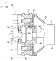
図1は、本発明の第1実施形態を示す。第1実施形態は、フォークリフト等の車両、建設機械等の動力源としてのハイブリッドパワーユニット10に本発明を適用した例を示す。ハイブリッドパワーユニット10は、エンジン20とモータ30を併用しており、モータ30は発電機としても機能する。各図中、矢印によりハイブリッドパワーユニット10の各方向を示している。以下の説明において、方向に関する記述は、この方向を基準として行うものとする。
FIG. 1 shows a first embodiment of the present invention. 1st Embodiment shows the example which applied this invention to the
図1には、ハイブリッドパワーユニット10がモータ30を中心に記載されており、モータ30のX方向にはエンジン20が配置され、モータ30の反X方向にはオイルポンプ40が配置されている。モータ30の回転軸35は、エンジン20のクランク軸22に結合され、また、モータ30の回転軸35は、結合部材44を介してオイルポンプ40のポンプ軸42に結合されている。エンジン20のクランク軸22は、エンジン20のシリンダブロック21に設けられた軸受20a(図7参照))により回転自在に支持されている。また、オイルポンプ40のポンプ軸42は、オイルポンプ40のポンプ本体41に設けられた軸受(不図示)により回転自在に支持されている。しかし、モータ30は軸受レス構造とされている。そのため、モータ30の回転軸35のX方向(エンジン20側)端面には、エンジン20のクランク軸22の反X方向(モータ30側)端部22aを受け入れるように窪まされた穴35aが形成されている。そして、この穴35aにクランク軸22のモータ側端部22aが嵌め込まれて固定されている。この場合の穴35aは、回転軸35の全体を貫通する孔の一部によって形成されている。但し、穴35aは、クランク軸22のモータ側端部22aを受け入れるだけの大きさの有底穴とされてもよい。
In FIG. 1, the
モータ30は、ブラシレスモータであり、ハウジング31の内周側に固定子32が設けられ、回転軸35の外周側に回転子33が設けられている。回転子33は、固定子32の内周側に位置して、固定子32の巻線(不図示)に電流を供給されることにより回転子33が回転駆動されて電動機として機能する。また、回転子33がクランク軸22又はポンプ軸42により回転駆動されることにより固定子32の巻線から電流が取り出されて発電機として機能する。
The
モータ30の反X方向(オイルポンプ40側)端部には、モータ30内部を閉鎖するための隔壁37が設けられている。隔壁37は、モータ30の外形に沿って環状に形成され、隔壁37の中心部は、結合部材44により閉鎖されている。隔壁37は、モータ30のハウジング31に固定され、結合部材44はモータ30の回転軸35の反X方向(オイルポンプ40側)端部に固定されている。
A
オイルポンプ40のポンプ本体41は、傘形状のポンプ支持部材43により隔壁37を挟んでモータ30のハウジング31の外周部に固定されている。また、結合部材44は、ポンプ軸42のX方向(モータ30側)端部に固定され、モータ30の回転軸35の反X方向(オイルポンプ40側)端部に固定されている。この回転軸35に対する結合部材44の固定はボルト45により行われている。図1ではボルト45を一つのみ図示したが、このボルト45による固定は、回転軸35の反X方向(オイルポンプ40側)端部の円環形状に沿って複数箇所で行われている。
The
モータ30のX方向(エンジン20側)には、モータ30、エンジン20間の境界を成し、モータ30の外側容器であるエンドプレート36を備える。従って、エンドプレート36は、モータ30のハウジング31の外周側に一体に結合されている。エンドプレート36の反X方向(モータ30側)壁面には、回転センサ50の固定子51が固定されている。また、モータ30の回転軸35上で回転センサ50の固定子51に対向する位置には、固定子51と共に回転センサ50を成す回転子52が固定されている。
In the X direction of the motor 30 (on the
図4は、回転センサ50を拡大して示す。回転センサ50の固定子51は、薄板の電磁鋼板を積層した構造の鉄心51aが全体として円形リング形に形成され、その内周側に巻線を巻いて構成された巻線部51bが周方向に複数個形成されている。回転センサ50の回転子52は、固定子51の巻線部51bの内周側に微小ギャップを介して配置されている。回転子52は、固定子51と同様、円形リング形に形成され、固定子51の巻線部51bに対向して、外周側に複数の突部52aが形成されている。
FIG. 4 shows the
巻線部51bには、図示を省略したが、2種類の巻線が層を成して巻かれている。一つは固定子51の巻線部51bの鉄心51aを励磁するための励磁巻線であり、他の一つは鉄心51aの磁束密度の変化を検出する検出巻線である。巻線部51bの励磁巻線に電流が流されると、鉄心51aが励磁される。そして、回転子52がモータ30の回転軸35により回転されて固定子51の内周側で突部52aが周方向に移動すると、巻線部51bの鉄心51aの磁束密度が、巻線部51bに対する突部52aの相対位置の変化に応じて変化する。その変化が巻線部51bの検出巻線により電圧変化として検出される。この検出信号は、端子箱51e内の端子(不図示)を介して出力信号線51fにより図示しないモータ30の制御回路に供給されて、モータ30の回転軸35の回転情報として取り込まれる。なお、巻線部51bの励磁巻線に流れる励磁電流は、励磁電流線51gによりモータ30の制御回路から供給される。
Although not shown in the drawing, the winding
固定子51の板面上には、板面を貫通し、且つ固定子51と同心の円弧状に形成された長孔51cが3個設けられている。3個の長孔51cは、固定子51の板面上に分散して配置されている。また、長孔51cの周方向の両側には、固定子51の板面を貫通し、固定子51の外周側が開放されて成る係合部51dが設けられている。
On the plate surface of the
図3、5に示すように、回転センサ50の固定子51は、エンドプレート36の中心で、モータ30側(反X方向)壁面に形成された凹部36dに嵌め込まれて固定されている。凹部36dは、固定子51の外形形状に対応する形状、大きさで窪まされて形成されている。また、固定子51のモータ30側(反X方向)面には、取付プレート53が当接されている。取付プレート53は、固定子51の鉄心51aにおける巻線部51bのない部分に対応する形状、大きさに形成されている。但し、取付プレート53は、鉄心51a上の端子箱51eと干渉しないように円形リング形の一部が切り欠かれている。取付プレート53には、固定子51の各長孔51cに対応して貫通孔(不図示)が形成されていると共に、その貫通孔の位置にナット53aが溶接固定されている。
As shown in FIGS. 3 and 5, the
一方、エンドプレート36には、固定子51の3個の長孔51cに対応して、エンドプレート36のエンジン20側からモータ30側まで貫通する3個のボルト挿通孔36aが穿設されている。各ボルト挿通孔36aには、それぞれボルト54が挿通され、それらのボルト54は、固定子51の各長孔51cを貫通して取付プレート53の各ナット53aに締結されている。
On the other hand, in the
具体的には、エンドプレート36の凹部36dに嵌め込まれた状態の固定子51及び取付プレート53に対して、各ボルト54を各ボルト挿通孔36aにエンジン20側から挿通する。このとき、各ボルト54は、固定子51の各長孔51cを貫通して取付プレート53の各ナット53aに締結される。このようにして、固定子51は、エンドプレート36に固定される。固定子51は、凹部36dに嵌め込まれることによりエンドプレート36の中心に半径方向の位置ずれなく固定される。しかし、固定子51の中心軸回りの回転角は、各長孔51cにより調整可能とされている。そのため、ボルト54による固定子51の締結力を弱くした状態で、固定子51の回転角度は調整される。
Specifically, each
エンドプレート36のボルト挿通孔36aの一つに隣接して、調整孔36bが設けられている。調整孔36bは、エンドプレート36を貫通する孔であり、エンドプレート36のX方向(エンジン20側)から固定子51の回転軸回りの回転角度を調整可能な位置に設けられている。具体的な調整の仕方は、針状の工具を調整孔36bから挿入し、工具の先端を固定子51の係合部51dに係合させて固定子51を中心軸回りに回転させることにより行う。係る調整時には、ボルト54の締結力を緩めるが、その操作はエンドプレート36のX方向(エンジン20側)から行う。そのため、ボルト54の締結力の調整と、調整孔36bを通じた固定子51の中心軸回りの回転操作とをエンドプレート36のX方向(エンジン20側)から同時に行うことができる。なお、図1では、ボルト54による固定子51の固定構造、及びその周辺の構造の記載が省略されている。
An
エンドプレート36のX方向(エンジン20側)面で、ボルト挿通孔36aよりもエンドプレート36の中心から離れた位置には貫通孔であるピン孔36cがY方向に分散して一対設けられている。一方、エンジン20におけるシリンダブロック21の反X方向(モータ30側)面上には、一対の基準ピン(不図示)が設けられている。この一対の基準ピンにエンドプレート36の一対のピン孔36cを嵌入させることにより、エンドプレート36がシリンダブロック21の基準位置に合わせて位置決めされる。
On the X direction (
図5に示すように、回転軸35のX方向(エンジン20側)端部には、軸径を細くして形成した段部35bが設けられ、この段部35bに回転センサ50の回転子52の内周側が嵌め込まれている。段部35bの回転子52のX方向(エンジン20側)には、押えリング55が焼き嵌めにて固定されている。押えリング55は、回転子52と同様の円板形状で、回転子52に対して、焼き嵌め後の内径が同一で、外径が小さくされている。このように回転軸35の外周上に固定された回転子52は、固定子51の内周側に対向して位置している。
As shown in FIG. 5, a
図7は、第1実施形態における回転センサ50の取付状態を模式的に示している。ここでは、エンジン20のクランク軸22は、X方向の両端に配置された一対の軸受20aにより軸支されている。一方、モータ30は軸受レス構造であり、その回転子33の回転軸35は、クランク軸22に結合されて片持ち支持されている。モータ30の回転センサ50は、その固定子51がモータ30の固定子32と一体のエンドプレート36に固定され、回転センサ50の回転子52がモータ30の回転軸35のX方向(エンジン20側)に固定されている。
FIG. 7 schematically shows the attachment state of the
図8は、第1実施形態による作用を示している。上述のように、モータ30が軸受レス構造とされていると、製造ばらつき等によりモータ30の回転子33及び回転軸35が芯ずれを起すことがある。芯ずれを起した状態では、クランク軸22の軸芯22bとモータ30の回転軸35の軸芯35cとが一つの直線上に重なった状態とならず、ずれた状態となる。このようにモータ30の回転軸35が芯ずれを起した場合、その影響で、回転センサ50の固定子51と回転子52との距離が周方向で均一とならず、回転センサ50の検出精度は低下する。しかし、モータ30の回転軸35が芯ずれを起したときの回転センサ50の固定子51と回転子52との距離の不均一は、仮想線で示すように、回転センサ50を反エンジン側に配置した場合に比べて、実線で示すように、回転センサ50をエンジン側に配置した場合の方が小さくなる。なお、図8においては、理解を容易にするため、芯ずれの程度を誇張して描いている。
FIG. 8 shows the operation according to the first embodiment. As described above, when the
このように第1実施形態によれば、モータ30の回転軸35が芯ずれを起したとしても、回転センサ50は芯ずれの影響を受けにくい状態とされる。その結果、モータ30の回転軸35の芯ずれに伴う回転センサ50の検出精度の低下を抑制することができる。
As described above, according to the first embodiment, even if the
また、回転センサ50の固定子51は、エンドプレート36の凹部36dに嵌め込まれて固定される。そのため、固定子51は、回転角を変更可能とされているが、その他の方向への移動はできず、凹部36dによって決められた位置に精度良く固定することができる。更に、モータ30の回転軸35のX方向(エンジン20側)端部は、クランク軸22の反X方向(モータ30側)端部を穴35a内に受け入れて嵌合結合されている。そのため、モータ30の回転軸35上に固定される回転センサ50の回転子52は、クランク軸22上に固定されているのと同等となる。従って、モータ30の回転軸35の芯ずれに伴う回転センサ50の検出精度の低下を抑制することができる。
In addition, the
図6は、本発明の第2実施形態を示す。第2実施形態が第1実施形態に対して特徴とする点は、第1実施形態では、回転センサ50の固定子51の内周側に回転子52を配置する構成としたのに対し、第2実施形態では、回転センサ50Aの固定子51Aの外周側に回転子52Aを配置する構成とした点である。その他の点は両者同一であり、同一部分の再度の説明は省略する。
FIG. 6 shows a second embodiment of the present invention. The feature of the second embodiment over the first embodiment is that, in the first embodiment, the
第2実施形態の場合、回転センサ50Aの固定子51Aは、その外周側に巻線部を備え、固定子51Aの内周側においてエンドプレート36に固定されている。また、回転子52Aは、回転軸35の外周側に延びるフランジ部34の先端内周側に固定されている。固定子51Aのエンドプレート36に対する固定の仕方、並びに回転子52Aのフランジ部34に対する固定の仕方は、第1実施形態の場合における固定子51のエンドプレート36に対する固定の仕方、並びに回転子52の回転軸35に対する固定の仕方と同一である。
In the case of the second embodiment, the
第2実施形態においても、回転センサ50Aの固定子51Aは、モータ30のエンドプレート36に固定され、回転センサ50Aの回転子52Aは、モータ30の内部で、固定子51Aに対向してエンジン20に近い側に固定される。そのため、軸受20aで支持された状態のクランク軸22から離れた側に回転センサ50Aが固定された場合に比べて、モータ30の回転軸35が芯ずれを起したとしても、回転センサ50Aは芯ずれの影響を受けにくい状態とされる。その結果、モータ30の回転軸35の芯ずれに伴う回転センサ50Aの検出精度の低下を抑制することができる。
Also in the second embodiment, the
以上、特定の実施形態について説明したが、本発明は、それらの外観、構成に限定されず、本発明の要旨を変更しない範囲で種々の変更、追加、削除が可能である。例えば、上記各実施形態では、エンジンのクランク軸及びモータの回転軸にはオイルポンプが接続され、ハイブリッドパワーユニットの出力を油圧に変換するものとしたが、ハイブリッドパワーユニットの出力を直接動力として利用するものとしてもよい。また、上記各実施形態では、ハイブリッドパワーユニットをフォークリフト、建設機械等の車両の動力源として使用するものとしたが、乗用車等の一般車両の動力源として使用するものとしてもよい。 As mentioned above, although specific embodiment was described, this invention is not limited to those external appearances and structures, A various change, addition, and deletion are possible in the range which does not change the summary of this invention. For example, in each of the above embodiments, an oil pump is connected to the crankshaft of the engine and the rotating shaft of the motor, and the output of the hybrid power unit is converted to hydraulic pressure. However, the output of the hybrid power unit is directly used as power. It is good. In each of the above embodiments, the hybrid power unit is used as a power source for vehicles such as forklifts and construction machines, but may be used as a power source for general vehicles such as passenger cars.
10 ハイブリッドパワーユニット
20 エンジン
20a 軸受
21 シリンダブロック
22 クランク軸
22a モータ側端部
22b 軸芯
30 モータ
31 ハウジング
32 固定子
33 回転子
34 フランジ部
35 回転軸
35a 穴
35b 段部
35c 軸芯
36 エンドプレート
36a ボルト挿通孔
36b 調整孔
36c ピン孔
36d 凹部
37 隔壁
40 オイルポンプ
41 ポンプ本体
42 ポンプ軸
43 ポンプ支持部材
44 結合部材
45 ボルト
50、50A 回転センサ
51、51A 固定子
51a 鉄心
51b 巻線部
51c 長孔
51d 係合部
51e 端子箱
51f 出力信号線
51g 励磁電流線
52、52A 回転子
52a 突部
53 取付プレート
53a ナット
54 ボルト
55 押えリング
DESCRIPTION OF
Claims (2)
モータ、エンジン間の境界を成し、モータの外側容器としてモータのハウジングと一体に結合されたエンドプレートと、
該エンドプレートのモータ側壁面に固定され、モータの回転軸の外周に沿って環状に形成された回転センサの固定子と、
モータの回転軸上で前記回転センサの固定子に対向して固定され、前記固定子と共に回転センサを成す回転子とを備え、
前記エンドプレートのモータ側壁面に配置された前記固定子のモータ側面に当接される取付プレートと、
前記エンドプレート及び前記固定子を貫通した状態で、前記エンドプレートのエンジン側から挿入されており、前記固定子を挟んで前記取付プレートを前記エンドプレートに固定するボルトとを備え、
前記エンドプレートの前記固定子に対応する位置であり、且つ前記エンドプレートのエンジン側から前記固定子における前記回転軸回りの回転角度を調整可能な位置には、前記エンドプレートを貫通する調整孔が形成されており、
前記エンドプレートのモータ側壁面には、前記回転センサの固定子の外形形状に対応して環状に窪まされた凹部が形成されており、この凹部に前記回転センサの固定子が嵌め込まれて固定されており、
モータの回転軸のエンジン側端面には、エンジンのクランク軸のモータ側端部を受け入れるように窪まされた穴が形成されており、この穴にクランク軸のモータ側端部が嵌め込まれて固定されており、
モータの回転軸の外周上には、前記回転センサの固定子の内周側に対応して前記回転センサの回転子が固定されているハイブリッドパワーユニット用モータの回転センサ取付構造。 In a hybrid power unit using both an engine and a motor, the rotation shaft is a motor rotation sensor mounting structure in which the rotation shaft is cantilevered by the engine crankshaft,
An end plate which forms a boundary between the motor and the engine and is integrally coupled to the motor housing as an outer container of the motor ;
A stator of a rotation sensor fixed to the motor side wall surface of the end plate and formed annularly along the outer periphery of the rotation shaft of the motor ;
A rotor which is fixed on the rotating shaft of the motor so as to face the stator of the rotation sensor and forms a rotation sensor together with the stator;
A mounting plate abutting on the motor side surface of the stator disposed on the motor side wall surface of the end plate;
In a state of passing through the end plate and the stator , it is inserted from the engine side of the end plate, and includes a bolt for fixing the mounting plate to the end plate across the stator,
An adjustment hole penetrating the end plate is located at a position corresponding to the stator of the end plate and at a position where the rotation angle of the stator around the rotation axis can be adjusted from the engine side of the end plate. Formed ,
On the motor side wall surface of the end plate, a recess is formed in an annular shape corresponding to the outer shape of the stator of the rotation sensor, and the stator of the rotation sensor is fitted and fixed in this recess. And
A hole that is recessed to receive the motor side end of the engine crankshaft is formed in the engine side end surface of the motor rotation shaft, and the motor side end of the crankshaft is fitted and fixed in this hole. And
A rotation sensor mounting structure for a motor for a hybrid power unit , wherein the rotor of the rotation sensor is fixed on the outer periphery of the rotation shaft of the motor corresponding to the inner periphery of the stator of the rotation sensor.
モータの回転軸には、該回転軸の外周側に延びるフランジ部が設けられており、
該フランジ部の先端内周側には、前記回転センサの固定子の外周側に対向して前記回転センサの回転子が固定されているハイブリッドパワーユニット用モータの回転センサ取付構造。
In claim 1,
The rotating shaft of the motor is provided with a flange portion extending to the outer peripheral side of the rotating shaft,
A rotation sensor mounting structure for a motor for a hybrid power unit, wherein the rotor of the rotation sensor is fixed to the inner peripheral side of the front end of the flange portion so as to face the outer periphery of the stator of the rotation sensor.
Priority Applications (2)
| Application Number | Priority Date | Filing Date | Title |
|---|---|---|---|
| JP2016069986A JP6428696B2 (en) | 2016-03-31 | 2016-03-31 | Rotation sensor mounting structure for hybrid power unit motor |
| EP17163276.3A EP3225447B1 (en) | 2016-03-31 | 2017-03-28 | Hybrid power unit |
Applications Claiming Priority (1)
| Application Number | Priority Date | Filing Date | Title |
|---|---|---|---|
| JP2016069986A JP6428696B2 (en) | 2016-03-31 | 2016-03-31 | Rotation sensor mounting structure for hybrid power unit motor |
Publications (3)
| Publication Number | Publication Date |
|---|---|
| JP2017184507A JP2017184507A (en) | 2017-10-05 |
| JP2017184507A5 JP2017184507A5 (en) | 2018-01-25 |
| JP6428696B2 true JP6428696B2 (en) | 2018-11-28 |
Family
ID=58454902
Family Applications (1)
| Application Number | Title | Priority Date | Filing Date |
|---|---|---|---|
| JP2016069986A Active JP6428696B2 (en) | 2016-03-31 | 2016-03-31 | Rotation sensor mounting structure for hybrid power unit motor |
Country Status (2)
| Country | Link |
|---|---|
| EP (1) | EP3225447B1 (en) |
| JP (1) | JP6428696B2 (en) |
Cited By (1)
| Publication number | Priority date | Publication date | Assignee | Title |
|---|---|---|---|---|
| US20220001853A1 (en) * | 2020-07-01 | 2022-01-06 | Mazda Motor Corporation | Vehicle |
Families Citing this family (4)
| Publication number | Priority date | Publication date | Assignee | Title |
|---|---|---|---|---|
| CN110071605B (en) * | 2018-01-23 | 2020-12-22 | 赛卓电子科技(上海)有限公司 | Motor mounting structure with electromagnetic induction type rotary transformer |
| JP2020124015A (en) * | 2019-01-29 | 2020-08-13 | 本田技研工業株式会社 | Rotary electric machine unit and resolver stator |
| CN110571976A (en) * | 2019-09-18 | 2019-12-13 | 精进电动科技股份有限公司 | Engine and motor assembly |
| ES2798048B2 (en) * | 2020-10-01 | 2021-08-05 | Univ Madrid Politecnica | ROTARY SENSOR FOR MEASURING ALTERNATING CURRENT AND / OR DIRECT CURRENT IN ROTATING MACHINES |
Family Cites Families (12)
| Publication number | Priority date | Publication date | Assignee | Title |
|---|---|---|---|---|
| JP2000224797A (en) * | 1999-01-29 | 2000-08-11 | Mitsubishi Automob Eng Co Ltd | Motor supporting structure |
| JP3591354B2 (en) * | 1999-01-29 | 2004-11-17 | 三菱自動車エンジニアリング株式会社 | Motor support structure |
| JP2005057832A (en) * | 2003-08-05 | 2005-03-03 | Honda Motor Co Ltd | Electric motor and hybrid vehicle having same |
| JP2005080430A (en) * | 2003-09-01 | 2005-03-24 | Tamagawa Seiki Co Ltd | Motor with built-in resolver |
| WO2005105507A1 (en) | 2004-04-28 | 2005-11-10 | Aisin Aw Co., Ltd | Drive device for hybrid vehicle |
| JP4297918B2 (en) * | 2006-03-23 | 2009-07-15 | トヨタ自動車株式会社 | Power transmission device and assembly method thereof |
| JP2007336714A (en) * | 2006-06-15 | 2007-12-27 | Toyota Motor Corp | Fixing structure of resolver sensor |
| JP2008145153A (en) * | 2006-12-07 | 2008-06-26 | Toyota Motor Corp | Rotating electrical machine |
| JP2008143439A (en) * | 2006-12-13 | 2008-06-26 | Mitsuba Corp | Hybrid car |
| GB201117931D0 (en) * | 2011-10-18 | 2011-11-30 | Cummins Generator Technologies | Housing arrangement for an electrical machine |
| US9421854B2 (en) * | 2012-01-20 | 2016-08-23 | Toyota Jidosha Kabushiki Kaisha | Vehicle drive device |
| JP5728458B2 (en) * | 2012-11-05 | 2015-06-03 | 本田技研工業株式会社 | Drive unit with rotation detector |
-
2016
- 2016-03-31 JP JP2016069986A patent/JP6428696B2/en active Active
-
2017
- 2017-03-28 EP EP17163276.3A patent/EP3225447B1/en active Active
Cited By (2)
| Publication number | Priority date | Publication date | Assignee | Title |
|---|---|---|---|---|
| US20220001853A1 (en) * | 2020-07-01 | 2022-01-06 | Mazda Motor Corporation | Vehicle |
| US11608052B2 (en) * | 2020-07-01 | 2023-03-21 | Mazda Motor Corporation | Vehicle |
Also Published As
| Publication number | Publication date |
|---|---|
| EP3225447B1 (en) | 2018-09-26 |
| JP2017184507A (en) | 2017-10-05 |
| EP3225447A1 (en) | 2017-10-04 |
Similar Documents
| Publication | Publication Date | Title |
|---|---|---|
| JP6428696B2 (en) | Rotation sensor mounting structure for hybrid power unit motor | |
| JP5786642B2 (en) | Stator fixing structure | |
| JP5718391B2 (en) | Rotating electric machine | |
| US6624545B1 (en) | Electric rotating machine and manufacturing method thereof | |
| US8987954B2 (en) | On-vehicle motor including detector for detecting state of motor | |
| JP5631133B2 (en) | Fixing method of metal pipe to rotor core in rotor for rotary electric machine | |
| US10666103B2 (en) | Rotor of rotating electric machine | |
| JP5728704B2 (en) | Resolver mounting structure | |
| JP5803567B2 (en) | Stator fixing structure | |
| JP2009050055A (en) | Rotor of rotary electric machine | |
| JP2012228024A (en) | Resolver | |
| CN106464044A (en) | Switched reluctance motor | |
| JP2007195281A (en) | Stator core for dynamo-electric machine, and stator using that stator core | |
| JP4622897B2 (en) | Rotating electric machine stator | |
| JP5643038B2 (en) | Rotor for rotating electrical machines | |
| JP5696642B2 (en) | Stator fixing structure | |
| JP5937458B2 (en) | Stator, outer rotor type rotating electrical machine using the stator, and stator manufacturing method | |
| JP2008199856A (en) | Stator core, rotary electric machine and rotary electric machine unit | |
| JP6659169B2 (en) | Rotor and rotating electric machine | |
| JP2017184506A (en) | Dustproof construction of motor for hybrid power unit | |
| KR20190060827A (en) | Rotary electric armature, rotary electric machine, hoisting machine for elevator and manufacturing method of armature | |
| JP5772393B2 (en) | Rotating electrical machine cooling structure and manufacturing method thereof | |
| JP6945955B2 (en) | Angle detector and manufacturing method of angle detector | |
| JP6855307B2 (en) | Drive device | |
| US11063483B2 (en) | Electric motor |
Legal Events
| Date | Code | Title | Description |
|---|---|---|---|
| A621 | Written request for application examination |
Free format text: JAPANESE INTERMEDIATE CODE: A621 Effective date: 20170711 |
|
| A521 | Written amendment |
Free format text: JAPANESE INTERMEDIATE CODE: A523 Effective date: 20171208 |
|
| A131 | Notification of reasons for refusal |
Free format text: JAPANESE INTERMEDIATE CODE: A131 Effective date: 20180424 |
|
| A977 | Report on retrieval |
Free format text: JAPANESE INTERMEDIATE CODE: A971007 Effective date: 20180427 |
|
| A521 | Written amendment |
Free format text: JAPANESE INTERMEDIATE CODE: A523 Effective date: 20180619 |
|
| TRDD | Decision of grant or rejection written | ||
| A01 | Written decision to grant a patent or to grant a registration (utility model) |
Free format text: JAPANESE INTERMEDIATE CODE: A01 Effective date: 20181002 |
|
| A61 | First payment of annual fees (during grant procedure) |
Free format text: JAPANESE INTERMEDIATE CODE: A61 Effective date: 20181015 |
|
| R151 | Written notification of patent or utility model registration |
Ref document number: 6428696 Country of ref document: JP Free format text: JAPANESE INTERMEDIATE CODE: R151 |