JP6426191B2 - Expansion turbine and turbocharger - Google Patents
Expansion turbine and turbocharger Download PDFInfo
- Publication number
- JP6426191B2 JP6426191B2 JP2016545164A JP2016545164A JP6426191B2 JP 6426191 B2 JP6426191 B2 JP 6426191B2 JP 2016545164 A JP2016545164 A JP 2016545164A JP 2016545164 A JP2016545164 A JP 2016545164A JP 6426191 B2 JP6426191 B2 JP 6426191B2
- Authority
- JP
- Japan
- Prior art keywords
- turbine
- expansion turbine
- wall surface
- moving blade
- working fluid
- Prior art date
- Legal status (The legal status is an assumption and is not a legal conclusion. Google has not performed a legal analysis and makes no representation as to the accuracy of the status listed.)
- Active
Links
Images


Classifications
-
- F—MECHANICAL ENGINEERING; LIGHTING; HEATING; WEAPONS; BLASTING
- F01—MACHINES OR ENGINES IN GENERAL; ENGINE PLANTS IN GENERAL; STEAM ENGINES
- F01D—NON-POSITIVE DISPLACEMENT MACHINES OR ENGINES, e.g. STEAM TURBINES
- F01D9/00—Stators
- F01D9/02—Nozzles; Nozzle boxes; Stator blades; Guide conduits, e.g. individual nozzles
- F01D9/026—Scrolls for radial machines or engines
-
- F—MECHANICAL ENGINEERING; LIGHTING; HEATING; WEAPONS; BLASTING
- F02—COMBUSTION ENGINES; HOT-GAS OR COMBUSTION-PRODUCT ENGINE PLANTS
- F02B—INTERNAL-COMBUSTION PISTON ENGINES; COMBUSTION ENGINES IN GENERAL
- F02B37/00—Engines characterised by provision of pumps driven at least for part of the time by exhaust
-
- F—MECHANICAL ENGINEERING; LIGHTING; HEATING; WEAPONS; BLASTING
- F01—MACHINES OR ENGINES IN GENERAL; ENGINE PLANTS IN GENERAL; STEAM ENGINES
- F01D—NON-POSITIVE DISPLACEMENT MACHINES OR ENGINES, e.g. STEAM TURBINES
- F01D25/00—Component parts, details, or accessories, not provided for in, or of interest apart from, other groups
- F01D25/24—Casings; Casing parts, e.g. diaphragms, casing fastenings
-
- F—MECHANICAL ENGINEERING; LIGHTING; HEATING; WEAPONS; BLASTING
- F02—COMBUSTION ENGINES; HOT-GAS OR COMBUSTION-PRODUCT ENGINE PLANTS
- F02B—INTERNAL-COMBUSTION PISTON ENGINES; COMBUSTION ENGINES IN GENERAL
- F02B39/00—Component parts, details, or accessories relating to, driven charging or scavenging pumps, not provided for in groups F02B33/00 - F02B37/00
-
- F—MECHANICAL ENGINEERING; LIGHTING; HEATING; WEAPONS; BLASTING
- F04—POSITIVE - DISPLACEMENT MACHINES FOR LIQUIDS; PUMPS FOR LIQUIDS OR ELASTIC FLUIDS
- F04D—NON-POSITIVE-DISPLACEMENT PUMPS
- F04D25/00—Pumping installations or systems
- F04D25/02—Units comprising pumps and their driving means
- F04D25/04—Units comprising pumps and their driving means the pump being fluid-driven
-
- F—MECHANICAL ENGINEERING; LIGHTING; HEATING; WEAPONS; BLASTING
- F05—INDEXING SCHEMES RELATING TO ENGINES OR PUMPS IN VARIOUS SUBCLASSES OF CLASSES F01-F04
- F05D—INDEXING SCHEME FOR ASPECTS RELATING TO NON-POSITIVE-DISPLACEMENT MACHINES OR ENGINES, GAS-TURBINES OR JET-PROPULSION PLANTS
- F05D2240/00—Components
- F05D2240/10—Stators
- F05D2240/12—Fluid guiding means, e.g. vanes
-
- Y—GENERAL TAGGING OF NEW TECHNOLOGICAL DEVELOPMENTS; GENERAL TAGGING OF CROSS-SECTIONAL TECHNOLOGIES SPANNING OVER SEVERAL SECTIONS OF THE IPC; TECHNICAL SUBJECTS COVERED BY FORMER USPC CROSS-REFERENCE ART COLLECTIONS [XRACs] AND DIGESTS
- Y02—TECHNOLOGIES OR APPLICATIONS FOR MITIGATION OR ADAPTATION AGAINST CLIMATE CHANGE
- Y02T—CLIMATE CHANGE MITIGATION TECHNOLOGIES RELATED TO TRANSPORTATION
- Y02T10/00—Road transport of goods or passengers
- Y02T10/10—Internal combustion engine [ICE] based vehicles
- Y02T10/12—Improving ICE efficiencies
Description
本開示は、可変ノズルを有する膨張タービン及び該膨張タービンを備えたターボチャージャに関する。 The present disclosure relates to an expansion turbine having a variable nozzle and a turbocharger provided with the expansion turbine.
近年、燃費向上を狙って自動車用内燃機関にターボチャージャを装着する傾向が顕著である。ターボチャージャの中で、膨張タービンの入口側に可変ノズルを有する可変容量ターボチャージャがあり、可変容量ターボチャージャは可変ノズルの開度調整で作動流体の流量調整が可能になる。そのため、内燃機関の負荷変動に合わせた運転が可能になると共に、特に、低負荷時のレスポンス性能に優れている。
しかし、可変容量ターボチャージャの特性として、図8に示すように、可変ノズルの開度が小さいとき、タービン効率は、ピーク点(ノズル開度が中開度域付近)と比べて大きく低下する。ノズル開度が小開度域のときのタービン効率は、レスポンス性能に大きく影響する。このため、小開度域でタービン効率を向上させることが求められている。In recent years, there has been a marked tendency to attach a turbocharger to an internal combustion engine for a vehicle in order to improve fuel consumption. Among the turbochargers, there is a variable displacement turbocharger having a variable nozzle on the inlet side of the expansion turbine, and the variable displacement turbocharger can adjust the flow rate of the working fluid by adjusting the opening of the variable nozzle. As a result, it becomes possible to operate according to the load fluctuation of the internal combustion engine, and in particular, it is excellent in the response performance at low load.
However, as a characteristic of the variable capacity turbocharger, as shown in FIG. 8, when the opening degree of the variable nozzle is small, the turbine efficiency is greatly reduced compared to the peak point (the nozzle opening is near the middle opening area). The turbine efficiency when the nozzle opening is in the small opening region greatly affects the response performance. Therefore, there is a need to improve turbine efficiency in a small opening range.
小開度域でのタービン効率を向上させるためには、可変ノズルのインシデンス角(可変ノズルへ流入する作動流体の流入角と可変ノズルの前縁翼角度との差)を小さくすることが有利である。そこで、インシデンス角を小さくするため、小開度域における可変ノズルの前縁翼角度に応じて、タービンハウジングのスクロール部を絞る(スクロール部を小さくする)ことが考えられる。
一方、スクロール部を絞ると、ノズル開度が大開度域のときのインシデンス角が大きくなり、可変ノズルの翼面で流れの剥離が生じ、実流路面積が低下し、作動流体の流量(最大流量)が低下してしまうという問題がある。
このように、タービンハウジングのスクロール部の形状の工夫だけで、可変ノズルの小開度域におけるタービン効率向上と、可変ノズルの大開度域における最大流量の確保と、を両立することは容易ではない。そこで、スクロール部の形状変更以外の手法も活用することで、これら二つの要求を満たすことが望まれる。In order to improve turbine efficiency in the small opening region, it is advantageous to reduce the incidence angle of the variable nozzle (the difference between the inflow angle of the working fluid flowing into the variable nozzle and the leading edge blade angle of the variable nozzle). is there. Therefore, in order to reduce the incidence angle, it is conceivable to narrow the scroll portion of the turbine housing (make the scroll portion smaller) in accordance with the leading edge blade angle of the variable nozzle in the small opening range.
On the other hand, when the scroll portion is narrowed, the incidence angle increases when the nozzle opening is in the large opening range, flow separation occurs on the wing surface of the variable nozzle, the actual flow area decreases, and the working fluid flow rate (maximum There is a problem that the flow rate) decreases.
Thus, it is not easy to simultaneously improve the turbine efficiency improvement in the small opening area of the variable nozzle and secure the maximum flow rate in the large opening area of the variable nozzle only by devising the shape of the scroll portion of the turbine housing . Therefore, it is desirable that these two requirements be satisfied by utilizing methods other than the shape change of the scroll portion.
なお、可変ノズルの小開度域におけるタービン効率向上と大開度域における最大流量の確保の両立を図ったものではないが、特許文献1には、動翼のチップに対向するタービンハウジングのシュラウド壁面における動翼の入口側に、タービンの半径方向に対してタービンホイールの背面側に向かって傾斜した環状のガイド部(ガイド面)が形成されたタービンが開示されている。
特許文献1に記載のタービンでは、前記ガイド部の形成により、動翼に流入した作動流体をタービンホイールの背面側へ寄せ、可変ノズルの後流(ウェイク)による励振力が動翼先端縁付近に作用することを抑制し、動翼の振れが抑制される。また、前記ガイド部によって動翼とシュラウド壁面との間の隙間を塞ぐことで、該隙間を介したクリアランスフローが抑制されるようになっている。Although it is not intended to simultaneously improve the turbine efficiency in the small opening area of the variable nozzle and ensure the maximum flow rate in the large opening area,
In the turbine described in
しかしながら、特許文献1に開示されたタービンでは、動翼とシュラウド壁面との間の隙間を介したクリアランスフローを低減するために、前記ガイド部をハブ側に大きく突出させている。このため、動翼入口前縁の一部はガイド部の先端によって覆われており、流路幅が最も狭まる箇所が動翼入口の上流側に存在する。したがって、縮流効果によって動翼前縁の一部には作動流体が流れ込まず、所期の動翼性能を発揮できず、タービン効率が低下するおそれがある。 However, in the turbine disclosed in
本発明の少なくとも一実施形態は、かかる従来技術の課題に鑑み、可変ノズルが小開度域のときのタービン効率の低下を抑制すると共に、可変ノズルが大開度域のときの作動流体の流量を確保し、併せて、所期の動翼性能を引き出してタービン効率の低下を抑制することができる膨張タービン及びターボチャージャを提供することを目的とする。 In view of the problems of the related art, at least one embodiment of the present invention suppresses the decrease in turbine efficiency when the variable nozzle is in the small opening range, and at the same time, the flow rate of the working fluid when the variable nozzle is in the large opening range. It is an object of the present invention to provide an expansion turbine and a turbocharger capable of securing and simultaneously achieving desired blade performance and suppressing reduction in turbine efficiency.
(1)本発明の少なくとも一実施形態に係る膨張タービンは、作動流体が持つエネルギーから動力を回収するための膨張タービンであって、前記作動流体が導入されるスクロール部を含むタービンハウジングと、前記タービンハウジング内において前記膨張タービンの周方向に間隔を空けて配置され、前記スクロール部を通過した前記作動流体の流路面積が変化するように回動軸周りに回動可能に構成された複数の可変ノズルと、前記可変ノズルの下流側に位置する動翼を複数有し、前記タービンハウジング内に回転自在に設けられたタービンホイールと、を備え、
前記タービンハウジングは、前記動翼のチップに対向するシュラウド部を含む第1壁面と、前記作動流体の流路を挟んで前記第1壁面に対向する第2壁面とを有し、
前記可変ノズルの出口側の翼高さは前記動翼の入口側の翼高さより大きく、
前記シュラウド部は、前記可変ノズルの出口の下流側かつ前記動翼の入口の上流側において、前記作動流体の流路高さが下流側に向かって狭まるように、前記第2壁面に向かって突出する突出部を有し、
前記突出部の突出量は、前記突出部の先端が前記動翼の前記入口の前記チップを越えて前記第2壁面側に突出しないように設定されている。(1) An expansion turbine according to at least one embodiment of the present invention is an expansion turbine for recovering power from energy possessed by a working fluid, the turbine housing including a scroll portion into which the working fluid is introduced; A plurality of circumferentially spaced-apart circumferential directions of the expansion turbine in the turbine housing, and configured to be rotatable about a rotation axis so as to change a flow passage area of the working fluid passing through the scroll portion. A variable nozzle, and a plurality of moving blades located downstream of the variable nozzle, and a turbine wheel rotatably provided in the turbine housing,
The turbine housing has a first wall surface including a shroud portion facing the tip of the moving blade, and a second wall surface facing the first wall surface across the flow path of the working fluid,
The blade height on the outlet side of the variable nozzle is greater than the blade height on the inlet side of the moving blade,
The shroud portion protrudes toward the second wall surface so that the flow channel height of the working fluid narrows toward the downstream side on the downstream side of the outlet of the variable nozzle and on the upstream side of the inlet of the moving blade Have projecting parts,
The protrusion amount of the protrusion is set such that the tip end of the protrusion does not protrude beyond the tip at the inlet of the moving blade to the second wall surface side.
前記構成(1)によれば、可変ノズルの出口側の翼高さを動翼の入口側の翼高さより大きくしたことで、可変ノズル間の作動流体流路におけるスロート面積を増大させることができる。よって、可変ノズルが大開度域のとき動翼に流入する作動流体の流量(最大流量)を十分に確保できる。 According to the above configuration (1), by setting the blade height on the outlet side of the variable nozzle to be larger than the blade height on the inlet side of the moving blade, the throat area in the working fluid flow path between the variable nozzles can be increased. . Therefore, when the variable nozzle is in the wide opening range, the flow rate (maximum flow rate) of the working fluid flowing into the moving blades can be sufficiently secured.
また、可変ノズルが小開度域のとき、動翼に流れ込む作動流体は、ノズル開度が小さいために強い旋回成分を持つ一方、半径方向内側に向かう流速成分は小さい。そのため、従来の膨張タービンでは、可変ノズルの小開度域において、動翼に流入する作動流体が持つ旋回成分に起因した遠心力により、作動流体はシュラウド側(第1壁面側)に押し付けられやすい。作動流体がシュラウド壁面側に押し付けられると、動翼出口において、作動流体の流れはシュラウド側に偏り、シュラウド側で流速が大きく、ハブ側(第2壁面側)で流速が小さくなる。そのため、動翼の下流側で流速不均衡を解消するように作動流体が広がり、混合損失が起こりやすい。
この点、前記構成(1)によれば、前記突出部を有するので、作動流体は突出部に沿って流れることで第2壁面側(ハブ側)へ寄せられ、第1壁面側(シュラウド側)への作動流体の偏流が抑制される。そのため、動翼出口での不均衡な流れが緩和され、混合損失が低減するため、タービン効率が向上する。
従って、前記構成(1)により、上述した可変ノズルの大開度域における最大流量確保というメリットに加えて、可変ノズルが小開度域のときのタービン効率向上というメリットも享受できる。Further, when the variable nozzle is in the small opening range, the working fluid flowing into the moving blade has a strong swirling component because the nozzle opening is small, while the flow velocity component directed inward in the radial direction is small. Therefore, in the conventional expansion turbine, in the small opening degree region of the variable nozzle, the working fluid is easily pressed to the shroud side (the first wall side) by the centrifugal force caused by the turning component of the working fluid flowing into the moving blade. . When the working fluid is pressed to the shroud wall surface side, the flow of the working fluid is biased to the shroud side at the blade outlet, the flow velocity is large on the shroud side, and the flow velocity is reduced on the hub side (second wall surface). Therefore, the working fluid spreads so as to eliminate the flow velocity imbalance on the downstream side of the moving blade, and mixing loss is likely to occur.
In this respect, according to the configuration (1), since the projecting portion is provided, the working fluid flows along the projecting portion so as to be brought closer to the second wall side (hub side), and the first wall side (shroud side) The partial flow of the working fluid is suppressed. As a result, uneven flow at the blade exit is alleviated, and mixing loss is reduced, thereby improving turbine efficiency.
Therefore, in addition to the merit of securing the maximum flow rate in the wide opening range of the variable nozzle described above, the configuration (1) can also enjoy the merit of improving the turbine efficiency when the variable nozzle is in the small opening range.
また、前記構成(1)によれば、前記突出部の突出量は、前記突出部の先端が動翼の入口のチップを越えて第2壁面側に突出しないように設定されているので、動翼高さ方向における広い範囲に作動流体が流れ込むので、突出部による縮流効果に起因した動翼入口における実効流路面積の低下を抑制できる。そのため、所期の動翼性能が得られやすくなり、タービン効率を高く維持できる。 Further, according to the configuration (1), the protrusion amount of the protrusion is set so that the tip end of the protrusion does not protrude to the second wall side beyond the tip of the inlet of the moving blade. Since the working fluid flows into a wide range in the blade height direction, it is possible to suppress a reduction in the effective flow path area at the blade inlet due to the contraction effect by the protrusions. Therefore, desired blade performance can be easily obtained, and high turbine efficiency can be maintained.
(2)幾つかの実施形態では、前記構成(1)において、
前記膨張タービンは、前記膨張タービンの半径方向に沿って前記作動流体が前記動翼の前記入口に流れ込むラジアルタービンであり、
前記動翼の前記入口における根本の軸方向位置を原点とし、前記動翼の前記入口における前記チップの軸方向位置をXtとしたとき、前記突出部の先端の軸方向位置Xpは0<Xt≦Xpの関係を満たしている。
前記構成(2)によれば、ラジアルタービンにおいて、前記突出部の突出量は、前記突出部の先端が動翼のハブ側に突出しないように設定されている。そのため、動翼入口における流路面積の低下を抑制できるので、所期の動翼性能が得られやすくなり、タービン効率を高く維持できる。(2) In some embodiments, in the configuration (1),
The expansion turbine is a radial turbine in which the working fluid flows into the inlet of the moving blade along a radial direction of the expansion turbine,
The origin of the axial position of the root of the inlet of the moving blade, when the axial position of the tip in the inlet of the moving blade and the X t, the axial position X p of the tip of the projecting portion is 0 < The relation of X t ≦ X p is satisfied.
According to the configuration (2), in the radial turbine, the amount of protrusion of the protrusion is set such that the tip end of the protrusion does not protrude toward the hub side of the moving blade. Therefore, since it is possible to suppress a decrease in the flow passage area at the blade inlet, desired blade performance can be easily obtained, and the turbine efficiency can be maintained high.
(3)幾つかの実施形態では、前記構成(2)において、
前記第1壁面は前記半径方向に対して傾斜したテーパ面を有し、該テーパ面によって前記突出部が形成されており、
前記テーパ面が前記膨張タービンの軸方向に対してなす角度が40度以下である。
前記構成(3)によれば、動翼入口の上流側において前記テーパ面に沿って作動流体を第2壁面側(ハブ側)へ十分に寄せることができ、そのため、第1壁面側(シュラウド側)への作動流体の偏流を抑制できる。これによって、動翼出口における流速分布を均一化し、混合損失を抑制することで、タービン効率が向上する。(3) In some embodiments, in the configuration (2),
The first wall surface has a tapered surface inclined with respect to the radial direction, and the projecting portion is formed by the tapered surface.
The angle formed by the tapered surface with respect to the axial direction of the expansion turbine is 40 degrees or less.
According to the configuration (3), the working fluid can be sufficiently moved to the second wall surface side (hub side) along the tapered surface on the upstream side of the moving blade inlet, and therefore the first wall surface side (shroud side It is possible to suppress the deviation of the working fluid to the By this, the flow velocity distribution at the blade exit is made uniform, and the mixing loss is suppressed, whereby the turbine efficiency is improved.
(4)幾つかの実施形態では、前記構成(2)又は(3)の何れかにおいて、
前記膨張タービンの中心軸から前記可変ノズルの前記回動軸までの前記半径方向における距離をRSとし、前記膨張タービンの中心軸から前記動翼の前記入口までの前記半径方向における距離をRRとしたとき、RS/RR≧1.4を満たす。
前記構成(4)によれば、可変ノズル出口から動翼入口までの距離が広がり、この部分の距離が広がることで、可変ノズル出口側で作動流体の流速低下が起り、静圧の低下を抑制できる。そのため、可変ノズルの圧力面と負圧面間の圧力差を低減できるので、クリアランスフローを抑制でき、タービン効率を向上できる。
特に、小開度域では、流れ損失全体に占めるクリアランスフローに起因した損失の割合が高いため、上記構成(4)による効果(クリアランスフローの抑制によるタービン効率向上効果)が大きい。(4) In some embodiments, in any of the above configurations (2) or (3),
The distance in the radial direction from the central axis of the expansion turbine to the pivot axis of the variable nozzle is R S, and the distance in the radial direction from the central axis of the expansion turbine to the inlet of the moving blade is R R R And R S / R R 1.41.4 is satisfied.
According to the above configuration (4), the distance from the variable nozzle outlet to the moving blade inlet increases, and the distance of this portion increases, so that the flow velocity of the working fluid decreases at the variable nozzle outlet side, suppressing the decrease in static pressure. it can. Therefore, since the pressure difference between the pressure surface and the suction surface of the variable nozzle can be reduced, the clearance flow can be suppressed, and the turbine efficiency can be improved.
In the small opening region, in particular, the ratio of loss due to the clearance flow to the entire flow loss is high, so the effect by the configuration (4) (effect of improving the turbine efficiency by suppressing the clearance flow) is large.
(5)幾つかの実施形態では、前記構成(1)〜(4)の何れかにおいて、
内燃機関からの排ガスによって駆動されるように構成された請求項1乃至6の何れか一項に記載の膨張タービンと、
前記膨張タービンによって駆動されて前記内燃機関への吸気を圧縮するように構成されたコンプレッサと、を備えたターボチャージャである。
前記構成(5)によれば、前記ターボチャージャにおいて、可変ノズルが小開度域のときのタービン効率の低下を抑制できると共に、可変ノズルが大開度域のときの作動流体の流量を確保することができる。また、所期の動翼性能が得られやすくなり、タービン効率を高く維持できる。(5) In some embodiments, in any of the above configurations (1) to (4),
The expansion turbine according to any one of
A compressor driven by the expansion turbine and configured to compress intake air to the internal combustion engine.
According to the configuration (5), in the turbocharger, it is possible to suppress a decrease in turbine efficiency when the variable nozzle is in the small opening range and secure a flow rate of the working fluid when the variable nozzle is in the large opening range. Can. In addition, desired blade performance can be easily obtained, and high turbine efficiency can be maintained.
本発明の少なくとも一実施形態によれば、可変ノズルが小開度域のときのタービン効率の低下を抑制すると共に、可変ノズルが大開度域のときの作動流体の流量を確保し、併せて、動翼性能の低下を抑制し、タービン効率の低下を抑制することができる。 According to at least one embodiment of the present invention, the decrease in turbine efficiency when the variable nozzle is in the small opening range is suppressed, and the flow rate of the working fluid when the variable nozzle is in the large opening range is secured. It is possible to suppress the decrease in blade performance and to suppress the decrease in turbine efficiency.
以下、添付図面を参照して本発明の幾つかの実施形態について説明する。ただし、実施形態として記載され又は図面に示されている構成部品の寸法、材質、形状、その相対的配置等は、本発明の範囲をこれに限定する趣旨ではなく、単なる説明例にすぎない。
例えば、「ある方向に」、「ある方向に沿って」、「平行」、「直交」、「中心」、「同心」或いは「同軸」等の相対的或いは絶対的な配置を表す表現は、厳密にそのような配置を表すのみならず、公差、若しくは、同じ機能が得られる程度の角度や距離をもって相対的に変位している状態も表すものとする。
例えば、「同一」、「等しい」及び「均質」等の物事が等しい状態であることを表す表現は、厳密に等しい状態を表すのみならず、公差、若しくは、同じ機能が得られる程度の差が存在している状態も表すものとする。
例えば、四角形状や円筒形状等の形状を表す表現は、幾何学的に厳密な意味での四角形状や円筒形状等の形状を表すのみならず、同じ効果が得られる範囲で、凹凸部や面取り部等を含む形状も表すものとする。
一方、一つの構成要素を「備える」、「具える」、「具備する」、「含む」、又は「有する」という表現は、他の構成要素の存在を除外する排他的な表現ではない。Hereinafter, some embodiments of the present invention will be described with reference to the accompanying drawings. However, the dimensions, materials, shapes, relative arrangements and the like of the components described as the embodiments or shown in the drawings are not intended to limit the scope of the present invention to these, but are merely illustrative examples.
For example, a representation representing a relative or absolute arrangement such as “in a direction”, “along a direction”, “parallel”, “orthogonal”, “center”, “concentric” or “coaxial” is strictly Not only does it represent such an arrangement, but also represents a state of relative displacement with an angle or distance that allows the same function to be obtained.
For example, expressions that indicate that things such as "identical", "equal" and "homogeneous" are equal states not only represent strictly equal states, but also have tolerances or differences with which the same function can be obtained. It also represents the existing state.
For example, expressions representing shapes such as quadrilateral shapes and cylindrical shapes not only represent shapes such as rectangular shapes and cylindrical shapes in a geometrically strict sense, but also uneven portions and chamfers within the range where the same effect can be obtained. The shape including a part etc. shall also be expressed.
On the other hand, the expressions "comprising", "having", "having", "including" or "having" one component are not exclusive expressions excluding the presence of other components.
はじめに、本発明の適用対象であるターボチャージャについて説明する。本発明の適用対象であるターボチャージャは、内燃機関に吸気を強制的に送り込むための過給機であれば特に限定されず、例えば、自動車用のターボチャージャであってもよいし、舶用のターボチャージャであってもよい。 First, a turbocharger to which the present invention is applied will be described. The turbocharger to which the present invention is applied is not particularly limited as long as it is a supercharger for forcibly feeding intake air into an internal combustion engine, and may be, for example, an automotive turbocharger or a marine turbo charger. It may be a charger.
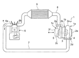
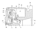
図1は、一実施形態に係るターボチャージャの全体構成を示す図である。図2は、一実施形態に係るターボチャージャの排気タービンの詳細構造を示す断面図である。 FIG. 1 is a diagram showing an entire configuration of a turbocharger according to an embodiment. FIG. 2 is a cross-sectional view showing a detailed structure of an exhaust turbine of a turbocharger according to an embodiment.
図1に示すターボチャージャ1は、自動車用のターボチャージャであり、自動車用エンジン6に装備されている。ターボチャージャ1は排気タービン1a、軸受台1b及びコンプレッサ1cで構成されている。排気タービン1aは、後で詳述する膨張タービン10A又は膨張タービン10Bによって構成されている。排気タービン1aは、タービンハウジング2aを有し、軸受台1bは軸受ハウジング2bを有し、コンプレッサ1cはコンプレッサハウジング2cを有している。
これらハウジングの内部に中心軸3がターボチャージャ1の軸方向に沿って設けられ、中心軸3は軸受(不図示)によって回転自在に支持されている。タービンハウジング2a側に位置する中心軸3の一端にタービンホイール4が固定され、コンプレッサハウジング2c側に位置する中心軸3の他端にコンプレッサホイール5が固定されている。The
Inside these housings, a
自動車用エンジン6の排気口6aに排気管7が接続され、排気管7の他端はタービンハウジング2aの入口ケーシング2dに接続されている。コンプレッサハウジング2cの出口ケーシング2gに給気管8が接続され、給気管8の他端は自動車用エンジン6の給気口6bに接続されている。
排気口6aから排出された排ガスeは排気管7を経て、作動流体としてタービンハウジング2aのスクロール部に接線方向に流入し、タービンホイール4を回転させた後、出口開口2eから流出する。An
Exhaust gas e discharged from the
タービンホイール4の回転は中心軸3を介してコンプレッサホイール5に伝わり、コンプレッサホイール5の回転によってコンプレッサハウジング2cの入口開口2fから空気aが吸入される。入口開口2fから吸入された空気aはコンプレッサホイール5で圧縮され、コンプレッサハウジング2cの出口ケーシング2gから給気管8に吐出される。給気管8に吐出された高圧空気はインタークーラ9で冷却された後、給気口6bから自動車用エンジン6の燃焼室(不図示)に供給される。 The rotation of the
なお、図1に示した例示的な実施形態では、ターボチャージャ1の排気タービン(膨張タービン)1aが排ガスのみで駆動されるようになっているが、他の実施形態では、排ガスを主駆動源とし、モータを補助駆動源としてもよい。 In the exemplary embodiment shown in FIG. 1, the exhaust turbine (expansion turbine) 1a of the
また、図2に示す例示的な実施形態では、排気タービン1aのタービンハウジング2aと軸受ハウジング2bとが結合具16で結合されている。軸受ハウジング2bに設けられ中心軸3を回転自在に支持する軸受20には、潤滑油路22から潤滑油rが供給される。なお、排気タービン1aとは反対側で軸受ハウジング2bに隣接してコンプレッサハウジング2c(図1参照)が設けられている。
前記ハウジング内にターボチャージャ1の軸方向に沿って設けられた中心軸3のタービン側端部には、タービンホイール4が固定されている。タービンホイール4は、中心軸3に固定されたハブ26と、ハブ26の外表面(ハブ面26a)に周方向に放射状に固定された複数の動翼28とで構成されている。
Also, in the exemplary embodiment shown in FIG. 2, the
A
タービンハウジング2aには、作動流体として排ガスeが導入されるスクロール部30が形成され、スクロール部30の内部に排ガスeが導入される渦巻き形状の空間sが形成されている。タービンハウジング2aは、タービンハウジング2aの外形を画定する外殻部12と、空間sの下流端付近に設けられるノズルプレート32と、ノズルプレート32に対向して設けられるノズルマウント34とを有する。
ノズルプレート32とノズルマウント34との間に、空間sに連通する流路fが形成されている。流路fに複数の可変ノズル36が中心軸3の周方向(排気タービン1aの周方向)に配置され、これら複数の可変ノズル36は動翼28の周囲に間隔を空けて配置されている。In the
A flow passage f communicating with the space s is formed between the
複数の可変ノズル36には夫々回動軸38が一体に結合されており、各可変ノズル36の回動軸38はノズルマウント34に形成された貫通孔からノズルマウント34の背面側に形成された空間に突出している。ノズルマウント34の背面側で、各回動軸38は同期機構40及び伝導軸(不図示)を介して軸受ハウジング2bの外部に設けられたアクチュエータ(不図示)に接続されている。
該アクチュエータを稼働させることで、複数の可変ノズル36を回動軸38を中心に同期して回動させることができる。複数の可変ノズル36を同期して回動させることで、空間sを通過した排ガスeが流路fを通過して動翼28に流入する際に、流路fの流路面積を変化させることができる。A
By operating the actuator, the plurality of
ノズルプレート32の一部は動翼28のチップ28aを覆うシュラウド壁面32aを構成している。タービンハウジング2aのノズルプレート32の壁面は、シュラウド壁面32aを含む第1壁面を構成し、ノズルプレート32に対向したタービンハウジング2aのノズルマウント34の壁面は第2壁面を構成している。これら、タービンハウジング2aの第1壁面及び第2壁面については、後で詳述する。
流路fは中心軸3の軸線Cと直交する方向、即ち、排気タービン1aの半径方向に沿って形成されており、排気タービン1aはラジアルタービンを構成している。
排気管7からスクロール部30の空間sに流入した排ガスeは、流路fに接線方向に流入する。流路fに流入した排ガスeは動翼28に達してタービンホイール4及び中心軸3を回転し、その後、中心軸3の軸線C上に形成された出口開口42から流出する。A part of the
The flow path f is formed in a direction orthogonal to the axis C of the
The exhaust gas e flowing from the
以下、排気タービン1aとして用いることができる膨張タービンの可変ノズル及び動翼周辺の構造について説明する。 Hereinafter, the structure around the variable nozzle and the moving blade of the expansion turbine that can be used as the
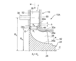
図3は、一実施形態に係る膨張タービンの可変ノズル及び動翼周辺の構造を示す断面図である。図4は、他の実施形態に係る膨張タービンの可変ノズル及び動翼周辺の構造を示す断面図である。 FIG. 3 is a cross-sectional view showing the structure around the variable nozzle and the moving blade of the expansion turbine according to one embodiment. FIG. 4 is a cross-sectional view showing a structure around a variable nozzle and a moving blade of an expansion turbine according to another embodiment.
幾つかの実施形態では、図3及び4に示すように、膨張タービン10(10A、10B)のタービンハウジング13は、動翼28のチップ28aに対向するシュラウド部(シュラウド壁面32a)を含む第1壁面50と、作動流体wの流路fを挟んで第1壁面50に対向する第2壁面52とを有する。図3及び図4に示す膨張タービン10(10A,10B)では、可変ノズル36の出口における翼高さは動翼28の入口における翼高さより大きく形成されている。また、可変ノズル36の出口の下流側でかつ動翼28の入口の上流側の第1壁面50に、作動流体の下流側に向かって流路fの流路高さが狭まるように、第2壁面52に向かって突出する突出部44,54が形成されている。図3及び図4に示す例示的な実施形態では、突出部44,54は、膨張タービン10の軸方向(軸線Cの方向)に対して傾斜した平面形状のテーパ面44a,54aを有する。 In some embodiments, as shown in FIGS. 3 and 4, the
突出部44,54の突出量は、突出部44の先端が動翼28の入口(前縁28b)におけるチップ28aを越えて第2壁面52側に突出しないように設定されている。即ち、動翼28の前縁28bにおける動翼根本の軸方向位置(前縁28bとタービンホイール24のハブ26のハブ面26aとの交点)を原点Oとし、動翼28の前縁28bにおけるチップ28aの軸方向位置をXtとしたとき、突出部44の先端の軸方向位置Xpは、0<Xt≦Xpを満たしている。
なお、図3に示す例示的な実施形態では、突出部44の先端の軸方向位置Xpが、動翼28の前縁28bにおけるチップ28aの軸方向位置X t と一致している(即ち、Xp=Xtの条件を満たす)。一方、図4に示す例示的な実施形態では、突出部44の先端の軸方向位置Xpが、動翼28の前縁28bにおけるチップ28aの軸方向位置X t よりもシュラウド側に後退している(即ち、Xp>Xtの条件を満たす)。
The amount of protrusion of the
In the exemplary embodiment shown in FIG. 3, the axial position X p of the distal end of the projecting
幾つかの実施形態では、突出部44,54のテーパ面44a,54aは軸方向に対して40度以下の角度で傾斜している。 In some embodiments, the
また、幾つかの実施形態では、図3及び図4に示すように、軸線Cから回動軸38の軸線までの半径方向の距離RSと、軸線Cから動翼28の入口(前縁28b)までの距離R Rとの比は、1.4≦RS/RRの条件を満たしている。
また、突出部44,54より上流側のシュラウド壁32aには、可変ノズル36の熱膨張による伸びを許容するため、最大開度時の可変ノズル36の出口端と突出部44,54(テーパ面44a,54a)との間に伸び代hが残るようになっている。 Also, in some embodiments, as shown in FIGS. 3 and 4, the radial distance R from axis C to the axis of
Further, in the
かかる構成において、空間sから流路fに流入した作動流体wは可変ノズル36の開度調整により流量が調節される。可変ノズル36の出口で、第1壁面50(シュラウド側)に近い領域を流れる作動流体は、図5中の破線で示すように、突出部44,54の外表面(テーパ面44a,54a)に沿って流れる際に第2壁面52側へ寄せられ、この状態で動翼28の翼高さ方向で比較的均一に動翼28間の流路を流れ、タービンホイール24を回転させた後、出口開口42に流出する。 In such a configuration, the flow rate of the working fluid w flowing from the space s into the flow path f is adjusted by adjusting the opening degree of the
上述した実施形態では、突出部44,54の先端が動翼28の入口のチップ28aを越えて第2壁面52側に突出しないように設定されている。即ち、動翼28の前縁28bにおける動翼根本の軸方向位置(前縁28bとタービンホイールのハブ26のハブ面26aとの交点)を原点Oとし、チップ28aの軸方向(軸線Cの方向)位置をXtとしたとき、突出部44,54の先端の軸方向位置Xpは、0<Xt≦Xpを満たしているので、突出部44,54による縮流効果に起因した動翼28の入口における実効流路面積の低下を抑制できる。そのため、所期の動翼性能が得られやすくなり、タービン効率を高く維持できる。
In the embodiment described above, the tips of the
また、テーパ面44a,54aが軸方向に対してなす角度が40度以下であるため、動翼28の入口でテーパ面44a,54aに沿って作動流体wを第2壁面52側(ハブ側)へ十分寄せることができ、そのため、第1壁面50側(シュラウド壁32a側)への作動流体wの偏流が抑制される。これによって、動翼出口における流速分布を均一化し、混合損失を抑制することで、タービン効率が向上する。 Further, since the angle formed by the
また、軸線Cから回動軸38の軸線までの半径方向の距離RSと、軸線Cから前縁28bまでの距離RRとの比が、1.4≦RS/RRであるので、可変ノズル36の出口から動翼28の入口までの距離が広がり、この部分の距離が広がることで、可変ノズル出口側で作動流体wの流速低下が起り、静圧の低下を抑制できる。
そのため、可変ノズル36の圧力面と負圧面間の圧力差を低減できるので、クリアランスフローを抑制でき、タービン効率を向上できる。特に、小開度域では、流れ損失全体に占めるクリアランスフローの抑制によるタービン効率向上効果が大きい。
Further, since the ratio of the radial distance R S from the axis C to the axis of the
Therefore, since the pressure difference between the pressure surface and the suction surface of the
また、上述した実施形態によれば、可変ノズル36の出口側翼高さを動翼28の入口側翼高さより大きくしたことで、隣接する可変ノズル36間の作動流体wの流路fにおけるスロート面積を増大させることができる。よって、可変ノズル36が大開度域のとき動翼28に流入する作動流体wの流量(最大流量)を十分に確保できる。
また、突出部44,54によって作動流体wは第2壁面52側(ハブ側)へ寄せられ、第1壁面50側(シュラウド側)への偏流が抑制される。そのため、動翼28の出口で膨張タービン10(10A,10B)の径方向における流速分布(流速Vの径方向分布)の不均一性が緩和され、混合損失が低減する。従って、可変ノズル36が小開度域にある場合でも、タービン効率を高く維持できる。
これによって、スクロール部の形状に依存することなく、可変ノズル36が小開度域のときのタービン効率を向上できると共に、可変ノズル36が大開度域のときの動翼28へ流入する作動流体wの流量(最大流量)を確保できる。Further, according to the above-described embodiment, by setting the outlet side blade height of the
Further, the working fluid w is moved to the
Thus, the turbine efficiency can be improved when the
図6及び図7は従来の膨張タービンを示しており、本実施形態を示す図3〜図5に対応する図である。一般に、可変ノズル36が小開度域のときは、作動流体wは強い旋回成分を持ちながら動翼28に流れ込み、作動流体wの半径方向の流速成分は小さい。
従来の膨張タービン100は、可変ノズル36の出口側翼高さと動翼28の入口側翼高さとは同等であり、かつテーパ面44a(54a)及び突出部44(54)が形成されていない。そのため、図7に示すように、可変ノズル36の小開度領域において、動翼28に流入する作動流体wが持つ旋回成分に起因した遠心力により、作動流体wはシュラウド壁32aの壁面を含む第1壁面50側に押し付けられやすい。
従って、作動流体wが第1壁面50側に押し付けられると、動翼28の出口において、作動流体wの流れは第1壁面50側に偏り、第1壁面50側で流速Vが大きく、第2壁面52側で流速が小さくなる。その結果、動翼28の下流側で流速不均衡を解消するように作動流体wが広がり、混合損失が起こりやすい。6 and 7 show a conventional expansion turbine, which corresponds to FIGS. 3 to 5 showing the present embodiment. In general, when the
In the
Therefore, when the working fluid w is pressed to the
なお、上述した実施形態は本発明をラジアルタービンに適用した例であるが、本発明の適用対象はラジアルタービンに限定されず、例えば、斜流タービン及び該斜流タービンを有するターボチャージャにも適用できる。 The embodiment described above is an example in which the present invention is applied to a radial turbine, but the application target of the present invention is not limited to a radial turbine, and is applied to, for example, a mixed flow turbine and a turbocharger having the mixed flow turbine. it can.
本発明の少なくとも一態様によれば、可変ノズルが小開度域のときのタービン効率の低下を抑制すると共に、可変ノズルが大開度域のときの作動流体の流量を確保し、併せて、動翼性能の低下を抑制し、タービン効率の低下を抑制できる膨張タービンを実現できる。 According to at least one aspect of the present invention, the decrease in turbine efficiency when the variable nozzle is in the small opening range is suppressed, and the flow rate of the working fluid when the variable nozzle is in the large opening range is secured. It is possible to realize an expansion turbine capable of suppressing the decrease in blade performance and suppressing the decrease in turbine efficiency.
1 ターボチャージャ
1a 排気タービン
1b 軸受台
1c コンプレッサ
2a、13 タービンハウジング
12 外殻部
2d 入口ケーシング
2e、42 出口開口
2b 軸受ハウジング
2c コンプレッサハウジング
2f 入口開口
2g 出口ケーシング
3 中心軸
4 タービンホイール
5 コンプレッサホイール
6 自動車用エンジン
6a 排気口
6b 給気口
7 排気管
8 給気管
9 インタークーラ
10A、10B、100 膨張タービン
16 結合具
20 軸受
22 潤滑油路
26 ハブ
26a ハブ面
28 動翼
28a チップ
28b 前縁
30 スクロール部
32 ノズルプレート
32a シュラウド壁面
34 ノズルマウント
36 可変ノズル
38 回動軸
40 同期機構
42 出口開口
44、54 突出部
44a、54a テーパ面
50 第1壁面
52 第2壁面
C 軸線
a 空気
e 排ガス
f 流路
h 伸び代
r 潤滑油
s 空間
w 作動流体
1
Claims (9)
前記作動流体が導入されるスクロール部を含むタービンハウジングと、
前記タービンハウジング内において前記膨張タービンの周方向に間隔を空けて配置され、前記スクロール部を通過した前記作動流体の流路面積が変化するように回動軸周りに回動可能に構成された複数の可変ノズルと、
前記可変ノズルの下流側に位置する動翼を複数有し、前記タービンハウジング内に回転自在に設けられたタービンホイールと、を備え、
前記タービンハウジングは、当該タービンハウジングの外形を画定する外殻と、ノズルプレートと、前記ノズルプレートに対向して設けられるノズルマウントとを含み、
前記ノズルプレートは、前記動翼のチップに対向するシュラウド部と、前記タービンの径方向に沿って延在する平坦面部とを含む第1壁面を有し、前記ノズルマウントは、前記作動流体の流路を挟んで前記第1壁面に対向する第2壁面であって、前記タービンの径方向に沿って延在する第2壁面を有し、
前記可変ノズルの出口側の翼高さは前記動翼の入口側の翼高さより大きく、
前記シュラウド部は、
前記可変ノズルの出口の下流側かつ前記動翼の入口の上流側において、前記作動流体の流路高さが下流側に向かって狭まるように、前記第2壁面に向かって突出する環状の突出部であって、前記突出部の先端が前記動翼の前縁よりも上流側、且つ前記平坦面部よりも前記第2壁面側に位置する突出部と、
前記膨張タービンの軸線方向に沿って延在する直線部、及び前記突出部の先端から前記直線部の上流端に向かって、途中に変曲点を有することなく、曲線状に延在する曲線部、を有するシュラウド壁と、を有し、
前記突出部の突出量は、前記突出部の先端が前記動翼の前記入口の前記チップを越えて前記第2壁面側に突出しないように設定されていることを特徴とする膨張タービン。 An expansion turbine for recovering power from energy of a working fluid, comprising:
A turbine housing including a scroll portion into which the working fluid is introduced;
A plurality of members arranged at intervals in the circumferential direction of the expansion turbine in the turbine housing, and configured to be rotatable around a rotation axis such that a flow passage area of the working fluid passing through the scroll portion changes. Variable nozzle, and
A plurality of moving blades located downstream of the variable nozzle, and a turbine wheel rotatably provided in the turbine housing;
The turbine housing includes an outer shell defining an outer shape of the turbine housing, a nozzle plate, and a nozzle mount provided opposite to the nozzle plate.
The nozzle plate has a first wall surface including a shroud portion facing the tip of the moving blade and a flat surface portion extending along a radial direction of the turbine, and the nozzle mount is configured to flow the working fluid A second wall surface facing the first wall surface across the passage, the second wall surface extending along a radial direction of the turbine ;
The blade height on the outlet side of the variable nozzle is greater than the blade height on the inlet side of the moving blade,
The shroud portion is
On the downstream side of the outlet of the variable nozzle and on the upstream side of the inlet of the moving blade, an annular protrusion projecting toward the second wall surface so that the flow channel height of the working fluid narrows toward the downstream side A protrusion whose tip end is located upstream of the front edge of the moving blade and closer to the second wall than the flat surface portion ;
A straight portion extending along the axial direction of the expansion turbine, and a curved portion extending curvilinearly from the tip end of the protrusion toward the upstream end of the straight portion without having an inflection point on the way And a shroud wall having
An expansion turbine characterized in that an amount of projection of the projection is set so that a tip end of the projection does not project beyond the tip of the inlet of the moving blade to the second wall surface side.
前記動翼の前記入口における根本の軸方向位置を原点とし、前記動翼の前記入口における前記動翼の前記チップの軸方向位置をXtとしたとき、前記突出部の先端の軸方向位置Xpは0<Xt≦Xpの関係を満たしていることを特徴とする請求項1に記載の膨張タービン。 The expansion turbine is a radial turbine in which the working fluid flows into the inlet of the moving blade along a radial direction of the expansion turbine,
The origin of the axial position of the root of the inlet of the moving blade, when the axial position of the rotor blade of the tip in the inlet of the moving blade and the X t, the axial position X of the tip of the projecting portion expansion turbine according to claim 1 p is characterized in that satisfy the relationship of 0 <X t ≦ X p.
前記テーパ面が前記膨張タービンの軸方向に対してなす角度が40度以下であることを特徴とする請求項2に記載の膨張タービン。 The first wall surface has a tapered surface inclined with respect to the radial direction, and the projecting portion is formed by the tapered surface.
The expansion turbine according to claim 2, wherein the angle which said taper side makes to the axial direction of said expansion turbine is 40 degrees or less.
前記膨張タービンによって駆動されて前記内燃機関への吸気を圧縮するように構成されたコンプレッサと、を備えていることを特徴とするターボチャージャ。 9. An expansion turbine according to any one of the preceding claims, which is adapted to be driven by exhaust gas from an internal combustion engine,
A compressor driven by said expansion turbine and configured to compress intake air to said internal combustion engine.
Applications Claiming Priority (1)
| Application Number | Priority Date | Filing Date | Title |
|---|---|---|---|
| PCT/JP2014/072571 WO2016031017A1 (en) | 2014-08-28 | 2014-08-28 | Expansion turbine and turbocharger |
Publications (2)
| Publication Number | Publication Date |
|---|---|
| JPWO2016031017A1 JPWO2016031017A1 (en) | 2017-04-27 |
| JP6426191B2 true JP6426191B2 (en) | 2018-11-21 |
Family
ID=55398955
Family Applications (1)
| Application Number | Title | Priority Date | Filing Date |
|---|---|---|---|
| JP2016545164A Active JP6426191B2 (en) | 2014-08-28 | 2014-08-28 | Expansion turbine and turbocharger |
Country Status (5)
| Country | Link |
|---|---|
| US (1) | US10364689B2 (en) |
| EP (1) | EP3147464B1 (en) |
| JP (1) | JP6426191B2 (en) |
| CN (1) | CN106715838B (en) |
| WO (1) | WO2016031017A1 (en) |
Families Citing this family (8)
| Publication number | Priority date | Publication date | Assignee | Title |
|---|---|---|---|---|
| USD835157S1 (en) * | 2016-10-28 | 2018-12-04 | Hamburger's Specialty Vehicles, Inc. | Supercharger system |
| USD811438S1 (en) * | 2016-10-28 | 2018-02-27 | Hamburger's Specialty Vehicles, Inc. | Supercharger system |
| USD808436S1 (en) * | 2016-10-28 | 2018-01-23 | Hamburger's Specialty Vehicles, Inc. | Supercharger system |
| USD886866S1 (en) * | 2017-10-31 | 2020-06-09 | Ryan Savage | Dual turbo charger kit |
| JP6651599B2 (en) * | 2017-11-30 | 2020-02-19 | 三菱重工業株式会社 | Variable nozzle mechanism and rotating machine equipped with the same |
| CN111655987B (en) * | 2018-02-28 | 2022-05-27 | 三菱重工发动机和增压器株式会社 | Radial turbine and turbocharger |
| JP7107433B2 (en) | 2019-04-01 | 2022-07-27 | 株式会社Ihi | Variable displacement turbocharger |
| DE112020005428T5 (en) | 2020-02-17 | 2022-08-25 | Mitsubishi Heavy Industries Engine & Turbocharger, Ltd. | Variable nozzle device, turbine and turbocharger |
Family Cites Families (10)
| Publication number | Priority date | Publication date | Assignee | Title |
|---|---|---|---|---|
| JPS6065207A (en) | 1983-09-21 | 1985-04-15 | Nissan Motor Co Ltd | Variable capacity radial turbine |
| JPS60153403A (en) | 1984-01-20 | 1985-08-12 | Nissan Motor Co Ltd | Variable capacity radial turbine |
| JPS62101038U (en) | 1985-12-16 | 1987-06-27 | ||
| JPH057461Y2 (en) | 1986-03-20 | 1993-02-25 | ||
| JP3534728B2 (en) | 2001-10-19 | 2004-06-07 | 三菱重工業株式会社 | Scroll structure of radial turbine |
| JP4468286B2 (en) | 2005-10-21 | 2010-05-26 | 三菱重工業株式会社 | Exhaust turbocharger |
| GB0805519D0 (en) | 2008-03-27 | 2008-04-30 | Cummins Turbo Tech Ltd | Variable geometry turbine |
| JP2011149306A (en) | 2010-01-20 | 2011-08-04 | Denso Corp | Turbocharger |
| JP5344082B2 (en) | 2010-03-18 | 2013-11-20 | トヨタ自動車株式会社 | Centrifugal compressor and turbocharger |
| JP2012002140A (en) | 2010-06-17 | 2012-01-05 | Ihi Corp | Turbine and supercharger |
-
2014
- 2014-08-28 EP EP14900922.7A patent/EP3147464B1/en active Active
- 2014-08-28 JP JP2016545164A patent/JP6426191B2/en active Active
- 2014-08-28 CN CN201480079723.3A patent/CN106715838B/en active Active
- 2014-08-28 WO PCT/JP2014/072571 patent/WO2016031017A1/en active Application Filing
- 2014-08-28 US US15/314,688 patent/US10364689B2/en active Active
Also Published As
| Publication number | Publication date |
|---|---|
| EP3147464A1 (en) | 2017-03-29 |
| US20170198593A1 (en) | 2017-07-13 |
| EP3147464B1 (en) | 2019-07-24 |
| CN106715838B (en) | 2018-12-04 |
| JPWO2016031017A1 (en) | 2017-04-27 |
| WO2016031017A1 (en) | 2016-03-03 |
| US10364689B2 (en) | 2019-07-30 |
| EP3147464A4 (en) | 2017-06-14 |
| CN106715838A (en) | 2017-05-24 |
Similar Documents
| Publication | Publication Date | Title |
|---|---|---|
| JP6426191B2 (en) | Expansion turbine and turbocharger | |
| US9732756B2 (en) | Centrifugal compressor | |
| JP6067095B2 (en) | Centrifugal compressor | |
| KR102076638B1 (en) | Mixed-flow turbocharger with variable turbine geometry | |
| KR20060043038A (en) | Compressor | |
| JP2005299660A (en) | Variable-form turbine | |
| JP2005299660A5 (en) | ||
| CN102116317B (en) | System and apparatus relating to compressor operation in turbine engines | |
| WO2016051531A1 (en) | Turbine | |
| JP2017535719A (en) | Turbomachines including vanes and methods of assembling such turbomachines | |
| JPWO2018131167A1 (en) | Turbine wheel, turbine and turbocharger | |
| US11047256B2 (en) | Variable nozzle unit and turbocharger | |
| JP2011132810A (en) | Moving blade of radial turbine | |
| JP6606613B2 (en) | Turbocharger and turbocharger nozzle vanes and turbines | |
| JP6651404B2 (en) | Turbo machinery | |
| CN111911455A (en) | Impeller of centrifugal compressor, centrifugal compressor and turbocharger | |
| WO2018123045A1 (en) | Turbine and turbocharger | |
| JP7008789B2 (en) | Radius inflow turbine and turbocharger | |
| JPWO2019123565A1 (en) | Turbine and turbocharger | |
| JP6605147B2 (en) | Turbocharger and turbocharger nozzle vanes and turbines | |
| JP2022046381A (en) | Turbine wheel, turbine and turbocharger | |
| CN111448374B (en) | Turbine and turbocharger | |
| WO2020188763A1 (en) | Centrifugal compressor and turbocharger | |
| JP2023118180A (en) | Turbine and supercharger | |
| JP2008163761A (en) | Radial turbine |
Legal Events
| Date | Code | Title | Description |
|---|---|---|---|
| A524 | Written submission of copy of amendment under article 19 pct |
Free format text: JAPANESE INTERMEDIATE CODE: A527 Effective date: 20161018 |
|
| A621 | Written request for application examination |
Free format text: JAPANESE INTERMEDIATE CODE: A621 Effective date: 20161018 |
|
| A131 | Notification of reasons for refusal |
Free format text: JAPANESE INTERMEDIATE CODE: A131 Effective date: 20170609 |
|
| A521 | Request for written amendment filed |
Free format text: JAPANESE INTERMEDIATE CODE: A523 Effective date: 20170714 |
|
| A02 | Decision of refusal |
Free format text: JAPANESE INTERMEDIATE CODE: A02 Effective date: 20170901 |
|
| A521 | Request for written amendment filed |
Free format text: JAPANESE INTERMEDIATE CODE: A523 Effective date: 20171130 |
|
| A911 | Transfer to examiner for re-examination before appeal (zenchi) |
Free format text: JAPANESE INTERMEDIATE CODE: A911 Effective date: 20171208 |
|
| A912 | Re-examination (zenchi) completed and case transferred to appeal board |
Free format text: JAPANESE INTERMEDIATE CODE: A912 Effective date: 20180112 |
|
| A521 | Request for written amendment filed |
Free format text: JAPANESE INTERMEDIATE CODE: A523 Effective date: 20180725 |
|
| A61 | First payment of annual fees (during grant procedure) |
Free format text: JAPANESE INTERMEDIATE CODE: A61 Effective date: 20181024 |
|
| R150 | Certificate of patent or registration of utility model |
Ref document number: 6426191 Country of ref document: JP Free format text: JAPANESE INTERMEDIATE CODE: R150 |