EP3147464A1 - Expansion turbine and turbocharger - Google Patents
Expansion turbine and turbocharger Download PDFInfo
- Publication number
- EP3147464A1 EP3147464A1 EP14900922.7A EP14900922A EP3147464A1 EP 3147464 A1 EP3147464 A1 EP 3147464A1 EP 14900922 A EP14900922 A EP 14900922A EP 3147464 A1 EP3147464 A1 EP 3147464A1
- Authority
- EP
- European Patent Office
- Prior art keywords
- turbine
- wall surface
- working fluid
- inlet
- turbine blades
- Prior art date
- Legal status (The legal status is an assumption and is not a legal conclusion. Google has not performed a legal analysis and makes no representation as to the accuracy of the status listed.)
- Granted
Links
- 239000012530 fluid Substances 0.000 claims abstract description 62
- 238000011144 upstream manufacturing Methods 0.000 claims abstract description 7
- 238000002485 combustion reaction Methods 0.000 claims description 8
- 230000008859 change Effects 0.000 claims description 3
- 230000007423 decrease Effects 0.000 description 18
- 230000000694 effects Effects 0.000 description 8
- 238000010586 diagram Methods 0.000 description 4
- 238000009826 distribution Methods 0.000 description 4
- 239000000314 lubricant Substances 0.000 description 4
- 230000008878 coupling Effects 0.000 description 2
- 238000010168 coupling process Methods 0.000 description 2
- 238000005859 coupling reaction Methods 0.000 description 2
- 230000007246 mechanism Effects 0.000 description 2
- 238000000034 method Methods 0.000 description 2
- 230000004044 response Effects 0.000 description 2
- 230000003068 static effect Effects 0.000 description 2
- 230000001629 suppression Effects 0.000 description 2
- 230000005540 biological transmission Effects 0.000 description 1
- 230000015572 biosynthetic process Effects 0.000 description 1
- 239000000446 fuel Substances 0.000 description 1
- 239000000463 material Substances 0.000 description 1
- 230000004048 modification Effects 0.000 description 1
- 238000012986 modification Methods 0.000 description 1
- 230000009467 reduction Effects 0.000 description 1
- 238000000926 separation method Methods 0.000 description 1
- 230000001360 synchronised effect Effects 0.000 description 1
- 238000009827 uniform distribution Methods 0.000 description 1
Images


Classifications
-
- F—MECHANICAL ENGINEERING; LIGHTING; HEATING; WEAPONS; BLASTING
- F01—MACHINES OR ENGINES IN GENERAL; ENGINE PLANTS IN GENERAL; STEAM ENGINES
- F01D—NON-POSITIVE DISPLACEMENT MACHINES OR ENGINES, e.g. STEAM TURBINES
- F01D9/00—Stators
- F01D9/02—Nozzles; Nozzle boxes; Stator blades; Guide conduits, e.g. individual nozzles
- F01D9/026—Scrolls for radial machines or engines
-
- F—MECHANICAL ENGINEERING; LIGHTING; HEATING; WEAPONS; BLASTING
- F02—COMBUSTION ENGINES; HOT-GAS OR COMBUSTION-PRODUCT ENGINE PLANTS
- F02B—INTERNAL-COMBUSTION PISTON ENGINES; COMBUSTION ENGINES IN GENERAL
- F02B37/00—Engines characterised by provision of pumps driven at least for part of the time by exhaust
-
- F—MECHANICAL ENGINEERING; LIGHTING; HEATING; WEAPONS; BLASTING
- F01—MACHINES OR ENGINES IN GENERAL; ENGINE PLANTS IN GENERAL; STEAM ENGINES
- F01D—NON-POSITIVE DISPLACEMENT MACHINES OR ENGINES, e.g. STEAM TURBINES
- F01D25/00—Component parts, details, or accessories, not provided for in, or of interest apart from, other groups
- F01D25/24—Casings; Casing parts, e.g. diaphragms, casing fastenings
-
- F—MECHANICAL ENGINEERING; LIGHTING; HEATING; WEAPONS; BLASTING
- F02—COMBUSTION ENGINES; HOT-GAS OR COMBUSTION-PRODUCT ENGINE PLANTS
- F02B—INTERNAL-COMBUSTION PISTON ENGINES; COMBUSTION ENGINES IN GENERAL
- F02B39/00—Component parts, details, or accessories relating to, driven charging or scavenging pumps, not provided for in groups F02B33/00 - F02B37/00
-
- F—MECHANICAL ENGINEERING; LIGHTING; HEATING; WEAPONS; BLASTING
- F04—POSITIVE - DISPLACEMENT MACHINES FOR LIQUIDS; PUMPS FOR LIQUIDS OR ELASTIC FLUIDS
- F04D—NON-POSITIVE-DISPLACEMENT PUMPS
- F04D25/00—Pumping installations or systems
- F04D25/02—Units comprising pumps and their driving means
- F04D25/04—Units comprising pumps and their driving means the pump being fluid-driven
-
- F—MECHANICAL ENGINEERING; LIGHTING; HEATING; WEAPONS; BLASTING
- F05—INDEXING SCHEMES RELATING TO ENGINES OR PUMPS IN VARIOUS SUBCLASSES OF CLASSES F01-F04
- F05D—INDEXING SCHEME FOR ASPECTS RELATING TO NON-POSITIVE-DISPLACEMENT MACHINES OR ENGINES, GAS-TURBINES OR JET-PROPULSION PLANTS
- F05D2240/00—Components
- F05D2240/10—Stators
- F05D2240/12—Fluid guiding means, e.g. vanes
-
- Y—GENERAL TAGGING OF NEW TECHNOLOGICAL DEVELOPMENTS; GENERAL TAGGING OF CROSS-SECTIONAL TECHNOLOGIES SPANNING OVER SEVERAL SECTIONS OF THE IPC; TECHNICAL SUBJECTS COVERED BY FORMER USPC CROSS-REFERENCE ART COLLECTIONS [XRACs] AND DIGESTS
- Y02—TECHNOLOGIES OR APPLICATIONS FOR MITIGATION OR ADAPTATION AGAINST CLIMATE CHANGE
- Y02T—CLIMATE CHANGE MITIGATION TECHNOLOGIES RELATED TO TRANSPORTATION
- Y02T10/00—Road transport of goods or passengers
- Y02T10/10—Internal combustion engine [ICE] based vehicles
- Y02T10/12—Improving ICE efficiencies
Definitions
- the present disclosure relates to an expansion turbine provided with variable nozzles, and a turbocharger including the expansion turbine.
- variable geometry turbocharger including variable nozzles disposed on the inlet side of an expansion turbine, whereby a flow rate of a working fluid is adjustable by changing the opening degree of the variable nozzles.
- the variable geometry turbocharger can be operated in accordance with a change in the loads of an internal combustion engine, and a response performance is particularly high during low-load operation.
- a variable geometry turbocharger is characterized in that, when the opening degree of the variable nozzles is small, the turbine efficiency considerably decreases from a peak point (where the nozzle opening degree is near the intermediate opening-degree range). The turbine efficiency during the time when the nozzle opening degree is in the small opening-degree range affects the response performance considerably. Thus, it is desirable to improve the turbine efficiency in the small opening-degree range.
- an incidence angle is a difference between an inflow angle of a working fluid flowing into the variable nozzles and a leading-edge blade angle of the variable nozzles.
- narrowing the scroll section leads to an increase in the incidence angle during the time when the nozzle opening degree is in the large opening-degree range, which may raise a risk of flow separation on the blade surfaces of the variable nozzles, a decrease in the actual flow-path area, and reduction in the flow rate of the working fluid (maximum flow rate).
- Patent Document 1 discloses a turbine including an annular guide portion (guide surface) formed on an inlet side of turbine blades on a wall surface of a shroud of a turbine housing facing tips of the turbine blades, the guide portion being inclined toward the back-surface side of a turbine wheel in the radial direction of the turbine.
- a working fluid flowing into the turbine blades is attracted to the back-surface side of the turbine wheel by formation of the guide portion, which suppresses an exciting force generated by wake of the variable nozzles acting in the vicinity of the tips of the turbine blades, and thereby suppresses vibration of the turbine blades. Furthermore, a gap between the turbine blades and the wall surface of the shroud is blocked by the guide portion, and thereby a clearance flow via the gap is suppressed.
- Patent Document 1 JP2012-002140A
- the guide portion protrudes considerably toward a hub to reduce a clearance flow via a gap between the turbine blades and the wall surface of the shroud.
- the front end of the inlet of the turbine blades is partially covered by the tip of the guide portion, and the narrowest section of the flow path is positioned upstream of the inlet of the turbine blades.
- the working fluid does not flow into a part of the leading edges of the turbine blades due to the contraction-flow effect, which causes the turbine blades to fail to exert the predetermined performance, thus reducing the turbine efficiency.
- an object of at least one embodiment of the present invention is to provide an expansion turbine and a turbocharger whereby it is possible to suppress a decrease in the turbine efficiency when variable nozzles are in the small opening-degree range, to ensure a flow rate of a working fluid when the variable nozzles are in the large opening-degree range, and to draw out the predetermined performance of turbine blades to suppress a decrease in the turbine efficiency.
- the present invention it is possible to suppress a decrease in the turbine efficiency when the variable nozzles are in the small opening-degree range, to ensure a flow rate of a working fluid when the variable nozzles are in the large opening-degree range, and to reduce a decrease in the performance of the turbine blades to suppress a decrease in the turbine efficiency.
- an expression of relative or absolute arrangement such as “in a direction”, “along a direction”, “parallel”, “orthogonal”, “centered”, “concentric” and “coaxial” shall not be construed as indicating only the arrangement in a strict literal sense, but also includes a state where the arrangement is relatively displaced by a tolerance, or by an angle or a distance whereby it is possible to achieve the same function.
- an expression of an equal state such as “same” “equal” and “uniform” shall not be construed as indicating only the state in which the feature is strictly equal, but also includes a state in which there is a tolerance or a difference that can still achieve the same function.
- an expression of a shape such as a rectangular shape or a cylindrical shape shall not be construed as only the geometrically strict shape, but also includes a shape with unevenness or chamfered corners within the range in which the same effect can be achieved.
- a turbocharger an example of application of the present invention, will now be described.
- a turbocharger an example of application of the present invention, is not particularly limited and only needs to be a supercharger for forcedly sending intake air into an internal combustion engine.
- the turbocharger may be a turbocharger for an automobile, or a turbocharger for a ship.
- FIG. 1 is an overall configuration diagram of a turbocharger according to an embodiment.
- FIG. 2 is a detailed cross-sectional view of a structure of an exhaust turbine of a turbocharger according to an embodiment.
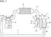
- the turbocharger 1 depicted in FIG. 1 is a turbocharger for an automobile, and is mounted to an automobile engine 6.
- the turbocharger 1 includes an exhaust turbine 1a, a bearing mount 1b, and a compressor 1c.
- the exhaust turbine 1a includes an expansion turbine 10A or an expansion turbine 10B described below in detail.
- the exhaust turbine 1a has a turbine housing 2a, the bearing mount 1b has a bearing housing 2b, and the compressor 1c has a compressor housing 2c.
- a center shaft 3 is disposed along the axial direction of the turbocharger 1 inside the above housings, and supported rotatably by a bearing (not depicted).
- a turbine wheel 4 is fixed to an end of the center shaft 3 disposed on the side of the turbine housing 2a, while a compressor wheel 5 is fixed to the other end of the center shaft 3 disposed on the side of the compressor housing 2c.
- An exhaust pipe 7 is connected to an exhaust port 6a of the automobile engine 6 at one end, and to an inlet casing 2d of the turbine housing 2a at the other end.
- An intake pipe 8 is connected to an outlet casing 2g of the compressor housing 2c at one end, and to an intake port 6b of the automobile engine 6 at the other end.
- Exhaust gas "e” discharged from the exhaust port 6a flows into a scroll section of the turbine housing 2a as a working fluid in the tangent direction via the exhaust pipe 7, rotates the turbine wheel 4, and exits through an outlet opening 2e.
- Rotation of the turbine wheel 4 is transmitted to the compressor wheel 5 via the center shaft 3, and rotation of the compressor wheel 5 takes in air “a” through an inlet opening 2f of the compressor housing 2c.
- Air “a” taken in through the inlet opening 2f is compressed by the compressor wheel 5, and is discharged from an outlet casing 2g of the compressor housing 2c to the intake pipe 8.
- High-pressure air discharged into the intake pipe 8 is cooled by an inter-cooler 9, and is supplied to a combustion chamber (not depicted) of the automobile engine 6 through the intake port 6b.
- exhaust turbine (expansion turbine) 1a of the turbocharger 1 is driven by exhaust gas alone in the exemplary embodiment illustrated in FIG. 1
- exhaust gas may be used as a main driving source and a motor may be employed as an auxiliary driving source, in another embodiment.
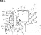
- the turbine housing 2a and the bearing housing 2b of the exhaust turbine 1a are coupled with a coupling unit 16.
- the bearing 20 disposed in the bearing housing 2b to support the center shaft 3 rotatably is supplied with lubricant oil "r" through a lubricant oil passage 22.
- the compressor 2c (see FIG. 1 ) is disposed adjoining to the bearing housing 2b on the side opposite from the exhaust turbine 1a.
- the turbine wheel 4 is fixed to the turbine-side end of the center shaft 3 disposed along the axial direction of the turbocharger 1 inside the housing.
- the turbine wheel 4 includes a hub 26 fixed to the center shaft 3, and a plurality of turbine blades 28 fixed in a radial fashion to an outer surface (hub surface 26a) of the hub 26 in the circumferential direction.
- a scroll section 30 for taking in exhaust gas “e” as a working fluid is formed on the turbine housing 2a, and a space “s” of a scroll shape for taking in exhaust gas “e” is formed inside the scroll section 30.
- the turbine housing 2a includes an outer shell portion 12 defining a profile of the turbine housing 2a, a nozzle plate 32 disposed in the vicinity of a downstream end of the space "s", and a nozzle mount 34 disposed so as to face the nozzle plate 32.
- a flow path "f" communicating with the space “s” is formed between the nozzle plate 32 and the nozzle mount 34.
- a plurality of variable nozzles 36 is disposed inside the flow path "f" in the circumferential direction of the center shaft 3 (the circumferential direction of the exhaust turbine 1a), and the variable nozzles 36 are disposed at intervals around the turbine blades 28.
- a rotation shaft 38 is integrally joined to each of the variable nozzles 36, and the rotation shaft 38 of each variable nozzle 36 protrudes from a through hole formed on the nozzle mount 34 into a space formed on the back-surface side of the nozzle mount 34.
- each rotation shaft 38 is connected to an actuator (not depicted) disposed outside the bearing housing 2b via a synchronization mechanism 40 and a transmission shaft (not depicted).
- the actuator is operated to rotate the plurality of variable nozzles 36 about the rotation shafts 38 in synchronization.
- the synchronized rotation of the variable nozzles 36 changes the flow-path area of the flow path "f" when the exhaust gas "e” from the space “s” passes through the flow path "f” to flow into the turbine blades 28.
- a part of the nozzle plate 32 forms a shroud wall surface 32a covering tips 28a of the turbine blades 28.
- the wall surface of the nozzle plate 32 of the turbine housing 2a forms the first wall surface including a shroud wall surface 32a, and the wall surface of the nozzle mount 34 of the turbine housing 2a facing the nozzle plate 32 forms the second wall surface.
- the first wall surface and the second wall surface of the turbine housing 2a will be described later.
- the flow path "f" is formed along a direction orthogonal to the axis C of the center shaft 3, that is, along the radial direction of the exhaust turbine 1a, and thereby the exhaust turbine 1a forms a radial turbine.
- variable nozzles and turbine blades of an expansion turbine which can be used as the exhaust turbine 1a.
- FIG. 3 is a cross-sectional view of a variable nozzle, a turbine blade, and their surrounding structure, of an expansion turbine according to an embodiment.
- FIG. 4 is a cross-sectional view of a variable nozzle, a turbine blade, and their surrounding structure, of an expansion turbine according to another embodiment.
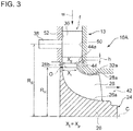
- a turbine housing 13 of the expansion turbine 10 (10A, 10B) includes a first wall surface 50 including a shroud section (shroud wall surface 32a) facing a tip 28a of the turbine blade 28, and a second wall surface 52 facing the first wall surface 50 across the flow path "f" of the working fluid "w".
- the blade height of the variable nozzle 36 at the outlet is greater than the blade height of the turbine blade 28 at the inlet.
- a protruding portion 44, 54 protruding toward the second wall surface 52 is formed on the first wall surface 50 downstream the outlet of the variable nozzle 36 and upstream the inlet of the turbine blade 28 so that the flow-path height of the flow path "f" reduces downstream in the flow direction of the working fluid.
- the protruding portion 44, 54 has a tapered surface 44a, 54a inclined from the axial direction of the expansion turbine 10 (from the direction of the axis C) in a flat shape.
- the protruding amount of the protruding portion 44, 54 is set so that the tip end of the protruding portion 44 does not protrude toward the second wall surface 52 over the tip 28a at the inlet (leading edge 28b) of the turbine blade 28.
- origin O is the axial position of the root of the turbine blade on the leading edge 28b of the turbine blade 28 (the intersection of the leading edge 28b and the hub surface 26a of the hub 26 of the turbine wheel 24)
- X t is the axial position of the tip 28a on the leading edge 28b of the turbine blade 28
- the axial position X p of the tip end of the protruding portion 44 satisfies a relationship 0 ⁇ X t ⁇ X p .
- the axial position X p of the tip end of the protruding portion 44 is receded toward the shroud from the axial position X t of the tip 28a on the leading edge 28b of the turbine blade 28 (i.e., a condition X p >X t is satisfied).
- the tapered surface 44a, 54a of the protruding portion 44, 54 is inclined from the axial direction by an angular degree of 40 degrees or less.
- a ratio of the distance Rs in the radial direction between the axis C and the axis of the rotation shaft 38 to the distance R R between the axis C and the inlet (leading edge 28b) of the turbine blade 28 satisfies a condition 1.4 ⁇ R S /R R .
- shroud wall 32a upstream of the protruding portion 44, 54 has an expansion allowance "h" between the protruding portion 44, 54 (tapered surface 44a, 54a) and an outlet end of the variable nozzle 36 in the position of the maximum opening degree, so as to provide room for thermal expansion of the variable nozzle 36.
- the working fluid "w” flowing into the flow path “f” from the space “s” has its flow rate adjusted by adjustment of the opening degree of the variable nozzle 36.
- a working fluid flowing through a region near the first wall surface 50 (shroud side) at the outlet of the variable nozzle 36 is attracted toward the second wall surface 52 when flowing along the outer surface (tapered surface 44a, 54a) of the protruding portion 44, 54.
- the working fluid flows through a flow path between the turbine blades 28 in a relatively uniform distribution in the blade-height direction of the turbine blades 28, rotates the turbine wheel 24, and exits through the outlet opening 42.
- the tip end of the protruding portion 44, 54 is set so as not to protrude toward the second wall surface 52 past the tip 28a at the inlet of the turbine blade 28.
- origin O is the axial position of the root of the turbine blade on the leading edge 28b of the turbine blade 28 (the intersection of the leading edge 28b and the hub surface 26a of the hub 26 of the turbine wheel)
- X t is the axial position of the tip 28a (position in the direction of axis C)
- the axial position X p of the tip end of the protruding portion 44, 54 satisfies a relationship 0 ⁇ X t ⁇ X p , and thereby it is possible to suppress a decrease in the effective flow-path area at the inlet of the turbine blade 28 due to the contraction-flow effect of the protruding portion 44, 54.
- a predetermined performance of the turbine blades can be more easily achieved, and it is possible to maintain a high turbine efficiency.
- the tapered surface 44a, 54a forms an angle of 40 degrees or less with the axial direction, the working fluid "w" can be attracted sufficiently toward the second wall surface 52 (hub side) along the tapered surface 44a, 54a at the inlet of the turbine blade 28, which suppresses a drift of the working fluid "w" toward the first wall surface 50 (the shroud wall 32a). In this way, a flow-velocity distribution becomes uniform at the outlet of the turbine blade and a mixing loss is suppressed, which improves the turbine efficiency.
- the blade height of the variable nozzle 36 at the outlet side is greater than the blade height of the turbine blade 28 at the inlet side, which makes it possible to increase the throat area of the flow path "f" of the working fluid "w” formed between two adjacent variable nozzles 36.
- the working fluid "w" is attracted toward the second wall surface 52 (hub side) due to the protruding portion 44, 54, and a drift toward the first wall surface 50 (the shroud) is suppressed.
- unevenness in the flow-velocity distribution in the radial direction (distribution of the flow velocity V in the radial direction) of the expansion turbine 10 (10A, 10B) is mitigated at the outlet of the turbine blade 28, which reduces a mixing loss. Accordingly, a high turbine efficiency can be maintained even if the variable nozzle 36 is in the small opening-degree range.
- FIGs. 6 and 7 are views of a typical expansion turbine, corresponding to FIGs. 3 and 5 showing the present embodiment.
- the working fluid "w" flows into the turbine blade 28 while having a strong swirling component when the variable nozzle 36 is in the small-opening region, but has a small flow-velocity component in the radial direction.
- the blade height of the variable nozzle 36 at the outlet side is substantially the same as the blade height of the turbine blade 28 at the inlet side, and the tapered surface 44a (54a) and the protruding portion 44 (54) are not formed.
- the working fluid "w" is likely to be attracted toward the first wall surface 50 including the wall surface of the shroud wall 32a, due to a centrifugal force generated by a swirling component of the working fluid "w" flowing into the turbine blade 28.
- the working fluid "w” gets closer to the side of the first wall surface 50, thus the flow velocity V being higher by the side of the first wall surface 50 and lower by the side of the second wall surface 52, at the outlet of the turbine blade 28.
- the working fluid "w” spreads out at the downstream side of the turbine blade 28 so as to cancel unevenness in the flow velocity, which is likely to cause a mixing loss.
- application of the present invention is not limited to a radial turbine, and may be a mixed-flow turbine and a turbocharger including the mixed-flow turbine, for instance.
- an expansion turbine whereby it is possible to suppress a decrease in the turbine efficiency when the variable nozzles are in the small opening-degree range, to ensure a flow rate of a working fluid when the variable nozzles are in the large opening-degree range, and to reduce a decrease in the performance of the turbine blade to suppress a decrease in the turbine efficiency.
Landscapes
- Engineering & Computer Science (AREA)
- Mechanical Engineering (AREA)
- General Engineering & Computer Science (AREA)
- Chemical & Material Sciences (AREA)
- Combustion & Propulsion (AREA)
- Supercharger (AREA)
- Control Of Turbines (AREA)
- Turbine Rotor Nozzle Sealing (AREA)
Abstract
Description
- The present disclosure relates to an expansion turbine provided with variable nozzles, and a turbocharger including the expansion turbine.
- In recent years, there is a remarkable trend to provide an internal combustion engine for an automobile with a turbocharger to improve fuel consumption. Among several types of turbochargers is a variable geometry turbocharger including variable nozzles disposed on the inlet side of an expansion turbine, whereby a flow rate of a working fluid is adjustable by changing the opening degree of the variable nozzles. Thus, the variable geometry turbocharger can be operated in accordance with a change in the loads of an internal combustion engine, and a response performance is particularly high during low-load operation.
- However, as depicted in
FIG. 8 , a variable geometry turbocharger is characterized in that, when the opening degree of the variable nozzles is small, the turbine efficiency considerably decreases from a peak point (where the nozzle opening degree is near the intermediate opening-degree range). The turbine efficiency during the time when the nozzle opening degree is in the small opening-degree range affects the response performance considerably. Thus, it is desirable to improve the turbine efficiency in the small opening-degree range. - To improve the turbine efficiency in the small opening-degree range, it is advantageous to reduce the incidence angle of the variable nozzles (an incidence angle is a difference between an inflow angle of a working fluid flowing into the variable nozzles and a leading-edge blade angle of the variable nozzles). Thus, to reduce the incidence angle, one may narrow a scroll section (that is, reduce the size of the scroll section) of a turbine housing in accordance with the leading-edge blade angle of the variable nozzles in the small opening-degree range.
- On the other hand, narrowing the scroll section leads to an increase in the incidence angle during the time when the nozzle opening degree is in the large opening-degree range, which may raise a risk of flow separation on the blade surfaces of the variable nozzles, a decrease in the actual flow-path area, and reduction in the flow rate of the working fluid (maximum flow rate).
- As described above, it is not easy to achieve both an improved turbine efficiency in the small opening-degree range of the variable nozzles and a sufficient maximum flow rate in the large opening-degree range of the variable nozzles, by simply adjusting the shape of the scroll section of the turbine housing. It is thus desirable to make use of techniques other than modification of the shape of the scroll section to satisfy the above two requirements.
- Although not intended to achieve both an improved turbine efficiency in the small opening-degree range of the variable nozzles and a sufficient maximum flow rate in the large opening-degree range, Patent Document 1 discloses a turbine including an annular guide portion (guide surface) formed on an inlet side of turbine blades on a wall surface of a shroud of a turbine housing facing tips of the turbine blades, the guide portion being inclined toward the back-surface side of a turbine wheel in the radial direction of the turbine.
- With the turbine disclosed in Patent Document 1, a working fluid flowing into the turbine blades is attracted to the back-surface side of the turbine wheel by formation of the guide portion, which suppresses an exciting force generated by wake of the variable nozzles acting in the vicinity of the tips of the turbine blades, and thereby suppresses vibration of the turbine blades. Furthermore, a gap between the turbine blades and the wall surface of the shroud is blocked by the guide portion, and thereby a clearance flow via the gap is suppressed.
- Patent Document 1:
JP2012-002140A - However, in the turbine disclosed in Patent Document 1, the guide portion protrudes considerably toward a hub to reduce a clearance flow via a gap between the turbine blades and the wall surface of the shroud. Thus, the front end of the inlet of the turbine blades is partially covered by the tip of the guide portion, and the narrowest section of the flow path is positioned upstream of the inlet of the turbine blades. The working fluid does not flow into a part of the leading edges of the turbine blades due to the contraction-flow effect, which causes the turbine blades to fail to exert the predetermined performance, thus reducing the turbine efficiency.
- In view of the above problems of typical techniques, an object of at least one embodiment of the present invention is to provide an expansion turbine and a turbocharger whereby it is possible to suppress a decrease in the turbine efficiency when variable nozzles are in the small opening-degree range, to ensure a flow rate of a working fluid when the variable nozzles are in the large opening-degree range, and to draw out the predetermined performance of turbine blades to suppress a decrease in the turbine efficiency.
-
- (1) An expansion turbine for recovering power from energy of a working fluid, according to at least one embodiment of the present invention, comprises: a turbine housing including a scroll section for taking in the working fluid; a plurality of variable nozzles disposed inside the turbine housing at intervals in a circumferential direction of the expansion turbine, each of the variable nozzles being configured to be rotatable about a rotation shaft so as to change an area of a flow path of the working fluid flowing from the scroll section; and a turbine wheel disposed rotatably inside the turbine housing, the turbine wheel including a plurality of turbine blades disposed downstream of the variable nozzles. The turbine housing has a first wall surface including a shroud section which faces tips of the turbine blades, and a second wall surface which faces the first wall surface across the flow path of the working fluid. A blade height of the variable nozzles at an outlet side is greater than a blade height of the turbine blades at an inlet side. The shroud section has a protruding portion protruding toward the second wall surface so as to reduce a height of the flow path of the working fluid toward downstream, at a downstream side of an outlet of the variable nozzles and an upstream side of an inlet of the turbine blades. A protruding amount of the protruding portion is set so that a tip end of the protruding portion does not protrude toward the second wall surface past the tips of the turbine blades at the inlet.
With the above configuration (1), the blade height of the variable nozzles at the outlet side is greater than the blade height of the turbine blades at the inlet side, which makes it possible to increase the throat area of the flow path of the working fluid formed between the variable nozzles. Thus, it is possible to ensure a sufficient flow rate (maximum flow rate) of the working fluid that flows into the turbine blades when the variable nozzles are in the large opening-degree range.
Furthermore, when the variable nozzles are in a small opening-degree range, the working fluid flowing into the turbine blades has a strong swirling component due to the small nozzle opening degree, but has a small flow-velocity component directed inward in the radial direction. Thus, in a typical expansion turbine, in the small opening-degree range of the variable nozzles, the working fluid is likely to be attracted toward the shroud (the first wall surface), due to a centrifugal force generated by the swirling component of the working fluid flowing into the turbine blades. Accordingly, if the working fluid is attracted toward the shroud wall surface, the flow of the working fluid gets closer to the side of the shroud, thus the flow velocity being higher by the side of the shroud and lower by the side of the hub (the second wall surface), at the outlet of the turbine blades. As a result, the working fluid spreads out at the downstream side of the turbine blades so as to cancel the unevenness in the flow velocity, which is likely to cause a mixing loss.
In this regard, with the above configuration (1), the shroud section has the protruding portion, and thus the working fluid flows along the protruding portion to be attracted toward the second wall surface (the hub), and a drift of the working fluid toward the first wall surface (the shroud) is suppressed. Thus, an unbalanced flow at the outlet of the turbine blades is mitigated and a mixing loss is reduced, which improves the turbine efficiency.
Accordingly, with the above configuration (1), in addition to the above described merit of ensuring the maximum flow rate in the large opening-degree range of the variable nozzles, it is possible to achieve a merit of improving the turbine efficiency in the small opening-degree range of the variable nozzles.
Furthermore, with the above configuration (1), the protruding amount of the protruding portion is set so that the tip end of the protruding portion does not protrude toward the second wall surface over the tips of the turbine blades at the inlet, and thus the working fluid flows into a broader range in the height direction of the turbine blades, which makes it possible to suppress a decrease in an effective flow-path area at the inlet of the turbine blades due to the contraction-flow effect of the protruding portion. Thus, a predetermined performance of the turbine blades can be more easily achieved, and it is possible to maintain a high turbine efficiency. - (2) In some embodiments, in the above configuration (1), the expansion turbine comprises a radial turbine configured such that the working fluid flows into the inlet of the turbine blades along a radial direction of the expansion turbine. An axial position Xp of the tip end of the protruding portion satisfies a relationship 0 < Xt ≤ Xp, where an origin is an axial position of roots of the turbine blades at the inlet and Xt is an axial position of the tips of the turbine blades at the inlet of the turbine blades.
With the above configuration (2), in the radial turbine, the protruding amount of the protruding portion is set so that the tip end of the protruding portion does not protrude toward the hub of the turbine blades. Thus, it is possible to suppress a decrease in a flow-path area at the inlet of the turbine blades and a predetermined performance of the turbine blades can be more easily achieved, which makes it possible to maintain a high turbine efficiency. - (3) In some embodiments, in the above configuration (2), the first wall surface has a tapered surface extending diagonally with respect to the radial direction and forming the protruding portion. An angle formed between the tapered surface and an axial direction of the expansion turbine is not greater than 40 degrees.
With the above configuration (3), it is possible to attract the working fluid toward the second wall surface (the hub) sufficiently along the tapered surface at the upstream side of the inlet of the turbine blades, and thus it is possible to suppress a drift of the working fluid toward the first wall surface (the shroud). Accordingly, a flow-velocity distribution becomes uniform at the outlet of the turbine blades, and a mixing loss is suppressed, which improves the turbine efficiency. - (4) In some embodiments, in the above configuration (2) or (3), a relationship RS/RR ≥ 1.4 is satisfied, where Rs is a distance in the radial direction between a center axis of the expansion turbine and the rotation shaft of the variable nozzle, and RR is a distance in the radial direction between the center axis of the expansion turbine and the inlet of the turbine blades.
With the above configuration (4), the distance between the outlet of the variable nozzles and the inlet of the turbine blades increases, which leads to a decrease in the flow velocity of the working fluid at the outlet side of the variable nozzles, thus making it possible to suppress a decrease in the static pressure. Thus, it is possible to reduce a pressure differential between the pressure surface and the suction surface of each variable nozzle, which makes it possible to suppress a clearance flow and to improve the turbine efficiency.
Particularly in the small opening-degree range, a loss due to a clearance flow has a high proportion in the total flow loss, and thus the effect of the above configuration (4) is more significant (suppression of a clearance flow has a strong effect to improve the turbine efficiency). - (5) In some embodiments, in any one of the above configurations (1) to (4), a turbocharger comprises: the expansion turbine according to any one of claims 1 to 6, configured to be driven by exhaust gas from an internal combustion engine; and a compressor configured to be driven by the expansion turbine to compress intake air to the internal combustion engine.
- With the above configuration (5), in the turbocharger, it is possible to suppress a decrease in the turbine efficiency when the variable nozzles are in the small opening-degree range, and to ensure a flow rate of a working fluid when the variable nozzles are in the large opening-degree range. Furthermore, a predetermined performance of the turbine blade can be more easily achieved, and it is possible to maintain a high turbine efficiency.
- According to at least one embodiment of the present invention, it is possible to suppress a decrease in the turbine efficiency when the variable nozzles are in the small opening-degree range, to ensure a flow rate of a working fluid when the variable nozzles are in the large opening-degree range, and to reduce a decrease in the performance of the turbine blades to suppress a decrease in the turbine efficiency.
-
-
FIG. 1 is an overall configuration diagram of a turbocharger according to an embodiment of the present invention. -
FIG. 2 is a vertical cross-sectional view of an exhaust turbine of a turbocharger according to an embodiment of the present invention. -
FIG. 3 is a cross-sectional view of a variable nozzle, a turbine blade, and their surrounding structure, of an expansion turbine according to an embodiment. -
FIG. 4 is a cross-sectional view of a variable nozzle, a turbine blade, and their surrounding structure, of an expansion turbine according to an embodiment. -
FIG. 5 is an explanatory diagram for describing a flow of a working fluid in an expansion turbine according to an embodiment. -
FIG. 6 is a partially-enlarged cross-sectional view of a typical expansion turbine. -
FIG. 7 is an explanatory diagram for describing a flow of a working fluid in an expansion turbine depicted inFIG. 6 . -
FIG. 8 is a chart showing a relationship between a flow rate of a working fluid and a turbine efficiency of an expansion turbine. - Embodiments of the present invention will now be described in detail with reference to the accompanying drawings. It is intended, however, that unless particularly specified, dimensions, materials, shapes, relative positions and the like of components described in the embodiments shall be interpreted as illustrative only and not intended to limit the scope of the present invention.
- For instance, an expression of relative or absolute arrangement such as "in a direction", "along a direction", "parallel", "orthogonal", "centered", "concentric" and "coaxial" shall not be construed as indicating only the arrangement in a strict literal sense, but also includes a state where the arrangement is relatively displaced by a tolerance, or by an angle or a distance whereby it is possible to achieve the same function.
- For instance, an expression of an equal state such as "same" "equal" and "uniform" shall not be construed as indicating only the state in which the feature is strictly equal, but also includes a state in which there is a tolerance or a difference that can still achieve the same function.
- Further, for instance, an expression of a shape such as a rectangular shape or a cylindrical shape shall not be construed as only the geometrically strict shape, but also includes a shape with unevenness or chamfered corners within the range in which the same effect can be achieved.
- On the other hand, an expression such as "comprise", "include", "have", "contain" and "constitute" are not intended to be exclusive of other components.
- A turbocharger, an example of application of the present invention, will now be described. A turbocharger, an example of application of the present invention, is not particularly limited and only needs to be a supercharger for forcedly sending intake air into an internal combustion engine. For instance, the turbocharger may be a turbocharger for an automobile, or a turbocharger for a ship.
-
FIG. 1 is an overall configuration diagram of a turbocharger according to an embodiment.FIG. 2 is a detailed cross-sectional view of a structure of an exhaust turbine of a turbocharger according to an embodiment. - The turbocharger 1 depicted in
FIG. 1 is a turbocharger for an automobile, and is mounted to anautomobile engine 6. The turbocharger 1 includes anexhaust turbine 1a, abearing mount 1b, and acompressor 1c. Theexhaust turbine 1a includes anexpansion turbine 10A or anexpansion turbine 10B described below in detail. Theexhaust turbine 1a has aturbine housing 2a, thebearing mount 1b has a bearinghousing 2b, and thecompressor 1c has acompressor housing 2c. - A
center shaft 3 is disposed along the axial direction of the turbocharger 1 inside the above housings, and supported rotatably by a bearing (not depicted). Aturbine wheel 4 is fixed to an end of thecenter shaft 3 disposed on the side of theturbine housing 2a, while a compressor wheel 5 is fixed to the other end of thecenter shaft 3 disposed on the side of thecompressor housing 2c. - An
exhaust pipe 7 is connected to anexhaust port 6a of theautomobile engine 6 at one end, and to aninlet casing 2d of theturbine housing 2a at the other end. An intake pipe 8 is connected to anoutlet casing 2g of thecompressor housing 2c at one end, and to anintake port 6b of theautomobile engine 6 at the other end. - Exhaust gas "e" discharged from the
exhaust port 6a flows into a scroll section of theturbine housing 2a as a working fluid in the tangent direction via theexhaust pipe 7, rotates theturbine wheel 4, and exits through anoutlet opening 2e. - Rotation of the
turbine wheel 4 is transmitted to the compressor wheel 5 via thecenter shaft 3, and rotation of the compressor wheel 5 takes in air "a" through aninlet opening 2f of thecompressor housing 2c. Air "a" taken in through theinlet opening 2f is compressed by the compressor wheel 5, and is discharged from anoutlet casing 2g of thecompressor housing 2c to the intake pipe 8. High-pressure air discharged into the intake pipe 8 is cooled by an inter-cooler 9, and is supplied to a combustion chamber (not depicted) of theautomobile engine 6 through theintake port 6b. - While the exhaust turbine (expansion turbine) 1a of the turbocharger 1 is driven by exhaust gas alone in the exemplary embodiment illustrated in
FIG. 1 , exhaust gas may be used as a main driving source and a motor may be employed as an auxiliary driving source, in another embodiment. - Furthermore, in the exemplary embodiment illustrated in
FIG. 2 , theturbine housing 2a and the bearinghousing 2b of theexhaust turbine 1a are coupled with acoupling unit 16. The bearing 20 disposed in the bearinghousing 2b to support thecenter shaft 3 rotatably is supplied with lubricant oil "r" through alubricant oil passage 22. Thecompressor 2c (seeFIG. 1 ) is disposed adjoining to the bearinghousing 2b on the side opposite from theexhaust turbine 1a. - The
turbine wheel 4 is fixed to the turbine-side end of thecenter shaft 3 disposed along the axial direction of the turbocharger 1 inside the housing. Theturbine wheel 4 includes ahub 26 fixed to thecenter shaft 3, and a plurality ofturbine blades 28 fixed in a radial fashion to an outer surface (hub surface 26a) of thehub 26 in the circumferential direction. - A
scroll section 30 for taking in exhaust gas "e" as a working fluid is formed on theturbine housing 2a, and a space "s" of a scroll shape for taking in exhaust gas "e" is formed inside thescroll section 30. Theturbine housing 2a includes anouter shell portion 12 defining a profile of theturbine housing 2a, anozzle plate 32 disposed in the vicinity of a downstream end of the space "s", and anozzle mount 34 disposed so as to face thenozzle plate 32. - A flow path "f" communicating with the space "s" is formed between the
nozzle plate 32 and thenozzle mount 34. A plurality ofvariable nozzles 36 is disposed inside the flow path "f" in the circumferential direction of the center shaft 3 (the circumferential direction of theexhaust turbine 1a), and thevariable nozzles 36 are disposed at intervals around theturbine blades 28. - A
rotation shaft 38 is integrally joined to each of thevariable nozzles 36, and therotation shaft 38 of eachvariable nozzle 36 protrudes from a through hole formed on thenozzle mount 34 into a space formed on the back-surface side of thenozzle mount 34. On the back-surface side of thenozzle mount 34, eachrotation shaft 38 is connected to an actuator (not depicted) disposed outside the bearinghousing 2b via asynchronization mechanism 40 and a transmission shaft (not depicted). - The actuator is operated to rotate the plurality of
variable nozzles 36 about therotation shafts 38 in synchronization. The synchronized rotation of thevariable nozzles 36 changes the flow-path area of the flow path "f" when the exhaust gas "e" from the space "s" passes through the flow path "f" to flow into theturbine blades 28. - A part of the
nozzle plate 32 forms ashroud wall surface 32a covering tips 28a of theturbine blades 28. The wall surface of thenozzle plate 32 of theturbine housing 2a forms the first wall surface including ashroud wall surface 32a, and the wall surface of thenozzle mount 34 of theturbine housing 2a facing thenozzle plate 32 forms the second wall surface. The first wall surface and the second wall surface of theturbine housing 2a will be described later. - The flow path "f" is formed along a direction orthogonal to the axis C of the
center shaft 3, that is, along the radial direction of theexhaust turbine 1a, and thereby theexhaust turbine 1a forms a radial turbine. - The exhaust gas "e" flowing into the space "s" of the
scroll section 30 from theexhaust pipe 7 flows into the flow path "f" in the tangent direction. The exhaust gas "e" flowing into the flow path "f" reaches theturbine blades 28 to rotate theturbine wheel 4 and thecenter shaft 3, and then flows out through the outlet opening 42 formed on the axis C of thecenter shaft 3. - Described below are structures including variable nozzles and turbine blades of an expansion turbine which can be used as the
exhaust turbine 1a. -
FIG. 3 is a cross-sectional view of a variable nozzle, a turbine blade, and their surrounding structure, of an expansion turbine according to an embodiment.FIG. 4 is a cross-sectional view of a variable nozzle, a turbine blade, and their surrounding structure, of an expansion turbine according to another embodiment. - In some embodiments, as depicted in
FIGs. 3 and4 , aturbine housing 13 of the expansion turbine 10 (10A, 10B) includes afirst wall surface 50 including a shroud section (shroud wall surface 32a) facing atip 28a of theturbine blade 28, and asecond wall surface 52 facing thefirst wall surface 50 across the flow path "f" of the working fluid "w". In the expansion turbine 10 (10A, 10B) depicted inFIGs. 3 and4 , the blade height of thevariable nozzle 36 at the outlet is greater than the blade height of theturbine blade 28 at the inlet. Furthermore, a protrudingportion second wall surface 52 is formed on thefirst wall surface 50 downstream the outlet of thevariable nozzle 36 and upstream the inlet of theturbine blade 28 so that the flow-path height of the flow path "f" reduces downstream in the flow direction of the working fluid. In the exemplary embodiment depicted inFIGs. 3 and4 , the protrudingportion surface - The protruding amount of the protruding
portion portion 44 does not protrude toward thesecond wall surface 52 over thetip 28a at the inlet (leadingedge 28b) of theturbine blade 28. Specifically, where origin O is the axial position of the root of the turbine blade on theleading edge 28b of the turbine blade 28 (the intersection of theleading edge 28b and thehub surface 26a of thehub 26 of the turbine wheel 24), and Xt is the axial position of thetip 28a on theleading edge 28b of theturbine blade 28, the axial position Xp of the tip end of the protrudingportion 44 satisfies a relationship 0<Xt≤Xp. - In the exemplary embodiment illustrated in
FIG. 3 , the axial position Xp of the tip end of the protrudingportion 44 is the same as the axial position Xt of thetip 28a on theleading edge 28b of the turbine blade 28 (i.e., a condition Xp=Xt is satisfied). In the exemplary embodiment illustrated inFIG. 4 , the axial position Xp of the tip end of the protrudingportion 44 is receded toward the shroud from the axial position Xt of thetip 28a on theleading edge 28b of the turbine blade 28 (i.e., a condition Xp>Xt is satisfied). - In some embodiments, the
tapered surface portion - Furthermore, in some embodiments, as depicted in
FIGs. 3 and4 , a ratio of the distance Rs in the radial direction between the axis C and the axis of therotation shaft 38 to the distance RR between the axis C and the inlet (leadingedge 28b) of theturbine blade 28 satisfies a condition 1.4≤RS/RR. - Furthermore, the
shroud wall 32a upstream of the protrudingportion portion 44, 54 (taperedsurface variable nozzle 36 in the position of the maximum opening degree, so as to provide room for thermal expansion of thevariable nozzle 36. - With this configuration, the working fluid "w" flowing into the flow path "f" from the space "s" has its flow rate adjusted by adjustment of the opening degree of the
variable nozzle 36. As indicated by dotted lines inFIG. 5 , a working fluid flowing through a region near the first wall surface 50 (shroud side) at the outlet of thevariable nozzle 36 is attracted toward thesecond wall surface 52 when flowing along the outer surface (taperedsurface portion turbine blades 28 in a relatively uniform distribution in the blade-height direction of theturbine blades 28, rotates theturbine wheel 24, and exits through theoutlet opening 42. - In the above embodiment, the tip end of the protruding
portion second wall surface 52 past thetip 28a at the inlet of theturbine blade 28. Specifically, where origin O is the axial position of the root of the turbine blade on theleading edge 28b of the turbine blade 28 (the intersection of theleading edge 28b and thehub surface 26a of thehub 26 of the turbine wheel) and Xt is the axial position of thetip 28a (position in the direction of axis C), the axial position Xp of the tip end of the protrudingportion turbine blade 28 due to the contraction-flow effect of the protrudingportion - Furthermore, since the tapered
surface surface turbine blade 28, which suppresses a drift of the working fluid "w" toward the first wall surface 50 (theshroud wall 32a). In this way, a flow-velocity distribution becomes uniform at the outlet of the turbine blade and a mixing loss is suppressed, which improves the turbine efficiency. - Furthermore, since a ratio of the distance Rs in the radial direction between the axis C and the axis of the
rotation shaft 38 to the distance RR between the axis C and theinlet tip surface 28b satisfies a condition 1.4≤RS/RR, the distance between the outlet of thevariable nozzle 36 and the inlet of theturbine blade 28 increases, which leads to a decrease in the flow velocity of the working fluid "w" at the outlet side of the variable nozzle, thus making it possible to suppress a decrease in the static pressure. - Thus, it is possible to reduce a pressure differential between the pressure surface and the suction surface of the
variable nozzle 36, which makes it possible to suppress a clearance flow and to improve the turbine efficiency. Particularly in the small opening-degree range, suppression of a clearance flow in the entire flow loss has a strong effect to improve the turbine efficiency. - Furthermore, in the above described embodiment, the blade height of the
variable nozzle 36 at the outlet side is greater than the blade height of theturbine blade 28 at the inlet side, which makes it possible to increase the throat area of the flow path "f" of the working fluid "w" formed between two adjacentvariable nozzles 36. Thus, it is possible to ensure a sufficient flow rate (maximum flow rate) of the working fluid "w" that flows into theturbine blade 28 when thevariable nozzle 36 is in the large opening-degree range. - Furthermore, the working fluid "w" is attracted toward the second wall surface 52 (hub side) due to the protruding
portion turbine blade 28, which reduces a mixing loss. Accordingly, a high turbine efficiency can be maintained even if thevariable nozzle 36 is in the small opening-degree range. - In this way, it is possible to improve the turbine efficiency at the time when the
variable nozzle 36 is in the small opening-degree range regardless of the shape of the scroll section, and thus, it is possible to ensure a flow rate (maximum flow rate) of the working fluid "w" that flows into theturbine blade 28 when thevariable nozzle 36 is in the large opening-degree range. -
FIGs. 6 and 7 are views of a typical expansion turbine, corresponding toFIGs. 3 and5 showing the present embodiment. Generally, the working fluid "w" flows into theturbine blade 28 while having a strong swirling component when thevariable nozzle 36 is in the small-opening region, but has a small flow-velocity component in the radial direction. - In the
typical expansion turbine 100, the blade height of thevariable nozzle 36 at the outlet side is substantially the same as the blade height of theturbine blade 28 at the inlet side, and thetapered surface 44a (54a) and the protruding portion 44 (54) are not formed. Thus, as depicted inFIG. 7 , in the small opening-degree range of thevariable nozzle 36, the working fluid "w" is likely to be attracted toward thefirst wall surface 50 including the wall surface of theshroud wall 32a, due to a centrifugal force generated by a swirling component of the working fluid "w" flowing into theturbine blade 28. - Accordingly, if the working fluid "w" is attracted toward the
first wall surface 50, the flow of the working fluid "w" gets closer to the side of thefirst wall surface 50, thus the flow velocity V being higher by the side of thefirst wall surface 50 and lower by the side of thesecond wall surface 52, at the outlet of theturbine blade 28. As a result, the working fluid "w" spreads out at the downstream side of theturbine blade 28 so as to cancel unevenness in the flow velocity, which is likely to cause a mixing loss. - While the present invention is applied to a radial turbine in the above described embodiment, application of the present invention is not limited to a radial turbine, and may be a mixed-flow turbine and a turbocharger including the mixed-flow turbine, for instance.
- According to at least one aspect of the present invention, it is possible to provide an expansion turbine whereby it is possible to suppress a decrease in the turbine efficiency when the variable nozzles are in the small opening-degree range, to ensure a flow rate of a working fluid when the variable nozzles are in the large opening-degree range, and to reduce a decrease in the performance of the turbine blade to suppress a decrease in the turbine efficiency.
-
- 1
- Turbocharger
- 1a
- Exhaust turbine
- 1b
- Bearing mount
- 1c
- Compressor
- 2a, 13
- Turbine housing
12 Outer shell portion
2d Inlet casing
2e, 42 Outlet opening - 2b
- Bearing housing
- 2c
- Compressor
2f Inlet opening
2g Outlet casing - 3
- Center shaft
- 4
- Turbine wheel
- 5
- Compressor wheel
- 6
- Automobile engine
6a Exhaust port
6b Intake port - 7
- Exhaust pipe
- 8
- Intake pipe
- 9
- Inter-cooler
- 10A, 10B, 100
- Expansion turbine
- 16
- Coupling unit
- 20
- Bearing
- 22
- Lubricant oil passage
- 26
- Hub
26a Hub surface - 28
- Turbine blade
28a Tip
28b Leading edge - 30
- Scroll section
- 32
- Nozzle plate
32a Shroud wall - 34
- Nozzle mount
- 36
- Variable nozzle
- 38
- Rotation shaft
- 40
- Synchronization mechanism
- 42
- Outlet opening
- 44, 54
- Protruding portion
- 44a, 54a
- Tapered surface
- 50
- First wall surface
- 52
- Second wall surface
- C
- Axis
- a
- Air
- e
- Exhaust gas
- f
- Flow path
- h
- Expansion allowance
- r
- Lubricant oil
- s
- Space
- w
- Working fluid
Claims (5)
- An expansion turbine for recovering power from energy of a working fluid, comprising:a turbine housing including a scroll section for taking in the working fluid;a plurality of variable nozzles disposed inside the turbine housing at intervals in a circumferential direction of the expansion turbine, each of the variable nozzles being configured to be rotatable about a rotation shaft so as to change an area of a flow path of the working fluid flowing from the scroll section; anda turbine wheel disposed rotatably inside the turbine housing, the turbine wheel including a plurality of turbine blades disposed downstream of the variable nozzles,wherein the turbine housing has a first wall surface including a shroud section which faces tips of the turbine blades, and a second wall surface which faces the first wall surface across the flow path of the working fluid,wherein a blade height of the variable nozzles at an outlet side is greater than a blade height of the turbine blades at an inlet side,wherein the shroud section has a protruding portion protruding toward the second wall surface so as to reduce a height of the flow path of the working fluid toward downstream, at a downstream side of an outlet of the variable nozzles and an upstream side of an inlet of the turbine blades, andwherein a protruding amount of the protruding portion is set so that a tip end of the protruding portion does not protrude toward the second wall surface past the tips of the turbine blades at the inlet.
- The exhaust turbine according to claim 1,
wherein the expansion turbine comprises a radial turbine configured such that the working fluid flows into the inlet of the turbine blades along a radial direction of the expansion turbine, and
wherein, where an origin is an axial position of roots of the turbine blades at the inlet and Xt is an axial position of the tips of the turbine blades at the inlet of the turbine blades, an axial position Xp of the tip end of the protruding portion satisfies a relationship 0 < Xt ≤ Xp. - The expansion turbine according to claim 1,
wherein the first wall surface has a tapered surface extending diagonally with respect to the radial direction and forming the protruding portion, and
wherein an angle formed between the tapered surface and an axial direction of the expansion turbine is not greater than 40 degrees. - The expansion turbine according to claim 2 or 3,
wherein a relationship RS/RR ≥ 1.4 is satisfied, where Rs is a distance in the radial direction between a center axis of the expansion turbine and the rotation shaft of the variable nozzle, and RR is a distance in the radial direction between the center axis of the expansion turbine and the inlet of the turbine blades. - A turbocharger comprising:the expansion turbine according to any one of claims 1 to 4, configured to be driven by exhaust gas from an internal combustion engine; anda compressor configured to be driven by the expansion turbine to compress intake air to the internal combustion engine.
Applications Claiming Priority (1)
| Application Number | Priority Date | Filing Date | Title |
|---|---|---|---|
| PCT/JP2014/072571 WO2016031017A1 (en) | 2014-08-28 | 2014-08-28 | Expansion turbine and turbocharger |
Publications (3)
| Publication Number | Publication Date |
|---|---|
| EP3147464A1 true EP3147464A1 (en) | 2017-03-29 |
| EP3147464A4 EP3147464A4 (en) | 2017-06-14 |
| EP3147464B1 EP3147464B1 (en) | 2019-07-24 |
Family
ID=55398955
Family Applications (1)
| Application Number | Title | Priority Date | Filing Date |
|---|---|---|---|
| EP14900922.7A Active EP3147464B1 (en) | 2014-08-28 | 2014-08-28 | Expansion turbine and turbocharger |
Country Status (5)
| Country | Link |
|---|---|
| US (1) | US10364689B2 (en) |
| EP (1) | EP3147464B1 (en) |
| JP (1) | JP6426191B2 (en) |
| CN (1) | CN106715838B (en) |
| WO (1) | WO2016031017A1 (en) |
Families Citing this family (8)
| Publication number | Priority date | Publication date | Assignee | Title |
|---|---|---|---|---|
| USD835157S1 (en) * | 2016-10-28 | 2018-12-04 | Hamburger's Specialty Vehicles, Inc. | Supercharger system |
| USD808436S1 (en) * | 2016-10-28 | 2018-01-23 | Hamburger's Specialty Vehicles, Inc. | Supercharger system |
| USD811438S1 (en) * | 2016-10-28 | 2018-02-27 | Hamburger's Specialty Vehicles, Inc. | Supercharger system |
| USD886866S1 (en) * | 2017-10-31 | 2020-06-09 | Ryan Savage | Dual turbo charger kit |
| JP6651599B2 (en) * | 2017-11-30 | 2020-02-19 | 三菱重工業株式会社 | Variable nozzle mechanism and rotating machine equipped with the same |
| EP3739181B1 (en) * | 2018-02-28 | 2022-08-10 | Mitsubishi Heavy Industries Engine & Turbocharger, Ltd. | Radial inflow type turbine and turbocharger |
| JP7107433B2 (en) * | 2019-04-01 | 2022-07-27 | 株式会社Ihi | Variable displacement turbocharger |
| US11946377B2 (en) | 2020-02-17 | 2024-04-02 | Mitsubishi Heavy Industries Engine & Turbocharger, Ltd. | Variable nozzle device, turbine, and turbocharger |
Family Cites Families (10)
| Publication number | Priority date | Publication date | Assignee | Title |
|---|---|---|---|---|
| JPS6065207A (en) | 1983-09-21 | 1985-04-15 | Nissan Motor Co Ltd | Variable capacity radial turbine |
| JPS60153403A (en) | 1984-01-20 | 1985-08-12 | Nissan Motor Co Ltd | Variable capacity radial turbine |
| JPS62101038U (en) * | 1985-12-16 | 1987-06-27 | ||
| JPH057461Y2 (en) * | 1986-03-20 | 1993-02-25 | ||
| JP3534728B2 (en) | 2001-10-19 | 2004-06-07 | 三菱重工業株式会社 | Scroll structure of radial turbine |
| JP4468286B2 (en) * | 2005-10-21 | 2010-05-26 | 三菱重工業株式会社 | Exhaust turbocharger |
| GB0805519D0 (en) | 2008-03-27 | 2008-04-30 | Cummins Turbo Tech Ltd | Variable geometry turbine |
| JP2011149306A (en) | 2010-01-20 | 2011-08-04 | Denso Corp | Turbocharger |
| JP5344082B2 (en) | 2010-03-18 | 2013-11-20 | トヨタ自動車株式会社 | Centrifugal compressor and turbocharger |
| JP2012002140A (en) * | 2010-06-17 | 2012-01-05 | Ihi Corp | Turbine and supercharger |
-
2014
- 2014-08-28 US US15/314,688 patent/US10364689B2/en active Active
- 2014-08-28 JP JP2016545164A patent/JP6426191B2/en active Active
- 2014-08-28 CN CN201480079723.3A patent/CN106715838B/en active Active
- 2014-08-28 EP EP14900922.7A patent/EP3147464B1/en active Active
- 2014-08-28 WO PCT/JP2014/072571 patent/WO2016031017A1/en active Application Filing
Also Published As
| Publication number | Publication date |
|---|---|
| EP3147464B1 (en) | 2019-07-24 |
| CN106715838B (en) | 2018-12-04 |
| US20170198593A1 (en) | 2017-07-13 |
| WO2016031017A1 (en) | 2016-03-03 |
| CN106715838A (en) | 2017-05-24 |
| JPWO2016031017A1 (en) | 2017-04-27 |
| JP6426191B2 (en) | 2018-11-21 |
| EP3147464A4 (en) | 2017-06-14 |
| US10364689B2 (en) | 2019-07-30 |
Similar Documents
| Publication | Publication Date | Title |
|---|---|---|
| EP3147464B1 (en) | Expansion turbine and turbocharger | |
| EP2960462B1 (en) | Turbine wheel for a radial turbine | |
| EP3536972B1 (en) | Centrifugal compressor and turbocharger | |
| US9745859B2 (en) | Radial-inflow type axial flow turbine and turbocharger | |
| US10731467B2 (en) | Turbine | |
| CA2666241A1 (en) | Pre-diffuser for centrifugal compressor | |
| US11255202B2 (en) | Diffuser space for a turbine of a turbomachine | |
| US20190257204A1 (en) | Turbine wheel, turbine, and turbocharger | |
| US11236669B2 (en) | Turbine and turbocharger | |
| CN109477417B (en) | Turbocharger, nozzle vane of turbocharger, and turbine | |
| CN111911455A (en) | Impeller of centrifugal compressor, centrifugal compressor and turbocharger | |
| WO2021010338A1 (en) | Impeller and centrifugal compressor using same | |
| EP3530957B1 (en) | Compressor and turbocharger | |
| EP3456937B1 (en) | Turbocharger | |
| CN111448374B (en) | Turbine and turbocharger | |
| US11982292B2 (en) | Scroll casing and centrifugal compressor | |
| US11976667B2 (en) | Centrifugal compressor and turbocharger | |
| US20220178377A1 (en) | Centrifugal compressor and turbocharger | |
| EP3617476A1 (en) | Turbine for turbocharger, and turbocharger |
Legal Events
| Date | Code | Title | Description |
|---|---|---|---|
| STAA | Information on the status of an ep patent application or granted ep patent |
Free format text: STATUS: THE INTERNATIONAL PUBLICATION HAS BEEN MADE |
|
| PUAI | Public reference made under article 153(3) epc to a published international application that has entered the european phase |
Free format text: ORIGINAL CODE: 0009012 |
|
| STAA | Information on the status of an ep patent application or granted ep patent |
Free format text: STATUS: REQUEST FOR EXAMINATION WAS MADE |
|
| 17P | Request for examination filed |
Effective date: 20161130 |
|
| AK | Designated contracting states |
Kind code of ref document: A1 Designated state(s): AL AT BE BG CH CY CZ DE DK EE ES FI FR GB GR HR HU IE IS IT LI LT LU LV MC MK MT NL NO PL PT RO RS SE SI SK SM TR |
|
| AX | Request for extension of the european patent |
Extension state: BA ME |
|
| A4 | Supplementary search report drawn up and despatched |
Effective date: 20170511 |
|
| RIC1 | Information provided on ipc code assigned before grant |
Ipc: F02B 39/00 20060101ALI20170505BHEP Ipc: F01D 25/24 20060101AFI20170505BHEP |
|
| DAX | Request for extension of the european patent (deleted) | ||
| STAA | Information on the status of an ep patent application or granted ep patent |
Free format text: STATUS: EXAMINATION IS IN PROGRESS |
|
| 17Q | First examination report despatched |
Effective date: 20180711 |
|
| GRAP | Despatch of communication of intention to grant a patent |
Free format text: ORIGINAL CODE: EPIDOSNIGR1 |
|
| STAA | Information on the status of an ep patent application or granted ep patent |
Free format text: STATUS: GRANT OF PATENT IS INTENDED |
|
| INTG | Intention to grant announced |
Effective date: 20190320 |
|
| GRAS | Grant fee paid |
Free format text: ORIGINAL CODE: EPIDOSNIGR3 |
|
| GRAA | (expected) grant |
Free format text: ORIGINAL CODE: 0009210 |
|
| STAA | Information on the status of an ep patent application or granted ep patent |
Free format text: STATUS: THE PATENT HAS BEEN GRANTED |
|
| AK | Designated contracting states |
Kind code of ref document: B1 Designated state(s): AL AT BE BG CH CY CZ DE DK EE ES FI FR GB GR HR HU IE IS IT LI LT LU LV MC MK MT NL NO PL PT RO RS SE SI SK SM TR |
|
| REG | Reference to a national code |
Ref country code: GB Ref legal event code: FG4D |
|
| REG | Reference to a national code |
Ref country code: CH Ref legal event code: EP |
|
| REG | Reference to a national code |
Ref country code: DE Ref legal event code: R096 Ref document number: 602014050706 Country of ref document: DE |
|
| REG | Reference to a national code |
Ref country code: NL Ref legal event code: FP |
|
| REG | Reference to a national code |
Ref country code: AT Ref legal event code: REF Ref document number: 1158443 Country of ref document: AT Kind code of ref document: T Effective date: 20190815 |
|
| REG | Reference to a national code |
Ref country code: IE Ref legal event code: FG4D |
|
| REG | Reference to a national code |
Ref country code: LT Ref legal event code: MG4D |
|
| REG | Reference to a national code |
Ref country code: AT Ref legal event code: MK05 Ref document number: 1158443 Country of ref document: AT Kind code of ref document: T Effective date: 20190724 |
|
| PG25 | Lapsed in a contracting state [announced via postgrant information from national office to epo] |
Ref country code: SE Free format text: LAPSE BECAUSE OF FAILURE TO SUBMIT A TRANSLATION OF THE DESCRIPTION OR TO PAY THE FEE WITHIN THE PRESCRIBED TIME-LIMIT Effective date: 20190724 Ref country code: BG Free format text: LAPSE BECAUSE OF FAILURE TO SUBMIT A TRANSLATION OF THE DESCRIPTION OR TO PAY THE FEE WITHIN THE PRESCRIBED TIME-LIMIT Effective date: 20191024 Ref country code: NO Free format text: LAPSE BECAUSE OF FAILURE TO SUBMIT A TRANSLATION OF THE DESCRIPTION OR TO PAY THE FEE WITHIN THE PRESCRIBED TIME-LIMIT Effective date: 20191024 Ref country code: AT Free format text: LAPSE BECAUSE OF FAILURE TO SUBMIT A TRANSLATION OF THE DESCRIPTION OR TO PAY THE FEE WITHIN THE PRESCRIBED TIME-LIMIT Effective date: 20190724 Ref country code: HR Free format text: LAPSE BECAUSE OF FAILURE TO SUBMIT A TRANSLATION OF THE DESCRIPTION OR TO PAY THE FEE WITHIN THE PRESCRIBED TIME-LIMIT Effective date: 20190724 Ref country code: PT Free format text: LAPSE BECAUSE OF FAILURE TO SUBMIT A TRANSLATION OF THE DESCRIPTION OR TO PAY THE FEE WITHIN THE PRESCRIBED TIME-LIMIT Effective date: 20191125 Ref country code: LT Free format text: LAPSE BECAUSE OF FAILURE TO SUBMIT A TRANSLATION OF THE DESCRIPTION OR TO PAY THE FEE WITHIN THE PRESCRIBED TIME-LIMIT Effective date: 20190724 Ref country code: FI Free format text: LAPSE BECAUSE OF FAILURE TO SUBMIT A TRANSLATION OF THE DESCRIPTION OR TO PAY THE FEE WITHIN THE PRESCRIBED TIME-LIMIT Effective date: 20190724 |
|
| PG25 | Lapsed in a contracting state [announced via postgrant information from national office to epo] |
Ref country code: ES Free format text: LAPSE BECAUSE OF FAILURE TO SUBMIT A TRANSLATION OF THE DESCRIPTION OR TO PAY THE FEE WITHIN THE PRESCRIBED TIME-LIMIT Effective date: 20190724 Ref country code: GR Free format text: LAPSE BECAUSE OF FAILURE TO SUBMIT A TRANSLATION OF THE DESCRIPTION OR TO PAY THE FEE WITHIN THE PRESCRIBED TIME-LIMIT Effective date: 20191025 Ref country code: IS Free format text: LAPSE BECAUSE OF FAILURE TO SUBMIT A TRANSLATION OF THE DESCRIPTION OR TO PAY THE FEE WITHIN THE PRESCRIBED TIME-LIMIT Effective date: 20191124 Ref country code: RS Free format text: LAPSE BECAUSE OF FAILURE TO SUBMIT A TRANSLATION OF THE DESCRIPTION OR TO PAY THE FEE WITHIN THE PRESCRIBED TIME-LIMIT Effective date: 20190724 Ref country code: AL Free format text: LAPSE BECAUSE OF FAILURE TO SUBMIT A TRANSLATION OF THE DESCRIPTION OR TO PAY THE FEE WITHIN THE PRESCRIBED TIME-LIMIT Effective date: 20190724 Ref country code: LV Free format text: LAPSE BECAUSE OF FAILURE TO SUBMIT A TRANSLATION OF THE DESCRIPTION OR TO PAY THE FEE WITHIN THE PRESCRIBED TIME-LIMIT Effective date: 20190724 |
|
| PG25 | Lapsed in a contracting state [announced via postgrant information from national office to epo] |
Ref country code: TR Free format text: LAPSE BECAUSE OF FAILURE TO SUBMIT A TRANSLATION OF THE DESCRIPTION OR TO PAY THE FEE WITHIN THE PRESCRIBED TIME-LIMIT Effective date: 20190724 |
|
| PG25 | Lapsed in a contracting state [announced via postgrant information from national office to epo] |
Ref country code: IT Free format text: LAPSE BECAUSE OF FAILURE TO SUBMIT A TRANSLATION OF THE DESCRIPTION OR TO PAY THE FEE WITHIN THE PRESCRIBED TIME-LIMIT Effective date: 20190724 Ref country code: RO Free format text: LAPSE BECAUSE OF FAILURE TO SUBMIT A TRANSLATION OF THE DESCRIPTION OR TO PAY THE FEE WITHIN THE PRESCRIBED TIME-LIMIT Effective date: 20190724 Ref country code: DK Free format text: LAPSE BECAUSE OF FAILURE TO SUBMIT A TRANSLATION OF THE DESCRIPTION OR TO PAY THE FEE WITHIN THE PRESCRIBED TIME-LIMIT Effective date: 20190724 Ref country code: EE Free format text: LAPSE BECAUSE OF FAILURE TO SUBMIT A TRANSLATION OF THE DESCRIPTION OR TO PAY THE FEE WITHIN THE PRESCRIBED TIME-LIMIT Effective date: 20190724 Ref country code: PL Free format text: LAPSE BECAUSE OF FAILURE TO SUBMIT A TRANSLATION OF THE DESCRIPTION OR TO PAY THE FEE WITHIN THE PRESCRIBED TIME-LIMIT Effective date: 20190724 |
|
| PG25 | Lapsed in a contracting state [announced via postgrant information from national office to epo] |
Ref country code: CH Free format text: LAPSE BECAUSE OF NON-PAYMENT OF DUE FEES Effective date: 20190831 Ref country code: IS Free format text: LAPSE BECAUSE OF FAILURE TO SUBMIT A TRANSLATION OF THE DESCRIPTION OR TO PAY THE FEE WITHIN THE PRESCRIBED TIME-LIMIT Effective date: 20200224 Ref country code: MC Free format text: LAPSE BECAUSE OF FAILURE TO SUBMIT A TRANSLATION OF THE DESCRIPTION OR TO PAY THE FEE WITHIN THE PRESCRIBED TIME-LIMIT Effective date: 20190724 Ref country code: LI Free format text: LAPSE BECAUSE OF NON-PAYMENT OF DUE FEES Effective date: 20190831 Ref country code: SK Free format text: LAPSE BECAUSE OF FAILURE TO SUBMIT A TRANSLATION OF THE DESCRIPTION OR TO PAY THE FEE WITHIN THE PRESCRIBED TIME-LIMIT Effective date: 20190724 Ref country code: LU Free format text: LAPSE BECAUSE OF NON-PAYMENT OF DUE FEES Effective date: 20190828 Ref country code: SM Free format text: LAPSE BECAUSE OF FAILURE TO SUBMIT A TRANSLATION OF THE DESCRIPTION OR TO PAY THE FEE WITHIN THE PRESCRIBED TIME-LIMIT Effective date: 20190724 Ref country code: CZ Free format text: LAPSE BECAUSE OF FAILURE TO SUBMIT A TRANSLATION OF THE DESCRIPTION OR TO PAY THE FEE WITHIN THE PRESCRIBED TIME-LIMIT Effective date: 20190724 |
|
| REG | Reference to a national code |
Ref country code: BE Ref legal event code: MM Effective date: 20190831 |
|
| REG | Reference to a national code |
Ref country code: DE Ref legal event code: R097 Ref document number: 602014050706 Country of ref document: DE |
|
| PLBE | No opposition filed within time limit |
Free format text: ORIGINAL CODE: 0009261 |
|
| STAA | Information on the status of an ep patent application or granted ep patent |
Free format text: STATUS: NO OPPOSITION FILED WITHIN TIME LIMIT |
|
| PG2D | Information on lapse in contracting state deleted |
Ref country code: IS |
|
| PG25 | Lapsed in a contracting state [announced via postgrant information from national office to epo] |
Ref country code: IE Free format text: LAPSE BECAUSE OF NON-PAYMENT OF DUE FEES Effective date: 20190828 |
|
| 26N | No opposition filed |
Effective date: 20200603 |
|
| PG25 | Lapsed in a contracting state [announced via postgrant information from national office to epo] |
Ref country code: BE Free format text: LAPSE BECAUSE OF NON-PAYMENT OF DUE FEES Effective date: 20190831 Ref country code: SI Free format text: LAPSE BECAUSE OF FAILURE TO SUBMIT A TRANSLATION OF THE DESCRIPTION OR TO PAY THE FEE WITHIN THE PRESCRIBED TIME-LIMIT Effective date: 20190724 |
|
| PGFP | Annual fee paid to national office [announced via postgrant information from national office to epo] |
Ref country code: NL Payment date: 20200715 Year of fee payment: 7 |
|
| PGFP | Annual fee paid to national office [announced via postgrant information from national office to epo] |
Ref country code: GB Payment date: 20200819 Year of fee payment: 7 Ref country code: FR Payment date: 20200715 Year of fee payment: 7 |
|
| PG25 | Lapsed in a contracting state [announced via postgrant information from national office to epo] |
Ref country code: CY Free format text: LAPSE BECAUSE OF FAILURE TO SUBMIT A TRANSLATION OF THE DESCRIPTION OR TO PAY THE FEE WITHIN THE PRESCRIBED TIME-LIMIT Effective date: 20190724 |
|
| PG25 | Lapsed in a contracting state [announced via postgrant information from national office to epo] |
Ref country code: HU Free format text: LAPSE BECAUSE OF FAILURE TO SUBMIT A TRANSLATION OF THE DESCRIPTION OR TO PAY THE FEE WITHIN THE PRESCRIBED TIME-LIMIT; INVALID AB INITIO Effective date: 20140828 Ref country code: MT Free format text: LAPSE BECAUSE OF FAILURE TO SUBMIT A TRANSLATION OF THE DESCRIPTION OR TO PAY THE FEE WITHIN THE PRESCRIBED TIME-LIMIT Effective date: 20190724 |
|
| REG | Reference to a national code |
Ref country code: NL Ref legal event code: MM Effective date: 20210901 |
|
| GBPC | Gb: european patent ceased through non-payment of renewal fee |
Effective date: 20210828 |
|
| PG25 | Lapsed in a contracting state [announced via postgrant information from national office to epo] |
Ref country code: NL Free format text: LAPSE BECAUSE OF NON-PAYMENT OF DUE FEES Effective date: 20210901 Ref country code: MK Free format text: LAPSE BECAUSE OF FAILURE TO SUBMIT A TRANSLATION OF THE DESCRIPTION OR TO PAY THE FEE WITHIN THE PRESCRIBED TIME-LIMIT Effective date: 20190724 |
|
| PG25 | Lapsed in a contracting state [announced via postgrant information from national office to epo] |
Ref country code: GB Free format text: LAPSE BECAUSE OF NON-PAYMENT OF DUE FEES Effective date: 20210828 Ref country code: FR Free format text: LAPSE BECAUSE OF NON-PAYMENT OF DUE FEES Effective date: 20210831 |
|
| PGFP | Annual fee paid to national office [announced via postgrant information from national office to epo] |
Ref country code: DE Payment date: 20240702 Year of fee payment: 11 |