JP6424924B2 - Light source unit and lighting apparatus - Google Patents
Light source unit and lighting apparatus Download PDFInfo
- Publication number
- JP6424924B2 JP6424924B2 JP2017118214A JP2017118214A JP6424924B2 JP 6424924 B2 JP6424924 B2 JP 6424924B2 JP 2017118214 A JP2017118214 A JP 2017118214A JP 2017118214 A JP2017118214 A JP 2017118214A JP 6424924 B2 JP6424924 B2 JP 6424924B2
- Authority
- JP
- Japan
- Prior art keywords
- light source
- source unit
- opening
- light
- cover member
- Prior art date
- Legal status (The legal status is an assumption and is not a legal conclusion. Google has not performed a legal analysis and makes no representation as to the accuracy of the status listed.)
- Active
Links
Images


Landscapes
- Non-Portable Lighting Devices Or Systems Thereof (AREA)
- Fastening Of Light Sources Or Lamp Holders (AREA)
Description
本発明の実施形態は、LED等の発光素子を光源として用いる光源部および照明器具に関する。 Embodiments of the present invention relate to a light source unit and a lighting apparatus that use a light emitting element such as an LED as a light source.
従来、蛍光ランプを光源とする照明器具にあっては、通常、器具本体と反射板とをそれぞれ別個に設け、器具本体に点灯装置等の部品が配設されるようになっている。 Conventionally, in a lighting apparatus using a fluorescent lamp as a light source, generally, an apparatus body and a reflection plate are separately provided, and a component such as a lighting device is disposed on the apparatus body.
また、近時、LEDの高出力化、高効率化及び普及化に伴い、光源としてLEDを用いた屋内又は屋外で使用される長寿命化が期待できる照明器具が開発されている。 In addition, recently, with the trend toward higher output, higher efficiency, and widespread use of LEDs, lighting fixtures that can be expected to have a long life, which are used indoors or outdoors using LEDs as light sources, have been developed.
しかしながら、上記のような照明器具においては、器具本体と反射板等とがそれぞれ別個に設けられており、照明器具の設置に際し、施工作業の省力化が困難であり、また、点灯装置等の部品の配置が効率的ではないという課題が存在する。 However, in the lighting fixture as described above, the fixture main body and the reflection plate etc. are separately provided, and it is difficult to save the construction work when installing the lighting fixture, and parts such as lighting devices etc. There is a problem that the placement of is not efficient.
本発明は、施工作業の省力化を図ることができるとともに、収容スペースを確保して点灯装置等の部品を効率的に配置することができる照明器具を提供することを目的とする。 An object of the present invention is to provide a lighting fixture capable of saving installation work and securing a housing space to efficiently arrange components such as a lighting device.
実施形態の光源部は、長手方向に沿って平坦な取付面と、この取付面の裏面側に向けて折曲された側壁を有する金属製の取付部材と;前記取付部材の取付面に配設され、複数の発光素子が実装された基板と;前記取付部材の短手方向である内側に向けて突出するとともに前記取付部材の長手方向に沿って形成される一対の突出部を有し、前記基板の前面側及び前記側壁の外側を覆うように前記突出部に前記取付部材が取付けられるカバー部材と;を具備し、前記取付部材の裏面側が露出するように前記取付部材が前記カバー部材と組合わされることを特徴とする。
The light source unit according to the embodiment includes a metal mounting member having a flat mounting surface along a longitudinal direction and a side wall bent toward the back surface of the mounting surface; and is disposed on the mounting surface of the mounting member And a substrate on which a plurality of light emitting elements are mounted; and a pair of protrusions which project inward in the width direction of the mounting member and are formed along the longitudinal direction of the mounting member, A cover member to which the attachment member is attached to the projection so as to cover the front side of the substrate and the outside of the side wall; and the attachment member is combined with the cover member so that the back side of the attachment member is exposed It is characterized by being put together.
本発明によれば、部品点数を少なくでき、施工作業の省力化を図ることができる。また、収容凹部には、収容スペースが確保されるので点灯装置等の部品を効率的に配置することが可能な照明器具を提供することができる。 According to the present invention, the number of parts can be reduced, and labor saving of construction work can be achieved. In addition, since a housing space is secured in the housing recess, it is possible to provide a lighting fixture capable of efficiently arranging components such as a lighting device.
以下、本発明の第1の実施形態について図1乃至図18を参照して説明する。 図1乃至図5は、照明器具を示しており、図6及び図7は、器具本体1、図8及び図9は、取付部材21、図10及び図11は、透光性のカバー部材24、図12及び図13は、係止部材4を示している。また、図14乃至図15は、器具本体1から光源部2を取外した状態、図16及び図17は、送り線6の配線状態を示しており、図18は、係止部材4を解除する動作を示している。
Hereinafter, a first embodiment of the present invention will be described with reference to FIGS. 1 to 18. 1 to 5 show a lighting fixture, and FIGS. 6 and 7 show a
なお、リード線等の配線部材関係の図示は省略し、また、各図において同一部分には同一符号を付し、重複した説明は省略する。 In addition, illustration of wiring member relations, such as a lead wire, is abbreviate | omitted, Moreover, in each figure, the same code | symbol is attached | subjected to an identical part, and the overlapping description is abbreviate | omitted.
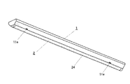
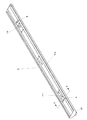
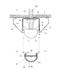
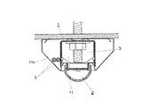
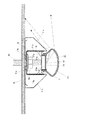
図1乃至図4において、天井面へ設置される天井直付けタイプの照明器具が示されており、この照明器具は、逆富士型をなしていて、横長であって長尺状をなす器具本体1と、この器具本体1に配設された光源部2及び点灯装置3と、光源部2を器具本体1に取付けて保持する係止部材4とを備えている。
In FIG. 1 to FIG. 4, a direct ceiling mounted type luminaire installed on a ceiling surface is shown, and this luminaire has a reverse Fuji type, and is a horizontally long and elongated appliance
図6及び図7の参照を加えて示すように、器具本体1は、亜鉛めっき鋼板を折曲して形成され、長手方向に沿って略中央部に収容凹部11が形成されている。収容凹部11は、天板部11aと、この天板部11aの両側から前面側に直角に垂下するように折曲されて形成された側壁11bとから構成されている。また、収容凹部11の開口部側であって幅方向の両側、すなわち、側壁11bの前面側の両側は、側面視、略V字状に折曲されて収容凹部11に沿って側板部11cが形成されている。したがって、側板部11cは、側面形状が背面方向へ拡がる傾斜面を備えている。
As shown additionally with reference to FIGS. 6 and 7, the
この収容凹部11及び側板部11cは板材を折曲して一体的に形成されており、少なくともこれらの前面側の表面は、光の反射率が高くなるように白色の塗装が施されている。したがって、側板部11cの傾斜面における表面は、反射面をなしていて、側板部11cは、反射板として機能するようになっている。
The housing recess 11 and the
収容凹部11の側板部11cにおける長手方向の両端部には、一対の係止爪通過孔11dが形成されている。この係止爪通過孔11dには、後述する係止部材4の係止爪4aが配置されるようになっている。また、この一対の係止爪通過孔11dと対向するように側板部11cには、解除孔11eが形成されている。この解除孔11eは、後述するように係止部材4の係止爪4aを解除操作するために用いられる。
A pair of locking
また、主として図2及び図6に示すように、器具本体1の背面側、すなわち、天板部11aの両端側には、一対の取付穴11fが形成されている。この取付穴11fには、天井の構造体に設けられた一対の取付ボルトBtが外面側から貫通し、器具本体1が天井面に設置されるようになっている。なお、取付穴11fの周囲には、取付穴11fを補強するために、背面側へドーム状に突出する補強部11gが形成されている。さらに、器具本体1の長手方向の両端には、略逆台形状の端板12が取付けられている。
Moreover, as shown mainly in FIG.2 and FIG.6, a pair of
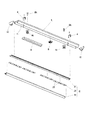
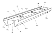
光源部2は、取付部材21と、複数の発光素子22が実装された基板23と、カバー部材24とを備えている。
The
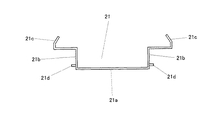
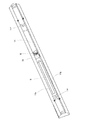
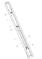
図8及び図9の参照を加えて示すように、取付部材21は、器具本体1と同様に、横長であって長尺状に形成されており、長手方向に沿って平坦な取付面21aと、この取付面21aの両側から背面方向へ直角に立ち上がった第1の側壁21bと、この第1の側壁21bから水平方向に延出し、さらに背面方向に向かって内側に傾斜状に立ち上がった第2の側壁21cとを有している。また、第1の側壁21bにおける取付面21a側には、複数の切起し片21dが略等間隔に幅方向の外側に突出して形成されている。
As shown with reference to FIG. 8 and FIG. 9, the
取付部材21には、亜鉛めっき鋼板やアルミニウムの板材等の熱伝導が良好な材料が用いられている。
For the
基板23は、略長方形状に形成されており、複数、すなわち、4枚の基板23が直線状に並べられて取付部材21の取付面21aにねじ止め等によって、その裏面側が取付面21aに密着するように取付けられている。この基板23の表面側には、複数の発光素子22が実装されている。
The
基板23は、絶縁材であるガラスエポキシ樹脂の平板からなり、表面側には銅箔で形成された配線パターンが施されている。また、適宜レジスト層が施されるようになっている。なお、基板23の材料は、絶縁材とする場合には、セラミックス材料又は合成樹脂材料を適用できる。さらに、金属製とする場合は、アルミニウム等の熱伝導性が良好で放熱性に優れた材料を適用するのが好ましい。
The
発光素子22は、LEDであり、表面実装型のLEDパッケージである。概略的にはセラミックスで形成された本体に配設されたLEDチップと、このLEDチップを封止するエポキシ系樹脂やシリコーン樹脂等のモールド用の透光性樹脂とから構成されている。
The
LEDチップは、青色光を発光する青色のLEDチップである。透光性樹脂には、蛍光体が混入されており、白色光を出射できるようにするために、青色の光とは補色の関係にある黄色系の光を放射する黄色蛍光体が使用されている。 The LED chip is a blue LED chip that emits blue light. In the translucent resin, a phosphor is mixed, and in order to allow white light to be emitted, a yellow phosphor that emits yellow-based light having a complementary color relationship with blue light is used. There is.
なお、LEDは、LEDチップを直接基板23に実装するようにしてもよく、また、砲弾型のLEDを実装するようにしてもよく、実装方式や形式は、格別限定されるものではない。
In the LED, the LED chip may be mounted directly on the
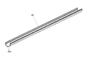
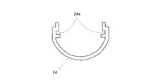
図10及び図11の参照を加えて示すように、カバー部材24は、アクリルやポリカーボネート等の透光性の材料から作られており、長尺状で半円筒状に形成されている。そして、カバー部材24の開放端部側には、長手方向に沿って一対の嵌合部としての嵌合溝24aが形成されている。また、カバー部材24は、フロスト処理が施されて発光素子22から出射される光を拡散する機能を有するようになっている。なお、カバー部材24に適宜拡散材を混入させて光の拡散性をもたせるようにしてもよい。
As shown additionally with reference to FIGS. 10 and 11, the
このように構成されたカバー部材24は、複数の発光素子22が実装された基板23を覆うように取付部材21に取付けられている。具体的には、図4に示すように、カバー部材24の一対の嵌合溝24aに取付部材21の切起し片21dがスライドして嵌合し、取付けられるようになっている。
The
以上のように、光源部2は、取付部材21と、複数の発光素子22が実装された基板23と、カバー部材24とが組合わされて一体化されて構成されている。
As described above, in the
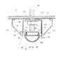
また、点灯装置3が器具本体1の収容凹部11における天板部11aの内側に取付けられている。点灯装置3は、箱状のケース内に回路基板及びこの基板に実装された回路部品を収容して構成されており、商用交流電源ACに接続されていて、この交流電源ACを受けて直流出力を生成するものである。点灯装置3は、例えば、全波整流回路の出力端子間に平滑コンデンサを接続し、この平滑コンデンサに直流電圧変換回路及び電流検出手段を接続して構成されている。したがって、点灯装置3は、基板23を介して発光素子22に接続されており、その直流出力を発光素子22に供給し、発光素子22を点灯制御するようになっている。
In addition, the
点灯装置3は、図4及び図14に示すように、そのケースの両側壁が収容凹部11の側壁11bに隙間なく接触するように配置されている。このため、点灯装置3は器具本体1を補強する役目を果たしている。なお、ここで、隙間なくとは、点灯装置3の側壁と収容凹部11の側壁11bとが全面的に接触している必要はなく、補強効果との関係で把握されるものであり、僅かな隙間の存在は許容されるものである。さらに、点灯装置3は、前記一方の取付穴11fの近傍に配置されている。
As shown in FIGS. 4 and 14, the
また、収容凹部11における天板部11aの内側には、端子台5が取付けられている。この端子台5には、電源線や送り線、調光信号線が接続されるようになっている。
Further, a
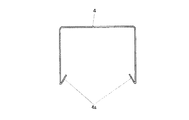
係止部材4は、図12及び図13の参照を加えて示すように、ステンレス材料等のばね材によって略コ字状に折曲して形成されている。また、係止部材4の両端には、係止部としての係止爪4aが内側に折曲して形成されている。この係止部材4は、図2乃至図4に示すように、器具本体1の収容凹部11の両端部側に外側から重合するように一対取付けられる。より詳しくは、図4に示すように、係止爪4aが収容凹部11の係止爪通過孔11dを通って配置され、収容凹部11の外側にねじ等の固定手段(図3参照)によって取付けられるようになっている。
The locking
このように構成された係止部材4には、図5に示すように、光源部2が取付けられる。つまり、収容凹部11の開口部側を覆うように光源部2が配設される。
As shown in FIG. 5, the
光源部2を器具本体1に対して図示矢印方向に移動すると、取付部材21の傾斜状の第2の側壁21cが係止部材4の係止爪4aに当接する。この状態からさらに光源部2の移動を進め、係止爪4aの弾性に抗して収容凹部11に押し込むようにすることにより、係止爪4aが第2の側壁21cによって外側に弾性変形し、光源部2が収容凹部11内へ移動する。そして、第2の側壁21cが所定量収容凹部11内へ入ると、係止爪4aの弾性変形が解かれ、取付部材21が係止爪4aによって所定位置に係合保持される(図4参照)。
When the
この場合、第2の側壁21cは、傾斜状に形成されているので、係止爪4aとの関係において、光源部2の取付けを円滑に行うことができる。
In this case, since the
この状態では、取付部材21の第2の側壁21cは、収容凹部11の側壁11bに面接触するようになっており、取付部材21と器具本体1とは、熱的に結合されるようになる。また、係止部材4は、器具本体1の収容凹部11の外側から重合するように取付けられているので、例え、ねじ等の固定手段が外れたとしても、光源部2が落下するのを防止でき、安全性を確保することができる。仮に、係止部材4を収容凹部11の内側に固定手段によって取付けた場合には、固定手段が外れると、光源部2が係止部材4とともに落下してしまう危険性が生じる。
In this state, the
上記のように構成された照明器具の天井面Cへの設置状態について、主として図4及び図5を参照して説明する。 The installation state of the lighting apparatus configured as described above on the ceiling surface C will be described mainly with reference to FIGS. 4 and 5.
まず、設置にあたっては、図5に示すように、天井の構造体に設けられた一対の取付ボルトBtを外面側から器具本体1の天板部11aの取付穴11fに通し、この取付ボルトBtに天板部11aの内面側からワッシャを介してナットNtを締め付ける。これにより、天板部11aの外面側の補強部11g及び側板部11cの背面側一端部が天井面Cに密着して器具本体1は、天井面Cに設置される。この場合、図15に示すように、取付ボルトBtが通り、ナットNtによって締め付けられる取付穴11f(図示上、左側)は、点灯装置3が配置される部位の近傍に形成されているので、上述の補強効果でその締め付け力によって器具本体1が変形するのを抑制することができる。
First, in the installation, as shown in FIG. 5, a pair of mounting bolts Bt provided on the structure of the ceiling are passed from the outer surface side through the mounting
続いて、光源部2を器具本体1に取付ける。この場合、図4に示すように、収容凹部11には、所定の収容スペースが確保されるようになっている。このため、収容凹部11に点灯装置3や端子台5等を配置することが可能となり、また、光源部2を器具本体1に取付けることによって、点灯装置3、端子台5や配線関係部材が光源部2でカバーされ、外観上見え難くなるので、格別な部材を設けることなく外観性を良好なものとすることが可能となる。
Subsequently, the
また、収納凹部11を有する器具本体1には、反射板として供される側板部11cが一体的に形成されているので、部品点数を少なくでき、施工作業の省力化を図ることができる。
Moreover, since the
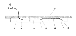
次に、図16に示すように、上記照明器具は、天井面Cへ複数台直列的に配置される場合がある。この場合、各照明器具を送り線6(電源線)で連続的に接続する必要がある。本実施形態の照明器具では、図15に示すように、端子台5の近傍であって収容凹部11の側壁11bには、送り線通過孔6aが形成されている。したがって、送り線6を端子台5から送り線通過孔6aを通して導出させて、図17に示すように、器具本体1の収容凹部11の外側と側板部11cとで形成される空間を通過させて次段の照明器具に接続することができる。これにより、前記空間を有効に利用してまとまりよく送り線6を配線することができる。
Next, as illustrated in FIG. 16, a plurality of the lighting devices may be arranged in series on the ceiling surface C. In this case, it is necessary to connect each lighting fixture continuously by the feed line 6 (power supply line). In the lighting apparatus of the present embodiment, as shown in FIG. 15, a feed line passage hole 6 a is formed in the vicinity of the
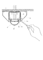
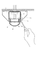
次に、図18に示すように、メンテナンス等により器具本体1から光源部2を取外すため、係止部材4を解除する動作について説明する。例えば、ドライバー等の工具用い、ドライバーの先端を側板部11cに形成された解除孔11eに挿入する。次いで、係止部材4の係止爪4aをドライバーによって図示矢印方向に変形させて係止爪通過孔11dから外す。すると、係止爪4aの係合が解かれるので(他方の係止部材4の係止爪4aの係合も解除する)、光源部2を下方に引っ張ることにより光源部2を取外すことができる。このように解除孔11eが形成されているので光源部2の取外しを容易に行うことができる。
Next, as shown in FIG. 18, an operation of releasing the locking
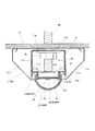
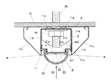
図4に代表して示すように、照明器具の設置状態において、点灯装置3に電力が供給されると、基板23を介して発光素子22に通電され、各発光素子22が点灯する。発光素子22から出射された光は、拡散性を有する透光性のカバー部材24を透過して拡散され、主として下方に放射されるとともに、一部の光は、側板部11cの表面で反射され、また、天井面Cに照射される。これにより、照明の明るさ感を増すことができる。また、各発光素子22から発生する熱は、基板23裏面側から取付部材21に伝導され、さらに取付部材21の第2の側壁21cから器具本体1へ伝導されて放熱される。これによって、発光素子22の温度上昇を抑制することができる。
As representatively shown in FIG. 4, when power is supplied to the
以上のように本実施形態によれば、収容凹部11を有する器具本体1には、側板部11cが一体的に形成されているので、部品点数を少なくでき、施工作業の省力化を図ることができる。また、収容凹部11には、所定の収容スペースが確保されるようになっているので点灯装置3を効率的に配置することが可能となり、さらに、光源部2を器具本体1に取付けることによって、点灯装置3等の部品が光源部2でカバーされ、外観性を良好なものとすることができる。
As described above, according to the present embodiment, since the
また、点灯装置3は、収容凹部11に隙間なく配置されているため、器具本体1の補強を図ることができる。
Moreover, since the
次に、本発明の第2の実施形態に係る照明器具について図19及び図20を参照して説明する。なお、第1の実施形態と同一又は相当部分には同一符号を付し重複した説明は省略する。 Next, a lighting apparatus according to a second embodiment of the present invention will be described with reference to FIGS. 19 and 20. FIG. The same or corresponding portions as in the first embodiment are denoted by the same reference numerals, and redundant description will be omitted.
(実施例1)図19に示すように、本実施例では、発光素子22の実装位置を収容凹部11の開口部側端部より突出させるようにしたものである。すなわち、収容凹部11の開口部側端部の間を結ぶ水平線を基準線Aとした場合、この基準線Aより前面側に発光素子22が突出するように配置したものである。これにより、発光素子22から出射された光は、拡散性を有する透光性のカバー部材24を透過して拡散され、下方に放射されるとともに、側板部11cや天井面Cに照射される光の量を増加させることが可能となり、明るさ感を増すことができる。
また、本実施例では、カバー部材24は、側板部11cの背面方向へ拡がる傾斜面の外形線の延長線Bより外側に突出するようになっている。したがって、発光素子22から出射された光は、拡散性を有する透光性のカバー部材24を透過して拡散され、側板部11cや天井面Cに照射される光の量を一層増加させることが可能となり、明るさ感を増すことができる。
Further, in the present embodiment, the
なお、本実施例においては、基準線Aより前面側に発光素子22が突出するように配置する構成又は延長線Bより外側にカバー部材24が突出する構成のいずれか一方を選択するようにしてもよい。
In the present embodiment, one of the configuration in which the
(実施例2)図20に示すように、本実施例では、カバー部材24の内面側に山形の凸部24bを形成したものである。この凸部24bによって発光素子22から出射された光の拡散性を促進することができ、側板部11cや天井面Cに照射される光の量を増加させることが可能となる。
(Embodiment 2) As shown in FIG. 20, in this embodiment, a mountain-shaped
次に、本発明の第3の実施形態に係る照明器具について図21を参照して説明する。なお、第1の実施形態と同一又は相当部分には同一符号を付し重複した説明は省略する。 Next, a lighting apparatus according to a third embodiment of the present invention will be described with reference to FIG. The same or corresponding portions as in the first embodiment are denoted by the same reference numerals, and redundant description will be omitted.
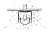
本実施形態では、カバー部材24を前面側へ膨出させるように形成し、側板部11cの背面方向へ拡がる傾斜面より外側に突出する量を多くするようにしたものである。したがって、この構成により、発光素子22から出射された光は、拡散性を有する透光性のカバー部材24を透過して拡散され、特に、カバー部材24の膨出部分において拡散された光は、側板部11cや天井面Cに向かい、これらに照射されるので、照明の明るさ感を増すことが可能となる。
In the present embodiment, the
次に、本発明の第4の実施形態に係る照明器具について図22及び図23を参照して説明する。なお、第1の実施形態と同一又は相当部分には同一符号を付し重複した説明は省略する。 Next, a lighting apparatus according to a fourth embodiment of the present invention will be described with reference to FIGS. The same or corresponding portions as in the first embodiment are denoted by the same reference numerals, and redundant description will be omitted.
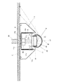
本実施形態では、第1の実施形態とは、光源部2の取付構造が異なる形態を示している。図22に示すように、取付部材21において、一方の第2の側壁21cと対向する他方側には、収容凹部11の側壁11bに形成された孔11hを通って水平方向に延出し、先端側に引掛け部21fを有する係止壁21eが形成されている。
In the present embodiment, the attachment structure of the
このような構成によれば、図23に示すように、器具本体1に光源部2を取付ける場合、係止壁21eの引掛け部21fを孔11hに引掛けて、光源部2を吊り下げ状態にして、引掛け部21fを支点として光源部2を図示矢印方向に回動するように操作することにより、光源部2を取付けることができる。
According to such a configuration, as shown in FIG. 23, when attaching the
したがって、器具本体1に光源部2を取付けるに際し、光源部2の落下を防止できるとともに、取付作業が容易となる効果が期待できる。
Therefore, when attaching the
次に、本発明の第5の実施形態に係る照明器具について図24及び図25を参照して説明する。なお、第1の実施形態と同一又は相当部分には同一符号を付し重複した説明は省略する。 Next, a lighting apparatus according to a fifth embodiment of the present invention will be described with reference to FIGS. 24 and 25. FIG. The same or corresponding portions as in the first embodiment are denoted by the same reference numerals, and redundant description will be omitted.
本実施形態は、器具本体1に対し、光源部2の前面側、背面側方向への突出量を変更できるようにしたものである。これによって、遮光角を調整することができる。
In the present embodiment, the amount of protrusion of the
係止部材4には、前面側、背面側方向に位置の異なる2段階の係止爪4a1、4a2が設けられている。光源部2は、前面背面方向に可動でき、取付部材21が係止爪4a1、4a2によって所定位置に係合保持されるようになっている。
The locking
図24に示す状態は、前面側の係止爪4a1に取付部材21が係合されている状態であり、遮光角は小さく設定される。この状態から光源部2を背面側へ移動して背面側の係止爪4a2に取付部材21を係合することにより遮光角を大きく設定することができる。
The state shown in FIG. 24 is a state in which the mounting
したがって、本実施形態によれば、照明器具の設置環境に応じて遮光角の調整が可能となる。なお、光源部2の突出量の変更は、2段階のみならず多段的に変更できるようにしてもよく、さらには、任意に変更できるようにしてもよい。これによって、遮光角の調整範囲を広げることができる。
Therefore, according to the present embodiment, the light shielding angle can be adjusted according to the installation environment of the lighting apparatus. The amount of protrusion of the
次に、本発明の第6の実施形態に係る照明器具について図26を参照して説明する。なお、第1の実施形態と同一又は相当部分には同一符号を付し重複した説明は省略する。 Next, a lighting apparatus according to a sixth embodiment of the present invention will be described with reference to FIG. The same or corresponding portions as in the first embodiment are denoted by the same reference numerals, and redundant description will be omitted.
本実施形態は、収容凹部11の開口部側を覆うように光源部2が配設されるが、光源部2のカバー部材24が収容凹部11の開口部側を隙間がないように覆い配置される構成となっている。
In the present embodiment, the
したがって、収容凹部11の開口部側において、カバー部材24と収容凹部11との隙間による光学的な暗部が生じるのを抑制することが可能となる。また、この場合、メンテナンス等により器具本体1から光源部2を取外すため、係止部材4を解除する際には、収容凹部11の開口部側には隙間がないので、側板部11cに形成された解除孔11eにドライバー等の工具を挿入して解除するのが不可欠的操作となる。
Therefore, it is possible to suppress the occurrence of an optical dark portion due to the gap between the
なお、本発明は、上記実施形態の構成に限定されることなく、発明の要旨を逸脱しない範囲で種々の変形が可能である。例えば、発光素子は、LEDや有機EL等の固体発光素子が適用できる。 The present invention is not limited to the configuration of the above embodiment, and various modifications can be made without departing from the scope of the invention. For example, as the light emitting element, a solid light emitting element such as an LED or an organic EL can be applied.
また、発光素子を基板に実装する場合、発光素子を表面実装方式で実装する場合や発光素子を直接基板に実装する場合がある。発光素子の実装個数は、特段限定されるものではない。 When the light emitting element is mounted on the substrate, the light emitting element may be mounted by a surface mounting method or the light emitting element may be mounted directly on the substrate. The number of light emitting elements mounted is not particularly limited.
また、器具本体の側板部は、反射板としての機能を有していることが好ましいが、必ずしもこの機能を有していなくてもよい。 Moreover, although it is preferable that the side plate part of an instrument main body has a function as a reflecting plate, it does not necessarily need to have this function.
1・・・器具本体、2・・・光源部、3・・・点灯装置、4・・・係止部材、4a・・・係止部としての係止爪、11・・・収容凹部、11b・・・側壁、11c・・・側板部、21・・・取付部材、21a・・・取付面、21b・・・の側壁、22・・・発光素子(LED)、23・・・基板、24・・・カバー部材、24a・・・嵌合部としての嵌合溝
DESCRIPTION OF
Claims (2)
前記長手方向に沿って平坦な取付面を有する金属製の取付部材と;
前記取付部材の取付面に配設され、複数の発光素子が実装された基板と;
前記基板の前面側を覆うように前記取付部材が取付けられるカバー部材と;
を具備し、
前記光源部は、前記器具本体の照射方向側に配置され、前記器具本体の前記開口の短手方向幅よりも前記カバー部材の短手方向の最大幅が大きく形成されており、前記カバー部材の前記最大幅の部分が前記器具本体の前記開口よりも前記照射方向側に位置することを特徴とする光源部。 A light source unit disposed from the opening side of an instrument body having an opening formed along a longitudinal direction,
A metal mounting member having a flat mounting surface along said longitudinal direction;
A substrate disposed on the attachment surface of the attachment member and on which a plurality of light emitting elements are mounted;
A cover member is-attached prior Quito to cover the front side is attached in front Kimoto plate;
Equipped with
The light source unit is disposed on the irradiation direction side of the device body, and the maximum width in the width direction of the cover member is formed larger than the width direction width of the opening of the device body. light source unit characterized that you positioned in the irradiation direction side than the portion of the maximum width the opening of the instrument body.
前記長手方向に交差する断面において、前記器具本体の前記第1傾斜面に沿って延びる直線と、前記カバー部材において前記最大幅の部分から前記開口側に向けて形成される第2傾斜面とが交差するように取り付けられる請求項1記載の光源部と;
を具備していることを特徴とする照明器具。 An instrument body having a pair of side plate portions having a first inclined surface formed with an opening along a longitudinal direction and extending in a direction away from each other in the lateral direction of the opening ;
In a cross section intersecting the longitudinal direction, a straight line extending along the first inclined surface of the device body, and a second inclined surface formed from the portion of the maximum width of the cover member toward the opening side The light source unit according to claim 1, which is mounted to cross each other;
A luminaire characterized by comprising.
Priority Applications (1)
| Application Number | Priority Date | Filing Date | Title |
|---|---|---|---|
| JP2017118214A JP6424924B2 (en) | 2017-06-16 | 2017-06-16 | Light source unit and lighting apparatus |
Applications Claiming Priority (1)
| Application Number | Priority Date | Filing Date | Title |
|---|---|---|---|
| JP2017118214A JP6424924B2 (en) | 2017-06-16 | 2017-06-16 | Light source unit and lighting apparatus |
Related Parent Applications (1)
| Application Number | Title | Priority Date | Filing Date |
|---|---|---|---|
| JP2016036057A Division JP6160846B2 (en) | 2016-02-26 | 2016-02-26 | lighting equipment |
Publications (2)
| Publication Number | Publication Date |
|---|---|
| JP2017188474A JP2017188474A (en) | 2017-10-12 |
| JP6424924B2 true JP6424924B2 (en) | 2018-11-21 |
Family
ID=60045054
Family Applications (1)
| Application Number | Title | Priority Date | Filing Date |
|---|---|---|---|
| JP2017118214A Active JP6424924B2 (en) | 2017-06-16 | 2017-06-16 | Light source unit and lighting apparatus |
Country Status (1)
| Country | Link |
|---|---|
| JP (1) | JP6424924B2 (en) |
Families Citing this family (1)
| Publication number | Priority date | Publication date | Assignee | Title |
|---|---|---|---|---|
| JP7167734B2 (en) * | 2019-01-23 | 2022-11-09 | 東芝ライテック株式会社 | lighting equipment |
Family Cites Families (4)
| Publication number | Priority date | Publication date | Assignee | Title |
|---|---|---|---|---|
| EP1711739A4 (en) * | 2004-01-28 | 2008-07-23 | Tir Technology Lp | LUMINAIRE DIRECTLY VISIBLE |
| TWM345942U (en) * | 2008-05-16 | 2008-12-01 | Ledtech Electronics Corp | Customized assembling lighting module |
| JP2010108844A (en) * | 2008-10-31 | 2010-05-13 | Ledtech Electronics Corp | Assembly type light-emitting module |
| JP4365884B1 (en) * | 2009-02-09 | 2009-11-18 | 株式会社ケノス | LED board mounting device |
-
2017
- 2017-06-16 JP JP2017118214A patent/JP6424924B2/en active Active
Also Published As
| Publication number | Publication date |
|---|---|
| JP2017188474A (en) | 2017-10-12 |
Similar Documents
| Publication | Publication Date | Title |
|---|---|---|
| JP5652015B2 (en) | lighting equipment | |
| KR101369422B1 (en) | Light emitting diode lighting lamp | |
| JP6674642B2 (en) | lighting equipment | |
| JP2013037852A (en) | Lighting fixture | |
| JP5892355B2 (en) | lighting equipment | |
| JP5704420B2 (en) | lighting equipment | |
| CN102404913A (en) | lighting equipment | |
| JP5294044B2 (en) | lighting equipment | |
| JP6238144B2 (en) | lighting equipment | |
| JP6160846B2 (en) | lighting equipment | |
| JP6424924B2 (en) | Light source unit and lighting apparatus | |
| JP5320563B2 (en) | lighting equipment | |
| JP2016136536A (en) | lighting equipment | |
| JP6137369B2 (en) | lighting equipment | |
| JP6160883B2 (en) | lighting equipment | |
| KR101961936B1 (en) | Light emitting diode lamp substitute for fluorescent light | |
| JP7377444B2 (en) | lighting equipment | |
| JP6948022B2 (en) | lighting equipment | |
| JP5888624B2 (en) | lighting equipment | |
| JP2012146441A (en) | Lighting fixture | |
| JP5790932B2 (en) | lighting equipment | |
| JP2012134034A (en) | Led lighting system | |
| JP6241563B2 (en) | lighting equipment | |
| JP6274458B2 (en) | lighting equipment | |
| JP6525071B2 (en) | lighting equipment |
Legal Events
| Date | Code | Title | Description |
|---|---|---|---|
| A977 | Report on retrieval |
Free format text: JAPANESE INTERMEDIATE CODE: A971007 Effective date: 20180322 |
|
| A131 | Notification of reasons for refusal |
Free format text: JAPANESE INTERMEDIATE CODE: A131 Effective date: 20180329 |
|
| A521 | Written amendment |
Free format text: JAPANESE INTERMEDIATE CODE: A523 Effective date: 20180528 |
|
| RD02 | Notification of acceptance of power of attorney |
Free format text: JAPANESE INTERMEDIATE CODE: A7422 Effective date: 20180528 |
|
| TRDD | Decision of grant or rejection written | ||
| A01 | Written decision to grant a patent or to grant a registration (utility model) |
Free format text: JAPANESE INTERMEDIATE CODE: A01 Effective date: 20180925 |
|
| A61 | First payment of annual fees (during grant procedure) |
Free format text: JAPANESE INTERMEDIATE CODE: A61 Effective date: 20181008 |
|
| R151 | Written notification of patent or utility model registration |
Ref document number: 6424924 Country of ref document: JP Free format text: JAPANESE INTERMEDIATE CODE: R151 |