JP2012146441A - Lighting fixture - Google Patents
Lighting fixture Download PDFInfo
- Publication number
- JP2012146441A JP2012146441A JP2011002937A JP2011002937A JP2012146441A JP 2012146441 A JP2012146441 A JP 2012146441A JP 2011002937 A JP2011002937 A JP 2011002937A JP 2011002937 A JP2011002937 A JP 2011002937A JP 2012146441 A JP2012146441 A JP 2012146441A
- Authority
- JP
- Japan
- Prior art keywords
- light
- light emitting
- main body
- substrate
- emitting element
- Prior art date
- Legal status (The legal status is an assumption and is not a legal conclusion. Google has not performed a legal analysis and makes no representation as to the accuracy of the status listed.)
- Pending
Links
Images


Abstract
Description
本発明の実施形態は、光源としてLED等の発光素子を用いた照明器具に関する。 Embodiments described herein relate generally to a lighting fixture using a light emitting element such as an LED as a light source.
一般住宅用の照明器具においては、主光源に環状の蛍光ランプを用い、この環状の蛍光ランプの下方側を覆うようにカバー部材(セード)を設けて、外観形状を丸形に構成するものが普及している。 In general residential lighting fixtures, an annular fluorescent lamp is used as a main light source, and a cover member (sade) is provided so as to cover the lower side of the annular fluorescent lamp, and the external shape is configured in a round shape. It is popular.
一方、近時、LED等の発光素子の高出力化、高効率化及び普及化に伴い、光源として発光素子を用いて長寿命化が期待できる照明器具が開発されている。このように発光素子を用いて長寿命化が期待できる照明器具にあっては、メンテナンスために光源を交換したり、内部の掃除をしたりする必要性が少ないため、光源としての発光素子を下方側から覆うカバー部材を本体側にねじ等の固定手段によって固定することが行われている。 On the other hand, recently, with the increase in output, efficiency, and widespread use of light emitting elements such as LEDs, lighting fixtures that can be expected to have a long lifetime using light emitting elements as light sources have been developed. In such a lighting fixture that can be expected to have a long life using a light emitting element, it is not necessary to replace the light source for maintenance or to clean the inside. The cover member covering from the side is fixed to the main body side by a fixing means such as a screw.
しかしながら、上記照明器具の場合、カバー部材と本体等の僅かな隙間から虫等が本体内部に侵入してしまう場合がある。このような場合、内部の掃除を行うためには、カバー部材をねじ等の固定手段を取外して分解しなければならない。この作業は、使用者にとって時間と労力を費やす面倒な作業となる。 However, in the case of the luminaire described above, insects or the like may enter the main body through a slight gap between the cover member and the main body. In such a case, in order to clean the inside, the cover member must be disassembled by removing fixing means such as screws. This work is a troublesome work that consumes time and labor for the user.
本発明は、上記課題に鑑みなされたもので、発光素子を光源とする光源部を備えたものにおいて、内部の掃除が容易となる照明器具を提供することを目的とする。 The present invention has been made in view of the above problems, and an object of the present invention is to provide an illuminating device that can be easily cleaned in the interior provided with a light source unit that uses a light emitting element as a light source.
本発明の実施形態による照明器具は、器具取付面に設置された配線器具に対向する取付部を有する本体を備えている。また、この本体に配設され、発光素子を光源とする光源部と、前記本体の外周部に着脱可能に取付けられるとともに、前記発光素子を所定の離間距離をおいて覆う透光性のカバー部材とを備えている。 The lighting fixture by embodiment of this invention is equipped with the main body which has an attaching part facing the wiring fixture installed in the fixture attachment surface. Further, a light source part that is disposed in the main body and has a light emitting element as a light source, and a translucent cover member that is detachably attached to the outer peripheral part of the main body and covers the light emitting element with a predetermined separation distance. And.
本発明の実施形態によれば、光源として発光素子を用いたものにおいて、本体に対してカバー部材を着脱可能に取付けるようにしたので、内部の掃除が容易となる照明器具を提供することができる。 According to the embodiment of the present invention, since the cover member is detachably attached to the main body using the light emitting element as the light source, it is possible to provide a lighting apparatus that facilitates internal cleaning. .
以下、本発明の実施形態について図1乃至図8を参照して説明する。各図においてリード線等による配線接続関係は省略して示している場合がある。なお、同一部分には同一符号を付し、重複した説明は省略する。 Hereinafter, embodiments of the present invention will be described with reference to FIGS. 1 to 8. In each drawing, the wiring connection relationship using lead wires or the like may be omitted. In addition, the same code | symbol is attached | subjected to the same part and the overlapping description is abbreviate | omitted.
本実施形態の照明器具は、器具取付面に設置された配線器具としての引掛けシーリングボディに取付けられて使用される一般住宅用のものであり、基板に実装された複数の発光素子を有する光源部から放射される光によって室内の照明を行うものである。 The lighting apparatus of the present embodiment is for a general house that is used by being attached to a hanging sealing body as a wiring apparatus installed on the apparatus mounting surface, and has a plurality of light emitting elements mounted on a substrate. The room is illuminated by light emitted from the section.
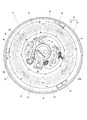
図1乃至図4において、照明器具は、本体1と、光源部2と、拡散部材3と、点灯装置4と、点灯装置カバー5と、取付部6と、カバー部材7とを備えている。また、器具取付面としての天井面Cに設置された引掛けシーリングボディCbに電気的かつ機械的に接続されるアダプタAを備えている。このような照明器具は、丸形の円形状の外観に形成され、前面側を光の照射面とし、背面側を天井面Cへの取付面としている。
1 to 4, the lighting fixture includes a
図2乃至図5に示すように、本体1は、冷間圧延鋼板等の金属材料の平板から円形状に形成されたシャーシであり、略中央部に、後述する取付部6を配設するための円形状の開口11が形成されている。また、光源部2が取付けられる内面側の平坦部12の外周側には、背面側に向かう段差部13が形成されて樋状の凹部14が形成されている。そして、前記段差部13には、カバー部材7が着脱可能に取付けられるカバー受部材が配置されている。カバー受部材は、より詳しくは、カバー受金具75であり、段差部13によって形成される凹部14に配置されるようになっている。さらに、本体1の背面側には、弾性部材15が設けられている。
As shown in FIGS. 2 to 5, the
光源部2は、図6の参照を加えて説明するように、基板21と、この基板21に実装された複数の発光素子22とを備えている(図2においては発光素子22の図示を省略している)。基板21は、所定の幅寸法を有した円弧状の4枚の基板21が繋ぎ合わされるように配設されて全体として略サークル状に形成されている。つまり、全体として略サークル状に形成された基板21は、4枚の分割された基板21から構成されている。
The
このように分割された基板21を用いることにより、基板21の分割部で熱的収縮を吸収して基板21の変形を抑制することができる。なお、複数に分割された基板21を用いることが好ましいが、略サークル状に一体的に形成された一枚の基板を用いるようにしてもよい。
By using the
基板21は、絶縁材であるガラスエポキシ樹脂(FR−4)の平板からなり、表面側には銅箔によって配線パターンが形成されている。また、配線パターンの上、つまり、基板21の表面には反射層として作用する白色のレジスト層が施されている。なお、基板21の材料は、絶縁材とする場合には、セラミックス材料又は合成樹脂材料を適用できる。さらに、金属製とする場合は、アルミニウム等の熱伝導性が良好で放熱性に優れたべース板の一面に絶縁層が積層された金属製のべース基板を適用できる。
The board |
発光素子22は、LEDであり、表面実装型のLEDパッケージである。このLEDパッケージが複数個サークル状の基板21の周方向に沿って、つまり、取付部6を中心とする略円周上に複数列、本実施形態では、内周側及び外周側の2列に亘って実装されている。また、LEDパケージには、発光色が昼白色Nのものと電球色Lのものとが用いられており、これらが交互に並べられていて、各列の隣接する発光素子22は略等間隔を空けて配設されている。この昼白色と電球色のLEDパッケージに流れる電流等を調整することにより調色が可能となっている。
The
なお、特定の基板21a(図3中、右側、図6中、右上側)には、常夜灯用の発光素子22aが実装されている。この発光素子22aには、サークル状に実装された主光源における電球色のものと同じ仕様のLEDパッケージが用いられている。これにより部材の共通化が図られている。
In addition, the
なお、発光素子22は、必ずしも複数列に実装する必要はない。例えば、周方向に沿って1列に実装するようにしてもよい。所望する出力に応じて発光素子22の列数や個数を適宜設定することができる。
The
LEDパッケージは、概略的にはセラミックスや合成樹脂で形成された本体に配設されたLEDチップと、このLEDチップを封止するエポキシ系樹脂やシリコーン樹脂等のモールド用の透光性樹脂とから構成されている。LEDチップは、青色光を発光する青色のLEDチップである。透光性樹脂には、昼白色や電球色の光を出射できるようにするために蛍光体が混入されている。 The LED package is roughly composed of an LED chip disposed in a main body formed of ceramics or synthetic resin, and a translucent resin for molding such as epoxy resin or silicone resin that seals the LED chip. It is configured. The LED chip is a blue LED chip that emits blue light. The translucent resin is mixed with a phosphor so that daylight white or light bulb color light can be emitted.
なお、LEDは、LEDチップを直接基板21に実装するようにしてもよく、また、砲弾型のLEDを実装するようにしてもよく、実装方式や形式は、格別限定されるものではない。
In addition, LED may be made to mount an LED chip directly on the board |
拡散部材3は、レンズ部材であり、図7の参照を加えて説明するように、例えば、ポリカーボネートやアクリル樹脂等の絶縁性を有する透明合成樹脂からなり、前記発光素子22の配置に沿って略サークル状に一体的に形成されていて、発光素子22を含めて基板21の全面を覆うように配設されている。
The diffusing
また、レンズ部材は、図5及び図7に代表して示すように、略サークル状の内周側部分と外周側部分とに発光素子22に対向して円周方向に2条の山形であって、断面形状が一定の突条部31が連続して形成されている。この突条部31の内側には、U字状の溝32が円周方向に沿って連続して形成されている。したがって、U字状の溝32は、複数の発光素子22と対向して配置されるようになっており、複数の発光素子22は、U字状の溝32内に収められて覆われている状態となっている。
さらに、これら突条部31からは幅方向に延出する平坦部33が形成されており、これにより基板21の全面が覆われるようになっている。
Further, as representatively shown in FIGS. 5 and 7, the lens member has two chevron shapes in the circumferential direction facing the
Further, a
このように構成されたレンズ部材によれば、図5に示すように複数の発光素子22から出射された光は、突条部31によって、主として円周上の内周方向及び外周方向に拡散されて放射される。すなわち、発光素子22から出射された光は、発光素子22が配置されたところのサークル状の中心を原点とする半径方向へ主として拡散して放射されるようになる。
According to the lens member configured in this way, as shown in FIG. 5, the light emitted from the plurality of
したがって、レンズ部材によって複数の発光素子22から出射される光による照射光の均斉度を向上することが可能となる。さらに、各発光素子22の輝度による粒々感を抑制することができる。この場合、拡散による配光角度を120度〜160度程度に設定するのが望ましい。
また、拡散部材3には、平坦部33が形成されて基板21の全面を覆うようになっているので、充電部が拡散部材3によって覆われ保護される。
Therefore, it is possible to improve the uniformity of the irradiation light by the light emitted from the plurality of
Moreover, since the
なお、拡散部材3は、略サークル状に一体的に形成されていなくてもよい。例えば、分割された基板21に対応して、これらの基板21ごとに分割して形成するようにしてもよい。この場合には、一つの基板21に実装された複数の発光素子22ごとに連続して拡散部材3によって覆われるようになる。
また、拡散部材3は、レンズ部材に限らず、拡散シート等を適用するようにしてもよい。
Note that the diffusing
Further, the
上記のように構成された光源部2は、図4及び図5に代表して示すように、基板21が取付部6の周囲に位置して、発光素子22の実装面が前面側、すなわち、下方の照射方向に向けられて配設されている。また、基板21の裏面側が本体1の内面側の平坦部12に密着するように面接触して取付けられている。具体的には、基板21の前面側から拡散部材3が重ね合わされ、この拡散部材3を例えば、ねじS等の固定手段によって本体1に取付けることにより、基板21は、本体1と拡散部材3との間挟み込まれて押圧固定されるようになっている。つまり、1本のねじSによって基板21と拡散部材3とが共締めされている。
In the
したがって、基板21は、本体1と熱的に結合され、基板21からの熱が裏面側から本体1に伝導され放熱されるようになっている。なお、基板21と本体1との面接触は、基板21の全面が本体1に接触する場合に限らない。部分的な面接触であってもよい。
Accordingly, the
加えて、拡散部材3における平坦部33は、基板21の実装面側に密着するように面接触しているので、基板21の実装面側から熱が拡散部材3に伝わり、拡散部材3を経由して放熱することが可能となる。つまり、基板21の前面側からも放熱できるようになっている。
In addition, since the
点灯装置4は、図2乃至図4に示すように、回路基板41と、この回路基板41に実装された制御用IC、トランス、コンデンサ等の回路部品42とを備えている。回路基板41は、取付部6の周囲を囲むように略円弧状に形成されていて、アダプタA側が電気的に接続されて、アダプタAを介して商用交流電源に接続されている。したがって、点灯装置4は、この交流電源を受けて直流出力を生成し、リード線を介してその直流出力を発光素子22に供給し、発光素子22を点灯制御するようになっている。
このような点灯装置4は、取付部6と光源部2、すなわち、基板21との間に配設されている。
As shown in FIGS. 2 to 4, the
Such a
点灯装置カバー5は、図2及び図4に示すように、冷間圧延鋼板等の金属材料によって略短円筒状に形成され、点灯装置4を覆うように本体1に取付けられている。側壁51は、背面側に向かって拡開するように傾斜状をなしており、前面壁52には、取付部6と対応するように開口部53が形成されている。したがって、発光素子22から出射される一部の光は、側壁51によって前面側に反射され有効に利用されるようになる。また、この開口部53に周縁には背面側へ凹となる円弧状のガイド凹部54が形成されている。
As shown in FIGS. 2 and 4, the
取付部6は、略円筒状に形成されたアダプタガイドであり、このアダプタガイドの中央部には、アダプタAが挿通し、係合する係合口61が設けられている。このアダプタガイドは、本体1の中央部に形成された開口11に対応して配設されている。アダプタガイドの外周部には、この外周部から突出するように基台が形成されていて、この基台には赤外線リモコン信号受信部や照度センサ等の電気的補助部品62が配設されている。
The
なお、取付部6は、必ずしもアダプタガイド等と指称される部材である必要はない。例えば、本体1等に形成される開口であってもよく、要は、配線器具としての引掛けシーリングボディCbに対向し、アダプタAが係合される部材や部分を意味している。
Note that the
カバー部材7は、アクリル樹脂等の透光性を有し、乳白色を呈する拡散性を備えた材料から略円形状に形成されており、中央部には不透光性の円形状の化粧カバー71が取付けられている。また、この化粧カバー71には、前記電気的補助部品62と対向するように略三角形状の透光性を有する受光窓72が形成されている。さらに、カバー部材7の内面側の中央寄りには、内面方向に突出する突出ピン73が形成されている。
The
そして、カバー部材7は、光源部2を含めた本体1の前面側を覆うように本体1の外周縁部に着脱可能に取付けられるようになっている。具体的には、図8に示すように、カバー部材7を回動することによって、カバー部材7に設けられたカバー取付金具74を本体1の外周部の段差部13における凹部14に配設されたカバー受金具75に係合することにより取付けられる。また、カバー部材7を取外す場合には、カバー部材7を取付時とは反対方向に回動して、カバー取付金具74とカバー受金具75との係合を解くことにより、取外すことができる。
The
このようにカバー部材7が本体1に取付けられた状態においては、主として図4に示すように、カバー部材7の内面側は、点灯装置カバー5の前面壁52に面接触するようになる。したがって、点灯装置4等から発生する熱を点灯装置カバー5へ伝導し、さらにカバー部材7へ伝導させて放熱を促進することが可能となる。
Thus, in a state where the
また、拡散部材3とカバー部材7との間の距離は、20〜60mm、好ましくは30〜50mmに設定されている。これにより、発光素子22から出射される光が拡散され照射光の均斉度が良好となり、また、基板21の実装面側から拡散部材3に伝導された熱がカバー部材7を経由して効果的に放熱されるようになる。
The distance between the
ここで、カバー部材7は、回動させて本体1に取付けられるが、受光窓72の位置を電気的補助部品62と対向するように位置合わせをする必要がある。このため、本実施形態においては、詳細な説明は省略するが、カバー部材7側に形成された突出ピン73と点灯装置カバー5に形成されたガイド凹部54とによって位置規制手段が構成されている。この位置規制手段によって受光窓72が電気的補助部品62と対向して位置されるようになり、例えば、赤外線リモコン信号受信部が赤外線リモコン送信器からの制御信号を受信できるようになる。
Here, the
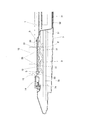
アダプタAは、天井面Cに設置された引掛けシーリングボディCbに、上面側に設けられた引掛刃によって電気的かつ機械的に接続されるもので略円筒状をなし、周壁の両側には一対の係止部A1が、内蔵されたスプリングによって常時外周側へ突出するように設けられている。この係止部A1は下面側に設けられたレバーを操作することにより没入するようになっている。また、このアダプタAからは、前記点灯装置4へ接続する電源コードが導出されていて、点灯装置4とコネクタを介して接続されるようになっている(図3参照)。
The adapter A is electrically and mechanically connected to a hooking sealing body Cb installed on the ceiling surface C by a hooking blade provided on the upper surface side, and has a substantially cylindrical shape. Is provided so that it always protrudes to the outer peripheral side by a built-in spring. The locking portion A1 is immersed by operating a lever provided on the lower surface side. Further, a power cord for connecting to the
次に、照明器具の天井面Cへの取付状態について図4を参照して説明する。まず、予め天井面Cに設置されている引掛けシーリングボディCbにアダプタAが電気的かつ機械的に接続されている。この状態から取付部6としてのアダプタガイドの係合口61をアダプタAに合わせながら、アダプタAの係止部A1がアダプタガイドの係合口61に確実に係合するまで器具本体を下方から手で押し上げて取付け操作を行う。そして、カバー部材7を本体1に取付ける。この取付完了状態が図4に示す状態であり、このとき、弾性部材15が天井面Cと本体1の背面側との間に密着状態で介在され、照明器具は、天井面Cに固定状態となる(図8参照)。
Next, the attachment state to the ceiling surface C of a lighting fixture is demonstrated with reference to FIG. First, the adapter A is electrically and mechanically connected to the hanging sealing body Cb installed on the ceiling surface C in advance. From this state, the
また、照明器具を取外す場合には、カバー部材7を取外し、アダプタAに設けられているレバーを操作してアダプタAの係止部A1の係合を解くことにより取外すことができる。
Further, when removing the luminaire, it can be removed by removing the
照明器具の天井面Cへの取付状態において、点灯装置4に電力が供給されると、基板21を介して発光素子22に通電され、各発光素子22が点灯する。発光素子22から出射された光は、複数の発光素子22を連続して覆う拡散部材3によって半径方向へ拡散されるとともに、前面側へ放射される。前面側へ放射された光は、カバー部材7によって拡散され透過して外方へ照射される。したがって、照射光の均斉度の向上を図ることができるとともに、各発光素子22の輝度による粒々感を抑制することが可能となる。
また、半径方向の内周側へ向かう一部の光は、点灯装置カバー5における傾斜状の側壁51によって前面側に反射され有効に利用されるようになる。
When power is supplied to the
Further, a part of the light traveling toward the inner peripheral side in the radial direction is reflected to the front side by the
さらに、カバー受金具75は、本体1の外周に形成された段差部13に配置されているので、前面側への突出量が少なく、発光素子22から出射される光の障害物となるのを抑制できる。
Further, since the
一方、発光素子22から発生する熱は、基板21の裏面側が本体1に面接触しているため、本体1に効果的に伝導され、広い面積で放熱されるようになる。また、基板21の外周側近傍には、基板21の外周に沿って段差部13が位置しているため、この段差部13によって放熱面積を増大させることができ、本体1外周部での放熱効果を高めることが可能となる。加えて、この段差部13は、本体1の補強効果を奏することができるものとなっている。
On the other hand, the heat generated from the
また、点灯装置4は、取付部6と基板21との間に配設されているため、点灯装置4は、基板21から熱的影響を受けるのを軽減される。これは、基板21の熱は、本体1の外周方向に向かって伝導し、放熱される傾向にあることに起因するものである。
In addition, since the
さらに、カバー部材7は、点灯装置カバー5に面接触するようになっているので、点灯装置4から発生する熱を点灯装置カバー5へ伝導し、さらにカバー部材7へ伝導させて放熱をさせることができる。
Further, since the
加えて、拡散部材3における平坦部33は、基板21の実装面側に面接触しているので、基板21の実装面側から拡散部材3を経由して前面側からも放熱することが可能となる。また、この場合、拡散部材3は、基板21の全面を覆うようになっているので充電部が保護されるようになる。
In addition, since the
以上のように本実施形態によれば、光源として発光素子22を用いたものにおいて、本体1に対してカバー部材7を着脱可能に取付けるようにしたので、内部の掃除が容易となる照明器具を提供することができる。また、カバー部材7は、拡散性を有しているため、発光素子22から出射される指向性の強い光を拡散して均一な照射光を得ることが可能となる。さらに、カバー受部材としてのカバー受金具75は、段差部13に配置されているので、発光素子22から出射される光の障害物となるのを抑制できる。
As described above, according to the present embodiment, in the case where the
なお、本発明は、上記各実施形態の構成に限定されることなく、発明の要旨を逸脱しない範囲で種々の変形が可能である。例えば、発光素子は、LEDや有機EL等の固体発光素子が適用でき、この場合、発光素子の個数は特段限定されるものではない。 The present invention is not limited to the configuration of each of the embodiments described above, and various modifications can be made without departing from the spirit of the invention. For example, a solid light emitting element such as an LED or an organic EL can be applied as the light emitting element. In this case, the number of light emitting elements is not particularly limited.
1・・・本体、2・・・光源部、3・・・拡散部材(レンズ部材)、
4・・・点灯装置、5・・・点灯装置カバー、6・・・取付部(アダプタガイド)、
7・・・カバー部材、13・・・段差部、21・・・基板、
22・・・発光素子(LED)、31・・・突条部、33・・・平坦部、
74・・・カバー取付金具、75・・・カバー受部材(カバー受金具)、
A・・・アダプタ、C・・・器具取付面(天井面)、
Cb・・・配線器具(引掛けシーリングボディ)
DESCRIPTION OF
4 ... lighting device, 5 ... lighting device cover, 6 ... mounting part (adapter guide),
7 ... Cover member, 13 ... Stepped portion, 21 ... Substrate,
22 ... Light emitting element (LED), 31 ... Projection part, 33 ... Flat part,
74: Cover mounting bracket, 75: Cover receiving member (cover receiving bracket),
A ... Adapter, C ... Appliance mounting surface (ceiling surface),
Cb ... Wiring device (hook ceiling body)
Claims (3)
この本体に配設され、発光素子を光源とする光源部と;
前記本体の外周部に着脱可能に取付けられるとともに、前記発光素子を所定の離間距離をおいて覆う透光性のカバー部材と;
を具備することを特徴とする照明器具。 A main body having a mounting portion facing a wiring device installed on the device mounting surface;
A light source unit disposed in the main body and having a light emitting element as a light source;
A translucent cover member that is detachably attached to the outer periphery of the main body and covers the light emitting element with a predetermined separation distance;
The lighting fixture characterized by comprising.
Priority Applications (4)
| Application Number | Priority Date | Filing Date | Title |
|---|---|---|---|
| JP2011002937A JP2012146441A (en) | 2011-01-11 | 2011-01-11 | Lighting fixture |
| KR1020120002456A KR101321306B1 (en) | 2011-01-11 | 2012-01-09 | Lighting device |
| CN201210006231.4A CN102588777B (en) | 2011-01-11 | 2012-01-10 | Lighting device |
| TW101101024A TWI525291B (en) | 2011-01-11 | 2012-01-11 | Lighting apparatus |
Applications Claiming Priority (1)
| Application Number | Priority Date | Filing Date | Title |
|---|---|---|---|
| JP2011002937A JP2012146441A (en) | 2011-01-11 | 2011-01-11 | Lighting fixture |
Related Child Applications (1)
| Application Number | Title | Priority Date | Filing Date |
|---|---|---|---|
| JP2012032618A Division JP5320563B2 (en) | 2012-02-17 | 2012-02-17 | lighting equipment |
Publications (1)
| Publication Number | Publication Date |
|---|---|
| JP2012146441A true JP2012146441A (en) | 2012-08-02 |
Family
ID=46789850
Family Applications (1)
| Application Number | Title | Priority Date | Filing Date |
|---|---|---|---|
| JP2011002937A Pending JP2012146441A (en) | 2011-01-11 | 2011-01-11 | Lighting fixture |
Country Status (1)
| Country | Link |
|---|---|
| JP (1) | JP2012146441A (en) |
Cited By (3)
| Publication number | Priority date | Publication date | Assignee | Title |
|---|---|---|---|---|
| JP2014049349A (en) * | 2012-08-31 | 2014-03-17 | Koizumi Lighting Technology Corp | Lighting device |
| JP2015050205A (en) * | 2013-08-29 | 2015-03-16 | 東芝ライテック株式会社 | Light emitting module and luminaire |
| JP2018092843A (en) * | 2016-12-06 | 2018-06-14 | 東芝ライテック株式会社 | Luminaire |
Citations (11)
| Publication number | Priority date | Publication date | Assignee | Title |
|---|---|---|---|---|
| JPH11250718A (en) * | 1998-02-26 | 1999-09-17 | Matsushita Electric Works Ltd | Luminaire |
| JPH11353930A (en) * | 1998-06-09 | 1999-12-24 | Hitachi Lighting Ltd | Direct ceiling mount fluorescent circle luminaire |
| JP2000133003A (en) * | 1998-10-23 | 2000-05-12 | Moriyama Sangyo Kk | Color illumination unit and lighting system |
| JP2003346539A (en) * | 2002-05-27 | 2003-12-05 | Matsushita Electric Works Ltd | Lighting fixture |
| JP2004134335A (en) * | 2002-10-11 | 2004-04-30 | Hitachi Lighting Ltd | Ceiling-surface-mounting type circular fluorescent lamp apparatus |
| JP2005353562A (en) * | 2004-05-10 | 2005-12-22 | Hitachi Lighting Ltd | Lighting apparatus for ceiling |
| JP2007027072A (en) * | 2005-07-12 | 2007-02-01 | Nobuichi Tsubota | Led luminaire for ceiling |
| JP2009117160A (en) * | 2007-11-06 | 2009-05-28 | Kyoto Institute Of Technology | Led lighting system |
| JP2009266780A (en) * | 2008-04-30 | 2009-11-12 | Toshiba Lighting & Technology Corp | Luminous body and luminaire |
| JP2010192337A (en) * | 2009-02-19 | 2010-09-02 | Toshiba Lighting & Technology Corp | Lamp system and lighting apparatus |
| JP3165661U (en) * | 2010-09-08 | 2011-01-27 | 光碁科技股▲ふん▼有限公司 | LED lamp |
-
2011
- 2011-01-11 JP JP2011002937A patent/JP2012146441A/en active Pending
Patent Citations (11)
| Publication number | Priority date | Publication date | Assignee | Title |
|---|---|---|---|---|
| JPH11250718A (en) * | 1998-02-26 | 1999-09-17 | Matsushita Electric Works Ltd | Luminaire |
| JPH11353930A (en) * | 1998-06-09 | 1999-12-24 | Hitachi Lighting Ltd | Direct ceiling mount fluorescent circle luminaire |
| JP2000133003A (en) * | 1998-10-23 | 2000-05-12 | Moriyama Sangyo Kk | Color illumination unit and lighting system |
| JP2003346539A (en) * | 2002-05-27 | 2003-12-05 | Matsushita Electric Works Ltd | Lighting fixture |
| JP2004134335A (en) * | 2002-10-11 | 2004-04-30 | Hitachi Lighting Ltd | Ceiling-surface-mounting type circular fluorescent lamp apparatus |
| JP2005353562A (en) * | 2004-05-10 | 2005-12-22 | Hitachi Lighting Ltd | Lighting apparatus for ceiling |
| JP2007027072A (en) * | 2005-07-12 | 2007-02-01 | Nobuichi Tsubota | Led luminaire for ceiling |
| JP2009117160A (en) * | 2007-11-06 | 2009-05-28 | Kyoto Institute Of Technology | Led lighting system |
| JP2009266780A (en) * | 2008-04-30 | 2009-11-12 | Toshiba Lighting & Technology Corp | Luminous body and luminaire |
| JP2010192337A (en) * | 2009-02-19 | 2010-09-02 | Toshiba Lighting & Technology Corp | Lamp system and lighting apparatus |
| JP3165661U (en) * | 2010-09-08 | 2011-01-27 | 光碁科技股▲ふん▼有限公司 | LED lamp |
Cited By (3)
| Publication number | Priority date | Publication date | Assignee | Title |
|---|---|---|---|---|
| JP2014049349A (en) * | 2012-08-31 | 2014-03-17 | Koizumi Lighting Technology Corp | Lighting device |
| JP2015050205A (en) * | 2013-08-29 | 2015-03-16 | 東芝ライテック株式会社 | Light emitting module and luminaire |
| JP2018092843A (en) * | 2016-12-06 | 2018-06-14 | 東芝ライテック株式会社 | Luminaire |
Similar Documents
| Publication | Publication Date | Title |
|---|---|---|
| JP6443507B2 (en) | lighting equipment | |
| JP5594600B2 (en) | lighting equipment | |
| JP2012084316A (en) | Lighting fixture | |
| JP5320563B2 (en) | lighting equipment | |
| TWI525291B (en) | Lighting apparatus | |
| JP6601745B2 (en) | lighting equipment | |
| JP5640751B2 (en) | lighting equipment | |
| JP2012146441A (en) | Lighting fixture | |
| JP5126637B2 (en) | lighting equipment | |
| JP5950141B2 (en) | lighting equipment | |
| JP5126636B2 (en) | lighting equipment | |
| JP6260879B2 (en) | lighting equipment | |
| JP6241563B2 (en) | lighting equipment | |
| JP6960094B2 (en) | lighting equipment | |
| JP5354315B2 (en) | lighting equipment | |
| JP5761542B2 (en) | lighting equipment | |
| JP5888627B2 (en) | lighting equipment | |
| JP2018022707A (en) | Light fitting | |
| JP2016096158A (en) | Luminaire |
Legal Events
| Date | Code | Title | Description |
|---|---|---|---|
| A621 | Written request for application examination |
Free format text: JAPANESE INTERMEDIATE CODE: A621 Effective date: 20130610 |
|
| A977 | Report on retrieval |
Free format text: JAPANESE INTERMEDIATE CODE: A971007 Effective date: 20140130 |
|
| A131 | Notification of reasons for refusal |
Free format text: JAPANESE INTERMEDIATE CODE: A131 Effective date: 20140225 |
|
| A521 | Written amendment |
Free format text: JAPANESE INTERMEDIATE CODE: A523 Effective date: 20140422 |
|
| A131 | Notification of reasons for refusal |
Free format text: JAPANESE INTERMEDIATE CODE: A131 Effective date: 20141023 |
|
| A521 | Written amendment |
Free format text: JAPANESE INTERMEDIATE CODE: A523 Effective date: 20141218 |
|
| A02 | Decision of refusal |
Free format text: JAPANESE INTERMEDIATE CODE: A02 Effective date: 20150318 |