JP6423841B2 - Sample observation apparatus and sample observation method - Google Patents
Sample observation apparatus and sample observation method Download PDFInfo
- Publication number
- JP6423841B2 JP6423841B2 JP2016200075A JP2016200075A JP6423841B2 JP 6423841 B2 JP6423841 B2 JP 6423841B2 JP 2016200075 A JP2016200075 A JP 2016200075A JP 2016200075 A JP2016200075 A JP 2016200075A JP 6423841 B2 JP6423841 B2 JP 6423841B2
- Authority
- JP
- Japan
- Prior art keywords
- sample
- observation
- image data
- planar light
- light
- Prior art date
- Legal status (The legal status is an assumption and is not a legal conclusion. Google has not performed a legal analysis and makes no representation as to the accuracy of the status listed.)
- Active
Links
- 238000000034 method Methods 0.000 title description 16
- 230000003287 optical effect Effects 0.000 claims description 104
- 238000003384 imaging method Methods 0.000 claims description 66
- 238000004458 analytical method Methods 0.000 claims description 21
- 230000001678 irradiating effect Effects 0.000 claims description 5
- 239000000284 extract Substances 0.000 claims description 2
- 230000000007 visual effect Effects 0.000 description 20
- 238000002834 transmittance Methods 0.000 description 12
- 238000010586 diagram Methods 0.000 description 6
- 239000011521 glass Substances 0.000 description 5
- 238000012545 processing Methods 0.000 description 5
- 230000008859 change Effects 0.000 description 4
- 230000000052 comparative effect Effects 0.000 description 4
- XLYOFNOQVPJJNP-UHFFFAOYSA-N water Substances O XLYOFNOQVPJJNP-UHFFFAOYSA-N 0.000 description 4
- 238000005259 measurement Methods 0.000 description 3
- 238000004364 calculation method Methods 0.000 description 2
- 210000004027 cell Anatomy 0.000 description 2
- 239000003153 chemical reaction reagent Substances 0.000 description 2
- 238000012937 correction Methods 0.000 description 2
- 230000006870 function Effects 0.000 description 2
- 239000000126 substance Substances 0.000 description 2
- 241001465754 Metazoa Species 0.000 description 1
- 210000004102 animal cell Anatomy 0.000 description 1
- 201000009310 astigmatism Diseases 0.000 description 1
- 238000004891 communication Methods 0.000 description 1
- 238000007876 drug discovery Methods 0.000 description 1
- 230000000694 effects Effects 0.000 description 1
- 238000011156 evaluation Methods 0.000 description 1
- 230000005284 excitation Effects 0.000 description 1
- 239000012530 fluid Substances 0.000 description 1
- 210000005260 human cell Anatomy 0.000 description 1
- 238000005286 illumination Methods 0.000 description 1
- 238000004519 manufacturing process Methods 0.000 description 1
- 239000000463 material Substances 0.000 description 1
- 239000011159 matrix material Substances 0.000 description 1
- 230000007246 mechanism Effects 0.000 description 1
- 238000000386 microscopy Methods 0.000 description 1
- 238000012986 modification Methods 0.000 description 1
- 230000004048 modification Effects 0.000 description 1
- 210000000056 organ Anatomy 0.000 description 1
- 230000035699 permeability Effects 0.000 description 1
- 230000008569 process Effects 0.000 description 1
- 239000010453 quartz Substances 0.000 description 1
- 238000005096 rolling process Methods 0.000 description 1
- 238000012216 screening Methods 0.000 description 1
- 238000000926 separation method Methods 0.000 description 1
- 238000007493 shaping process Methods 0.000 description 1
- VYPSYNLAJGMNEJ-UHFFFAOYSA-N silicon dioxide Inorganic materials O=[Si]=O VYPSYNLAJGMNEJ-UHFFFAOYSA-N 0.000 description 1
- 239000007787 solid Substances 0.000 description 1
- 238000003860 storage Methods 0.000 description 1
- 229920003002 synthetic resin Polymers 0.000 description 1
- 239000000057 synthetic resin Substances 0.000 description 1
- 210000001519 tissue Anatomy 0.000 description 1
Images


Classifications
-
- G—PHYSICS
- G02—OPTICS
- G02B—OPTICAL ELEMENTS, SYSTEMS OR APPARATUS
- G02B21/00—Microscopes
- G02B21/0004—Microscopes specially adapted for specific applications
- G02B21/002—Scanning microscopes
- G02B21/0024—Confocal scanning microscopes (CSOMs) or confocal "macroscopes"; Accessories which are not restricted to use with CSOMs, e.g. sample holders
- G02B21/0032—Optical details of illumination, e.g. light-sources, pinholes, beam splitters, slits, fibers
-
- G—PHYSICS
- G02—OPTICS
- G02B—OPTICAL ELEMENTS, SYSTEMS OR APPARATUS
- G02B21/00—Microscopes
- G02B21/36—Microscopes arranged for photographic purposes or projection purposes or digital imaging or video purposes including associated control and data processing arrangements
- G02B21/365—Control or image processing arrangements for digital or video microscopes
- G02B21/367—Control or image processing arrangements for digital or video microscopes providing an output produced by processing a plurality of individual source images, e.g. image tiling, montage, composite images, depth sectioning, image comparison
-
- G—PHYSICS
- G01—MEASURING; TESTING
- G01N—INVESTIGATING OR ANALYSING MATERIALS BY DETERMINING THEIR CHEMICAL OR PHYSICAL PROPERTIES
- G01N21/00—Investigating or analysing materials by the use of optical means, i.e. using sub-millimetre waves, infrared, visible or ultraviolet light
- G01N21/17—Systems in which incident light is modified in accordance with the properties of the material investigated
- G01N21/25—Colour; Spectral properties, i.e. comparison of effect of material on the light at two or more different wavelengths or wavelength bands
- G01N21/27—Colour; Spectral properties, i.e. comparison of effect of material on the light at two or more different wavelengths or wavelength bands using photo-electric detection ; circuits for computing concentration
-
- G—PHYSICS
- G01—MEASURING; TESTING
- G01N—INVESTIGATING OR ANALYSING MATERIALS BY DETERMINING THEIR CHEMICAL OR PHYSICAL PROPERTIES
- G01N21/00—Investigating or analysing materials by the use of optical means, i.e. using sub-millimetre waves, infrared, visible or ultraviolet light
- G01N21/62—Systems in which the material investigated is excited whereby it emits light or causes a change in wavelength of the incident light
- G01N21/63—Systems in which the material investigated is excited whereby it emits light or causes a change in wavelength of the incident light optically excited
- G01N21/64—Fluorescence; Phosphorescence
-
- G—PHYSICS
- G02—OPTICS
- G02B—OPTICAL ELEMENTS, SYSTEMS OR APPARATUS
- G02B21/00—Microscopes
- G02B21/0004—Microscopes specially adapted for specific applications
- G02B21/002—Scanning microscopes
- G02B21/0024—Confocal scanning microscopes (CSOMs) or confocal "macroscopes"; Accessories which are not restricted to use with CSOMs, e.g. sample holders
- G02B21/0036—Scanning details, e.g. scanning stages
-
- G—PHYSICS
- G02—OPTICS
- G02B—OPTICAL ELEMENTS, SYSTEMS OR APPARATUS
- G02B21/00—Microscopes
- G02B21/0004—Microscopes specially adapted for specific applications
- G02B21/002—Scanning microscopes
- G02B21/0024—Confocal scanning microscopes (CSOMs) or confocal "macroscopes"; Accessories which are not restricted to use with CSOMs, e.g. sample holders
- G02B21/008—Details of detection or image processing, including general computer control
-
- G—PHYSICS
- G02—OPTICS
- G02B—OPTICAL ELEMENTS, SYSTEMS OR APPARATUS
- G02B21/00—Microscopes
- G02B21/16—Microscopes adapted for ultraviolet illumination ; Fluorescence microscopes
-
- G—PHYSICS
- G02—OPTICS
- G02B—OPTICAL ELEMENTS, SYSTEMS OR APPARATUS
- G02B21/00—Microscopes
- G02B21/36—Microscopes arranged for photographic purposes or projection purposes or digital imaging or video purposes including associated control and data processing arrangements
Landscapes
- Physics & Mathematics (AREA)
- Chemical & Material Sciences (AREA)
- Analytical Chemistry (AREA)
- General Physics & Mathematics (AREA)
- Optics & Photonics (AREA)
- Engineering & Computer Science (AREA)
- Multimedia (AREA)
- Computer Vision & Pattern Recognition (AREA)
- Health & Medical Sciences (AREA)
- Pathology (AREA)
- Immunology (AREA)
- General Health & Medical Sciences (AREA)
- Biochemistry (AREA)
- Life Sciences & Earth Sciences (AREA)
- General Engineering & Computer Science (AREA)
- Mathematical Physics (AREA)
- Theoretical Computer Science (AREA)
- Spectroscopy & Molecular Physics (AREA)
- Nuclear Medicine, Radiotherapy & Molecular Imaging (AREA)
- Microscoopes, Condenser (AREA)
- Investigating, Analyzing Materials By Fluorescence Or Luminescence (AREA)
- Investigating Or Analysing Materials By Optical Means (AREA)
Description
本発明は、試料観察装置及び試料観察方法に関する。 The present invention relates to a sample observation apparatus and a sample observation method.
細胞などの3次元立体構造を持つ試料の内部を観察する手法の一つとして、SPIM(Selective Plane Illumination Microscopy)が知られている。例えば特許文献1に記載の断層像観察装置は、SPIMの基本的な原理を開示したものであり、面状光を試料に照射し、試料の内部で発生した蛍光又は散乱光を結像面に結像させて試料内部の観察画像データを取得する。
SPIM (Selective Plane Illumination Microscopy) is known as one technique for observing the inside of a sample having a three-dimensional structure such as a cell. For example, the tomographic image observation apparatus described in
面状光を用いた他の試料観察装置としては、例えば特許文献2に記載のSPIM顕微鏡が挙げられる。この従来のSPIM顕微鏡では、試料の配置面に対して一定の傾斜角をもって面状光を照射し、面状光の照射面に対して直交する観察軸を有する観察光学系によって試料からの観察光を撮像する。
As another sample observation apparatus using planar light, for example, a SPIM microscope described in
上述した特許文献2に記載の試料観察装置では、観察光学系のフォーカス面の全面に面状光を照射することで、1回の撮像によって観察軸方向の断層面の画像を取得し得る。したがって、試料の3次元情報を取得するためには、観察軸方向に試料を走査し、観察軸方向の複数断層面の画像を取得する必要があった。このような従来の試料観察装置では、全ての断層面の画像を取得するまでに、画像を取得する断層面の選択(試料の走査及び停止)と画像取得とを繰り返す必要があった。また、観察対象が存在する領域が撮像領域よりも広い場合には、観察軸方向の断面画像を取得する動作に加え、観察軸方向とは異なる方向へステージを移動して撮像視野を選択する動作などが必要となっていた。このため、観察画像データを得るまでに時間を要することが課題となっていた。
In the sample observation apparatus described in
本発明は、上記課題の解決のためになされたものであり、観察画像データを得るまでのスループットの向上が図られる試料観察装置及び試料観察方法を提供することを目的とする。 The present invention has been made to solve the above-described problems, and an object of the present invention is to provide a sample observation apparatus and a sample observation method capable of improving throughput until observation image data is obtained.
本発明の一側面に係る試料観察装置は、試料に面状光を照射する照射光学系と、面状光の照射面に対して試料を走査する走査部と、照射面に対して傾斜する観察軸を有し、面状光の照射によって試料で発生した観察光を結像する結像光学系と、結像光学系によって結像された観察光による光像の一部に対応する部分画像データを複数取得する画像取得部と、画像取得部によって生成された複数の部分画像データに基づいて試料の観察画像データを生成する画像生成部と、を備える。 A sample observation apparatus according to one aspect of the present invention includes an irradiation optical system that irradiates a sample with planar light, a scanning unit that scans the sample with respect to the irradiation surface of the planar light, and an observation that is inclined with respect to the irradiation surface. An imaging optical system that has an axis and forms observation light generated on the sample by irradiation with planar light, and partial image data corresponding to a part of the optical image formed by the observation light imaged by the imaging optical system And an image generation unit that generates observation image data of the sample based on the plurality of partial image data generated by the image acquisition unit.
この試料観察装置では、面状光の照射面に対して試料が走査され、また、面状光の照射面に対し、結像光学系の観察軸が傾斜している。このため、画像取得部では、面状光の光軸方向における断層面の部分画像データを順次取得することが可能となり、画像生成部では、複数の部分画像データに基づいて、試料の観察画像データを生成できる。この試料観察装置では、視野選択動作が不要となり、試料の走査と画像取得とを同時進行することが可能となるため、観察画像データを得るまでのスループットの向上が図られる。 In this sample observation apparatus, the sample is scanned with respect to the surface light irradiation surface, and the observation axis of the imaging optical system is inclined with respect to the surface light irradiation surface. Therefore, the image acquisition unit can sequentially acquire the partial image data of the tomographic plane in the optical axis direction of the planar light, and the image generation unit acquires the observation image data of the sample based on the plurality of partial image data. Can be generated. In this sample observation apparatus, the field-of-view selection operation is not required, and it is possible to simultaneously perform the scanning of the sample and the image acquisition, thereby improving the throughput until the observation image data is obtained.
また、試料は、面状光の入力面を有する試料容器によって保持され、照射光学系による面状光の光軸は、試料容器の入力面に対して直交するように配置されていてもよい。この場合、試料容器によって複数の試料を一度に走査することが可能となる。また、面状光の光軸を試料容器の入力面に対して直交させることで、画像取得部で取得した部分画像データの位置補正などが不要となり、観察画像データの生成処理を容易化できる。 The sample may be held by a sample container having a planar light input surface, and the optical axis of the planar light by the irradiation optical system may be arranged so as to be orthogonal to the input surface of the sample container. In this case, it is possible to scan a plurality of samples at once with the sample container. Further, by making the optical axis of the planar light orthogonal to the input surface of the sample container, it is not necessary to correct the position of the partial image data acquired by the image acquisition unit, and the observation image data generation process can be facilitated.
また、走査部は、照射光学系による面状光の光軸に対して直交する方向に試料を走査してもよい。この場合、画像取得部で取得した部分画像データの位置補正などの画像処理が不要となり、観察画像データの生成処理を容易化できる。 The scanning unit may scan the sample in a direction orthogonal to the optical axis of the planar light by the irradiation optical system. In this case, image processing such as position correction of partial image data acquired by the image acquisition unit is not necessary, and observation image data generation processing can be facilitated.
また、面状光の照射面に対する結像光学系の観察軸の傾斜角度は、10°〜80°となっていてもよい。この範囲では、観察画像の解像度を十分に確保できる。 Further, the inclination angle of the observation axis of the imaging optical system with respect to the planar light irradiation surface may be 10 ° to 80 °. In this range, the resolution of the observation image can be sufficiently secured.
また、面状光の照射面に対する結像光学系の観察軸の傾斜角度は、20°〜70°となっていてもよい。この範囲では、観察画像の解像度を一層十分に確保できる。また、観察軸の角度変化量に対する視野の変化を抑えることができ、視野の安定度を確保できる。 In addition, the inclination angle of the observation axis of the imaging optical system with respect to the planar light irradiation surface may be 20 ° to 70 °. In this range, the resolution of the observation image can be secured more sufficiently. Moreover, the change of the visual field with respect to the angle change amount of the observation axis can be suppressed, and the stability of the visual field can be ensured.
また、面状光の照射面に対する結像光学系の観察軸の傾斜角度は、30°〜65°となっていてもよい。この範囲では、観察画像の解像度及び視野の安定度を一層好適に確保できる。 In addition, the inclination angle of the observation axis of the imaging optical system with respect to the planar light irradiation surface may be 30 ° to 65 °. In this range, the resolution of the observation image and the stability of the visual field can be more suitably ensured.
また、画像取得部は、二次元撮像装置を含んで構成され、二次元撮像装置から出力されたデータから観察光の光像の一部に対応する画像データを部分画像データとして抽出してもよい。このような構成により、部分画像データを精度良く取得できる。 The image acquisition unit may include a two-dimensional imaging device, and may extract image data corresponding to a part of the optical image of the observation light from the data output from the two-dimensional imaging device as partial image data. . With such a configuration, partial image data can be obtained with high accuracy.
また、画像取得部は、観察光による光像の一部を撮像し、部分画像データを出力するラインセンサを含んでいてもよい。このような構成により、部分画像データを精度良く取得できる。 In addition, the image acquisition unit may include a line sensor that captures a part of the optical image by the observation light and outputs partial image data. With such a configuration, partial image data can be obtained with high accuracy.
また、画像取得部は、観察光による光像の一部を通過させるスリットと、スリットを通過した光像を検出する光検出器とを含み、光検出器から出力されたデータに基づいて部分画像データを生成してもよい。このような構成により、部分画像データを精度良く取得できる。 The image acquisition unit includes a slit for passing a part of the optical image by the observation light and a photodetector for detecting the optical image that has passed through the slit, and the partial image based on the data output from the photodetector Data may be generated. With such a configuration, partial image data can be obtained with high accuracy.
また、画像生成部は、複数の部分画像データに基づいて、面状光の光軸に直交する面における試料の観察画像データを生成してもよい。これにより、バックグラウンドの影響を抑えた試料の断面画像を観察画像として得ることができる。 Further, the image generation unit may generate observation image data of the sample on a surface orthogonal to the optical axis of the planar light based on the plurality of partial image data. Thereby, the cross-sectional image of the sample which suppressed the influence of the background can be obtained as an observation image.
また、試料観察装置は、観察画像データを解析し、解析結果を生成する解析部を更に備えていてもよい。画像生成部によって生成された観察画像データを解析部で解析するため、解析のスループットも向上させることができる。 The sample observation apparatus may further include an analysis unit that analyzes the observation image data and generates an analysis result. Since the observation image data generated by the image generation unit is analyzed by the analysis unit, the analysis throughput can be improved.
また、本発明の一側面に係る試料観察方法は、試料に面状光を照射する照射ステップと、面状光の照射面に対して試料を走査する走査ステップと、照射面に対して傾斜する観察軸を有する結像光学系を用い、面状光の照射によって試料で発生した観察光を結像する結像ステップと、結像光学系によって結像された観察光による光像の一部に対応する部分画像データを複数取得する画像取得ステップと、複数の部分画像データに基づいて試料の観察画像データを生成する画像生成ステップと、を備える。 In addition, a sample observation method according to one aspect of the present invention includes an irradiation step of irradiating a sample with planar light, a scanning step of scanning the sample with respect to the irradiation surface of the planar light, and an inclination with respect to the irradiation surface. Using an imaging optical system with an observation axis, an imaging step for imaging the observation light generated on the sample by irradiation with planar light, and a part of the optical image by the observation light imaged by the imaging optical system An image acquisition step of acquiring a plurality of corresponding partial image data; and an image generation step of generating observation image data of the sample based on the plurality of partial image data.
この試料観察方法では、面状光の照射面に対して試料が走査され、また、面状光の照射面に対して観察軸が傾斜している結像光学系を用いる。このため、画像取得ステップでは、面状光の光軸方向における断層面の部分画像データを順次取得することが可能となり、画像生成ステップでは、複数の部分画像データに基づいて、試料の観察画像データを生成できる。この試料観察方法では、視野選択動作が不要となり、試料の走査と画像取得とを同時進行することが可能となるため、観察画像データを得るまでのスループットの向上が図られる。 In this sample observation method, an imaging optical system is used in which the sample is scanned with respect to the planar light irradiation surface and the observation axis is inclined with respect to the planar light irradiation surface. Therefore, in the image acquisition step, partial image data of the tomographic plane in the optical axis direction of the planar light can be sequentially acquired. In the image generation step, the observation image data of the sample is based on the plurality of partial image data. Can be generated. In this sample observation method, the visual field selection operation is not necessary, and it is possible to simultaneously perform the scanning of the sample and the image acquisition, so that the throughput until the observation image data is obtained can be improved.
この試料観察装置及び試料観察方法によれば、観察画像データを得るまでのスループットの向上が図られる。 According to this sample observation apparatus and sample observation method, the throughput until observation image data is obtained can be improved.
以下、図面を参照しながら、本発明の一側面に係る試料観察装置及び試料観察方法の好適な実施形態について詳細に説明する。
[試料観察装置の構成]
Hereinafter, preferred embodiments of a sample observation apparatus and a sample observation method according to one aspect of the present invention will be described in detail with reference to the drawings.
[Configuration of sample observation device]
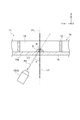
図1は、試料観察装置の一実施形態を示す概略構成図である。この試料観察装置1は、面状光L2を試料Sに照射し、試料Sの内部で発生した蛍光又は散乱光を結像面に結像させて試料S内部の観察画像データを取得する装置である。この種の試料観察装置1としては、スライドガラスに保持される試料Sの画像を取得し表示するスライドスキャナ、あるいはマイクロプレートに保持される試料Sの画像データを取得し、画像データを解析するプレートリーダなどがある。試料観察装置1は、図1に示すように、光源2と、照射光学系3と、走査部4と、結像光学系5と、画像取得部6と、コンピュータ7とを備えて構成されている。
FIG. 1 is a schematic configuration diagram illustrating an embodiment of a sample observation apparatus. The
観察対象となる試料Sとしては、例えばヒト或いは動物の細胞、組織、臓器、動物或いは植物自体、植物の細胞、組織などが挙げられる。また、試料Sは、溶液、ゲル、或いは試料Sとは屈折率の異なる物質に含まれていてもよい。 Examples of the sample S to be observed include human or animal cells, tissues, organs, animals or plants themselves, plant cells, tissues, and the like. The sample S may be contained in a solution, a gel, or a substance having a refractive index different from that of the sample S.
光源2は、試料Sに照射される光L1を出力する光源である。光源2としては、例えばレーザダイオード、固体レーザ光源といったレーザ光源が挙げられる。また、光源2は、発光ダイオード、スーパールミネッセントダイオード、ランプ系光源であってもよい。光源2から出力された光L1は、照射光学系3に導光される。
The
照射光学系3は、光源2から出力された光L1を面状光L2に整形し、整形された面状光L2を光軸P1に沿って試料Sに照射する光学系である。以下の説明では、照射光学系3の光軸P1を面状光L2の光軸という場合もある。照射光学系3は、例えばシリンドリカルレンズ、アキシコンレンズ、或いは空間光変調器などの光整形素子を含んで構成され、光源2に対して光学的に結合されている。照射光学系3は、対物レンズを含んで構成されていてもよい。照射光学系3によって形成された面状光L2は、試料Sに照射される。面状光L2が照射された試料Sでは、面状光L2の照射面Rにおいて観察光L3が発生する。観察光L3は、例えば面状光L2によって励起された蛍光、面状光L2の散乱光、或いは面状光L2の拡散反射光である。
The irradiation
試料Sの厚さ方向に観察を行う場合、分解能を考慮して、面状光L2は、厚さ2mm以下の薄い面状光であることが好ましい。また、試料Sの厚さが非常に小さい場合、すなわち、後述するZ方向解像度以下の厚さの試料Sを観察する場合には、面状光L2の厚さは分解能に影響しない。したがって、厚さ2mmを超える面状光L2を用いてもよい。 When observing in the thickness direction of the sample S, the planar light L2 is preferably thin planar light having a thickness of 2 mm or less in consideration of resolution. Further, when the thickness of the sample S is very small, that is, when observing the sample S having a thickness less than or equal to the Z-direction resolution described later, the thickness of the planar light L2 does not affect the resolution. Accordingly, the planar light L2 having a thickness exceeding 2 mm may be used.
走査部4は、面状光L2の照射面Rに対して試料Sを走査する機構である。本実施形態では、走査部4は、試料Sを保持する試料容器11を移動させる移動ステージ12によって構成されている。試料容器11は、例えばマイクロプレート、スライドガラス、シャーレ等である。本実施形態では、マイクロプレートを例示する。試料容器11は、図2に示すように、試料Sが配置される複数のウェル13が一直線状(或いはマトリクス状)に配列された板状の本体部14と、本体部14の一面側においてウェル13の一端側を塞ぐように設けられた板状の透明部材15とを有している。
The scanning unit 4 is a mechanism that scans the sample S with respect to the irradiation surface R of the planar light L2. In the present embodiment, the scanning unit 4 includes a moving
ウェル13内への試料Sの配置にあたっては、ウェル13内が水などの媒体で充填されていてもよい。透明部材15は、ウェル13内に配置された試料Sに対する面状光L2の入力面15aを有している。透明部材15の材質は、面状光L2に対する透明性を有する部材であれば特に限定はされないが、例えばガラス、石英、或いは合成樹脂である。試料容器11は、入力面15aが面状光L2の光軸P1と直交するように移動ステージ12に対して配置されている。なお、ウェル13の他端側は、外部に開放された状態となっている。試料容器11は、移動ステージ12に対して固定されていてもよい。
In arranging the sample S in the well 13, the well 13 may be filled with a medium such as water. The
移動ステージ12は、図1に示すように、コンピュータ7からの制御信号に従い、予め設定された方向に試料容器11を走査する。本実施形態では、移動ステージ12は、面状光L2の光軸P1と直交する平面内の一方向に試料容器11を走査する。以下の説明では、面状光L2の光軸P1方向をZ軸、移動ステージ12による試料容器11の走査方向をY軸、面状光L2の光軸P1と直交する平面内においてY軸に直交する方向をX軸と称する。試料Sに対する面状光L2の照射面Rは、XZ平面内の面となる。
As shown in FIG. 1, the moving
結像光学系5は、面状光L2の照射によって試料Sで発生した観察光L3を結像する光学系である。結像光学系5は、図2に示すように、例えば対物レンズ16及び結像レンズ等を含んで構成されている。結像光学系5の光軸は、観察光L3の観察軸P2となっている。この結像光学系5の観察軸P2は、試料Sにおける面状光L2の照射面Rに対して傾斜角度θをもって傾斜している。傾斜角度θは、試料Sに向かう面状光L2の光軸P1と観察軸P2とがなす角とも一致する。傾斜角度θは、10°〜80°となっている。観察画像の解像度を向上させる観点から、傾斜角度θは、20°〜70°であることが好ましい。また、観察画像の解像度の向上及び視野の安定性の観点から、傾斜角度θは、30°〜65°であることが更に好ましい。
The imaging
画像取得部6は、図1に示すように、結像光学系5によって結像された観察光L3による光像の一部に対応する部分画像データを複数取得する装置である。画像取得部6は、例えば観察光L3による光像を撮像する撮像装置を含んで構成されている。撮像装置としては、例えばCMOSイメージセンサ、CCDイメージセンサといったエリアイメージセンサが挙げられる。これらのエリアイメージセンサは、結像光学系5による結像面に配置され、例えばグローバルシャッタ或いはローリングシャッタによって光像を撮像し、二次元画像のデータをコンピュータ7に出力する。
As shown in FIG. 1, the image acquisition unit 6 is a device that acquires a plurality of partial image data corresponding to a part of the optical image by the observation light L <b> 3 imaged by the imaging
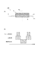
観察光L3による光像の部分画像データの取得方法については、種々の態様を採り得る。例えば図3(A)に示すように、エリアイメージセンサ21の撮像面においてサブアレイを設定してもよい。この場合、サブアレイに含まれる画素列21aのみを読み出すことができるので、観察光L3による光像の一部を撮像して部分画像データを取得できる。また、図3(B)に示すように、エリアイメージセンサ21の全ての画素列を読み出しエリアとし、その後の画像処理によって二次元画像の一部を抽出して部分画像データを取得してもよい。
Various methods can be adopted as a method of acquiring partial image data of a light image by the observation light L3. For example, as shown in FIG. 3A, a subarray may be set on the imaging surface of the
さらに、図3(C)に示すように、エリアイメージセンサ21に代えてラインセンサ22を用い、撮像面自体を一の画素列に限定して部分画像データを取得してもよい。図3(D)に示すように、観察光L3の一部のみを透過させるスリット23をエリアイメージセンサ(光検出器)21の前面に配置し、スリット23に対応する画素列21aの画像データを部分画像データとして取得してもよい。スリット23を用いる場合、エリアイメージセンサ21に代えて光電子増倍管などのポイントセンサ(光検出器)を用いてもよい。
Further, as shown in FIG. 3C, the
コンピュータ7は、物理的には、RAM、ROM等のメモリ、及びCPU等のプロセッサ(演算回路)、通信インターフェイス、ハードディスク等の格納部、ディスプレイ等の表示部を備えて構成されている。かかるコンピュータ7としては、例えばパーソナルコンピュータ、クラウドサーバ、スマートデバイス(スマートフォン、タブレット端末など)などが挙げられる。コンピュータ7は、メモリに格納されるプログラムをコンピュータシステムのCPUで実行することにより、光源2及び移動ステージ12の動作を制御するコントローラ、試料Sの観察画像データを生成する画像生成部8、及び観察画像データを解析する解析部10として機能する(図1参照)。
The
コントローラとしてのコンピュータ7は、ユーザによる測定開始の操作の入力を受け、光源2、移動ステージ12、及び画像取得部6を同期させて駆動する。この場合、コンピュータ7は、移動ステージ12による試料Sの移動中、光源2が光L1を連続的に出力するように光源2を制御してもよく、画像取得部6による撮像に合わせて光源2による光L1の出力のON/OFFを制御してもよい。また、照射光学系3が光シャッタ(不図示)を備えている場合、コンピュータ7は、当該光シャッタの制御によって試料Sへの面状光L2の照射をON/OFFさせてもよい。
A
また、画像生成部8としてのコンピュータ7は、画像取得部6によって生成された複数の部分画像データに基づいて試料Sの観察画像データを生成する。画像生成部8は、画像取得部6から出力された複数の部分画像データに基づいて、例えば面状光L2の光軸P1に直交する面(XY面)における試料Sの観察画像データを生成する。画像生成部8は、ユーザによる所定の操作に従って、生成した観察画像データの格納、モニタ等への表示等を実行する。
The
解析部10としてのコンピュータ7は、画像生成部8によって生成された観察画像データに基づいて解析を実行し、解析結果を生成する。解析部10は、ユーザによる所定の操作に従って、生成した解析結果の格納、モニタ等への表示等を実行する。なお、画像生成部によって生成された観察画像データのモニタ等への表示は行わず、解析部10によって生成された解析結果のみをモニタ等に表示してもよい。
[試料観察方法]
The
[Sample observation method]
図4は、試料観察装置を用いた試料観察方法の一例を示すフローチャートである。同図に示すように、この試料観察方法は、照射ステップ(ステップS01)、走査ステップ(ステップS02)、結像ステップ(ステップS03)、画像取得ステップ(ステップS04)、画像生成ステップ(ステップS05)、及び解析ステップ(ステップS06)を備えている。 FIG. 4 is a flowchart showing an example of a sample observation method using the sample observation apparatus. As shown in the figure, this sample observation method includes an irradiation step (step S01), a scanning step (step S02), an imaging step (step S03), an image acquisition step (step S04), and an image generation step (step S05). And an analysis step (step S06).
照射ステップS01では、試料Sに面状光L2を照射する。ユーザによって測定開始の操作が入力されると、コンピュータ7からの制御信号に基づいて光源2が駆動し、光源2から光L1が出力される。光源2から出力された光L1は、照射光学系3によって整形されて面状光L2となり、試料Sに照射される。
In the irradiation step S01, the sample S is irradiated with the planar light L2. When a measurement start operation is input by the user, the
走査ステップS02では、面状光L2の照射面Rに対して試料Sを走査する。ユーザによって測定開始の操作が入力されると、コンピュータ7からの制御信号に基づいて、光源2の駆動と同期して移動ステージ12が駆動する。これにより、試料容器11がY軸方向に一定の速度で直線的に駆動し、面状光L2の照射面Rに対してウェル13内の試料Sが走査される。
In the scanning step S02, the sample S is scanned with respect to the irradiation surface R of the planar light L2. When a measurement start operation is input by the user, the moving
結像ステップS03では、照射面Rに対して傾斜する観察軸P2を有する結像光学系5を用い、面状光L2の照射によって試料Sで発生した観察光L3を画像取得部6の結像面に対して結像する。画像取得ステップS04では、結像光学系5によって結像された観察光L3による光像の一部に対応する部分画像データを複数取得する。部分画像データは、画像取得部6から画像生成部8に順次出力される。
In the imaging step S03, the imaging
画像生成ステップS05では、複数の部分画像データに基づいて試料Sの観察画像データを生成する。本実施形態では、図1及び図2に示したように、試料Sに対する面状光L2の照射面Rは、XZ平面内の面であり、試料Sに対して照射面RがY軸方向に走査される。したがって、画像生成部8には、図5(A)に示すように、部分画像データであるXZ断面画像データ31をY軸方向に複数取得することによって、試料Sの3次元情報が蓄積される。画像生成部8では、複数のXZ断面画像を用いてデータが再構築され、例えば図5(B)に示すように、試料SにおけるZ軸方向の任意の位置において任意の厚さを持ったXY断面画像が、バックグラウンドを抑えた観察画像32として生成される。
In the image generation step S05, observation image data of the sample S is generated based on the plurality of partial image data. In the present embodiment, as shown in FIGS. 1 and 2, the irradiation surface R of the planar light L2 on the sample S is a surface in the XZ plane, and the irradiation surface R with respect to the sample S is in the Y-axis direction. Scanned. Therefore, as shown in FIG. 5A, the
解析ステップS06では、解析部10によって観察画像データを解析し、解析結果を生成する。例えば創薬スクリーニングでは、試料容器11に試料S及び試薬を入れ、観察画像データを取得する。そして、解析部10は、観察画像データに基づいて試薬を評価し、評価データを解析結果として生成する。
[作用効果]
In the analysis step S06, the observation image data is analyzed by the
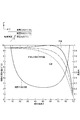
[Function and effect]
比較例に係る試料観察装置100は、図6(A)に示すように、面状光L2の照射面Rに対して直交する観察軸P2を有している。この試料観察装置100では、観察光学系のフォーカス面の全面に面状光L2を照射することで、1回の撮像によって試料Sにおける観察軸P2方向に直交する断層面の画像を取得し得る。したがって、試料Sの3次元情報を取得するためには、観察軸P2方向に試料Sを走査し、観察軸P2方向に直交する複数の断層面の画像を取得する必要があった。このような比較例に係る試料観察装置100では、図6(B)に示すように、全ての断層面の画像を取得するまでに、画像を取得する断層面の選択(試料Sの走査及び停止)と画像取得とを繰り返す必要があった。また、観察対象が存在する領域が撮像よりも広い場合には、観察軸P2方向の断面画像を取得する動作に加え、観察軸方向とは異なる方向へステージを移動することにより撮像視野を選択する動作などが必要となっていた。
As shown in FIG. 6A, the
これに対し、実施例に係る試料観察装置1では、図7(A)に示すように、面状光L2の照射面Rに対して試料Sを走査しながら画像取得部6によって画像取得を行い、また、面状光L2の照射面Rに対し、結像光学系5の観察軸P2が傾斜している。このため、画像取得部6では、面状光L2の光軸P1方向(Z軸方向)における断層面の部分画像データを順次取得することが可能となり、画像生成部8では、複数の部分画像データに基づいて、試料Sの観察画像データ32を生成できる。
On the other hand, in the
この試料観察装置1では、図7(B)に示すように、試料Sを走査させながら画像取得を順次行うことが可能となる。比較例に係る試料観察装置100の動作では、移動ステージ12の駆動及び停止の際の度に、慣性の影響等により時間的なロスが生じる。一方、試料観察装置1では、移動ステージ12の駆動及び停止の回数を削減し、試料Sの走査動作と画像取得とを同時進行することで、観察画像データ32を得るまでのスループットの向上が図られる。
In this
また、試料観察装置1では、図2に示したように、試料Sが面状光L2の入力面15aを有する試料容器11によって保持され、照射光学系3による面状光L2の光軸P1が試料容器11の入力面15aに対して直交するように配置されている。さらに、試料観察装置1では、照射光学系3による面状光L2の光軸P1(Z軸方向)に対して直交する方向(Y軸方向)に走査部4が試料Sを走査する。これにより、画像取得部6で取得した部分画像データの位置補正などの画像処理が不要となり、観察画像データの生成処理を容易化できる。
Further, in the
また、試料観察装置1では、試料Sにおける面状光L2の照射面Rに対する結像光学系5の観察軸P2の傾斜角度θが10°〜80°、好ましくは、20°〜70°、より好ましくは30°〜65°となっている。以下、この点について考察する。
Moreover, in the
図8は、試料観察装置における視野の算出例を示す図である。同図に示す例では、結像光学系が屈折率n1の媒質A中に位置し、面状光の照射面が屈折率n2の媒質B中に位置している。結像光学系における視野をV、照射面をV’、照射面に対する観察軸の傾斜角度をθ、媒質A,Bの境界面での屈折角をθ’、視野Vの傾斜角度θにおける媒質Aと媒質Bの界面での距離をLとした場合、以下の式(1)〜(3)が成り立つ。
(数1)
FIG. 8 is a diagram illustrating a calculation example of the visual field in the sample observation apparatus. In the example shown in the figure, the imaging optical system is located in the medium A having the refractive index n1, and the irradiation surface of the planar light is located in the medium B having the refractive index n2. The field A in the imaging optical system is V, the irradiation surface is V ′, the tilt angle of the observation axis with respect to the irradiation surface is θ, the refraction angle at the boundary surface between the media A and B is θ ′, and the medium A at the tilt angle θ of the field V. When the distance at the interface between the medium B and the medium B is L, the following equations (1) to (3) hold.
(Equation 1)
L=V/cosθ …(1)
(数2)
L = V / cos θ (1)
(Equation 2)
sinθ’=(n1/n2)sinθ …(2)
(数3)
sin θ ′ = (n1 / n2) sin θ (2)
(Equation 3)
V’=L/tanθ’ …(3) V ′ = L / tan θ ′ (3)
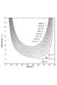
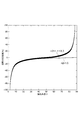
図9は、観察軸の傾斜角度と解像度との関係を示す図である。同図では、横軸を観察軸の傾斜角度θとし、縦軸を視野の相対値V’/Vとしている。そして、媒質Aの屈折率n1を1(空気)とし、媒質Bの屈折率n2を1.0から2.0まで0.1刻みで変化させたときのV’/Vの値を傾斜角度θに対してプロットしたものである。V’/Vの値が小さいほど試料の深さ方向の解像度(以下、「Z方向解像度」と称す)が高く、大きいほどZ方向解像度が低いことを示している。 FIG. 9 is a diagram showing the relationship between the tilt angle of the observation axis and the resolution. In this figure, the horizontal axis is the tilt angle θ of the observation axis, and the vertical axis is the relative value V ′ / V of the visual field. Then, when the refractive index n1 of the medium A is 1 (air) and the refractive index n2 of the medium B is changed from 1.0 to 2.0 in increments of 0.1, the value of V ′ / V is the inclination angle θ. Is plotted against. The smaller the value of V ′ / V, the higher the resolution in the depth direction of the sample (hereinafter referred to as “Z-direction resolution”), and the higher the value, the lower the Z-direction resolution.
図9に示す結果から、媒質Aの屈折率n1と媒質Bの屈折率n2とが等しい場合には、傾斜角度θに対してV’/Vの値が反比例していることが分かる。また、媒質Aの屈折率n1と媒質Bの屈折率n2とが異なる場合には、傾斜角度θに対してV’/Vの値が放物線を描くことが分かる。この結果から、試料の配置空間の屈折率、結像光学系の配置空間の屈折率、及び観察軸の傾斜角度θによってZ方向解像度をコントロールできることが分かる。そして、傾斜角度θが10°〜80°の範囲では、傾斜角度θが10°未満及び80°を超える範囲に比べて良好なZ方向解像度が得られることが分かる。 From the results shown in FIG. 9, it can be seen that when the refractive index n1 of the medium A is equal to the refractive index n2 of the medium B, the value of V ′ / V is inversely proportional to the inclination angle θ. Further, it can be seen that when the refractive index n1 of the medium A and the refractive index n2 of the medium B are different, the value of V ′ / V draws a parabola with respect to the inclination angle θ. From this result, it can be seen that the Z-direction resolution can be controlled by the refractive index of the arrangement space of the sample, the refractive index of the arrangement space of the imaging optical system, and the tilt angle θ of the observation axis. It can be seen that in the range of the tilt angle θ of 10 ° to 80 °, a better Z-direction resolution can be obtained compared to the range of the tilt angle θ of less than 10 ° and greater than 80 °.
また、図9に示す結果から、Z方向解像度が最大となる傾斜角度θは、屈折率n1と屈折率n2との差が大きくなるにつれて小さく傾向があることが分かる。屈折率n2が1.1〜2.0の範囲では、Z方向解像度が最大となる傾斜角度θは、約47°〜約57°の範囲となる。例えば屈折率n2が1.33(水)の場合、Z方向解像度が最大となる傾斜角度θは、およそ52°と見積もられる。また、例えば屈折率n2が1.53(ガラス)の場合、Z方向解像度が最大となる傾斜角度θは、およそ48°と見積もられる。 Further, it can be seen from the results shown in FIG. 9 that the inclination angle θ at which the Z-direction resolution is maximized tends to decrease as the difference between the refractive index n1 and the refractive index n2 increases. When the refractive index n2 is in the range of 1.1 to 2.0, the inclination angle θ at which the Z-direction resolution is maximized is in the range of about 47 ° to about 57 °. For example, when the refractive index n2 is 1.33 (water), the inclination angle θ at which the Z-direction resolution is maximized is estimated to be approximately 52 °. For example, when the refractive index n2 is 1.53 (glass), the inclination angle θ at which the Z-direction resolution is maximized is estimated to be about 48 °.
図10は、観察軸の傾斜角度と視野の安定度との関係を示す図である。同図では、横軸を観察軸の傾斜角度θとし、縦軸を視野の安定度としている。安定度は、傾斜角度θでのV’/Vに対する傾斜角度θ+1でのV’/Vと傾斜角度θ−1でのV’/Vとの差分値の割合で表され、下記式(4)に基づいて算出される。安定度が0%に近い程、傾斜角度の変化に対する視野の変化が小さく、視野が安定していると評価できる。この図10では、図9と同様に、媒質Aの屈折率n1を1(空気)とし、媒質Bの屈折率n2を1.0から2.0まで0.1刻みで変化させたときの安定度がプロットされている。
(数4)
FIG. 10 is a diagram illustrating the relationship between the tilt angle of the observation axis and the stability of the visual field. In this figure, the horizontal axis is the tilt angle θ of the observation axis, and the vertical axis is the stability of the visual field. The stability is expressed as a ratio of a difference value between V ′ / V at the inclination angle θ + 1 and V ′ / V at the inclination angle θ−1 with respect to V ′ / V at the inclination angle θ, and the following formula (4) Is calculated based on It can be evaluated that the closer the stability is to 0%, the smaller the change in the visual field with respect to the change in the tilt angle, and the more stable the visual field. In FIG. 10, as in FIG. 9, the stability when the refractive index n1 of the medium A is 1 (air) and the refractive index n2 of the medium B is changed from 1.0 to 2.0 in increments of 0.1. The degree is plotted.
(Equation 4)
安定度(%)=((V’/V)θ+1−(V’/V)θ−1)/(V’/V)θ …(4) Stability (%) = ((V ′ / V) θ + 1− (V ′ / V) θ−1 ) / (V ′ / V) θ (4)
図10に示す結果から、傾斜角度θが10°未満及び80°を超える範囲では、安定度が±20%を超えており、視野のコントロールが困難であることが分かる。一方、傾斜角度θが10°〜80°の範囲では、安定度が±20%以下となり、視野のコントロールが可能となる。さらに、傾斜角度θが20°〜70°の範囲では、安定度が±10%以下となり、視野のコントロールが容易となる。 From the results shown in FIG. 10, it can be seen that when the tilt angle θ is less than 10 ° and more than 80 °, the stability exceeds ± 20% and it is difficult to control the visual field. On the other hand, when the tilt angle θ is in the range of 10 ° to 80 °, the stability is ± 20% or less, and the visual field can be controlled. Further, when the inclination angle θ is in the range of 20 ° to 70 °, the stability is ± 10% or less, and the visual field can be easily controlled.
図11は、観察軸の傾斜角度と試料からの観察光の透過率との関係を示す図である。同図では、横軸を観察軸の傾斜角度θとし、左側の縦軸を視野の相対値、右側の縦軸を透過率としている。この図11では、試料容器における試料の保持状態を考慮し、媒質Aの屈折率n1を1(空気)、媒質Bの屈折率n2を1.53(ガラス)、媒質Cの屈折率n3を1.33(水)とし、透過率の値は、媒質B,Cの界面及び媒質A,Bの界面の透過率の積としている。図11には、P波の透過率、S波の透過率、及びこれらの平均値の角度依存性がプロットされている。また、図11には、媒質Cにおける視野の相対値が併せてプロットされている。 FIG. 11 is a diagram showing the relationship between the tilt angle of the observation axis and the transmittance of observation light from the sample. In the figure, the horizontal axis is the tilt angle θ of the observation axis, the left vertical axis is the relative value of the visual field, and the right vertical axis is the transmittance. In FIG. 11, taking into consideration the holding state of the sample in the sample container, the refractive index n1 of the medium A is 1 (air), the refractive index n2 of the medium B is 1.53 (glass), and the refractive index n3 of the medium C is 1. .33 (water), and the transmittance value is the product of the transmittances of the interfaces of the media B and C and the interfaces of the media A and B. FIG. 11 plots the P wave transmittance, the S wave transmittance, and the angle dependency of the average of these. Further, in FIG. 11, the relative values of the visual field in the medium C are also plotted.
図11に示す結果から、観察軸の傾斜角度θを変化させることで、試料から結像光学系に至る観察光の透過率が可変となることが分かる。傾斜角度θが80°以下の範囲では、少なくとも50%以上の透過率が得られることが分かる。また、傾斜角度θが70°以下の範囲では、少なくとも60%以上の透過率が得られ、傾斜角度θが65°以下の範囲では、少なくとも75%以上の透過率が得られることが分かる。 From the results shown in FIG. 11, it can be seen that the transmittance of the observation light from the sample to the imaging optical system can be changed by changing the inclination angle θ of the observation axis. It can be seen that a transmittance of at least 50% or more can be obtained when the inclination angle θ is in the range of 80 ° or less. It can also be seen that a transmittance of at least 60% is obtained when the tilt angle θ is 70 ° or less, and a transmittance of at least 75% is obtained when the tilt angle θ is 65 ° or less.
以上の結果から、試料のZ方向解像度が要求される場合には、例えば視野の相対値であるV’/Vの値が3以下であり、安定度が5%未満、かつ観察光の透過率(P波及びS波の平均値)が75%以上となるように、傾斜角度θを30°〜65°の範囲から選択することが好適である。また、試料のZ方向解像度が要求されない場合には、傾斜角度θを10°〜80°の範囲から適宜選択すればよく、1画素当たりの視野の範囲を確保する観点から、10°〜30°若しくは65°〜80°の範囲から選択することが好適である。 From the above results, when the Z-direction resolution of the sample is required, for example, the value of V ′ / V, which is the relative value of the visual field, is 3 or less, the stability is less than 5%, and the transmittance of the observation light It is preferable to select the inclination angle θ from a range of 30 ° to 65 ° so that (average value of P wave and S wave) is 75% or more. Further, when the Z-direction resolution of the sample is not required, the inclination angle θ may be appropriately selected from the range of 10 ° to 80 °, and 10 ° to 30 ° from the viewpoint of securing the field of view per pixel. Or it is suitable to select from the range of 65 degrees-80 degrees.
本発明は、上記実施形態に限られるものではない。例えば面状光L2の光軸P1と試料容器11の入力面15aとは、必ずしも直交していなくてもよく、面状光L2の光軸P1と走査部4による試料Sの走査方向とは、必ずしも直交していなくてもよい。
The present invention is not limited to the above embodiment. For example, the optical axis P1 of the planar light L2 and the
また、例えば上記実施形態では、試料容器11においてウェル13の一端側を塞ぐように透明部材15が設けられており、透明部材15の入力面15aから面状光L2を入力させているが、ウェル13の他端側から面状光L2を入力させる構成としてもよい。この場合、屈折率が異なる媒質の界面の数が少なくなり、観察光L3の屈折回数を減らすことが可能となる。さらに、試料容器11に代えて、ゲル等の固形物に試料Sを保持してもよく、フローサイトメーターのように、透明容器内に水等の流体を流して試料Sを移動させるようにしてもよい。
Further, for example, in the above-described embodiment, the
また、結像光学系5及び画像取得部6を複数対配置してもよい。この場合、観察範囲を拡大できるほか、複数の異なる波長の観察光L3を観察することが可能となる。また、結像光学系5に対して複数の画像取得部6を配置してもよく、複数の結像光学系5に対して画像取得部6を配置してもよい。複数の画像取得部6は、異なる種類の光検出器あるいは撮像装置を組み合わせてもよい。光源2は、波長の異なる光を出力する複数の光源によって構成されてもよい。この場合、波長の異なる励起光を試料Sに照射することができる。
A plurality of pairs of the imaging
また、非点収差の緩和のため、結像光学系5にプリズムを配置してもよい。この場合、例えば図12に示すように、対物レンズ16の後段側(対物レンズ16と画像取得部6との間)にプリズム41を配置してもよい。デフォーカス対策のため、観察軸P2に対して画像取得部6における撮像装置の撮像面を傾斜させてもよい。この他、例えば結像光学系5と画像取得部6との間にダイクロイックミラー或いはプリズムを配置して観察光L3の波長分離を行う構成としてもよい。
In addition, a prism may be disposed in the imaging
1…試料観察装置、3…照射光学系、4…走査部、5…結像光学系、6…画像取得部、8…画像生成部、10…解析部、11…試料容器、15a…入力面、21…エリアイメージセンサ(撮像装置)、22…ラインセンサ、23…スリット、31…部分画像データ、32…観察画像データ、L2…面状光、L3…観察光、P2…観察軸、R…照射面、S…試料、θ…傾斜角度。
DESCRIPTION OF
Claims (12)
前記面状光の照射面に対して前記試料を一定の速度で走査する走査部と、
前記照射面に対して傾斜する観察軸を有し、前記面状光の照射によって前記試料で発生した観察光を結像する結像光学系と、
前記走査部による前記試料の走査中に、前記結像光学系によって結像された前記観察光による光像の一部に対応する部分画像データを複数取得する画像取得部と、
前記画像取得部によって生成された複数の部分画像データに基づいて前記試料の観察画像データを生成する画像生成部と、を備えた試料観察装置。 An irradiation optical system for irradiating the sample with planar light; and
A scanning unit that scans the sample at a constant speed with respect to the irradiation surface of the planar light;
An imaging optical system having an observation axis inclined with respect to the irradiation surface, and imaging the observation light generated in the sample by the irradiation of the planar light;
An image acquisition unit for acquiring a plurality of partial image data corresponding to a part of the optical image by the observation light imaged by the imaging optical system during scanning of the sample by the scanning unit;
A sample observation apparatus comprising: an image generation unit that generates observation image data of the sample based on a plurality of partial image data generated by the image acquisition unit.
前記照射光学系による前記面状光の光軸は、前記試料容器の前記入力面に対して直交するように配置されている請求項1記載の試料観察装置。 The sample is held by a sample container having an input surface for the planar light,
The sample observation apparatus according to claim 1, wherein an optical axis of the planar light by the irradiation optical system is arranged so as to be orthogonal to the input surface of the sample container.
前記面状光の照射面に対して前記試料を一定の速度で走査する走査ステップと、
前記照射面に対して傾斜する観察軸を有する結像光学系を用い、前記面状光の照射によって前記試料で発生した観察光を結像する結像ステップと、
前記走査ステップによる前記試料の走査中に、前記結像光学系によって結像された前記観察光による光像の一部に対応する部分画像データを複数取得する画像取得ステップと、
前記複数の部分画像データに基づいて前記試料の観察画像データを生成する画像生成ステップと、を備えた試料観察方法。 An irradiation step of irradiating the sample with planar light;
A scanning step of scanning the sample at a constant speed with respect to the irradiation surface of the planar light;
Using an imaging optical system having an observation axis inclined with respect to the irradiation surface, an imaging step of forming an image of the observation light generated on the sample by the irradiation of the planar light;
An image acquisition step of acquiring a plurality of partial image data corresponding to a part of the optical image by the observation light imaged by the imaging optical system during the scanning of the sample by the scanning step ;
An image generation step of generating observation image data of the sample based on the plurality of partial image data.
Priority Applications (8)
| Application Number | Priority Date | Filing Date | Title |
|---|---|---|---|
| JP2016200075A JP6423841B2 (en) | 2016-10-11 | 2016-10-11 | Sample observation apparatus and sample observation method |
| CN201780062595.5A CN109844606A (en) | 2016-10-11 | 2017-08-15 | Sample observes device and sample observation method |
| US16/340,797 US10809509B2 (en) | 2016-10-11 | 2017-08-15 | Sample observation device and sample observation method |
| EP17859579.9A EP3528030A4 (en) | 2016-10-11 | 2017-08-15 | Sample observation device and sample observation method |
| PCT/JP2017/029367 WO2018070098A1 (en) | 2016-10-11 | 2017-08-15 | Sample observation device and sample observation method |
| US17/006,995 US11131839B2 (en) | 2016-10-11 | 2020-08-31 | Sample observation device and sample observation method |
| US17/411,533 US11391934B2 (en) | 2016-10-11 | 2021-08-25 | Sample observation device and sample observation method |
| US17/751,818 US11822066B2 (en) | 2016-10-11 | 2022-05-24 | Sample observation device and sample observation method |
Applications Claiming Priority (1)
| Application Number | Priority Date | Filing Date | Title |
|---|---|---|---|
| JP2016200075A JP6423841B2 (en) | 2016-10-11 | 2016-10-11 | Sample observation apparatus and sample observation method |
Related Child Applications (1)
| Application Number | Title | Priority Date | Filing Date |
|---|---|---|---|
| JP2018197569A Division JP6754408B2 (en) | 2018-10-19 | 2018-10-19 | Sample observation device and sample observation method |
Publications (3)
| Publication Number | Publication Date |
|---|---|
| JP2018063292A JP2018063292A (en) | 2018-04-19 |
| JP2018063292A5 JP2018063292A5 (en) | 2018-07-12 |
| JP6423841B2 true JP6423841B2 (en) | 2018-11-14 |
Family
ID=61905513
Family Applications (1)
| Application Number | Title | Priority Date | Filing Date |
|---|---|---|---|
| JP2016200075A Active JP6423841B2 (en) | 2016-10-11 | 2016-10-11 | Sample observation apparatus and sample observation method |
Country Status (5)
| Country | Link |
|---|---|
| US (4) | US10809509B2 (en) |
| EP (1) | EP3528030A4 (en) |
| JP (1) | JP6423841B2 (en) |
| CN (1) | CN109844606A (en) |
| WO (1) | WO2018070098A1 (en) |
Families Citing this family (6)
| Publication number | Priority date | Publication date | Assignee | Title |
|---|---|---|---|---|
| JP7207860B2 (en) * | 2018-04-09 | 2023-01-18 | 浜松ホトニクス株式会社 | Sample observation device |
| CN115668027A (en) | 2020-05-27 | 2023-01-31 | 浜松光子学株式会社 | Light irradiation device and sample observation device |
| WO2021246021A1 (en) * | 2020-06-01 | 2021-12-09 | 浜松ホトニクス株式会社 | Sample observation device and sample observation method |
| US20240184090A1 (en) | 2021-07-26 | 2024-06-06 | Hamamatsu Photonics K.K. | Sample observation device and sample observation method |
| JP2024093375A (en) | 2022-12-27 | 2024-07-09 | 浜松ホトニクス株式会社 | Sample observation device and sample observation method |
| JP2024093373A (en) | 2022-12-27 | 2024-07-09 | 浜松ホトニクス株式会社 | Sample observation device and sample observation method |
Family Cites Families (38)
| Publication number | Priority date | Publication date | Assignee | Title |
|---|---|---|---|---|
| JPS62180241A (en) | 1986-02-04 | 1987-08-07 | Hamamatsu Photonics Kk | Tomographic image observing device |
| JPH03172815A (en) | 1989-12-01 | 1991-07-26 | Fuji Photo Film Co Ltd | Cofocus scanning type microscope |
| JPH11211439A (en) | 1998-01-22 | 1999-08-06 | Takaoka Electric Mfg Co Ltd | Surface form measuring device |
| JP3736213B2 (en) | 1999-07-15 | 2006-01-18 | 横河電機株式会社 | Confocal light scanner |
| DE10257423A1 (en) * | 2002-12-09 | 2004-06-24 | Europäisches Laboratorium für Molekularbiologie (EMBL) | Microscope used in molecular biology comprises a focussing arrangement producing an extended planar object illumination region, a detection device, and a movement arrangement |
| US7009172B2 (en) * | 2003-03-06 | 2006-03-07 | Board Of Regents Of The University And Community College System Of Nevada, Reno | Method and apparatus for imaging using continuous non-raster patterns |
| US7345814B2 (en) * | 2003-09-29 | 2008-03-18 | Olympus Corporation | Microscope system and microscope focus maintaining device for the same |
| JP4621866B2 (en) | 2004-03-16 | 2011-01-26 | 学校法人日本大学 | Fuel combustion propagation analysis and flame spread measurement apparatus, and fuel flame propagation mode test method using the apparatus |
| US20050280892A1 (en) * | 2004-05-28 | 2005-12-22 | Nobuyuki Nagasawa | Examination method and examination apparatus |
| JP4538633B2 (en) | 2005-03-29 | 2010-09-08 | 国立大学法人浜松医科大学 | DLP slit optical scanning microscope |
| JP4890096B2 (en) * | 2006-05-19 | 2012-03-07 | 浜松ホトニクス株式会社 | Image acquisition apparatus, image acquisition method, and image acquisition program |
| CN101918816B (en) * | 2007-12-21 | 2015-12-02 | 哈佛大学 | Sub-diffraction limit image resolution in three-dimensional |
| WO2010014244A2 (en) | 2008-07-30 | 2010-02-04 | The Regents Of The University Of California, San Francisco | Multidirectional selective plane illumination microscopy |
| GB0814039D0 (en) * | 2008-07-31 | 2008-09-10 | Imp Innovations Ltd | Optical arrangement for oblique plane microscopy |
| JP2010054391A (en) * | 2008-08-29 | 2010-03-11 | Nano Photon Kk | Optical microscope, and method of displaying color image |
| JP5311195B2 (en) * | 2008-09-16 | 2013-10-09 | 横河電機株式会社 | Microscope equipment |
| US9116353B2 (en) * | 2008-09-16 | 2015-08-25 | Yokogawa Electric Corporation | Microscope device |
| EP2344864B1 (en) * | 2008-10-24 | 2020-05-06 | Leica Biosystems Imaging, Inc. | Whole slide fluorescence scanner |
| JP2011180442A (en) * | 2010-03-02 | 2011-09-15 | Sony Corp | Device, method and program for acquisition of sample image |
| US8711211B2 (en) | 2010-06-14 | 2014-04-29 | Howard Hughes Medical Institute | Bessel beam plane illumination microscope |
| WO2013010151A1 (en) | 2011-07-14 | 2013-01-17 | Howard Hughes Medical Institute | Microscopy with adaptive optics |
| EP2766765B1 (en) | 2011-10-11 | 2018-08-15 | Carl Zeiss Microscopy GmbH | Microscope and method for spim microscopy |
| JP2013156286A (en) | 2012-01-26 | 2013-08-15 | Olympus Corp | Imaging apparatus |
| DE102012110077A1 (en) | 2012-10-23 | 2014-06-26 | Karlsruher Institut für Technologie | Microscope with at least one illumination beam in the form of a lens |
| JP6086366B2 (en) | 2013-04-05 | 2017-03-01 | 国立研究開発法人理化学研究所 | Microscope, focusing device, fluid holding device, and optical unit |
| JP6010505B2 (en) * | 2013-06-11 | 2016-10-19 | 浜松ホトニクス株式会社 | Image acquisition device and focus method of image acquisition device |
| DE102013107297A1 (en) * | 2013-07-10 | 2015-01-15 | Carl Zeiss Microscopy Gmbh | Arrangement for light-sheet microscopy |
| JP2015135463A (en) * | 2013-12-19 | 2015-07-27 | オリンパス株式会社 | Microscope apparatus and microscope system |
| US10061111B2 (en) * | 2014-01-17 | 2018-08-28 | The Trustees Of Columbia University In The City Of New York | Systems and methods for three dimensional imaging |
| DE102014102215A1 (en) * | 2014-02-20 | 2015-08-20 | Carl Zeiss Microscopy Gmbh | Method and arrangement for light-sheet microscopy |
| JP2016033620A (en) * | 2014-07-31 | 2016-03-10 | キヤノン株式会社 | Image acquisition device |
| EP3108284B1 (en) | 2014-12-22 | 2018-03-14 | Koninklijke Philips N.V. | Method and device for simultaneous capture of image data at multiple depths of a sample |
| JP6605269B2 (en) * | 2015-09-24 | 2019-11-13 | オリンパス株式会社 | Inverted microscope and light shielding device for inverted microscope |
| JP2017191228A (en) * | 2016-04-14 | 2017-10-19 | オリンパス株式会社 | Light sheet microscope and sample observation method |
| US10409052B2 (en) * | 2016-09-28 | 2019-09-10 | University Of Washington | Inverted light-sheet microscope |
| EP3610313B1 (en) * | 2017-04-11 | 2022-03-02 | Calico Life Sciences LLC | Fluorescence microscopy system and methods based on stimulated emission |
| EP3814823A4 (en) * | 2018-05-10 | 2022-02-23 | Board of Regents, The University of Texas System | Line excitation array detection microscopy |
| DE102019100184A1 (en) * | 2019-01-07 | 2020-07-09 | Carl Zeiss Microscopy Gmbh | High resolution scanning microscopy |
-
2016
- 2016-10-11 JP JP2016200075A patent/JP6423841B2/en active Active
-
2017
- 2017-08-15 WO PCT/JP2017/029367 patent/WO2018070098A1/en unknown
- 2017-08-15 EP EP17859579.9A patent/EP3528030A4/en active Pending
- 2017-08-15 US US16/340,797 patent/US10809509B2/en active Active
- 2017-08-15 CN CN201780062595.5A patent/CN109844606A/en active Pending
-
2020
- 2020-08-31 US US17/006,995 patent/US11131839B2/en active Active
-
2021
- 2021-08-25 US US17/411,533 patent/US11391934B2/en active Active
-
2022
- 2022-05-24 US US17/751,818 patent/US11822066B2/en active Active
Also Published As
| Publication number | Publication date |
|---|---|
| US20200393661A1 (en) | 2020-12-17 |
| EP3528030A4 (en) | 2020-05-27 |
| US11822066B2 (en) | 2023-11-21 |
| JP2018063292A (en) | 2018-04-19 |
| WO2018070098A1 (en) | 2018-04-19 |
| US11131839B2 (en) | 2021-09-28 |
| EP3528030A1 (en) | 2019-08-21 |
| US11391934B2 (en) | 2022-07-19 |
| US20220283420A1 (en) | 2022-09-08 |
| US10809509B2 (en) | 2020-10-20 |
| CN109844606A (en) | 2019-06-04 |
| US20200041776A1 (en) | 2020-02-06 |
| US20210382286A1 (en) | 2021-12-09 |
Similar Documents
| Publication | Publication Date | Title |
|---|---|---|
| JP6423841B2 (en) | Sample observation apparatus and sample observation method | |
| US20230314782A1 (en) | Sample observation device and sample observation method | |
| CN111971607B (en) | Sample observation device | |
| JP7007227B2 (en) | Sample observation device and sample observation method | |
| JP6978562B2 (en) | Sample observation device and sample observation method | |
| JP6754408B2 (en) | Sample observation device and sample observation method | |
| JP7329113B2 (en) | Sample observation device | |
| US20230184681A1 (en) | Sample observation device and sample observation method | |
| US20240184090A1 (en) | Sample observation device and sample observation method |
Legal Events
| Date | Code | Title | Description |
|---|---|---|---|
| A521 | Request for written amendment filed |
Free format text: JAPANESE INTERMEDIATE CODE: A523 Effective date: 20180530 |
|
| A621 | Written request for application examination |
Free format text: JAPANESE INTERMEDIATE CODE: A621 Effective date: 20180530 |
|
| A871 | Explanation of circumstances concerning accelerated examination |
Free format text: JAPANESE INTERMEDIATE CODE: A871 Effective date: 20180530 |
|
| A975 | Report on accelerated examination |
Free format text: JAPANESE INTERMEDIATE CODE: A971005 Effective date: 20180730 |
|
| A131 | Notification of reasons for refusal |
Free format text: JAPANESE INTERMEDIATE CODE: A131 Effective date: 20180807 |
|
| A521 | Request for written amendment filed |
Free format text: JAPANESE INTERMEDIATE CODE: A523 Effective date: 20180821 |
|
| TRDD | Decision of grant or rejection written | ||
| A01 | Written decision to grant a patent or to grant a registration (utility model) |
Free format text: JAPANESE INTERMEDIATE CODE: A01 Effective date: 20181016 |
|
| A61 | First payment of annual fees (during grant procedure) |
Free format text: JAPANESE INTERMEDIATE CODE: A61 Effective date: 20181019 |
|
| R150 | Certificate of patent or registration of utility model |
Ref document number: 6423841 Country of ref document: JP Free format text: JAPANESE INTERMEDIATE CODE: R150 |