JP6423787B2 - Devices, systems, and methods for transcatheter treatment of valvular reflux - Google Patents
Devices, systems, and methods for transcatheter treatment of valvular reflux Download PDFInfo
- Publication number
- JP6423787B2 JP6423787B2 JP2015518499A JP2015518499A JP6423787B2 JP 6423787 B2 JP6423787 B2 JP 6423787B2 JP 2015518499 A JP2015518499 A JP 2015518499A JP 2015518499 A JP2015518499 A JP 2015518499A JP 6423787 B2 JP6423787 B2 JP 6423787B2
- Authority
- JP
- Japan
- Prior art keywords
- anchor
- valve
- joint implant
- implant
- joint
- Prior art date
- Legal status (The legal status is an assumption and is not a legal conclusion. Google has not performed a legal analysis and makes no representation as to the accuracy of the status listed.)
- Active
Links
Images


Classifications
-
- A—HUMAN NECESSITIES
- A61—MEDICAL OR VETERINARY SCIENCE; HYGIENE
- A61F—FILTERS IMPLANTABLE INTO BLOOD VESSELS; PROSTHESES; DEVICES PROVIDING PATENCY TO, OR PREVENTING COLLAPSING OF, TUBULAR STRUCTURES OF THE BODY, e.g. STENTS; ORTHOPAEDIC, NURSING OR CONTRACEPTIVE DEVICES; FOMENTATION; TREATMENT OR PROTECTION OF EYES OR EARS; BANDAGES, DRESSINGS OR ABSORBENT PADS; FIRST-AID KITS
- A61F2/00—Filters implantable into blood vessels; Prostheses, i.e. artificial substitutes or replacements for parts of the body; Appliances for connecting them with the body; Devices providing patency to, or preventing collapsing of, tubular structures of the body, e.g. stents
- A61F2/02—Prostheses implantable into the body
- A61F2/24—Heart valves ; Vascular valves, e.g. venous valves; Heart implants, e.g. passive devices for improving the function of the native valve or the heart muscle; Transmyocardial revascularisation [TMR] devices; Valves implantable in the body
- A61F2/2442—Annuloplasty rings or inserts for correcting the valve shape; Implants for improving the function of a native heart valve
- A61F2/2466—Delivery devices therefor
-
- A—HUMAN NECESSITIES
- A61—MEDICAL OR VETERINARY SCIENCE; HYGIENE
- A61B—DIAGNOSIS; SURGERY; IDENTIFICATION
- A61B17/00—Surgical instruments, devices or methods, e.g. tourniquets
- A61B17/04—Surgical instruments, devices or methods, e.g. tourniquets for suturing wounds; Holders or packages for needles or suture materials
- A61B17/0401—Suture anchors, buttons or pledgets, i.e. means for attaching sutures to bone, cartilage or soft tissue; Instruments for applying or removing suture anchors
-
- A—HUMAN NECESSITIES
- A61—MEDICAL OR VETERINARY SCIENCE; HYGIENE
- A61F—FILTERS IMPLANTABLE INTO BLOOD VESSELS; PROSTHESES; DEVICES PROVIDING PATENCY TO, OR PREVENTING COLLAPSING OF, TUBULAR STRUCTURES OF THE BODY, e.g. STENTS; ORTHOPAEDIC, NURSING OR CONTRACEPTIVE DEVICES; FOMENTATION; TREATMENT OR PROTECTION OF EYES OR EARS; BANDAGES, DRESSINGS OR ABSORBENT PADS; FIRST-AID KITS
- A61F2/00—Filters implantable into blood vessels; Prostheses, i.e. artificial substitutes or replacements for parts of the body; Appliances for connecting them with the body; Devices providing patency to, or preventing collapsing of, tubular structures of the body, e.g. stents
- A61F2/02—Prostheses implantable into the body
- A61F2/24—Heart valves ; Vascular valves, e.g. venous valves; Heart implants, e.g. passive devices for improving the function of the native valve or the heart muscle; Transmyocardial revascularisation [TMR] devices; Valves implantable in the body
- A61F2/2442—Annuloplasty rings or inserts for correcting the valve shape; Implants for improving the function of a native heart valve
- A61F2/2454—Means for preventing inversion of the valve leaflets, e.g. chordae tendineae prostheses
-
- A—HUMAN NECESSITIES
- A61—MEDICAL OR VETERINARY SCIENCE; HYGIENE
- A61B—DIAGNOSIS; SURGERY; IDENTIFICATION
- A61B17/00—Surgical instruments, devices or methods, e.g. tourniquets
- A61B17/068—Surgical staplers, e.g. containing multiple staples or clamps
-
- A—HUMAN NECESSITIES
- A61—MEDICAL OR VETERINARY SCIENCE; HYGIENE
- A61B—DIAGNOSIS; SURGERY; IDENTIFICATION
- A61B17/00—Surgical instruments, devices or methods, e.g. tourniquets
- A61B17/00234—Surgical instruments, devices or methods, e.g. tourniquets for minimally invasive surgery
- A61B2017/00238—Type of minimally invasive operation
- A61B2017/00243—Type of minimally invasive operation cardiac
-
- A—HUMAN NECESSITIES
- A61—MEDICAL OR VETERINARY SCIENCE; HYGIENE
- A61B—DIAGNOSIS; SURGERY; IDENTIFICATION
- A61B17/00—Surgical instruments, devices or methods, e.g. tourniquets
- A61B17/04—Surgical instruments, devices or methods, e.g. tourniquets for suturing wounds; Holders or packages for needles or suture materials
- A61B17/0401—Suture anchors, buttons or pledgets, i.e. means for attaching sutures to bone, cartilage or soft tissue; Instruments for applying or removing suture anchors
- A61B2017/0409—Instruments for applying suture anchors
-
- A—HUMAN NECESSITIES
- A61—MEDICAL OR VETERINARY SCIENCE; HYGIENE
- A61B—DIAGNOSIS; SURGERY; IDENTIFICATION
- A61B17/00—Surgical instruments, devices or methods, e.g. tourniquets
- A61B17/04—Surgical instruments, devices or methods, e.g. tourniquets for suturing wounds; Holders or packages for needles or suture materials
- A61B17/0401—Suture anchors, buttons or pledgets, i.e. means for attaching sutures to bone, cartilage or soft tissue; Instruments for applying or removing suture anchors
- A61B2017/0414—Suture anchors, buttons or pledgets, i.e. means for attaching sutures to bone, cartilage or soft tissue; Instruments for applying or removing suture anchors having a suture-receiving opening, e.g. lateral opening
-
- A—HUMAN NECESSITIES
- A61—MEDICAL OR VETERINARY SCIENCE; HYGIENE
- A61B—DIAGNOSIS; SURGERY; IDENTIFICATION
- A61B17/00—Surgical instruments, devices or methods, e.g. tourniquets
- A61B17/04—Surgical instruments, devices or methods, e.g. tourniquets for suturing wounds; Holders or packages for needles or suture materials
- A61B17/0401—Suture anchors, buttons or pledgets, i.e. means for attaching sutures to bone, cartilage or soft tissue; Instruments for applying or removing suture anchors
- A61B2017/044—Suture anchors, buttons or pledgets, i.e. means for attaching sutures to bone, cartilage or soft tissue; Instruments for applying or removing suture anchors with a threaded shaft, e.g. screws
- A61B2017/0441—Suture anchors, buttons or pledgets, i.e. means for attaching sutures to bone, cartilage or soft tissue; Instruments for applying or removing suture anchors with a threaded shaft, e.g. screws the shaft being a rigid coil or spiral
-
- A—HUMAN NECESSITIES
- A61—MEDICAL OR VETERINARY SCIENCE; HYGIENE
- A61B—DIAGNOSIS; SURGERY; IDENTIFICATION
- A61B17/00—Surgical instruments, devices or methods, e.g. tourniquets
- A61B17/04—Surgical instruments, devices or methods, e.g. tourniquets for suturing wounds; Holders or packages for needles or suture materials
- A61B17/0401—Suture anchors, buttons or pledgets, i.e. means for attaching sutures to bone, cartilage or soft tissue; Instruments for applying or removing suture anchors
- A61B2017/0446—Means for attaching and blocking the suture in the suture anchor
- A61B2017/0448—Additional elements on or within the anchor
-
- A—HUMAN NECESSITIES
- A61—MEDICAL OR VETERINARY SCIENCE; HYGIENE
- A61B—DIAGNOSIS; SURGERY; IDENTIFICATION
- A61B17/00—Surgical instruments, devices or methods, e.g. tourniquets
- A61B17/04—Surgical instruments, devices or methods, e.g. tourniquets for suturing wounds; Holders or packages for needles or suture materials
- A61B17/0401—Suture anchors, buttons or pledgets, i.e. means for attaching sutures to bone, cartilage or soft tissue; Instruments for applying or removing suture anchors
- A61B2017/0464—Suture anchors, buttons or pledgets, i.e. means for attaching sutures to bone, cartilage or soft tissue; Instruments for applying or removing suture anchors for soft tissue
-
- A—HUMAN NECESSITIES
- A61—MEDICAL OR VETERINARY SCIENCE; HYGIENE
- A61B—DIAGNOSIS; SURGERY; IDENTIFICATION
- A61B17/00—Surgical instruments, devices or methods, e.g. tourniquets
- A61B17/064—Surgical staples, i.e. penetrating the tissue
- A61B2017/0649—Coils or spirals
-
- A—HUMAN NECESSITIES
- A61—MEDICAL OR VETERINARY SCIENCE; HYGIENE
- A61F—FILTERS IMPLANTABLE INTO BLOOD VESSELS; PROSTHESES; DEVICES PROVIDING PATENCY TO, OR PREVENTING COLLAPSING OF, TUBULAR STRUCTURES OF THE BODY, e.g. STENTS; ORTHOPAEDIC, NURSING OR CONTRACEPTIVE DEVICES; FOMENTATION; TREATMENT OR PROTECTION OF EYES OR EARS; BANDAGES, DRESSINGS OR ABSORBENT PADS; FIRST-AID KITS
- A61F2220/00—Fixations or connections for prostheses classified in groups A61F2/00 - A61F2/26 or A61F2/82 or A61F9/00 or A61F11/00 or subgroups thereof
- A61F2220/0008—Fixation appliances for connecting prostheses to the body
- A61F2220/0016—Fixation appliances for connecting prostheses to the body with sharp anchoring protrusions, e.g. barbs, pins, spikes
-
- A—HUMAN NECESSITIES
- A61—MEDICAL OR VETERINARY SCIENCE; HYGIENE
- A61F—FILTERS IMPLANTABLE INTO BLOOD VESSELS; PROSTHESES; DEVICES PROVIDING PATENCY TO, OR PREVENTING COLLAPSING OF, TUBULAR STRUCTURES OF THE BODY, e.g. STENTS; ORTHOPAEDIC, NURSING OR CONTRACEPTIVE DEVICES; FOMENTATION; TREATMENT OR PROTECTION OF EYES OR EARS; BANDAGES, DRESSINGS OR ABSORBENT PADS; FIRST-AID KITS
- A61F2230/00—Geometry of prostheses classified in groups A61F2/00 - A61F2/26 or A61F2/82 or A61F9/00 or A61F11/00 or subgroups thereof
- A61F2230/0002—Two-dimensional shapes, e.g. cross-sections
- A61F2230/0004—Rounded shapes, e.g. with rounded corners
- A61F2230/0013—Horseshoe-shaped, e.g. crescent-shaped, C-shaped, U-shaped
-
- A—HUMAN NECESSITIES
- A61—MEDICAL OR VETERINARY SCIENCE; HYGIENE
- A61F—FILTERS IMPLANTABLE INTO BLOOD VESSELS; PROSTHESES; DEVICES PROVIDING PATENCY TO, OR PREVENTING COLLAPSING OF, TUBULAR STRUCTURES OF THE BODY, e.g. STENTS; ORTHOPAEDIC, NURSING OR CONTRACEPTIVE DEVICES; FOMENTATION; TREATMENT OR PROTECTION OF EYES OR EARS; BANDAGES, DRESSINGS OR ABSORBENT PADS; FIRST-AID KITS
- A61F2230/00—Geometry of prostheses classified in groups A61F2/00 - A61F2/26 or A61F2/82 or A61F9/00 or A61F11/00 or subgroups thereof
- A61F2230/0002—Two-dimensional shapes, e.g. cross-sections
- A61F2230/0017—Angular shapes
- A61F2230/0023—Angular shapes triangular
-
- A—HUMAN NECESSITIES
- A61—MEDICAL OR VETERINARY SCIENCE; HYGIENE
- A61F—FILTERS IMPLANTABLE INTO BLOOD VESSELS; PROSTHESES; DEVICES PROVIDING PATENCY TO, OR PREVENTING COLLAPSING OF, TUBULAR STRUCTURES OF THE BODY, e.g. STENTS; ORTHOPAEDIC, NURSING OR CONTRACEPTIVE DEVICES; FOMENTATION; TREATMENT OR PROTECTION OF EYES OR EARS; BANDAGES, DRESSINGS OR ABSORBENT PADS; FIRST-AID KITS
- A61F2230/00—Geometry of prostheses classified in groups A61F2/00 - A61F2/26 or A61F2/82 or A61F9/00 or A61F11/00 or subgroups thereof
- A61F2230/0002—Two-dimensional shapes, e.g. cross-sections
- A61F2230/0028—Shapes in the form of latin or greek characters
- A61F2230/0041—J-shaped
-
- A—HUMAN NECESSITIES
- A61—MEDICAL OR VETERINARY SCIENCE; HYGIENE
- A61M—DEVICES FOR INTRODUCING MEDIA INTO, OR ONTO, THE BODY; DEVICES FOR TRANSDUCING BODY MEDIA OR FOR TAKING MEDIA FROM THE BODY; DEVICES FOR PRODUCING OR ENDING SLEEP OR STUPOR
- A61M25/00—Catheters; Hollow probes
- A61M25/01—Introducing, guiding, advancing, emplacing or holding catheters
- A61M25/09—Guide wires
- A61M2025/09166—Guide wires having radio-opaque features
-
- A—HUMAN NECESSITIES
- A61—MEDICAL OR VETERINARY SCIENCE; HYGIENE
- A61M—DEVICES FOR INTRODUCING MEDIA INTO, OR ONTO, THE BODY; DEVICES FOR TRANSDUCING BODY MEDIA OR FOR TAKING MEDIA FROM THE BODY; DEVICES FOR PRODUCING OR ENDING SLEEP OR STUPOR
- A61M25/00—Catheters; Hollow probes
- A61M25/01—Introducing, guiding, advancing, emplacing or holding catheters
- A61M25/0105—Steering means as part of the catheter or advancing means; Markers for positioning
- A61M25/0108—Steering means as part of the catheter or advancing means; Markers for positioning using radio-opaque or ultrasound markers
Description
関連出願の相互参照
本出願は、2011年1月28日に出願された米国仮特許出願第61/437,397号の優先権を米国特許法第119条(e)項の下で主張する2011年5月3日に出願された米国特許出願第13/099,532号の一部継続出願であり、これらの出願の開示は、それらの全体が参照により本明細書に組み込まれ、本明細書の一部をなす。
This application claims priority to US Provisional Patent Application No. 61 / 437,397, filed January 28, 2011, under section 119 (e) of the US Patent Act 2011. US patent application Ser. No. 13 / 099,532, filed May 3, 2000, the disclosures of which are hereby incorporated by reference in their entirety and are incorporated herein by reference. Part of
本発明は、一般に、通常は心臓弁疾患の治療のための、かつ/または身体の1つまたは複数の弁の特性を変えるための、改善された医療用デバイス、システム、および方法を提供する。本発明の実施形態は、僧帽弁逆流の治療のためのインプラントを含む。 The present invention generally provides improved medical devices, systems, and methods for the treatment of heart valve disease and / or for altering the characteristics of one or more valves of the body. Embodiments of the present invention include an implant for the treatment of mitral regurgitation.
ヒトの心臓は、静脈によって臓器および組織から血液を受け取り、その血液を肺に送り込み、肺で血液は酸素を豊富に含むようになり、この酸素化された血液は心臓から動脈に駆出される。その結果、身体の器官系は、酸素を抽出して適切に機能する。脱酸素化された血液は心臓に戻り、心臓で肺に再度送り出される。 The human heart receives blood from organs and tissues by veins and pumps it into the lungs, where it becomes oxygen-rich and this oxygenated blood is ejected from the heart into the arteries. As a result, the body's organ system functions properly by extracting oxygen. The deoxygenated blood returns to the heart where it is pumped back to the lungs.
心臓は、4つの部屋、すなわち右心房(RA)と、右心室(RV)と、左心房(LA)と、左心室(LV)とを含む。一般に、心臓の左側および右側のポンプ作用は、心周期全体を通じて同期して発生する。 The heart includes four rooms: the right atrium (RA), the right ventricle (RV), the left atrium (LA), and the left ventricle (LV). In general, the pumping action on the left and right sides of the heart occurs synchronously throughout the cardiac cycle.
心臓は、大まかには、心周期を通じて適切な方向に血流を選択的に送るように構成された4つの弁を有する。心室から心房を分離する弁は、房室(すなわちAV)弁と呼ばれる。左心房と左心室との間のAV弁は僧帽弁である。右心房と右心室の間のAV弁は三尖弁である。肺動脈弁は、血流を肺動脈に導き、肺動脈から肺に導く。血液は、肺静脈を介して左心房に戻る。大動脈弁は、流れを大動脈を通じて、大動脈から末梢に導く。通常、心室間または心房間の直接接続はない。 The heart generally has four valves configured to selectively deliver blood flow in the appropriate direction throughout the cardiac cycle. The valve that separates the atria from the ventricles is called the atrioventricular (or AV) valve. The AV valve between the left atrium and the left ventricle is the mitral valve. The AV valve between the right atrium and the right ventricle is a tricuspid valve. The pulmonary valve guides blood flow to and from the pulmonary artery. Blood returns to the left atrium via the pulmonary veins. The aortic valve directs flow through the aorta and from the aorta to the periphery. There is usually no direct connection between ventricles or atria.
機械的心拍動は、心臓組織の全体に伝播する電気インパルスによってトリガされる。心臓弁の開放および閉鎖は、主に、部屋間の圧力差の結果として起こり得、これらの圧力は、受動的な充満または部屋の収縮のどちらかから生じる。たとえば、僧帽弁の開放および閉鎖は、左心房と左心室との間の圧力差の結果として起こり得る。 Mechanical heartbeat is triggered by an electrical impulse that propagates throughout the heart tissue. Heart valve opening and closing can occur primarily as a result of pressure differences between rooms, and these pressures result from either passive filling or room contraction. For example, mitral valve opening and closing can occur as a result of a pressure differential between the left atrium and the left ventricle.
心室充満(拡張期)の開始時、動脈から心室への逆流を防止するために、大動脈弁および肺動脈弁が閉鎖する。その後すぐに、AV弁が開いて、心房から対応する心室へのスムーズな流れを可能にする。心室収縮(すなわち、心室排出)が始まって間もなく、三尖弁および僧帽弁は通常閉じて、心室から対応する心房に戻る流れを防止する密封を形成する。 At the beginning of ventricular filling (diastolic), the aortic and pulmonary valves are closed to prevent back flow from the artery to the ventricle. Shortly thereafter, the AV valve opens, allowing a smooth flow from the atria to the corresponding ventricles. Shortly after ventricular contraction (ie, ventricular drainage) begins, tricuspid and mitral valves normally close to form a seal that prevents flow from the ventricle back into the corresponding atrium.
残念なことに、AV弁は、損傷したり、さもなければ適切に機能することができなかったりすることがあり、その結果、不適切に閉鎖することがある。AV弁は、弁輪と弁尖と腱索と支持構造とを全体的に含む複雑な構造である。各心房は、その弁と、心房前庭(atrial vestibule)を介して通じている。僧帽弁は、2つの弁尖を有する。三尖弁の類似構造は3つの弁尖を有し、弁尖の対応する表面が互いに対して並置または係合することが弁の閉鎖または密封をもたらし、血液が誤った方向に流れるのを防止する助けとなる。心室収縮中に弁尖が密封できないことは、接合不全(malcoaptation)として知られており、血液が弁を通じて逆に流れる(逆流)のを許容する場合がある。心臓弁逆流は、患者に対して重大な結果をもたらすことがあり、心不全、血流低下、血圧低下、および/または身体の組織への酸素流量の減少を招くことが多い。僧帽弁逆流は、血液を左心房から肺静脈に逆流させ、うっ血を引き起こすこともある。重症の弁逆流は、治療しない場合、永続的な障害または死亡を招くことがある。 Unfortunately, AV valves can be damaged or otherwise fail to function properly, resulting in improper closure. An AV valve is a complex structure that generally includes an annulus, a leaflet, a chord and a support structure. Each atrium communicates with its valve through the atrial vestibule. The mitral valve has two leaflets. A similar structure of a tricuspid valve has three leaflets, with the corresponding surfaces of the leaflets juxtaposed or engaged with each other resulting in valve closure or sealing, preventing blood from flowing in the wrong direction To help. The inability of the leaflets to seal during ventricular contraction is known as malcoaptation and may allow blood to flow back through the valve (reflux). Heart valve regurgitation can have serious consequences for the patient, often resulting in heart failure, decreased blood flow, decreased blood pressure, and / or decreased oxygen flow to body tissues. Mitral regurgitation can cause blood to flow back from the left atrium to the pulmonary veins, causing congestion. Severe valve regurgitation can result in permanent disability or death if not treated.
関連技術の説明
さまざまな治療法が僧帽弁逆流の治療に適用されてきており、今なお他の治療法が提案されているが、実際にはまだ患者の治療に使用されていない。知られている治療法のうちのいくつかは、少なくとも幾人かの患者に利益をもたらすことが分かっているが、さらなる他の選択肢が望ましい。たとえば、薬剤(利尿薬および血管拡張薬など)を、軽度の僧帽弁逆流を有する患者に使用して、左心房に逆流する血液の量を減少させる助けとすることが可能である。しかし、投薬には、患者のコンプライアンスがないことがある。かなりの数の患者は、慢性および/または徐々に悪化しつつある僧帽弁逆流の潜在的な重症度にもかかわらず、時々(または、いつも)薬を服用し損ねることがある。また、僧帽弁逆流の薬物療法は不便な場合があり、無効であることが多く(特に、健康状態が悪化するとき)、著しい副作用(低血圧など)を伴うことがある。
2. Description of Related Art Various therapies have been applied to treat mitral regurgitation, and other therapies have been proposed, but have not yet been used to treat patients. Although some of the known treatments have been found to benefit at least some patients, still other options are desirable. For example, drugs (such as diuretics and vasodilators) can be used in patients with mild mitral regurgitation to help reduce the amount of blood that regurgitates into the left atrium. However, medication may not be patient compliant. A significant number of patients may fail to take medication from time to time (or always) despite the potential severity of chronic and / or gradually worsening mitral regurgitation. Also, drug therapy for mitral regurgitation can be inconvenient, often ineffective (especially when health conditions worsen), and can be accompanied by significant side effects (such as hypotension).
さまざまな外科的選択肢も提案されており、かつ/または僧帽弁逆流の治療に用いられている。たとえば、開心術によって、機能不全を起こしている僧帽弁を置き換えるまたは修復することが可能である。弁輪リング形成修復(annuloplasty ring repair)では、僧帽弁後輪は、その円周に沿って大きさが縮小することがあり、任意に、機械的な外科的弁輪形成用縫合リングを通過する縫合を使用して、接合を可能にする。また、開心術は弁尖を再構築するかつ/または別の方法で支持構造を変えることができる。それにもかかわらず、開心術による僧帽弁手術は、一般には、人工心肺装置を装着して胸部を切開する間に全身麻酔下で患者に対して行われる侵襲性が非常に高い治療である。合併症がよく見られ、開心術の罹患率(および潜在的には死亡率)を考慮して、タイミングがますます難しくなる。すなわち、患者の病状が重いほど、手術の必要性が高くなり得るが、手術に耐えることができなくなる。開心術による僧帽弁手術の成功という結果は、外科的医療スキルおよび経験によっても左右され得る。 Various surgical options have also been proposed and / or used to treat mitral regurgitation. For example, open heart surgery can replace or repair a dysfunctional mitral valve. In an annuloplasty ring repair, the mitral posterior wheel may be reduced in size along its circumference, optionally passing through a mechanical surgical annuloplasty suture ring Use a stitching to allow bonding. Open heart surgery can also reconstruct the leaflets and / or otherwise change the support structure. Nevertheless, mitral valve surgery by open-heart surgery is generally a very invasive treatment performed on a patient under general anesthesia while wearing a heart-lung machine and incising the chest. Complications are common and timing becomes increasingly difficult considering the prevalence (and potentially mortality) of open heart surgery. That is, the heavier the patient's medical condition, the greater the need for surgery, but the inability to withstand surgery. The success of open heart mitral valve surgery can also depend on surgical medical skills and experience.
開心術の罹患率および死亡率を考えて、革新者らは、侵襲性の低い外科的治療法を探し求めてきた。ロボットにより、または内視鏡によって行われる手技は、依然として侵襲性がかなり高いことが多く、また、時間がかかり、費用も高く、少なくともいくつかの場合では、外科医のスキルにかなり左右される。広く普及しているスキルを使用してかなりの数の医師によって首尾よく実施することができる治療法を提供するように、虚弱である場合があるこのような患者が負う外傷をさらに小さいものにすることが望ましい。その目的のために、その称するところによれば侵襲性が低いいくつかの技術および手法が提案されている。これらの技術および手法としては、冠状静脈洞の中から僧帽弁輪を再構築しようとするデバイス、自然(native)弁輪より上から下に固く縛る(cinch)ことによって弁輪を再構築しようとするデバイス、弁尖を融合させるデバイス(Alfieri stitchをまねた)、左心室を再構築するデバイスなどがある。 Given the morbidity and mortality of open heart surgery, innovators have sought less invasive surgical treatments. Procedures performed by robots or by endoscopes are still often highly invasive, time consuming and expensive, and at least in some cases are highly dependent on the skills of the surgeon. To further reduce the trauma to such patients who may be frail, so as to provide treatments that can be successfully performed by a significant number of physicians using widely spread skills It is desirable. To that end, several techniques and techniques have been proposed that, according to their name, are less invasive. These techniques and techniques include devices that attempt to reconstruct the mitral annulus from within the coronary sinus, reconstructing the annulus by cinching from above the native annulus A device that fuses valve leaflets (simulating Alfieri stitch), a device that reconstructs the left ventricle, and the like.
おそらく、最も広く知られている、さまざまな僧帽弁置換インプラントが開発されており、これらのインプラントは、一般に、自然弁尖を置き換え(または変位させ)、外科的に植え込まれた構造を用いて、心臓の部屋同士の間の血流路を制御する。これらの種々の手法および用具は異なるレベルの承認を満たしているが、僧帽弁逆流を患う大部分またはすべての患者にとって理想的な治療法であると広く認められたものはない。 Perhaps the most widely known mitral valve replacement implants have been developed and these implants generally replace (or displace) the natural leaflets and use surgically implanted structures. The blood flow path between the heart chambers is controlled. Although these various approaches and devices meet different levels of approval, none have been widely recognized as an ideal treatment for most or all patients with mitral regurgitation.
既知の低侵襲性僧帽弁逆流治療法およびインプラントに問題および弱点があるため、さらなる代替治療が提案されている。代替提案のうちのいくつかでは、植え込まれた構造体は、心拍周期を通じて弁輪の内部にとどまる。これらの提案の1つのグループとしては、弁開口部を通って心房と心室との間に延在するテザー(tether)または剛性ロッドに植え込まれたままの円筒状バルーンなどがある。別のグループは、多くの場合、インプラントを留めるように弁にわたって延在するバットレス(buttress)または構造上のクロスメンバーと組み合わせて、円弧状リング構造体などを用いる。残念なことに、自然弁尖とバルーンまたはその他のコアキシャル本体の周辺全体との間の密封は困難な場合があり、同時に各心拍動中に自然弁輪の周囲が著しく収縮したことにより、バットレスまたはアンカー相互接続クロスメンバーが撓曲することが可能な場合、長期のインプラント植え込み中にかなりの疲労破壊問題をもたらすことがある。さらに、弁の組織が著しく移動することによって、インプラントが剛性であるか可撓性であるかにかかわらず、インプラントの正確な位置決めが難しくなることがある。 Due to the problems and weaknesses of known minimally invasive mitral regurgitation treatments and implants, further alternative treatments have been proposed. In some of the alternative proposals, the implanted structure remains inside the annulus throughout the cardiac cycle. One group of these proposals includes a tether or a cylindrical balloon that remains implanted in a rigid rod that extends through the valve opening between the atrium and the ventricle. Another group often uses arcuate ring structures, etc. in combination with buttresses or structural cross members that extend across the valve to hold the implant. Unfortunately, sealing between the natural leaflet and the entire periphery of the balloon or other coaxial body can be difficult, while at the same time the buttress or If the anchor interconnect cross member is capable of flexing, it can lead to significant fatigue failure problems during long term implant implantation. Further, significant movement of the valve tissue can make it difficult to accurately position the implant, regardless of whether the implant is rigid or flexible.
上記を考慮して、改善された医療用デバイス、システム、および方法を提供することが望ましい。僧帽弁逆流およびその他の心臓弁疾患の治療のための、かつ/または身体のその他の弁の1つまたは複数の特性を変えるための新しい技法を提供することが特に望ましい。弁尖接合を(弁輪または心室の再構築によって間接的ではなく)直接的に強化することができ、融合または別の方法によって弁尖の解剖学的構造を破壊しないが、簡単かつ確実に展開することができ、過剰なコストまたは手術時間を伴わないデバイスが依然として必要とされている。心臓を停止させたり、展開のために人工心肺装置を用いたりすることなく、弁および/または心臓の機能の改善をもたらす外科医の並外れたスキルに依拠せずに、侵襲性が低い手法を使用してこれらの新しい技法を実施することができる場合には、特に有益である。 In view of the above, it would be desirable to provide improved medical devices, systems, and methods. It is particularly desirable to provide new techniques for the treatment of mitral regurgitation and other heart valve diseases and / or for altering one or more characteristics of other valves in the body. Valve leaflet joints can be strengthened directly (not indirectly by annulus or ventricular reconstruction) and do not disrupt the leaflet anatomy by fusion or otherwise, but easily and reliably deploy There is still a need for devices that can be made and do not involve excessive costs or surgical time. Use less invasive techniques without stopping the heart or using a heart-lung machine for deployment, and without relying on the surgeon's extraordinary skills to improve valve function and / or heart function. It is particularly beneficial if these new techniques can be implemented.
本発明は、一般に、改善された医療用デバイス、システム、および方法を提供する。いくつかの実施形態では、本発明は、僧帽弁逆流およびその他の弁疾患の治療のための新しいインプラント、インプラントシステム、および方法を提供する。このインプラントは、概して、弁が開放弁構成と閉鎖弁構成との間で交互に切り替わるとき依然として血流路内にある接合支援本体を含む。接合支援本体または弁本体は、比較的に薄く、細長い(血流路に沿って)、かつ/または弁開口部の幅の一部、大部分、またはすべてにわたって側方に延在する合致可能な構造とすることができ、自然弁尖の少なくとも1つとインプラント本体の接合を可能にする。 The present invention generally provides improved medical devices, systems, and methods. In some embodiments, the present invention provides new implants, implant systems, and methods for the treatment of mitral regurgitation and other valve diseases. The implant generally includes a joining support body that is still in the blood flow path when the valve alternates between an open valve configuration and a closed valve configuration. The joining support body or valve body is relatively thin, elongated (along the blood flow path) and / or conformable extending laterally over part, most or all of the width of the valve opening. It can be structured and allows the joint of the implant body with at least one of the natural leaflets.
いくつかの実施形態では、心臓弁の接合不全を治療するためのインプラントであって、心臓弁は弁輪と第1の弁尖および第2の弁尖とを有し、開放構成と閉鎖構成とを持つ、インプラントが提供され、このインプラントは、第1の接合表面と、対向する第2の表面とを有する接合支援本体であって、各表面が第1の側方縁、第2の側方縁、10mm未満の長さを有する下方縁、および環状曲線半径をさらに備える上方縁によって囲まれ、環状曲線半径は、第1の接合表面に対して凹であり、25〜35mmの範囲の長さを有し、上方縁と下方縁の間における接合支援本体の接合表面に沿った要素アーク長が50〜60mmの範囲である、接合支援本体と、弁輪上で第2の弁尖の中心点位置の近くの心臓の第1の目標場所に選択的に展開可能で、かつ上方縁曲線の中心点の近くで接合支援本体に結合可能な第1のアンカーと、接合支援本体が第1のアンカーと第2のアンカーの両方に結合されるとき、第1の目標場所から弁を横切って第2の目標場所に延在するように、第1のアンカーの展開とは無関係に心室内の心臓の第2の場所に選択的に展開可能な第2のアンカーとを備える。 In some embodiments, an implant for treating heart valve dysfunction, the heart valve having an annulus, a first leaflet and a second leaflet, an open configuration and a closed configuration An implant assisting body having a first joining surface and an opposing second surface, each surface having a first lateral edge, a second lateral side. Surrounded by an edge, a lower edge having a length of less than 10 mm, and an upper edge further comprising an annular curve radius, the annular curve radius being concave with respect to the first joining surface and a length in the range of 25-35 mm And a center point of the second leaflet on the annulus, wherein the element arc length along the joining surface of the joining assistance body between the upper edge and the lower edge is in the range of 50-60 mm Can be selectively deployed to the first target location of the heart near the location And a first anchor that can be coupled to the joint assist body near the center point of the upper edge curve, and when the joint assist body is coupled to both the first anchor and the second anchor, from the first target location A second anchor selectively deployable at a second location of the heart in the ventricle independent of deployment of the first anchor so as to extend across the valve to a second target location.
いくつかの実施形態では、インプラントの第1の接合表面は、その閉鎖構成で弁の第1の弁尖と接合する。いくつかの実施形態では、第1の接合表面と弁の第1の弁尖の間の接合は、弁のレベルの周りで発生する。 In some embodiments, the first joining surface of the implant joins the first leaflet of the valve in its closed configuration. In some embodiments, the bond between the first bonding surface and the first valve leaflet of the valve occurs around the level of the valve.
いくつかの実施形態では、インプラントの第1のアンカーは弁輪よりも上方で展開可能である。いくつかの実施形態では、第1のアンカーは心房の壁の中へ展開可能である。他の実施形態では、第1のアンカーは心耳の壁の中へ展開可能である。 In some embodiments, the first anchor of the implant is deployable above the annulus. In some embodiments, the first anchor is deployable into the atrial wall. In other embodiments, the first anchor is deployable into the atrial appendage wall.
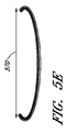
いくつかの実施形態では、心臓弁の接合不全を治療するための接合支援本体であって、心臓弁は、弁面を画定する弁輪と、少なくとも第1の弁尖および第2の弁尖とを有する、接合支援本体が提供され、この接合支援本体は、第1の接合表面と、対向する第2の表面と、第1の側方縁と、第2の側方縁と、下方縁と、上方縁と、弁の弁尖が接合ゾーンに対して接合し得るように構成された、下方縁と上方縁の間で横断方向に延在する第1の接合表面上の接合ゾーンとを備え、第1の接合表面は、50〜60mmの範囲で上方縁から下方縁への全要素アーク長を有し、第1の接合表面は、下方縁と接合ゾーンの間で円錐の表面の一部分に全体的に合致し、第1の接合表面は、円錐の長手方向軸に沿って接合支援本体の下方縁から30〜40mmの範囲内の変曲点で始まる径方向外側へのフレアを備え、この径方向外側へのフレアは5〜12mmの範囲の半径を有する。 In some embodiments, a joint support body for treating heart valve joint failure, wherein the heart valve includes an annulus defining a valve surface, at least a first leaflet and a second leaflet. A bonding support body having a first bonding surface, an opposing second surface, a first side edge, a second side edge, and a lower edge; An upper edge and a joining zone on a first joining surface extending transversely between the lower and upper edges, the valve leaflets configured to be able to join to the joining zone The first joining surface has a total element arc length from the upper edge to the lower edge in the range of 50-60 mm, the first joining surface being part of the conical surface between the lower edge and the joining zone. In general conformity, the first joining surface is 30-40 mm from the lower edge of the joining support body along the longitudinal axis of the cone Comprising a flare radially outward beginning at the inflection point in the range flare to this radially outward has a radius in the range of 5-12 mm.
いくつかの実施形態は、心臓弁の接合不全を治療するための接合支援本体であって、心臓弁は弁輪と第1の弁尖および第2の弁尖とを有し、この第1の弁尖および第2の弁尖は、第1の弁尖と第2の弁尖の第1の接合部のところに第1の交連、および第1の弁尖と第2の弁尖の第2の接合部のところに第2の交連とを有する、接合支援本体を提供し、この接合支援本体は、第1の接合表面と、対向する第2の表面と、第1の側方縁と、第2の側方縁と、下方縁と、上方縁であって、上方曲線の側方余裕部間の距離が第1の交連と第2の交連の距離に等しいように、25〜35mmの範囲の長さを有する曲線を備える上方縁と、接合支援本体の最も近位の範囲と接合支援本体の下方縁の間で弁の弁輪によって画定された弁面に垂直に測定される接合要素長であって、35〜45mmの範囲である接合要素長と、弁輪のレベルと接合支援本体の下方縁の間で弁面に垂直に測定される心室要素長であって、25〜35mmの範囲である心室要素長と、上方縁と下方縁の間の接合ゾーンであって、心臓弁の一般的なレベルにおいて弁面と略平行な接合支援本体の側方縁同士の間で測定される接合ゾーン曲線半径を有し、この接合ゾーン曲線半径が35〜45mmの範囲である、接合ゾーンと、を備える。 Some embodiments are a joint support body for treating heart valve joint failure, wherein the heart valve has an annulus and a first leaflet and a second leaflet, The leaflet and the second leaflet are a first commissure at the first junction of the first leaflet and the second leaflet, and a second of the first leaflet and the second leaflet. A joint support body having a second commissure at a joint of the first joint surface, the joint support body including a first joint surface, an opposing second surface, and a first lateral edge; A range of 25-35 mm such that the distance between the side margins of the upper curve, which is the second side edge, the lower edge, and the upper edge, is equal to the distance between the first commissure and the second commissure. Measured perpendicular to the valve surface defined by the valve annulus between the upper edge with a curve having a length of between the most proximal extent of the joint support body and the lower edge of the joint support body A joint element length, which is in the range of 35-45 mm, and a ventricular element length measured perpendicular to the valve surface between the level of the annulus and the lower edge of the joint support body, Ventricular element length that is in the range of 35 mm and the junction zone between the upper and lower edges, measured between the side edges of the joint support body that are generally parallel to the valve surface at the general level of the heart valve A joining zone having a joining zone curve radius, the joining zone curve radius being in the range of 35 to 45 mm.
いくつかの実施形態では、接合支援本体は、心臓構造内での展開のために第1のアンカーと結合可能な上方縁の中心点の近くに第1の接続要素をさらに備える。いくつかの実施形態は、心室の心臓構造内での展開のために第2のアンカーと結合可能な下方縁に第2の接続要素をさらに備える。 In some embodiments, the joint assist body further comprises a first connecting element near the center point of the upper edge that can be coupled with the first anchor for deployment within the cardiac structure. Some embodiments further comprise a second connecting element at the lower edge that can be coupled with the second anchor for deployment within the cardiac structure of the ventricle.
いくつかの実施形態では、接合支援本体の前面および後面は、ePTFE、ポリウレタンフォーム、ポリカーボネートフォーム、ブタ心膜などの生物組織、またはシリコーンからなる被覆をさらに備える。 In some embodiments, the front and back surfaces of the bonding support body further comprise a coating made of ePTFE, polyurethane foam, polycarbonate foam, biological tissue such as pig pericardium, or silicone.
いくつかの実施形態では、少なくとも1つのストラットが、接合支援本体の形状の維持のために被覆材料内に配設される。いくつかの実施形態では、少なくとも1つのストラットが第2の接続要素に接続され、インプラントの上方縁の方へ延在する。いくつかの実施形態では、ストラットは、ニチノール、ポリプロピレン、ステンレス鋼、または他の任意の適切な材料から構成される。いくつかの実施形態では、ストラットが上方縁の側方余裕部間の距離を維持する助けとなるように、第1のストラットが1つの側方縁の近くの第2の接続から上方縁まで延在し、第2のストラットが第2の側方縁の近くの第2の接続からインプラントの上方縁まで延在する。 In some embodiments, at least one strut is disposed in the coating material to maintain the shape of the bonding assist body. In some embodiments, at least one strut is connected to the second connecting element and extends toward the upper edge of the implant. In some embodiments, the struts are composed of nitinol, polypropylene, stainless steel, or any other suitable material. In some embodiments, the first strut extends from the second connection near one side edge to the upper edge so that the strut helps maintain the distance between the side margins of the upper edge. And a second strut extends from the second connection near the second lateral edge to the upper edge of the implant.
患者の心臓弁の接合不全を治療するための方法であって、心臓弁が弁輪と第1の弁尖および第2の弁尖とを有し、この第1の弁尖および第2の弁尖がそれぞれ近位表面と遠位表面と接合縁と環状縁とを備え、弁輪が弁面をさらに画定し、この弁面が近位方向に心房を、および遠位方向に心室を分離する方法が提供される。いくつかの方法は、心臓組織内で弁輪の遠位に第1のアンカーを選択的に展開することと、第2の弁尖の環状縁の中心点の近くで弁輪の近位に第2のアンカーを選択的に展開することと、接合支援本体が近位方向では心房から、遠位方向では心室まで、弁面を横切って吊設されるように、接合表面と弁尖表面とを備える接合支援本体に第1のアンカーおよび第2のアンカーを結合することとを含む。 A method for treating a joint failure of a patient's heart valve, the heart valve having an annulus, a first leaflet and a second leaflet, the first leaflet and the second valve leaflet. The apex includes a proximal surface, a distal surface, a joining edge and an annular edge, respectively, and the annulus further defines a valve face, which separates the atrium proximally and the ventricle distally A method is provided. Some methods include selectively deploying a first anchor distal to the annulus in the heart tissue and a second proximal to the annulus near the center point of the annular edge of the second leaflet. The joint surface and the leaflet surface so that the anchoring support body is suspended across the valve surface from the atrium in the proximal direction to the ventricle in the distal direction. Coupling a first anchor and a second anchor to a joining support body comprising.
いくつかの方法では、接合支援本体は、接合表面が第1の弁尖と接合するように吊設され、接合支援本体の弁尖表面は、接合不全が軽減されるように第2の弁尖の上に重なる。 In some methods, the joining assist body is suspended such that the joining surface joins the first leaflet, and the leaflet surface of the joining assistance body is the second leaflet so that the joint failure is reduced. Overlapping.
本発明は、概して、改善された医療用デバイス、システム、および方法を提供し、これらは、多くの場合、僧帽弁逆流および三尖弁逆流を含むその他の弁疾患の治療を目的とする。以下の説明は、僧帽弁などの2つの弁尖を有する弁の前尖への言及を含むが、「前尖」は複数の弁尖を有する弁の1つまたは複数の弁尖を指し得ることが理解されよう。たとえば、三尖弁は3つの弁尖を有し、そのため、「前」は内尖、側尖、および後尖のうち1つまたは2つを指し得る。本明細書において説明するインプラントは、概して、弁の弁尖が開放弁構成(弁本体から前尖が分離する)と閉鎖弁構成(前尖が弁本体の対向する面と係合する)との間で交互に切り替わるとき概して血流路に沿った接合支援本体(本明細書では、弁本体と呼ぶこともある)を含む。弁本体は、正常に機能するならば、収縮中に閉塞する弁の区域内の第2の自然(native)弁尖を効果的に交換しながら、自然弁尖の少なくとも1つが接合する表面を設けることによって自然弁尖の接合不全によって引き起こされる間隙をふさぐために自然弁尖の間に配設される。この間隙は、横方向(膨張した左心室および/または僧帽弁輪によって引き起こされ得るなど)および/または軸方向(1つの弁尖が逸脱する、すなわち弁が閉鎖するべきときに流体圧力によって1つの弁尖が押されて弁輪を越えるなど)であってもよい。 The present invention generally provides improved medical devices, systems, and methods, which are often aimed at treating other valve diseases, including mitral and tricuspid regurgitation. The following description includes reference to an anterior leaflet of a valve having two leaflets, such as a mitral valve, although “anterior leaflet” may refer to one or more leaflets of a valve having multiple leaflets. It will be understood. For example, a tricuspid valve has three leaflets, so “anterior” may refer to one or two of the inner leaflet, the side leaflets, and the posterior leaflet. The implants described herein generally have a valve leaflet with an open valve configuration (the front leaflet separates from the valve body) and a closed valve configuration (the front leafe engages the opposing surface of the valve body). It includes a joining support body (sometimes referred to herein as a valve body) generally along the blood flow path when alternating between. The valve body provides a surface to which at least one of the natural leaflets joins, effectively replacing the second native leaflet in the area of the valve that occludes during contraction if functioning normally. In order to close the gap caused by the joint failure of the natural leaflets. This gap is laterally (such as can be caused by an inflated left ventricle and / or mitral annulus) and / or axially (one valve leaflet deviates, i.e., by fluid pressure when the valve should close). For example, one leaflet may be pushed over the annulus).
数ある用途の中でも特に、本明細書において説明する接合補助デバイス、インプラント、および方法は、自然僧帽弁尖の少なくとも1つが密封できる人工の接合ゾーンを作り出すことによって機能的および/または変性僧帽弁逆流(MR)を治療するために構成することができる。本明細書における構造および方法は主に本出願に合うように調整されているが、代替実施形態は、三尖弁、末梢血管系の弁、下大静脈などを含む心臓および/または身体のその他の弁で使用するように構成することができる。 Among other applications, the joining assist devices, implants, and methods described herein provide a functional and / or degenerative mitral by creating an artificial joining zone in which at least one of the natural mitral valve leaflets can be sealed. Can be configured to treat valve regurgitation (MR). Although the structures and methods herein are primarily tailored to fit this application, alternative embodiments include heart and / or other body parts including tricuspid valves, peripheral vascular valves, inferior vena cava, etc. Can be configured for use with any of the valves.
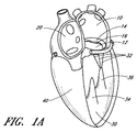
図1A〜図1Dを参照すると、心臓の4つの部屋、すなわち左心房10、右心房20、左心室30、および右心室40が示されている。左心房10と左心室30の間に僧帽弁60が配設される。右心房20と右心室40を分離する三尖弁50、大動脈弁80、および肺動脈弁70も示されている。僧帽弁60は、2つの弁尖すなわち前尖12および後尖14から構成される。健康な心臓では、2つの弁尖の縁が接合ゾーン16において収縮中に並置される。
Referring to FIGS. 1A-1D, four chambers of the heart are shown: left
心臓骨格の一部である線維輪120は、前尖12および後尖14と呼ばれる僧帽弁の2つの弁尖への取付けを提供する。弁尖は、腱索32への取付けによって軸方向に支持される。次に、腱は、左心室の乳頭筋34、36の一方または両方に取り付ける。健康な心臓では、腱支持構造は僧帽弁尖をテザーし、弁尖が拡張期中に容易に開くが、心室収縮中に生じる高い圧力に抵抗することを可能にする。支持構造のテザリング(tethering)効果に加えて、弁尖の形状および組織整合性は、効果的な密封または接合を助長する助けとなる。前尖および後尖の先端は漏斗形の接合ゾーン16に沿って一体となり、三次元接合ゾーン(CZ)の横断面160が図1Eに概略的に示されている。
僧帽弁前尖と僧帽弁後尖は形状が異なる。前尖は、中心線維体(心臓骨格)の上にある弁輪に、後尖よりしっかり取り付けられ、後尖よりやや硬い。後尖は、より可動性の高い僧帽弁輪の後部(posterior mitral annulus)に取り付けられる。閉鎖区域の約80パーセントは前尖である。交連110、114に隣接して、弁輪120上に、または弁輪120の前方に、僧帽弁輪が大動脈の無冠尖の基部と融合するところに形成される左(外側)線維三角124および右(中隔)線維三角126が存在する(図1F)。線維三角124、126は、中心線維体128の中隔および外側の範囲を形成する。線維三角124、126は、いくつかの実施形態では、1つまたは複数の環状または心房アンカーとの安定した係合のための堅いゾーンを提供するので、利点を有することがある。弁尖12と14の間の接合ゾーンCLは、単純な線ではなく、むしろ湾曲した漏斗形の表面インターフェースである。第1の交連110(外側または左)および第2の交連114(中隔または右)は、弁輪120で前尖12が後尖14と合わさるところである。図1C、図1Dおよび図1Fの心房からの軸方向図で最もよく分かるように、接合ゾーンの軸方向断面は、弁輪の重心CAからならびに拡張期中に弁を通る開口部COから分離した湾曲した線CLを全体的に示す。さらに、弁尖縁は波形であり、前尖に比べて後尖の方が切れ込みが大きい。これらのA−P(anterior−posterior)セグメント対、A1/P1、A2/P2、およびA3/P3のうちの1つまたは複数の間で接合不全が生じる場合があり、したがって、接合不全の特性は、接合ゾーンの曲線CLに沿って変化することがある。
The mitral valve leaflet and the mitral valve leaflet have different shapes. The anterior leaflet is attached to the annulus above the central fibrous body (heart skeleton) more firmly than the posterior leaflet and is slightly stiffer than the posterior leaflet. The posterior leaflet is attached to the posterior part of the more mobile mitral annulus. About 80 percent of the closed area is the anterior leaflet. A left (outer) fiber triangle 124 formed on the
次に図2Aを参照すると、心臓の正常に機能する僧帽弁60は拡張期中に開き、血液は左心房から左心室30の方へ流路FPに沿って流れ、それによって左心室を充満させることができる。図2Bに示すように、機能する僧帽弁60は閉鎖し、収縮期中に心室圧の増加によって最初は受動的に、次に能動的に、左心房10から左心室30を効果的に密封し、それにより左心室を囲む心臓組織が収縮することによって血液は血管系全体に前進することができる。
Referring now to FIG. 2A, the normally functioning
図3A〜図3Bおよび図4A〜図4Bを参照すると、僧帽弁の弁尖縁が十分に並置できず、それによって血液が収縮期に心室から心房に逆流するいくつかの状態または疾患状態がある。特定の患者の具体的な病因に関係なく、心室収縮中に弁尖が密封できないことは接合不全として知られており、僧帽弁逆流を引き起こす。 Referring to FIGS. 3A-3B and 4A-4B, there are several conditions or disease states in which the mitral valve leaflets cannot be sufficiently juxtaposed, causing blood to flow back from the ventricle to the atria during systole. is there. Regardless of the specific etiology of a particular patient, the inability to seal the leaflets during ventricular contraction is known as zygosity and causes mitral regurgitation.
概して、接合不全は、一方または両方の弁尖の支持構造による過度のテザリングまたは支持構造の過度の伸長もしくは断裂から生じることがある。その他の一般的でない原因としては、心臓弁の感染症、先天性異常、および外傷がある。図3Aに示すように、弁の機能不全は、僧帽弁逸脱として知られる腱索の伸長から、また場合によっては、動揺弁尖(flail leaflet)220として知られる腱215または乳頭筋の断裂から生じることがある。または、弁尖組織そのものが重複する場合、弁が逸脱することがあり、その結果、心房へと生じる接合のレベルが高いほど、心室収縮期230中に心房内での弁の開口が大きくなる。弁尖のどちらか一方が逸脱したり動揺したりすることがある。この状態は、弁変性による僧帽弁逆流として知られることもある。
In general, joint failure can result from excessive tethering or excessive extension or tearing of the support structure of one or both leaflets. Other uncommon causes include heart valve infections, congenital abnormalities, and trauma. As shown in FIG. 3A, valve dysfunction may result from elongation of the chordae known as mitral valve prolapse, and in some cases from rupture of the
図3Bに示すように、過度のテザリングでは、弁輪の拡大または弁輪の形状変更、いわゆる弁輪拡大240のために、正常な構造の弁の弁尖が適切に機能しない場合がある。このような機能的僧帽弁逆流は、一般に心筋障害および付随する心室拡張に起因する。また、機能的僧帽弁逆流から生じる過度な量の荷重そのものが心不全、心室拡張、弁輪拡大を悪化させ、したがって僧帽弁逆流を悪化させることがある。
As shown in FIG. 3B, excessive tethering may cause the valve leaflets of a normal structure to not function properly due to annulus enlargement or annulus shape change, so-called
図4A〜図4Bは、機能的僧帽弁逆流(図4A)および弁変性による僧帽弁逆流(図4B)における収縮期中の血液の逆流BFを示す。図4Aの弁輪の大きさの増加が心室320および乳頭筋330の肥大によるテザリングの増加と結び付けられることによって、前尖312と後尖314が並置することが防止され、それによって接合が防止される。図4Bでは、腱215の断裂によって、左心房内への後尖344の上方への逸脱が引き起こされ、これによって前尖342に対する並置が防止される。いずれの状況でも、結果は心房内への血液の逆流であり、これによって、左心室圧迫の有効性が低下する。
4A-4B show blood BF during systole during functional mitral regurgitation (FIG. 4A) and mitral regurgitation due to valve degeneration (FIG. 4B). 4A is associated with increased tethering due to hypertrophy of
次に図5A〜図5Bを参照すると、機能的僧帽弁逆流(図5A)および弁変性による僧帽弁逆流(図5B)における接合強化要素500の一実施形態を見ることができる。要素は、この実施形態では、後尖514、腱、および乳頭筋の上にあるように展開されてよい。この実施形態では、要素は、環状アンカー546および心室アンカー556を介して、上方から弁輪540の後面に、および下方から左心室550の後面に取り付けられる。他の実施形態では、複数の環状アンカーおよび/または複数の心室アンカーは、接合強化要素を取り付けるために使用することができる。いくつかの要素では、1つまたは複数の環状アンカーは、1つまたは複数の心房アンカーまたは心耳アンカーによって置き換えられてもよいし、これらで補われてもよい。接合要素は、後弁輪の上方表面、心房後壁、または弁輪自体に取り付けることができる。接合ゾーン516は、インプラント500と自然前尖512の間に確立されている。弁尖接合の失敗は、機能不全の背後にある機序に関係なく、機能的僧帽弁逆流と弁変性による僧帽弁逆流(MR:mitral valve regurgitation)の両方で発生するので、類似のインプラントは、この両方において使用することができる。したがって、図5C〜図5Dに示されるように、自然前尖512が、適切に確立された接合点510で接合要素と並置され、心室の収縮中の血液の流れFを妨げるように、異なる大きさを有する接合強化要素を留置することができる。これを実現するために、さまざまな大きさのインプラントが提供され、異なる寸法は、さまざまな解剖学的構造に適合するように構成される。たとえば、弁の弁輪によって画定された平面に基本的に垂直な平面内で上方環状取付け部位540から下方心室取付け部位550へと測定するインプラント高530と、接合点510と上方取付け部位540の間のインプラント深度520と、接合点のレベルの後壁と接合点の間のインプラント突出部560が存在し得る。図5E〜図5Fの軸方向図に示されるように、一般的には機能的MRよりも大きい、接合強化要素の内側−外側直径570も存在する。図6A〜図6Bに示されるように、拡張期中に、自然前尖の移動によって弁が開く間、インプラント500はほぼ同じ位置に留まることができ、最小限の制限で左心房から左心室への血液の流れFを可能にする。いくつかの実施形態では、アンカーが動かないままの間、インプラント500の表面は、心室収縮期中に膨らむかまたは上方に伸びてもよい。これは、収縮期中に要素の前面または接合表面と接合ゾーンにおける自然弁尖との間で密封を強化するので、有利な場合がある。拡張期中に、表面は、より遠位方向に存在する初期位置に戻ることがある。これは、拡張期中に心房と心室の間の改善された血流路を提供し、接合支援要素を越えた心房からの流出を改善することができる。
Referring now to FIGS. 5A-5B, one embodiment of a
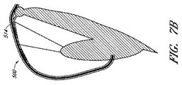
図5および図6は、自然後尖が所定の位置に残され、インプラントが後弁輪または隣接する心房壁に上方から取り付けられる接合強化要素の一実施形態を示す。多数の可能な代替実施形態は、異なる取付け機構を有することができる。たとえば、図7Aでは、後尖は存在せず、外科的に、または疾患の結果、取り除かれている。図7Bでは、自然弁尖は、接合本体の後面に取り付けられる。図7Cでは、接合要素は、弁輪または心房壁ではなく後尖514の前面に取り付けることができる。これらは、変形形態のいくつかの例であるが、他の変形形態も企図される。たとえば、アンカリング構造(図示せず)は、接合要素から心房壁を通って冠状静脈洞へと通過することができ、このアンカリング構造は、冠状静脈洞内の嵌合構造に取り付けられる。または、アンカリング構造は機械的構造であっても単純な構造であってもよく、心房壁を通過し、結び目またはクリップなどの機械的要素によって心臓の心外膜表面上に留めることができる。同様に、下方からの取付けは、心室筋に対してであってもよいし、心尖を通って心外膜または心膜内へと入り、外部から固着されてもよいし、代替取付け手段を使用して他の取付け部位においてであってもよい。
FIGS. 5 and 6 illustrate one embodiment of a joint reinforcement element in which the natural posterior leaflet is left in place and the implant is attached to the posterior annulus or adjacent atrial wall from above. Many possible alternative embodiments can have different attachment mechanisms. For example, in FIG. 7A, the posterior leaflet is not present and has been removed surgically or as a result of disease. In FIG. 7B, the natural leaflet is attached to the rear surface of the bonded body. In FIG. 7C, the joining element can be attached to the front surface of the
本明細書において説明する展開した接合支援インプラントは、いくつかの望ましい特性を示すことができる。いくつかの実施形態は、(弁輪組織の熱収縮、人工弁輪リングの植え込み、および/または弁面の上もしくは下もしくは冠状静脈洞内もしくは関連血管内へのシンチング機構の留置などによる)僧帽弁輪の再構築に依拠する必要はない。有利には、いくつかの実施形態は、弁尖構造を破壊する必要もなく、僧帽弁尖を共にロックしたり僧帽弁尖を融合したりする必要もない。多数の実施形態では、心室の再構築への依存を回避することができ、植え込み後は、非常に長い疲労寿命をもたらし得る制限された偏位を有する植え込まれた受動的デバイスを示す。したがって、インプラントは、自然心臓(たとえば、心室、僧帽弁輪など)解剖学的構造を無傷のままにしておきながら、後尖全体に固着することができる。 The deployed joint assist implant described herein can exhibit several desirable properties. Some embodiments (such as by thermal contraction of the annulus tissue, implantation of the prosthetic annulus ring, and / or placement of a cinching mechanism above or below the valve surface or in the coronary sinus or related blood vessels) There is no need to rely on the reconstruction of the cap annulus. Advantageously, some embodiments do not need to destroy the leaflet structure and do not need to lock the mitral leaflets together or fuse the mitral leaflets. In many embodiments, dependence on ventricular remodeling can be avoided and, after implantation, shows an implanted passive device with a limited excursion that can result in a very long fatigue life. Thus, the implant can be secured to the entire posterior leaflet while leaving the natural heart (eg, ventricle, mitral annulus, etc.) anatomy intact.
どの弁尖セグメントが接合不全を示すかにかかわらず、僧帽弁接合不全の軽減は効果的であることがある。本明細書において説明する治療では、手技中に再配置可能で、展開完了および/または組織応答の開始もしくは完了後ですら、多くの場合は弁構造を損なうことなく、着脱可能なインプラントを利用する。それにもかかわらず、本明細書において説明するインプラントは、不要であると上記で説明した属性のうちの1つまたは複数に依拠する1つまたは複数の治療法と併用することが可能である。インプラントそのものは、移動、血栓塞栓症、感染症、および/または糜爛を阻止する良性の組織治癒および迅速な内皮化を示すことができる。場合によっては、接合支援本体は内皮化を示さないが、その表面は不活性のままであり、それによっても、移動、血栓塞栓症、感染症、および/または糜爛を阻止することができる。 Regardless of which leaflet segment exhibits zygosity, the reduction of mitral valvular dysfunction may be effective. The treatments described herein utilize removable implants that can be repositioned during the procedure and often do not compromise the valve structure, even after deployment is complete and / or after initiation or completion of tissue response. . Nevertheless, the implants described herein can be used in conjunction with one or more therapies that rely on one or more of the attributes described above as being unnecessary. The implant itself can exhibit benign tissue healing and rapid endothelialization to prevent migration, thromboembolism, infection, and / or wrinkles. In some cases, the junction assisting body does not show endothelialization, but its surface remains inactive, which can still prevent migration, thromboembolism, infections, and / or wrinkles.
図8A〜図8Bは、接合不全を起こしている自然弁尖、僧帽弁の場合は後尖の方へ配設される第1の表面810と、前尖の方へ配設され得る第2の表面820とを備える接合強化要素の一実施形態の2つの図を示す。インプラントの上方縁840は、弁輪または隣接する心房壁の全体的形状に適合するように湾曲してよい。
FIGS. 8A-8B illustrate a
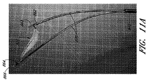
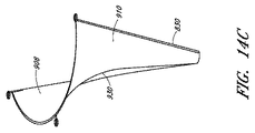
接合支援要素は、心房内の取付け部位と心室内の取付け部位の間で弁を横断し、前尖が接合する接合表面を提供し、後尖を効果的に閉鎖するように、またはこの例では弁尖が取り除かれる、もしくは取り除かれた場合、後尖を置き換えるように心房または弁輪に取り付けられることを可能にする外形を有する。図13A〜図13H、図14A〜図14C、および図15A〜図15Bはその外形を示す。 The joining assist element traverses the valve between the attachment site in the atrium and the attachment site in the ventricle, providing a joining surface where the anterior leaflet joins, effectively closing the posterior leaflet, or in this example The leaflets are removed or have an outline that allows them to be attached to the atrium or annulus to replace the posterior leaflets when removed. 13A to 13H, FIGS. 14A to 14C, and FIGS. 15A to 15B show the outer shape.
図13Aは、環状アンカー部位562と心室アンカーハブ564とを有する接合支援要素500の斜視図を示す。接合支援要素の本体から後方に延在する環状アンカー部位が示されているが、一代替実施形態では、アンカー部位は前面にあってもよい。パッシブまたはアクティブな交連ハブ(commissural hub)880は直径D1を画定することができ、直径D1は、いくつかの実施形態では、自然弁110の第1の側方交連と第2の側方交連の間の距離すなわち交連間距離(ICD:intracommissural distance)に相当することができる。D1は、種々の大きさのインプラントにおいて20〜60mmの範囲であってよく、いくつかの実施形態では、好ましい長さは、最も広範囲の人間僧帽弁ICDに最も密接に相当する35〜45mmの範囲である。
FIG. 13A shows a perspective view of a joining
図13Aは、弁の弁輪によって画定される平面に垂直に測定される心室アンカー部位と心房アンカー部位の距離に相当する接合要素高Hをさらに示す。いくつかの実施形態の接合要素高は30〜80mmであってよく、いくつかの実施形態では、40〜55mmの範囲である。 FIG. 13A further shows a joining element height H corresponding to the distance between the ventricular anchor site and the atrial anchor site measured perpendicular to the plane defined by the valve annulus. In some embodiments, the joining element height may be 30-80 mm, and in some embodiments, in the range of 40-55 mm.
図13Bは、接合要素を、要素の近位から端面図として示す。D1が示されており、弁のレベルで接合要素の内側縁と側方縁の距離を測定する。いくつかの実施形態では、D1は、右線維三角126から左線維三角124までの距離であってよい(図1F)。 FIG. 13B shows the joining element as an end view from the proximal of the element. D1 is shown and measures the distance between the inner and side edges of the joining element at the valve level. In some embodiments, D1 may be the distance from the right fiber triangle 126 to the left fiber triangle 124 (FIG. 1F).
さらに示されているのが、R2の最も後方の点と弁のレベルで接合要素の内側縁と側方縁を結ぶ中心線CLとの間で後側から前側への距離を測定する長さD2である。D2は、約3から約10mmの範囲であってよい。一実施形態では、D2は約6mmであってよい。別の実施形態では、D2は、後弁輪の中心点と前弁輪の中心点の間の距離の約3分の1である。いくつかの実施形態では、D2は、後弁輪の中心点と前弁輪の中心点の間の距離の6分の1から2分の1であってよい。 Also shown is a length D2 measuring the distance from the rear side to the front side between the rearmost point of R2 and the center line CL connecting the inner and side edges of the joining element at the valve level. It is. D2 may range from about 3 to about 10 mm. In one embodiment, D2 may be about 6 mm. In another embodiment, D2 is about one third of the distance between the center point of the rear valve annulus and the center point of the front valve annulus. In some embodiments, D2 may be one-sixth to one-half of the distance between the center point of the rear valve annulus and the center point of the front valve annulus.
図13Bには、接合要素の接合ゾーン曲線半径(すなわち短軸)R2が示されている。短軸は、心臓弁のレベルでの接合要素の横断方向の測定値である。接合ゾーンのレベルでの前面は、インプラントの、収縮期中に前尖が接合する部分である。実施形態における接合ゾーン半径は20〜60mmの範囲であってよく、好ましい接合ゾーン半径の測定値は、好ましくは多種多様の患者測定値に相当する35〜45mmの範囲である。 FIG. 13B shows the bonding zone curve radius (ie, short axis) R2 of the bonding element. The short axis is a transverse measurement of the joining element at the level of the heart valve. The front surface at the level of the joint zone is the part of the implant where the anterior leaflet joins during systole. The joint zone radius in embodiments may be in the range of 20-60 mm, and preferred joint zone radius measurements are preferably in the range of 35-45 mm, corresponding to a wide variety of patient measurements.
接合要素の環状曲線半径R1は、接合要素の近位縁すなわち上方縁の測定値である。いくつかの実施形態では、環状曲線半径は15〜50mmの範囲であってよい。他の実施形態では、R1は25〜35mmであってよい。 The annular curve radius R1 of the joining element is a measurement of the proximal or upper edge of the joining element. In some embodiments, the annular curve radius may be in the range of 15-50 mm. In other embodiments, R1 may be 25-35 mm.
図13Aおよび図13Cはインプラントの略三角形状の実施形態を示しており、したがって、接合インプラントは、上方縁578と、側方縁572および574と、下方縁576とを有し、上方縁578は下方縁576の長さよりも長い長さを有し、その結果、側方縁572と574の間の横断方向距離は、一般にインプラント上で上方から下方へと減少する。たとえば、上方縁長は15〜50mmまたは25〜35mmの範囲であってよいが、下方縁長は1〜15mmまたは2〜6mmの範囲であってよい。
FIGS. 13A and 13C show a generally triangular embodiment of the implant, so that the joint implant has an
図13Dは、接合インプラントの一実施形態の側面図を示す。弁の弁輪によって画定される平面に垂直に測定される接合要素の最も近位の測定値と心室アンカー部位の間の距離に相当する接合要素長L1が示されている。設けられる接合要素長の予想範囲は20〜80mmであってよく、好ましい要素長は、患者の大部分に最も密接に対応する約35から約45mmである。 FIG. 13D shows a side view of one embodiment of a joint implant. Shown is a joint element length L1 corresponding to the distance between the most proximal measurement of the joint element measured perpendicular to the plane defined by the valve annulus and the ventricular anchor site. The expected range of joining element lengths provided may be 20-80 mm, with a preferred element length being about 35 to about 45 mm, which most closely corresponds to the majority of patients.
心室要素長L2も図13Dに示されている。これは、弁の弁輪によって画定される平面に垂直に測定される弁のレベルと心室アンカー部位の距離に相当する。心室要素長の予想範囲は10〜70mmであってよく、好ましい心室要素長の範囲は25〜35mmである。 The ventricular element length L2 is also shown in FIG. 13D. This corresponds to the distance between the valve level and the ventricular anchor site measured perpendicular to the plane defined by the valve annulus. The expected range of ventricular element length may be 10-70 mm, with a preferred ventricular element length range of 25-35 mm.
接合要素長L1および心室要素長L2は、要素長比L2:L1によってさらに説明することができる。実施形態では、この要素長比が、約0.6、0.65、0.7、0.75、0.8、0.85、または0.9であってもよいし、少なくとも約0.6、0.65、0.7、0.75、0.8、0.85、または0.9であってもよいし、0.6、0.65、0.7、0.75、0.8、0.85、または0.9以下であってもよい。 The joining element length L1 and the ventricular element length L2 can be further described by the element length ratio L2: L1. In embodiments, the element length ratio may be about 0.6, 0.65, 0.7, 0.75, 0.8, 0.85, or 0.9, and at least about 0.1. It may be 6, 0.65, 0.7, 0.75, 0.8, 0.85, or 0.9, or 0.6, 0.65, 0.7, 0.75, 0 .8, 0.85, or 0.9 or less.
要素アーク全長L3は、インプラントに沿って測定される接合要素の上方縁から下方縁への測定値である。要素全長は25〜100mmの範囲であってよい。いくつかの実施形態では、L3は約50〜60mmの範囲であってよい。 The element arc total length L3 is a measured value from the upper edge to the lower edge of the joining element measured along the implant. The total element length may be in the range of 25-100 mm. In some embodiments, L3 may range from about 50-60 mm.
以下の表1は、いくつかの実施形態に関する寸法測定値を列2に示し、企図される一実施形態に関する具体的な測定値を列3に示す。
Table 1 below shows dimensional measurements for some embodiments in column 2 and specific measurements for one contemplated embodiment in

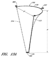
図13Fに示されるようないくつかの実施形態では、接合要素500の外形が円錐の面の一部分にほぼ合致する。実施形態では、心尖602と基部アーク606の間の回転の主軸に沿って約20〜約80mmの範囲内の長さ600と、約25〜約35mmの範囲内の基部アークの半径604が示される。また、基部アークの2つの端の間の直線距離は、約20〜約60mmの範囲内の長さを有する。基部アークの2つの端点は、円錐の面上に存在する。
In some embodiments, as shown in FIG. 13F, the contour of the joining
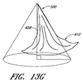
図13Gおよび図13Hに示されるような他の実施形態では、インプラントは、円錐の長手方向軸614に沿って測定される全高608の約50〜約70%にわたって円錐の面の一部分にほぼ合致し、次いで、インプラントは円錐から径方向外側に広がる。その径方向外側フレア612は、約5〜約12mmの範囲内の半径を有すると考えられ得る。フレアが円筒の壁から離れる変曲点610は、長手方向軸に沿って約10〜約70mm距離の範囲内に位置づけることができる。変曲点は、長手方向軸に沿って全長の約45〜約75%のところにあってよい。インプラントは、軸に沿った約25〜約100mmの範囲内の全長も有することができ、基部アークは、約35〜約45mmの範囲内の半径(軸に垂直に測定される)を有することができる。
In other embodiments, as shown in FIGS. 13G and 13H, the implant substantially conforms to a portion of the conical surface over about 50 to about 70% of the
図13Iに示すようなガブリエルのラッパタイプの実施形態では、基部アークの端点を結ぶ線622、620は、ガブリエルのラッパの長手方向軸に垂直であり、長軸から少なくとも約6mmの距離だけ側方にずれていると説明することができる。
In a Gabriel trumpet type embodiment as shown in FIG. 13I, the
図13F〜図13Mによって示されるこれらの実施形態は、インプラントの外形を全体的に説明することを意図する。当業者によって理解されるように、接合要素外形は、この種類のシステムに関して概略的にすることができるが、開示される正確な外形からやや変化する。 These embodiments illustrated by FIGS. 13F-13M are intended to generally describe the outline of the implant. As will be appreciated by those skilled in the art, the joining element profile can be approximate for this type of system, but will vary somewhat from the exact profile disclosed.
別のタイプの実施形態では、インプラントは、図13J〜図13Mに示される構成を有することができる。この構成では、インプラントは、約20〜70mmで、いくつかの実施形態では約25〜35mmの範囲で測定される弁の平面に垂直な平面内で測定される上方縁と心室アンカーの間の全高Hを有する。全体的な要素は、テザー付き心室アンカー866に結合される接合強化要素を備える。
In another type of embodiment, the implant can have the configuration shown in FIGS. 13J-13M. In this configuration, the implant is about 20-70 mm, and in some embodiments, the total height between the upper edge and the ventricular anchor measured in a plane perpendicular to the plane of the valve measured in the range of about 25-35 mm. H. The overall element comprises a joint reinforcement element that is coupled to a
この実施形態では、接合要素はほぼ六角形状をとり、テザー接続864は、接合要素の下表面764から心室アンカー866および心室アンカーハブ864に及ぶ。側方縁572、574は、上方縁578から接合ゾーン920を通って上方縁578にほとんど垂直に走行する。これによって、自然弁尖が接合する広い表面が設けられる。ほぼ接合ゾーンのレベルでは、または接合ゾーンのレベルの下方では、側方縁572、574は下方縁576に向かって収束し、したがって、側方縁572と574の距離は、下方縁576の近位から遠位に向かって減少する。したがって、インプラントは、要素が心室において小さい輪郭を有するように、接合ゾーンの遠位に比較的小さい輪郭を提示する。この構成では、接合要素は、収縮期にインプラントを望ましくなく変形させることができる心室乳頭筋との干渉を回避するように構成される。そのうえ、要素は、心室内での血流のひずみを引き起こす可能性が低い。心室アンカー866は、後壁上で乳頭筋間に留置するように設計される。
In this embodiment, the joining element has a generally hexagonal shape and the
いくつかの実施形態では、テザー782は、2〜30mmの範囲の接合要素の下方縁576間の長さL5を有し、いくつかの実施形態では、テザー長L5は約10〜20mmである。764における近位取付けは、ハブ、アイレット、または他の任意のテザー部位に対するものであってよい。いくつかの実施形態では、テザー782は、長手方向ストラット830のうち1つまたは複数の拡張部を備えることができる。心室アンカーハブ764へのテザー782の遠位取付けは、図示のように、アパーチャを通ってよい。テザー782は、心室アンカーハブ864に取り付けられてもよいし、任意の適切な手段によって取り付けられてもよい。テザー長L5は、要素にかかる張力が患者の解剖学的構造、心室アンカー留置、またはこの両方に基づいてカスタマイズ可能であるように、植え込みの前または後のどちらかで調整可能であってよい。あるいは、テザーは、心室アンカーまたはアンカリング要素に直接取り付けられてよい。テザーは、縫合糸、可撓性材料、ニチノール、金属、またはプラスチックなどの任意の適切な材料からなってよい。テザーは、心室収縮期中に長くなることを可能とするのに十分な弾性を有し、接合強化要素が上方に膨らむ助けとなる材料からなってよく、これによって、接合ゾーン920が自然弁尖をより厳密に模倣することが可能になり、残りの自然弁尖と接合強化要素の接合を強化することができる。
In some embodiments, the
上方縁と側方縁が収束し始める点との間で測定される接合ゾーン長L4は、インプラントの面に面した、前尖と弁尖の間の十分な接合ゾーンを提供し、5〜30mm、好ましくは約15〜25mmの長さL4を有するように構成される。上記で説明したように、側方縁562、564は、自然弁尖が接合する広い表面を提供するために、距離L4にわたって上方縁568に対して略垂直に延在することができる。上方縁によって示され、L4に相当する高さと上方縁と基本的に平行な下方境界とを有する接合強化要素の近位接合部分は、拡張期で少なくともその緩和位置にある間に弁面に基本的に垂直な方向に略下方に延在してもよいし、凸状の前側(接合表面上の)曲線を示してもよい。他の実施形態に関して説明したように、要素のこの近位接合部分も、遠位方向に湾曲する前に弁面と略平行に走行してもよいし、遠位方向に湾曲する前に上方および内側に実際に湾曲してもよい。 The joint zone length L4 measured between the upper edge and the point at which the lateral edges begin to converge provides a sufficient joint zone between the anterior leaflet and the leaflet facing the face of the implant, 5-30 mm. , Preferably having a length L4 of about 15-25 mm. As explained above, the side edges 562, 564 can extend substantially perpendicular to the upper edge 568 over a distance L4 to provide a wide surface to which the natural leaflets join. The proximal joint portion of the joint strengthening element, indicated by the upper edge and having a height corresponding to L4 and a lower boundary essentially parallel to the upper edge, is basically at the valve face while at least in its relaxed position during diastole It may extend substantially downward in a perpendicular direction, or may show a convex front curve (on the bonding surface). As described with respect to other embodiments, this proximal interface portion of the element may also run generally parallel to the valve face before bending in the distal direction, and upward and before bending in the distal direction. It may actually be curved inward.
インプラント幅D1は、いくつかの実施形態では、自然弁110の第1の側方交連と第2の側方交連の間の距離すなわち交連間距離(ICD)に相当することができる。D1は、種々の大きさのインプラントにおいて20〜60mmの範囲であってよく、好ましい長さは、最も広範囲の人間僧帽弁ICDに最も密接に対応する35〜45mmの範囲である。
The implant width D1 may correspond to the distance between the first and second lateral commissures of the
図13Jに示されるようないくつかの実施形態では、環状の補強ストラットは、側方縁562、564を越えて延在することができる。これらの実施形態では、三角アンカーアイレット791は、前側線維三角および後側線維三角(図1Fを参照されたい)に固着され得るインプラントの領域に対応する。一般に、三角部は、それぞれの交連に対して約1〜10mm外側または内側に、かつ交連よりも約1〜10mm前方にある。図13Jにおける実施形態は、一体化された環状アンカーアイレット732と三角アンカーアイレット791とを有する環状補強ストラット730を示す。他の実施形態では、アンカーまたはアンカーハブを要素に接続するハブまたはテザーを含む、さまざまな三角アンカー構成は、要素の表面に一体化されたテザー接続されたアイレットの内側端または他の任意の適切な接続手段により、アンカーに接合強化要素の上方縁を接続することができる。
In some embodiments as shown in FIG. 13J, the annular reinforcing struts can extend beyond the side edges 562,564. In these embodiments, the
あるいは、図13Kに示すように、交連アンカーアイレット890が、上方縁の側方縁において外側に設けられてよい。図13Lに示すように、接合強化要素の接合表面は、点793と795の間でインプラントの上方縁から側方に現れ、上方縁と接合ゾーン920の間に示される三日月を有する略弁状平面において比較的平坦な三日月形を形成してもよく、接合表面は、その点において、弁状平面に垂直な平面内で遠位方向に、または弁状平面に垂直な平面に対して径方向外側にすら進んでもよい。いくつかの実施形態では、接合強化要素の接合表面は、上方縁から上方にかつ径方向内側に、遠位方向に進む前に、弁面に垂直な長手方向に、または弁面に対して径方向内側もしくは外側に、進む。
Alternatively, as shown in FIG. 13K, commissure anchor eyelets 890 may be provided on the outside at the side edges of the upper edge. As shown in FIG. 13L, the bonding surface of the bonding reinforcing element appears laterally from the upper edge of the implant between
図14A〜図14Cは、後面910と、前面908と、ストラット830と、接合ゾーン920とを有する接合要素の斜視図を示す。さらに、インプラントの上方縁の中心点で心室ハブから心房/環状ハブまで占めるインプラントの表面に沿った測定値に相当する後尖曲線L3の長軸が、図14Cおよび図15A〜図15Bに示されている。後尖曲線半径R3の長軸の範囲は10〜50mmであってよく、好ましい半径はほとんどの患者に対応する20〜30mmである。後尖曲線の長軸は、心室から乳頭筋、腱索、弁尖自体を通って、後方に弁輪/心房の後壁の方へと至る後尖複合体の経路を全体的に示す。接合要素が後尖の上に留置されるときに自然の解剖学的構造にほぼ対応し、比較的に正常な部屋の大きさおよび外形を維持するために、インプラントの曲線が心室収縮期の終わりでまたはその近くで後尖曲線に概して対応することが重要なことがある。いくつかの実施形態では、インプラントの接合ゾーンが後尖の唇状部と同様に振る舞うように、インプラントの曲線が心周期中に変化する。
14A-14C show perspective views of a joining element having a
図8A〜図8Bおよび図10Aに示されるように、ストラット830は、依然としてインプラントがカテーテルを通る展開のために縮小構成をとることを可能にしながら、留置時にインプラントの形状を維持する助けとなるように、インプラントの長手方向軸と略平行に配置されてよい。ストラットは、放射線不透過性材料から構成されてよい。いくつかの実施形態では、ストラットは、ニチノール合金などの弾性的に変形可能な材料から構成される。他の実施形態では、ストラットは、ステンレス鋼、ポリプロピレン、高密度ポリエチレン(PE:polyethylene)、ダクロン、SISなどの無細胞コラーゲンマトリックス、または他のプラスチックなどを含む他の材料から構成されてよい。他の実施形態では、ストラットは、ePTFE、ダクロン、および/またはポリプロピレンの芯の周囲の高密度PEシースなどの組み合わせであってよい。ストラットは、円形断面を有してもよいし、卵形断面を有してもよいし、リボン状であってもよい。いくつかの実施形態では、ストラットは、コイルばねか、またはジグザグ形である。ストラットは、一定の剛性を有してもよいし、弁本体の環状端では弁本体の心室端よりも剛性であってもよい。弁本体被覆850は、ePTFEなどの材料からなってよい。被覆のための他の材料としては、ポリウレタンフォーム、ポリカーボネートフォーム、ブタ心膜、胸膜、腹膜などの生物組織、シリコーン、ダクロン、無細胞コラーゲンマトリックスなどがある。いくつかの実施形態では、弁本体被覆は、ePTFEによって囲まれたフォーム材料を含むことができる。スポンジ材料またはフォーム材料を使用することによって、カテーテルを通過するのに十分なほど小さい直径にインプラントを折りたたむ機能が向上する。いくつかの実施形態では、弁本体被覆は孔を持たないか、または内皮化および細胞接着を向上させるために微小孔を有してもよい。弁本体はまた、可視性を向上させるために放射線不透過性材料またはエコー増強材料を組み込むことができる。フレームを有する弁本体または支持インターフェースのあらゆる支持構造は、金または白金などの放射線不透過性材料でコーティングしてもよいし、バリウムに含浸させてもよい。弁尖を並置する弁本体要素860は、エコー増強材料でコーティングしてもよい。弁本体要素860は、ヘパリンボンディングまたはキノリン化合物およびキノキサリン化合物などの、血栓症を阻止する材料で、または内皮化を加速する材料で、または感染症を阻止する抗生物質で被覆されてよい。接合支援デバイスは被覆材料の層の間に挟まれたストラットから構成されてよく、このストラットは、両表面上の同じ材料から構成されてもよいし構成されなくてもよい。あるいは、ストラットは、被覆材料の単一層の第1の表面または第2の表面に取り付けられてもよいし、これに埋め込まれてもよく、図10Eに示されるように被覆材料890によって「縫い合わされ」てもよい。これに加えて、またはこの代わりに、接合要素890の上方縁と平行に走行し、上方縁の形状を維持する助けとなる1つまたは複数の支持ストラットが設けられてもよい。
As shown in FIGS. 8A-8B and 10A, the
いくつかの実施形態では、接合要素支持構造は、ステント内で見られ、ePTFE、ダクロン、ブタ心膜などの弁本体被覆によって覆われるものなどの平らな金属メッシュを含む。メッシュは、カテーテルを通って導入されるために折りたたまれる。 In some embodiments, the joining element support structure comprises a flat metal mesh such as that found in a stent and covered by a valve body coating such as ePTFE, Dacron, porcine pericardium. The mesh is folded for introduction through the catheter.
接合支援デバイスの一代替実施形態が図9に示されている。ストラット830は異なる構成で示されており、この構成では、展開時に近位部分の形状を維持する助けとなるように、1つまたは複数が上方縁の方へ側方に湾曲する。この構成には、環状アンカーまたは心房アンカー863に接続するための心房ハブ862と、心室アンカー866に接続するための心室ハブ864も示されている。示されている(portrayed)アイレットおよびハブを含むが、たとえば縫合糸、ステープル、接着剤、またはクリップなどの当業者に知られている他の接続手段も含む代替係合手段が、デバイスを各アンカーに接続するために企図されている。代替実施形態では、アンカーは、デバイスの一体部分を形成することができる。図9の実施形態では、図示の両アンカーは、らせん状のアンカーである。多数の可能なアンカリング手段の構成、アンカーの構造、およびアンカリング手段の設計が存在する。
An alternative embodiment of a bonding assist device is shown in FIG. The
接合補助デバイスまたはインプラントは、デバイスを安定化させる1つまたは複数の心房アンカーおよび/または心室アンカーを含むことができ、アンカーは、任意選択で、重複した固定をもたらす。1つまたは複数の心房アンカーは、弁輪に取り付けるかまたはこれに隣接することができる。弁輪アンカーを含む場合、弁輪アンカーは、さらなる安定性を得ることを目的として、弁輪アンカーの内皮化、任意選択で慢性組織内殖または被包(encapsulation)を促進するためにePTFEまたはダクロンなどの生体適合性材料で覆ってもよい。 The joining assist device or implant can include one or more atrial anchors and / or ventricular anchors that stabilize the device, and the anchors optionally provide overlapping fixation. One or more atrial anchors can be attached to or adjacent to the annulus. When including annulus anchors, the annulus anchors may be ePTFE or dacron to promote endothelialization, optionally chronic tissue ingrowth or encapsulation, for the purpose of obtaining additional stability. It may be covered with a biocompatible material such as.
弁輪アンカーは、周囲組織に短時間固定(acute fixation)するための複数の逆とげを含んでもよい。他の実施形態では、心房アンカーは、僧帽弁の弁輪、心室の組織、および/または心房のその他の組織へのねじ込みまたは係合に適した、複数のらせん、クリップ、銛または逆とげの形をしたアンカーなどを備えてもよいし、または心房アンカーまたは心室アンカーは、細長いアンカー結合本体を介して送達されるRFまたは他のエネルギーを使用した溶接によって組織に取り付けることができる。 The annulus anchor may include a plurality of barbs for short time fixation to surrounding tissue. In other embodiments, the atrial anchor is comprised of a plurality of helices, clips, scissors or barbs suitable for screwing or engaging the mitral valve annulus, ventricular tissue, and / or other tissue of the atrium. A shaped anchor or the like may be provided, or the atrial anchor or ventricular anchor may be attached to the tissue by welding using RF or other energy delivered through an elongated anchor coupling body.
心室アンカーは、弁尖を並置する要素に対して回転可能で縫合糸またはePTFEチューブによって弁尖を並置する要素のハブに接続されるらせんを備えることができる。いくつかの実施形態では、心室アンカーは、弁本体から心室中隔を通って右心室までまたは心尖を通って心外膜もしくは心膜に延在するテザーまたはその他の取付け手段の形で含めることができ、テザーまたはその他の取付け手段は、心内/心外手技(endo/epi procedure)において、心内/心外手技と併用して、心臓の外部から固着することができる。らせん状のアンカーを使用するとき、これらのアンカーは、白金/Ir、ニチノール合金、および/またはステンレス鋼などの生体不活性材料を備えることができる。 The ventricular anchor can comprise a helix that is rotatable relative to the apex element and is connected to the hub of the apex element by a suture or ePTFE tube. In some embodiments, the ventricular anchor may be included in the form of a tether or other attachment means that extends from the valve body through the ventricular septum to the right ventricle or through the apex to the epicardium or pericardium. The tether or other attachment means can be secured from outside the heart in an endo / epi procedure in conjunction with an intracardiac / extracardiographic procedure. When using helical anchors, these anchors can comprise a bioinert material such as platinum / Ir, Nitinol alloy, and / or stainless steel.
前述のように、いくつかの実施形態には、左心耳内に留置するために拡張可能な構造の形をした心房アンカーを含めることができる。さらに他の実施形態では、心房アンカーおよび支持インターフェースは、心房中隔アンカーに取り付けられた可撓性のラインまたはテザーの形で含めることができる。この心房中隔アンカーは、任意選択でよく知られている構造を使用して、経中隔閉鎖デバイスのように構成することができる。あらゆる左心耳アンカーまたは心房中隔アンカーは、ePTFE、シリコーン、ダクロン、または生物組織などの生体適合性材料で覆ってもよいし、またはRF溶接を使用して所定の位置に固定してもよい。左心耳アンカーまたは心房中隔アンカーは、縫合糸またはePTFEチューブによって弁尖を並置する弁本体要素に接続してもよいし、またはニチノール合金などのあらかじめ整形した剛性または弾性の材料を備えてもよい。 As previously mentioned, some embodiments can include an atrial anchor in the form of an expandable structure for placement in the left atrial appendage. In yet other embodiments, the atrial anchor and support interface can be included in the form of a flexible line or tether attached to the atrial septal anchor. This atrial septal anchor can be configured like a transseptal closure device, optionally using well-known structures. Any left atrial appendage or atrial septal anchor may be covered with a biocompatible material such as ePTFE, silicone, dacron, or biological tissue, or may be secured in place using RF welding. The left atrial appendage or atrial septal anchor may be connected to the valve body element apposing the leaflets by a suture or ePTFE tube, or may comprise a pre-shaped rigid or elastic material such as Nitinol alloy. .
次に図10A〜図10Eを参照すると、接合要素のさらなる略図が示されている。図10Aには、代替アンカー実施形態を有するデバイス100が示されており、この実施形態では、アクティブならせん状心房アンカー863およびアクティブならせん状心室アンカー866がデバイスに結合される。しかし、パッシブな側方交連アンカー880も示されており、インプラントが心臓内で展開されるとインプラントの形状および位置を維持する助けとなることができる。
Referring now to FIGS. 10A-10E, a further schematic illustration of the joining element is shown. FIG. 10A shows a
あるいは、図10Dおよび図10Eに示すように、アイレット884またはハブを介してアクティブアンカー886と係合するように構成され得る結合機構がデバイスの心房部分の一方または両方の交連面上に存在してもよい。同様に、いくつかの実施形態では、要素の湾曲を維持する助けとなるために、要素の環状余裕部に沿って支持体が留置されてもよい。
Alternatively, as shown in FIGS. 10D and 10E, there is a coupling mechanism on one or both commissural surfaces of the atrial portion of the device that can be configured to engage the active anchor 886 via an
図10Bには、1つの可能な骨組み構造が示されており、ニチノールストラット830は、心房アイレット862と心室ハブ864を接続する。たとえば、図8および図9に示すように、他のストラットが被覆に組み込まれてもよい。これらのストラットは、別個であってよいし、心室ハブに組み込まれてもよいし、互いと一体化して骨組みを形成してもよい。ストラットは、任意の数の方法で、インプラントの所望の形状および湾曲を維持する助けとなるような形状をしてよい。図8および図9は2つの変形形態を示しているが、多くの他の変形形態を企図することができ、当業者には明らかである。
In FIG. 10B, one possible skeletal structure is shown, where the
図10Dおよび図10Eは、ニチノールケーブルまたは変形可能なプラスチックなどの材料を含む環状リング890が、接合要素の上方縁に、またはその近くに、かつ同じ平面内に留置される別の実施形態を示す。いくつかの実施形態では、この環状リングは、アクティブな交連アンカー用のハブまたはアイレット884内で側方に終端することができ、他の実施形態では、パッシブアンカー内で側方に終端することができる。このように企図された環状リングは、接合支援要素の所望の近位外形を維持する際の支援を提供する。環状リングは、たとえば、平面状であってもよいし、自然弁弁輪の三次元形状に対応するようにサドル形であってもよい。
FIGS. 10D and 10E show another embodiment in which an
次に図10Fを参照すると、接合要素500は、後尖16に機能的に置き換わるように、心臓の中で展開されると心室アンカー866を介して血流路に沿って僧帽弁の遠位に取り付けられ、弁を横断し、心房内で近位方向に取り付けられる。後尖16は要素によって覆われてもよいし、部分的または完全に除去されてもよく、要素は前尖に接合し、接合ゾーンから環状リングの周囲までの後方からの被覆性を提供する。接合要素は、心周期中に周囲の心臓構造が互いに対して移動するとき、何らかの動きおよび変形を経験することが企図されている。しかし、デバイス上の繰返し応力は、その位置が比較的動かないことによって最小に抑えられ、経時的な疲労の可能性を減らし、インプラントの寿命を最大にする。被覆および枠において使用される材料は、これを考慮して選定されてよい。
Referring now to FIG. 10F, the
要素に対する前尖の接合が心房と心室の連通を閉鎖し、したがって、閉鎖に後尖を関係させることなく、接合不全を軽減し、僧帽弁逆流を最小に低下させるまたは完全になくすように、弁のレベルから近位方向に後尖を覆うことが望ましいことがある。接合要素は、前面と後面の間で細長くて狭く、最小の空間を占有し、血液が一方の側から他方の側へ、さらに要素の両側面を超えて移動することを可能にすることができるので、心室内での血液の比較的正常な循環を可能にするように設計することができる。図13A〜図13Cに見られるように、ニチノール、ステンレス鋼、または他の適切な材料から作製されるストラットは、インプラントの外形を維持し、心臓内での長期植え込みおよび前尖に対する接合に最も適した多種多様の被覆材料のいずれかを選定することを可能にすることを実質的に助けることができる。 So that the junction of the anterior leaflet to the element closes the communication between the atrium and the ventricle, thus reducing zygosity and minimizing or completely eliminating mitral regurgitation without involving the posterior leaflet in the closure. It may be desirable to cover the posterior leaflet proximally from the level of the valve. The joining element can be elongated and narrow between the front and back surfaces, occupying minimal space and allowing blood to move from one side to the other and beyond both sides of the element. So it can be designed to allow a relatively normal circulation of blood in the ventricle. As seen in FIGS. 13A-13C, struts made from nitinol, stainless steel, or other suitable material maintain the shape of the implant and are best suited for long-term implantation in the heart and bonding to the anterior leaflet It can substantially help to make it possible to select any of a wide variety of coating materials.
次に図11A〜図11Bおよび図12A〜図12Cを参照すると、心室アンカー866と係合する心室ハブ864と環状アンカー863と係合する環状アイレット862とを有する接合支援デバイス500の一実施形態が示されている。各アンカーは、その近位端にドライバ870によって係合され得る。図11A、図11B、および図12Bでは、留置カテーテル872から出現するドライバが見られる。いくつかの実施形態では、デバイスは体外で組み立てられ、アンカーをデバイスに、さらにドライバをアンカーに係合することが可能であることが分かる。次に、ドライバをカテーテル内へと引っ込めることができ、図12Aで500と示されるように、デバイスはその折りたたみ位置にある。ドライバは、アンカーを適切な位置に留置するように外科医によって別個に操作されてよい。あるいは、アンカーは、カテーテルを通しての展開の前またはその後に、デバイスおよび/またはドライバに順次係合されてよい。図11Cは、接合要素が収縮期中に前尖12と接合し、自然前尖によって、環状リングにおける弁密封を維持するように、後尖14を完全に覆う、留置後の接合要素を示す。
Referring now to FIGS. 11A-11B and FIGS. 12A-12C, an embodiment of a
接合支援要素の別の実施形態が、図11C〜図11Eで見ることができる。この実施形態では、いくつかの接合要素ストラット830が、インプラントの下方縁576から長手方向軸に沿って走行する。ストラットは、互いに、または心室ハブに下方に接続することができる。あるいは、図11C〜図11Eに示されるように、ストラットは、心室アンカー綿撒糸762に接続することができる。各ストラットは、要素の被覆内で下方に終端することができる。各ストラットは、単一の長手方向要素を備えてもよいし、折り曲げられて2つ以上のストランドを構成してもよい。図11C〜図11Eに示すように、単一のストラットは、インプラントの上面の方へループを作るニチノールワイヤまたは他の材料のストランドからなることができる。このループ区域は、図に示すように、環状アンカーアイレット732のためなどの被覆材料の中断の周囲の補強を提供することができ、このループ区域から、直接的に、またはテザーおよび取り付けられているハブなどの1つもしくは複数の介在接続構造によって、アンカーを展開することができる。ストラット830は、図示のように比較的均等に離隔されるように留置されてもよいし、中心または側方縁572、574の方へ1点に集められてもよい。環状アンカーアイレットは、僧帽弁輪、左心房、左心耳、または線維三角の一方の中へと展開され得るアンカーまたはアンカリング要素と結合可能であってよい。
Another embodiment of a joining aid element can be seen in FIGS. 11C-11E. In this embodiment, several joining element struts 830 run along the longitudinal axis from the
いくつかの実施形態では、たとえば接合ゾーンの近くで追加補強を提供するために長手方向に配向されたストラットのうち2つ以上を接続する横断方向ストラットが存在し得る。追加の環状補強ストラット730は、要素の上方縁578に、またはその近くに設けられてよい。これは、側方縁572、574で、またはその近くで終端してもよいし、1つまたは複数の交連アンカーの一部として越えてもよい。
In some embodiments, there may be transverse struts connecting two or more of the longitudinally oriented struts, for example, to provide additional reinforcement near the joining zone. Additional
環状補強ストラット730は、カテーテルを介した送達のためにより容易に小型化されるように、1つまたは複数の長手方向ストラット830と接続されてもよいし、図示のように、被覆材料内で上方に留置されてもよい。これは、環状補強ストラット730が弁輪または心房に対するテザリングを補強する場合、インプラントに耐久性の向上を提供することもできるが、長手方向ストラットは、心室収縮期中に接合要素の本体が上方向に膨らむかまたは伸びる間の支持を提供し、収縮期中は互いから側方にやや離れて、拡張期中は互いの方へ移動する機能の向上を有することができる。横断方向環状補強ストラット730と長手方向ストラット830の分離を維持することにより、接合ゾーンを通るインプラントの上方部分が収縮期中に自然弁尖の動きをより厳密に複製し得るように、長手方向ストラットの上方縁と環状補強ストラットの間で上方回転を可能にすることによって、接合強化インプラントの機能も改善され得る。上方リムが長手方向ストラットに直接接続されて枠を形成する比較的に剛性の構成物により、インプラントの表面が移動するたびに支持環状補強ストラットが移動しなければならないので、インプラント寿命が減少し、自然弁尖と接合要素の接合は、心周期中に何らかの移動を有する要素によって最適化されないことがある。そのうえ、長手方向ストラット830の上方縁の近くで始まる1つまたは複数の環状アンカーアイレット732の使用は、環状補強ストラットに接続されてもされなくてもよい1つまたは複数の交連アンカーに加えて、またはその代わりに、達成されてよい。
Annular reinforcing
環状補強ストラットは、図11C〜図11Eでは交連アイレット734の近くで終端するように示されている。1つまたは複数のアイレット開口部734のそれぞれは、環状補強ストラットのループによって形成されてもよいし、環状補強ストラット730と別であってもよい。アイレットは、直接的に、テザー構造を介して、または他の手段を介して、アンカーまたは環状アンカーハブ736に接続されてよい。いくつかの実施形態では、環状補強ストラット730内の局所的なループは、環状アンカーアイレット732を囲み、画定することができる。
The annular reinforcing struts are shown terminating in the commissure eyelets 734 in FIGS. 11C-11E. Each of the one or more eyelet openings 734 may be formed by an annular reinforcing strut loop or may be separate from the annular reinforcing
図11C〜図11Eのインプラントは、心室アンカーと接合強化要素の間の接続の手段として心室アンカー綿撒糸762を備えることができる。心室アンカー綿撒糸は、図示のように略長方形の形状であってもよいし、正方形または丸くてもよいし、楕円形であってもよいし、他の任意の好都合な形であってもよい。綿撒糸は、当業者に知られているいくつかの適切な材料のいずれか1つからなってよい。いくつかの例では、組織の内方生長を促進し、接合インプラントの患者の組織への接続を強化する材料を使用することが有利なことがある。他の実施形態では、ePTFE、VTFE、PTFE(ポリテトラフルオロエチレン)、テフロン、ポリプロピレン、ポリエステル、ポリエチレンテレフタレート、または任意の適切な材料などの組織の内方生長を阻害するまたはこれに対して不活性である材料が好ましいことがある。いくつかの実施形態では、コーティングは、組織の内方生長を阻害するまたは促すために綿撒糸上に置かれてもよい。1つまたは複数のアンカーは、適切な位置で綿撒糸の材料を貫通し、基盤となる心組織に綿撒糸を固着することができる。したがって、いくつかの実施形態では、綿撒糸は、構造メッシュ、フェルト、または帯ひも(webbing)などの容易に穿刺される材料を含むことができる。 The implants of FIGS. 11C-11E can include a ventricular anchor pledget 762 as a means of connection between the ventricular anchor and the joint reinforcing element. The ventricular anchor pledget may be generally rectangular as shown, square or round, oval, or any other convenient shape. Good. The pledget may consist of any one of several suitable materials known to those skilled in the art. In some instances, it may be advantageous to use materials that promote tissue ingrowth and enhance the connection of the joint implant to the patient's tissue. In other embodiments, inhibits or is inactive against tissue ingrowth such as ePTFE, VTFE, PTFE (polytetrafluoroethylene), Teflon, polypropylene, polyester, polyethylene terephthalate, or any suitable material. A material may be preferred. In some embodiments, the coating may be placed on the pledget to inhibit or promote tissue ingrowth. One or more anchors can penetrate the pledget material at an appropriate location to secure the pledget to the underlying heart tissue. Thus, in some embodiments, the pledget can include an easily pierced material such as a structural mesh, felt, or webbing.
図11Eは、長手方向ストラット830が環状アンカーアイレット732、環状補強ストラット732、交連アンカーアイレット734、および交連アンカーハブ736を有するループ内の上方で終わる接合要素500を示す。下方では、インプラント768に遠位方向に結合された心室綿撒糸762が示されている。縫合糸、ワイヤ、被覆の層への組み込み、リベットの留置、または他の手段を含む結合の任意の手段が使用されてよい。デリバリーカテーテル930から出現し、綿撒糸762を貫通する心室アンカー866が見られる。
FIG. 11E shows a joining
インプラントの外形によって、限られた数のインプラントの大きさが広範囲の患者測定値を包含することが可能になる。そのうえ、外科医による測定は、手術前に、または手術中にすら、比較的容易に行うことができる。心エコー図を介して得られる2つの測定は、適切なインプラントの大きさを決定するために使用することができる。図16A〜図16Bに示すように、弁の端面図では、交連間距離ICDの測定が可能であり、後尖930の長軸の測定は、心エコー図に関する軸方向図を取得しながら実行することができる。これらの2つの測定をガイドとして使用して、接合支援要素からの適切な選択を実行することができる。あるいは、適切な大きさにされたインプラントの選択をガイドするために、他の測定を組み合わせて使用することができる。心エコー図に加えて、X線、CT、心臓鏡、またはMRIを使用して、測定値を得ることが可能なことがある。心エコー図は、経胸壁ルート、経食道ルート、または心腔内ルートを介して記録することができる。インプラントの構成およびそのアンカリング方法に応じて適切な撮像手法および像の角度が使用されることが当業者には理解されよう。
The implant geometry allows a limited number of implant sizes to encompass a wide range of patient measurements. Moreover, measurements by the surgeon can be made relatively easily before surgery or even during surgery. Two measurements obtained via echocardiogram can be used to determine the appropriate implant size. As shown in FIGS. 16A to 16B, in the end view of the valve, the intercommissural distance ICD can be measured, and the major axis of the
本明細書において説明する接合補助デバイスは、低侵襲性手術(たとえば開胸術、経心尖的に(transapically)、左心耳(LAA)を介して、右肺静脈を介して、他の左心房切開術など)による経血管的(transvascular)送達および/または展開のために構成されることが多く、送達および留置は、好ましくは、心臓弁の自然弁尖間に、または心臓弁の自然弁尖に隣接して行われる。具体的には、弁は、三尖弁および/または僧帽弁などのAV弁のうちの1つとすることができる。図面およびいくつかの実施形態は主に僧帽弁に関連するが、類似の方法およびデバイスを三尖弁に適用することができる。インプラントの接合補助本体は、多くの場合、デリバリーカテーテルによって送達することができ、小さな輪郭から、弁の自然弁尖間の留置に適した寸法に対する大きな輪郭に拡張することが可能な場合がある。いくつかの実施形態では、インプラントは、(たとえば弁の置換後の)非自然(non−native)弁の治療のための、または以前に自然弁尖を外科的に変更した後での治療のための適用例を見出すこともできる。 The joining assist devices described herein can be used for minimally invasive surgery (eg, thoracotomy, transapically, via the left atrial appendage (LAA), via the right pulmonary vein, and other left atrial incisions. Often configured for transvascular delivery and / or deployment by surgery, etc., and delivery and placement is preferably between the natural leaflets of the heart valve or to the natural leaflets of the heart valve Done adjacent. Specifically, the valve can be one of AV valves such as a tricuspid valve and / or a mitral valve. Although the drawings and some embodiments relate primarily to the mitral valve, similar methods and devices can be applied to the tricuspid valve. The implant assisting body of the implant can often be delivered by a delivery catheter and can be expanded from a small profile to a large profile for dimensions suitable for placement between the natural leaflets of the valve. In some embodiments, the implant is for treatment of a non-native valve (eg, after replacement of a valve) or for treatment after a prior surgical change of the natural leaflet. Application examples can also be found.
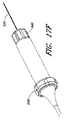
次に植え込みに関して、接合支援要素は、デリバリーシステムを利用する低侵襲性技法または経カテーテル的技法によって植え込まれ得る。図16Cに示すように、デリバリーシステムはデリバリーカテーテル930を含むことができ、このデリバリーカテーテルは、少なくとも1つの貫通内腔を有する可変の剛性シャフトを備え、このシャフトは、少なくとも遠位部932に沿って偏向するように構成される。デリバリーカテーテルの偏向は、カテーテルシャフトを通って偏向ゾーンに延在する細長いプルワイヤを介して、カテーテル偏向またはスリーブ制御ノブ938によって制御されてよい。デリバリーカテーテルは、デバイスアンカー866、886を操作し、かつデリバリーカテーテルとのデバイスのドッキングおよびドッキング解除を操作する制御ハンドル934をさらに含むことができる。この制御ハンドルは、システムから空気を除去し、植え込みの部位への生理食塩水または造影剤などの流体の注入ならびにデリバリーカテーテル930の遠位面から心腔内電位図を監視および記録するための電気信号接続を可能にするために、洗浄ポート、灌注ポート、および/または吸引ポートをさらに含むことができる。
With respect to implantation, the joining support element can then be implanted by minimally invasive or transcatheter techniques that utilize a delivery system. As shown in FIG. 16C, the delivery system can include a
デリバリーシステムは、デバイスアンカーを操作し、アンカーをデリバリーカテーテルに最初に展開してデリバリーカテーテルから捕捉し、最初に展開したアンカーのうちの1つまたは複数に弁本体を遠位方向に案内するための、少なくとも1つのトルクシャフトまたはその他の細長いアンカー結合本体も含むことができる。結合本体は、アクティブアンカー制御ノブ940によって制御されるドライバシャフト870であってよい。さらに、アンカーおよび/または接合本体は、テザー950を介してデリバリーシステムに接続されてよく、これによって、インプラントの位置および機能を試験しながらアンカーまたはデバイスの展開後に接続を維持することが可能になる。テザーによって、インプラントは、留置が最初は最適でない場合デリバリーシステムに再固着することができ、再調整が可能になる。テザーを維持および操作するために、テザー制御ノブ942が制御ハンドル上に設けられてよい。
A delivery system for manipulating a device anchor, initially deploying and capturing the anchor from a delivery catheter, and guiding the valve body distally to one or more of the initially deployed anchors , At least one torque shaft or other elongated anchor coupling body may also be included. The coupling body may be a
デリバリーシステムは、外側シースまたはイントロデューサも含むことができ、これは通常、外側シースの内腔を通して左心房にデリバリーカテーテルを導入することを可能にし、したがって外側シースは経中隔シース944として働く。この経中隔シースは、腔の少なくとも1つを有する可変剛性の外側シャフトを含むことができ、内腔は、シース内腔を通してのデリバリーカテーテル930および/または接合補助本体500の挿入を可能にするような大きさを有する。経中隔シース946の偏向可能な遠位部は、弁尖との接合補助デバイスの位置合わせを容易にすることができる。
The delivery system can also include an outer sheath or introducer, which typically allows a delivery catheter to be introduced into the left atrium through the lumen of the outer sheath, and thus the outer sheath acts as a transseptal sheath 944. The transseptal sheath can include a variable rigid outer shaft having at least one of the cavities, which allows insertion of the
MRの治療のための経中隔的方法は、経中隔シースを介した左心房LAへのアクセスを得るステップを含むことが多い。大腿静脈へのアクセスは、Seldinger法を使用して達成することができる。次に、大腿静脈から、右心房20を介して左心房10へのアクセスを経中隔手技によって達成することができる。さまざまな従来の経中隔アクセス法および構造を用いることができ、したがって、種々のイメージングステップ、ガイドワイヤの前進ステップ、中隔貫通ステップ、および造影剤注入ステップ、またはその他の位置決め確認ステップは、本明細書において詳細に説明する必要はない。操縦可能な経中隔シースは、近位ハンドルと遠位端との間に延在する細長い外側シース本体を有することができ、このハンドルは、展開カテーテルに関して上記で説明したアクチュエータに類似した、シース本体の遠位セグメントを操縦するためのアクチュエータを有する。シース本体の遠位端の近くの遠位電極および/またはマーカは、左心房の内部にシースを配置する助けとなることができる。いくつかの実施形態では、操縦機能のない、偏向可能な適切な大きさを有する経中隔シースは、経中隔シースによって左心房内の所定の位置に案内することもできるし、または操縦可能な経中隔シースを使用することなく左心房へ前進することもできる。別法として、操縦可能なシースの内腔を通して展開を続行することができる。にもかかわらず、いくつかの実施形態では外側アクセスシースは、好ましくは、シース内腔を介した左心房LAへのアクセスを提供するように配置される。
Transseptal methods for the treatment of MR often include obtaining access to the left atrium LA via a transseptal sheath. Access to the femoral vein can be achieved using the Seldinger method. Next, access from the femoral vein to the
次に図16Dを参照すると、展開カテーテルを、外側経中隔シース944を通して左心房10に前進できる。展開カテーテル946の遠位端は、任意選択で2Dまたは3Dの心腔内イメージング、経胸壁イメージング、および/または経食道超音波イメージング、ドプラ血流特性、蛍光透視イメージング、またはX線イメージング、または別のイメージングモダリティの案内の下で、近位ハンドルを操作することによって、およびカテーテル本体の遠位端を選択的に曲げるようにハンドルのアクチュエータを関節式に連結する(articulate)ことによって、左心房の内部で移動し、カテーテルの遠位端をアンカーの展開の場所候補と位置合わせかつ/または係合させる。
Referring now to FIG. 16D, the deployment catheter can be advanced through the outer transseptal sheath 944 to the
展開カテーテルの遠位端における電極は、任意選択で、所望の範囲内にある(1:2の許容できる閾値内などにある)心房成分および心室成分の混合物を電位図信号が含むことを判断することなどによって部位候補が適切であるかどうかを判断する助けとなるように、電位図信号を感知し、それらの信号を電位図システムEGに伝送する。造影剤または生理食塩水は、展開カテーテルを通して導入することができる。 The electrode at the distal end of the deployment catheter optionally determines that the electrogram signal includes a mixture of atrial and ventricular components that are within a desired range (such as within an acceptable threshold of 1: 2). The electrogram signals are sensed and transmitted to the electrogram system EG to help determine whether the site candidate is appropriate. Contrast media or saline can be introduced through the deployment catheter.
図16Eに示すように、別個の心腔内イメージングカテーテル950は、インプラントの位置決めを確認するための手術中イメージングを容易にするように蛍光透視染料を提供するために所定の位置に前進することができる。経中隔シース944および/またはデリバリーカテーテルの前進は、その前に放射線不透過性ガイドワイヤ952を前進させることによってさらに制御することができ、その位置は、上に重なっているシースまたはカテーテルの前進の前にイメージングによって確認することができる。展開カテーテルを、許容できる目標場所の方へ配置し、これと係合し、かつ/またはこの方へ向ける前、その間、および/またはその後で、展開カテーテルの内腔を通してアンカーを遠位方向に前進させることができ、したがって、前進させたアンカーは、配置されたカテーテルから延在して目標場所で心臓の組織と係合し、アンカーの前進は、好ましくは、アンカー展開アセンブリの細長いアンカー結合本体およびアンカーカテーテルを使用して実行される。心電図は、許容できる目標場所をさらに識別する助けとなるために、細長いアンカー結合本体を介してアンカーから記録することができる。
As shown in FIG. 16E, a separate
経中隔シースを留置し、デリバリーカテーテルを経中隔内腔に通して前進させた後、心房アンカーは、好ましくは、アンカーを軸方向に前進させ、配置した展開カテーテルを通してらせん状のアンカー本体を回転させ、細長いアンカードライバ870およびデリバリーカテーテル930を使用してらせん状の本体を心臓組織に深くねじ込むことによって、僧帽弁輪へと展開される。次に、デリバリーカテーテル930は、展開させたアンカー863から近位方向に後退させ、アンカーを組織に固定したままにし、関連する細長いアンカードライバ870をアンカーから近位方向に延在したままにして、本体から出すことができる。らせん状のアンカー本体のねじをゆるめるように細長いアンカー結合本体にトルクをかけることによって、アンカー863を再捕捉、除去、かつ/または再配置することができるので、アンカーは、この段階では最初に展開されたままにすることしかできないことに留意されたい。
After deploying the transseptal sheath and advancing the delivery catheter through the transseptal lumen, the atrial anchor preferably advances the anchor axially and moves the helical anchor body through the deployed deployment catheter. Rotate and deploy into the mitral annulus by screwing the helical body deep into the heart tissue using an
図16Eを参照して理解できるように、デリバリーカテーテルを外側経中隔シース944から除去し、アンカードライバを所定の位置870に残すことができる(デリバリーカテーテルもアンカードライバの上から近位方向に抜去し、したがって、アンカードライバは、デリバリーカテーテル内腔の内部には最早ないが、外側経中隔シース内腔の内部には残っている)。次に、必要に応じて、(展開したアンカーの細長いアンカー結合本体と並んで)外側シース内腔を通してデリバリーカテーテル930を遠位方向に再挿入することができ、図16Eでは、デリバリーカテーテルは、心室アンカー866に結合された第2のアンカードライバの上に再挿入されている。
As can be seen with reference to FIG. 16E, the delivery catheter can be removed from the outer transseptal sheath 944, leaving the anchor driver in place 870 (the delivery catheter is also removed proximally from above the anchor driver. Thus, the anchor driver is no longer inside the delivery catheter lumen, but remains inside the outer transseptal sheath lumen). The
心室アンカー866および弁本体の遠位部分が僧帽弁を越えるように、弁本体を遠位方向に前進させて中隔シース944から出して左心房の内部にあるようにするために、デリバリーカテーテル930を操作するかつ/または関節式に連結する。カテーテル、ガイドワイヤ、アンカー展開シャフト、または別のトルク伝達シャフトは心室アンカーと回転自在に係合することができ、上記で説明したように、心室アンカーと弁本体との間にハブがあることによって、らせん状の軸の周りでの相対的な回転を可能にすることができる。展開カテーテル930を前進させながらアンカードライバの近位端を引っ張ることによって加えられる張力により、アンカーは、弁本体と組織との間の構造的インターフェースの残りの構成要素(ループまたはアパーチャおよび心房部材など)と係合する。環状アンカー863の位置は、縁がそれぞれ関連する交連を向くように、かつ前尖が接合支援要素の前面と接合するに、弁の内部で弁本体を方向付ける助けとなる。展開カテーテル上に遠位荷重を加えることによって、所望の量の軸方向張力を接合支援要素に加えることができ、展開カテーテルを操作するかつ/または関節式に連結して、心室の場所候補と、任意選択で乳頭筋の間に係合することができる。場所候補は、上記で一般的に説明したように確認することができ、カテーテルまたは別のトルク伝達アンカー駆動シャフトは、らせん状のアンカー本体が心室の組織に入り込み、それによって弁本体をさせるように、心室アンカー866の遠位端を目標場所と接触させて維持しながら回転させることができる。
A delivery catheter to advance the valve body distally out of the septal sheath 944 and inside the left atrium so that the
代替実施形態では、アンカーのアームが心室肉柱の非常に凸凹のある表面と係合するように、かつ心室内でのアンカーの位置を拘束するのに十分なほどアンカーのアームがその中に巻き込まれるように、アンカーを前進させ、かつ/または周囲のシースをアンカーの上から抜去することによって、非外傷性心室アンカーを展開することができる。このようなアンカーの実施形態は心室壁に大きく入り込むように構成する必要がない(ただし、代替の逆とげ付きアンカーの実施形態は、心室壁に大きく入り込むように構成することができる)ことに留意されたい。 In an alternative embodiment, the anchor arm is entrained therein so that the arm of the anchor engages a highly uneven surface of the ventricular meat column and is sufficient to constrain the position of the anchor within the ventricle. As described above, the atraumatic ventricular anchor can be deployed by advancing the anchor and / or withdrawing the surrounding sheath over the anchor. Note that such anchor embodiments need not be configured to penetrate the ventricular wall significantly (although alternative barbed anchor embodiments can be configured to penetrate the ventricular wall significantly). I want to be.
有利には、その中に弁本体を有する弁の血行力学的性能は、デリバリーカテーテルシステムからアンカーのうちの1つまたは複数を結合解除する前に(いくつかの実施形態では、心室アンカーを心室組織内で展開する前ですら)評価することができる。結果が最適な結果より劣る場合、アンカーのうちの1つまたは複数を組織から離して経中隔シースに後退させることができ、医師は、アンカーおよび接合補助本体を再配置することができる。弁本体は、シースを介して近位方向に抜去することができ、適切な場合、代替の弁本体を選択し、シースに装填して、展開することができる。心房アンカーおよび/または心室アンカーを再展開することができ、手術スタッフは血行力学的評価を再実行することができる。 Advantageously, the hemodynamic performance of the valve having the valve body therein may be adjusted prior to uncoupling one or more of the anchors from the delivery catheter system (in some embodiments, the ventricular anchor may be ventricular tissue). Can be evaluated even before deployment within). If the results are inferior to the optimal results, one or more of the anchors can be moved away from the tissue and retracted into the transseptal sheath, and the physician can reposition the anchor and joining aid body. The valve body can be withdrawn proximally through the sheath, and if appropriate, an alternative valve body can be selected, loaded into the sheath and deployed. The atrial anchor and / or ventricular anchor can be redeployed and the surgical staff can re-run the hemodynamic assessment.
いくつかの実施形態では、ガイドワイヤおよび/または細長いアンカー展開本体のうちの1つまたは複数は、数時間または数日間でも、関連するアンカーに結合したままにしてもよい。インプラントが所望の展開構成をとると、デバイスは、細長いアンカー展開本体またはテザーにロックすることができる。留置の評価は、接合支援デバイスの放射線不透過性ストラットまたはバックボーン948によって容易にすることができ、これによって、心臓構造に関連するインプラントの位置(図10Fに示されるように、弁輪60の位置および心室は概略的に示されている)およびアンカー間の吊設の評価が可能になる。展開が許容できると考えられる場合、心室アンカーを展開した後、およびインプラントをカテーテルシステムから解放した後、手術スタッフは、残りのカテーテルシステム構成要素およびアンカードライバを除去することができる。
In some embodiments, one or more of the guidewire and / or elongate anchor deployment body may remain coupled to the associated anchor for hours or days. Once the implant has the desired deployment configuration, the device can be locked to the elongated anchor deployment body or tether. Evaluation of the placement can be facilitated by the radiopaque strut or backbone 948 of the bonding assist device, which allows the position of the implant relative to the heart structure (the position of the
全面的な血行力学的評価、たとえば心腔内心エコー図(ICE)、経食道心エコー図(TEE)、または経胸壁心エコー図(TTE)は、展開が完了した後の患者に対して実行することができる。同様に、図16Gに示すように、経中隔シース、アンカードライバ、およびデリバリーカテーテルが除去された後、心腔内イメージングカテーテル950が保持されてよく、血管造影による血流の評価と、僧帽弁逆流が軽減されたという確認を可能にする。
Full hemodynamic assessment, eg intracardiac echocardiogram (ICE), transesophageal echocardiogram (TEE), or transthoracic echocardiogram (TTE) is performed on the patient after deployment is complete be able to. Similarly, as shown in FIG. 16G, after the transseptal sheath, anchor driver, and delivery catheter have been removed, an
企図されるデリバリーシステムのいくつかの実施形態の利点の1つは、手術中評価により初期留置が最適でないことが示された場合、手術中に一方または両方のアンカーを容易に除去して再展開できることである。一般に、アンカーの留置は次のステップを含む。最初に、取り付けられたテザーを有するアンカーをアンカードライバに結合し、デリバリーカテーテルおよび/または経中隔シースを通して操縦することができる。所望の心腔内位置が決定されたら、アンカーをアンカードライバに結合しながら留置することができる。次に、アンカードライバをアンカーから外し、後退させ、アンカーを心臓構造に取り付けたままにし、テザーを所定の位置に置く。これによって、アンカーは最小の張力を受けた状態になり、次に、取付けおよび場所を試験する。 One of the advantages of some embodiments of the delivery system contemplated is that one or both anchors can be easily removed and redeployed during the surgery if an intraoperative evaluation indicates that the initial placement is not optimal. It can be done. In general, anchor placement includes the following steps. Initially, an anchor having an attached tether can be coupled to an anchor driver and steered through a delivery catheter and / or a transseptal sheath. Once the desired intracardiac location is determined, the anchor can be deployed while coupled to the anchor driver. The anchor driver is then removed from the anchor and retracted, leaving the anchor attached to the heart structure and placing the tether in place. This puts the anchor under a minimum tension, which is then tested for installation and location.
アンカーが最適でない位置にあるまたは取付けが望ましくないほどしっかりしていない(tenuous)場合、ドライバをテザーの上で再前進させ、アンカーを再係合することができる。次に、ドライバを使用してアンカーを抜去し、第2の部位に留置することができる。ドライバを再度外して、後退させ、アンカーの位置を試験することができる。第1の位置または第2の位置が許容できる場合、アンカーを破壊することなく、ドライバを完全に除去し、テザーを離すことができる。第1のアンカーを置き換えるために新しいアンカーが必要とされる場合、元のアンカーは、テザーにアンカーが取り付けられていることにより、デリバリーカテーテルを通して抜去してよい。 If the anchor is in a non-optimal position or is unnecessarily tense, the driver can be re-advanced over the tether to re-engage the anchor. The anchor can then be removed using a screwdriver and placed in the second site. The driver can be removed again and retracted to test the anchor position. If the first position or the second position is acceptable, the driver can be completely removed and the tether can be released without destroying the anchor. If a new anchor is needed to replace the first anchor, the original anchor may be removed through the delivery catheter by attaching the anchor to the tether.
テザーが、アンカー留置の検証後に除去するのではなく、皮膚の下に永久的に植え込まれてよく、後でアンカーを容易に除去することが可能である、他の実施形態が企図される。テザーは、さまざまな材料のいずれか1つからなることができ、縫合糸、ステンレス鋼ワイヤ、または他の任意の可撓性材料であってよい。上記で開示したステップは非限定的な例であることを意図しており、必ずしも厳密でない。当業者には直ちに明らかになるように、ステップは、異なる順序で実行されてよく、追加のステップまたは上記より少ないステップが実行されてもよい。 Other embodiments are contemplated in which the tether may be permanently implanted under the skin rather than removed after verification of anchor placement, and the anchor can be easily removed later. The tether can be made of any one of a variety of materials and can be a suture, a stainless steel wire, or any other flexible material. The steps disclosed above are intended to be non-limiting examples and are not necessarily exact. As will be readily apparent to those skilled in the art, the steps may be performed in a different order and additional steps or fewer steps may be performed.
次に図17A〜図17Iを参照すると、アンカーデリバリーカテーテルのさらなる態様が示されている。図17Aは、らせん状のアンカー963がアンカードライバ870の遠位端の方へ配設されたデリバリーカテーテル866の一実施形態を示す。アンカードライバは、デリバリーカテーテル制御ハンドル934に取り付けられたデリバリーカテーテルスリーブ952の内腔から出現する。テザー950は、アンカーへの接続から、スリーブを通り、制御ハンドルの近位端を通って制御ハンドルの内腔から出る。テザーは、手動とテザー制御ノブ940の使用の両方で、外科医によって操作することができる。デリバリーカテーテルスリーブ952は、この実施形態では制御ハンドルの遠位面にあるスリーブ制御ノブ938を使用して操作することができる。
Referring now to FIGS. 17A-17I, a further aspect of an anchor delivery catheter is shown. FIG. 17A illustrates one embodiment of a
図17Bおよび図17Cは、らせん状のアンカー963から外されたアンカードライバ870の遠位端およびデリバリーカテーテル952(図17B)、ならびにらせん状のアンカー963に結合されたアンカードライバ870の遠位端およびデリバリーカテーテル952(図17C)を示す。図17Bでは、ドライバおよびカテーテルはアンカーから部分的に後退させられており、アンカーの制御を維持するテザー950が示されている。図17B〜図17Iのアンカーは、結合位置においてカテーテルのスリーブを保持するスリーブロックリング960を有する。また、アンカーの近位結合部分のキー穴972に嵌合するように構成され得るキー970がドライバの遠位部分上に見える。これによって、ドライバとアンカーの間で回転してずれることが防止され、ドライバの回転を介してアンカーを心臓構造にねじ込むことが可能になる。
17B and 17C show the distal end of
図17Dおよび図17Eはアンカーのロック解除位置を示し、スリーブ952はアンカーの近位取付け区域およびスリーブロックリング960から後退させられている。スリーブ制御ノブ938は、スリーブ/アンカー係合中の位置の近位にある後退位置に示されており、これによってスリーブが近位方向に後退し、アンカーが解放される。テザー制御ノブ940も示されている。テザー制御ノブを回転させると、ハンドルに対してテザーを所定の位置にロックするまたはハンドルに対してテザーをロック解除することができ、アンカーに張力をかけること、またはアンカーからテザーを除去することが可能になる。
FIGS. 17D and 17E show the unlocked position of the anchor, with the
図17Fおよび図17Gはアンカーのロック位置を示し、スリーブ952はスリーブロックリング960上で前進させられている。スリーブ制御ノブ938を遠位方向に前進させて、アンカーをカテーテルにロックすることができる。図17Hは、ドライバから外されたアンカーと、アンカーの機能を評価するために部分的に抜去されたドライバを示す。最初に、テザー制御ノブ940は、カテーテルからテザーを解放するためにロック解除することができ、次に、カテーテルからアンカーを解放するために、スリーブ制御ノブ938を後退させることができる。カテーテルは、テザーの上で抜去され、テザーを遠位方向に露出させ、依然としてアンカーに結合されてもよい。次に、テザーの操作を実行して固定を試験してもよく、イメージングを実行して、アンカーからテザーを除去する前にアンカーの位置を試験することができる。縫合糸をクロスピンに巻き付けることによってアンカーにテザーを容易に取り付けることができるテザークロスピン976が図17Iに示されている。操作は、テザーの両端に張力を近位方向に及ぼすことによって達成することができる。テザーの除去は、テザーの一端に張力を近位方向に及ぼすことによって容易に達成することができる。図17Jは、心組織に対する最適な係合および留置を確認した後でテザーおよびデリバリーカテーテルアセンブリから完全に除去されたアンカー963を示す。
FIGS. 17F and 17G show the locked position of the anchor, with the
図18Aおよび図18Bはアンカーの一実施形態を示し、ドライバおよびカテーテルシステムと係合する、キー穴972、テザークロスピン976、およびスリーブロックリング960をさらに示す。図18Bでは、アンカーの留置および組織からの除去のために時計回り方向および反時計回り方向の回転を可能にするためにアンカーのキー穴に係合されたドライバシャフトのキー970が示されている。図18Cは、アンカーの近位面に嵌合する保護ブーツまたはガスケット980を有するアンカーの一代替実施形態を示す。このブーツまたはガスケットは、その近位面に、アンカーの挿入中のドライバの通過を可能にするが、ドライバの後退時に閉鎖してアンカーの近位端の粗さから組織を保護し、治癒を高めるスリットまたは他の開口部982を有する。ブーツは、らせん状のアンカー963の近位端または停止リング960に付着される。ドライバにアンカーを接続するための代替結合機構978も示されているが、多くの他の変形形態も可能である。保護ブーツは、限定するものではないがシリコーン、ePTFE、ダクロン、心膜、または他の生物組織を含むいくつかの適切な材料のいずれか1つからなってよい。
18A and 18B illustrate one embodiment of an anchor and further illustrate a
理解を深める目的でいくつかの実施形態について少し詳しく説明してきたが、さまざまな適合および変更は当業者には明らかであろう。たとえば、左心房へのアクセスは、少なくとも一部は、左心耳または肺静脈への、または左室心尖部を通しての低侵襲性の侵入を介して実現することができる。加えて、本明細書において説明するデバイスおよび方法は、代替の弁治療(多くの場合、より大型のアクセスシステムを必要とするかまたはその他の点で外傷性が高い)より迅速で、スキルへの依存度が低く、かつ/または病状のより重い患者に適することができるので、かつ本明細書において説明するインプラントは一時的に展開することができるので、これらの技法は短期または中期の治療法として使用し、患者に時間を与え、代替治療により良い許容性を示すことができるように回復を可能にすることができる。これらの技法は、以前に弁治療法を行った患者の再治療にも適することができる。これらの技法は、冠状動脈バイパス手術または大動脈弁置換術などの他の心臓手術を受けた患者における僧帽弁の位置での留置にも適することができる。 Although several embodiments have been described in some detail for purposes of understanding, various adaptations and modifications will be apparent to those skilled in the art. For example, access to the left atrium can be achieved at least in part through a minimally invasive intrusion into the left atrial appendage or pulmonary vein, or through the left ventricular apex. In addition, the devices and methods described herein are faster and more skillful than alternative valve therapies (often requiring a larger access system or otherwise traumatic). Because the implants described herein can be temporarily deployed because they may be less dependent and / or suitable for heavier disease conditions, these techniques may be used as short or medium term treatments. Used to allow time for the patient and allow recovery so that alternative treatments can be better tolerated. These techniques can also be suitable for retreatment of patients who have previously undergone valve therapy. These techniques can also be suitable for placement at the position of the mitral valve in patients who have undergone other cardiac surgery such as coronary artery bypass surgery or aortic valve replacement.
本開示の特定の実施形態について詳細に説明してきたが、本明細書で説明するすべての特徴および利益を提供するとは限らない実施形態を含めて、特定の変形形態および変更形態が当業者には明らかになるであろう。本開示が、具体的に開示されている実施形態を超えて、他の代替形態もしくは追加の実施形態ならびに/またはその使用法および自明の変更形態および等価物に拡張されることが当業者には理解されよう。さらに、いくつかの変形形態がさまざまに詳しく図示および説明されているが、本開示の範囲に含まれる他の変更形態は、本開示に基づいて当業者には直ちに明らかになるであろう。実施形態の特定の特徴および態様の種々の組み合わせまたは副組み合わせが行われてもよく、依然として本開示の範囲に含まれることも企図されている。たとえば、本明細書で示される特徴および実施形態は、僧帽弁閉鎖不全症の治療に特有の用途に関連して説明されているが、説明されている種々の特徴を個別に、または組み合わせて使用して、心臓および血管に関する複数のおよび多様な用途で使用するための弁の支援を行うことができる。したがって、開示される実施形態の種々の特徴および態様は、本開示のさまざまなモードを形成するために互いに組み合わせるまたは置き換えることができることを理解されたい。したがって、本明細書で開示される本開示の範囲は、上記で説明した特定の開示された実施形態によって限定されるべきでないことが意図される。上記で説明した実施形態のすべてに関して、任意の方法のステップは順次実行される必要はない。したがって、本発明の範囲は、特許請求の範囲によってのみ限定される。 Although specific embodiments of the present disclosure have been described in detail, certain variations and modifications will occur to those skilled in the art, including embodiments that may not provide all of the features and benefits described herein. It will become clear. It will be apparent to those skilled in the art that the present disclosure extends beyond the specifically disclosed embodiments to other alternative or additional embodiments and / or usage and obvious variations and equivalents thereof. It will be understood. In addition, although several variations have been shown and described in various detail, other modifications within the scope of the present disclosure will be readily apparent to those skilled in the art based on the present disclosure. Various combinations or subcombinations of particular features and aspects of the embodiments may be made and still contemplated to be within the scope of the present disclosure. For example, while the features and embodiments presented herein have been described in connection with specific applications for the treatment of mitral regurgitation, the various features described can be individually or combined. It can be used to provide valve assistance for use in multiple and diverse applications related to the heart and blood vessels. Accordingly, it should be understood that various features and aspects of the disclosed embodiments can be combined or replaced with each other to form various modes of the present disclosure. Accordingly, it is intended that the scope of the present disclosure disclosed herein should not be limited by the particular disclosed embodiments described above. For all of the embodiments described above, the steps of any method need not be performed sequentially. Accordingly, the scope of the invention is limited only by the claims.
10 左心房
12 前尖、弁尖
14 後尖
16 接合ゾーン、後尖
20 右心房
30 左心室
32 腱索
34 乳頭筋
36 乳頭筋
40 右心室
50 三尖弁
60 僧帽弁、弁輪
70 肺動脈弁
80 大動脈弁
100 デバイス
108 アンカー
110 自然弁、第1の交連
114 第2の交連
120 弁輪
124 左線維三角
126 右線維三角
128 中心線維体
138 縁
160 横断面
215 腱
220 動揺弁尖
230 心室収縮期
240 弁輪拡大
312 前尖
314 後尖
320 心室
330 乳頭筋
342 前尖
344 後尖
500 接合強化要素、インプラント、接合支援要素、接合要素、接合支援デバイス
510 接合点
512 自然前尖
514 後尖
516 接合ゾーン
520 インプラント深度
530 インプラント高
540 弁輪、上方環状取付け部位
546 環状アンカー
550 左心室、下方心室取付け部位
556 心室アンカー
560 インプラント突出部
562 環状アンカー部位、側方縁
564 心室アンカーハブ、側方縁
568 上方縁
570 内側−外側直径
572 側方縁
574 側方縁
576 下方縁
578 上方縁
602 心尖
604 半径
606 基部アーク
608 全高
610 変曲点
612 径方向外側フレア
614 長手方向軸
620 線
622 線
730 環状補強ストラット
732 環状アンカーアイレット、環状補強ストラット
734 交連アイレット、アイレット開口部、交連アンカーアイレット
736 環状アンカーハブ、交連アンカーハブ
762 心室アンカー綿撒糸、心室綿撒糸
764 下表面、心室アンカーハブ
768 インプラント
782 テザー
791 三角アンカーアイレット
810 第1の表面
820 第2の表面
830 長手方向ストラット、ニチノールストラット、接合要素ストラット、ストラット
840 上方縁
850 弁本体被覆
860 弁本体要素
862 心房ハブ、心房アイレット
863 環状アンカー、心房アンカー
864 テザー接続、心室アンカーハブ、心室ハブ
866 心室アンカー、デリバリーカテーテル
870 ドライバシャフト、アンカードライバ
872 留置カテーテル
880 交連ハブ、交連アンカー
884 アイレット
886 アクティブアンカー
890 交連アンカーアイレット、被覆材料、接合要素、環状リング
908 前面
910 後面
920 接合ゾーン
930 後尖、デリバリーカテーテル
932 遠位部
934 デリバリーカテーテル制御ハンドル
938 スリーブ制御ノブ
940 アクティブアンカー制御ノブ、テザー制御ノブ
942 テザー制御ノブ
944 経中隔シース
946 経中隔シース、展開カテーテル
948 バックボーン
950 テザー、心腔内イメージングカテーテル
952 放射線不透過性ガイドワイヤ、デリバリーカテーテルスリーブ、デリバリーカテーテル
960 スリーブロックリング、停止リング
963 アンカー
970 キー
972 キー穴
976 テザークロスピン
978 代替結合機構
980 ガスケット
982 開口部
AV 房室弁
BF 血液の逆流
CA 重心
CL 接合ゾーン、中心線
CO 開口部
CZ 三次元接合ゾーン
D1 直径、インプラント幅
EG 電位図システム
F 血液の流れ
FP 流路
H 接合要素高、全高
ICD 交連間距離
LA 左心房
LV 左心室
L1 接合要素長
L2 心室要素長
L3 要素アーク全長、後尖曲線
L4 接合ゾーン長、距離
L5 テザー長
MR 僧帽弁逆流
RA 右心房
RV 右心室
R1 環状曲線半径
R3 後尖曲線半径
DESCRIPTION OF SYMBOLS 10 Left atrium 12 Anterior leaflet, valve leaflet 14 Junction zone, posterior leaflet 20 Right atrium 30 Left ventricle 32 Chondroid 34 Papillary muscle 36 Papillary muscle 40 Right ventricle 50 Tricuspid valve 60 Mitral valve, annulus 70 Pulmonary valve 80 aortic valve 100 device 108 anchor 110 natural valve, first commissure 114 second commissure 120 annulus 124 left fiber triangle 126 right fiber triangle 128 central fiber body 138 rim 160 cross section 215 tendon 220 flutter valve leaflet 230 ventricular systole 240 annulus enlargement 312 anterior leaflet 314 posterior leaflet 320 ventricle 330 papillary muscle 342 anterior leaflet 344 posterior leaflet 500 joint reinforcement element, implant, joint support element, joint element, joint support device 510 joint point 512 natural anterior leaflet 514 posterior leaflet 516 joint Zone 520 Implant depth 530 Implant height 540 Annulus, upper ring 546 Annular anchor 550 Left ventricle, lower ventricular attachment site 556 Ventricular anchor 560 Implant protrusion 562 Annular anchor site, side edge 564 Ventricular anchor hub, side edge 568 Upper edge 570 Inner-outer diameter 572 Side edge 574 side Directional edge 576 Lower edge 578 Upper edge 602 Apex 604 Radius 606 Base arc 608 Overall height 610 Inflection point 612 Radial outer flare 614 Longitudinal axis 620 Line 622 Line 730 Annular reinforcement strut 732 Annular anchor eyelet, Annular reinforcement strut 734 Eyelet opening, commissural anchor eyelet 736 annular anchor hub, commissural anchor hub 762 Ventricular anchor pledget, ventricular pledget 764 Lower surface, ventricular anchor hub 768 implant 782 tether 791 Triangular anchor eyelet 810 First surface 820 Second surface 830 Longitudinal strut, Nitinol strut, joint element strut, strut 840 Upper edge 850 Valve body covering 860 Valve body element 862 Atrial hub, atrial eyelet 863 annular anchor, atrial anchor 864 Tether connection, ventricular anchor hub, ventricular hub 866 ventricular anchor, delivery catheter 870 driver shaft, anchor driver 872 indwelling catheter 880 commissural hub, commissural anchor 884 eyelet 886 active anchor 890 commissural anchor eyelet, coating material, joining element, annular ring 908 front 910 Rear surface 920 Joint zone 930 Rear apex, delivery catheter 932 Distal portion 934 Delivery catheter control handle 938 Leave control knob 940 Active anchor control knob, tether control knob 942 Tether control knob 944 Transseptal sheath 946 Transseptal sheath, deployment catheter 948 Backbone 950 Tether, intracardiac imaging catheter 952 Radiopaque guidewire, delivery catheter sleeve , Delivery catheter 960 sleeve lock ring, stop ring 963 anchor 970 key 972 key hole 976 tether cross pin 978 alternative coupling mechanism 980 gasket 982 opening AV atrioventricular valve BF blood backflow CA center of gravity CL joint zone, center line CO opening CZ tertiary Original joint zone D1 Diameter, implant width EG Electrogram system F Blood flow FP flow path H Joint element height, total height ICD Intercommissural distance LA Left atrium LV Left ventricle L1 contact Element length L2 ventricular element length L3 elements arc entire length, posterior leaflet curve L4 joining zone length, the distance L5 tether length MR mitral regurgitation RA right atrium RV right ventricle R1 cyclic curve radius R3 after cusp curve radius
Claims (14)
前記接合インプラント(500)が、弧状に湾曲する上方縁(578)及び下方縁(576)、並びに前記上方縁と前記下方縁との間に延びる側方縁(572、574)を有し、前記上方縁(578)が前記下方縁(576)の長さよりも大きな長さを有し、その結果、前記側方縁(572、574)間の横断方向距離が、前記接合インプラント上で上方から下方へと減少し、
前記接合インプラントの環状曲線半径(R1)が、前記接合インプラントの前記上方縁(578)に対して測定された前記上方縁の曲線半径によって定義されており、
要素アーク全長(L3)が、前記接合インプラントの表面に沿って前記接合インプラントの前記下方縁(576)から前記上方縁(578)までの長さによって定義されている、接合インプラント。 A joint implant (500) comprising a joining surface to which a natural anterior leaf joins,
The joint implant (500) has an upper edge (578) and a lower edge (576) that are curved in an arc, and a side edge (572, 574) extending between the upper edge and the lower edge, The upper edge (578) has a length greater than the length of the lower edge (576) so that the transverse distance between the side edges (572, 574) is lower from above on the joint implant. Decrease to
An annular curve radius (R1) of the joint implant is defined by a curve radius of the upper edge measured relative to the upper edge (578) of the joint implant;
A junctional implant, wherein an element arc total length (L3) is defined by a length from the lower edge (576) to the upper edge (578) of the junction implant along the surface of the junction implant.
Applications Claiming Priority (3)
| Application Number | Priority Date | Filing Date | Title |
|---|---|---|---|
| US13/531,407 US8888843B2 (en) | 2011-01-28 | 2012-06-22 | Device, system, and method for transcatheter treatment of valve regurgitation |
| US13/531,407 | 2012-06-22 | ||
| PCT/US2013/046173 WO2013192107A1 (en) | 2012-06-22 | 2013-06-17 | Device, system, and method for transcatheter treatment of valve regurgitation |
Publications (3)
| Publication Number | Publication Date |
|---|---|
| JP2015523898A JP2015523898A (en) | 2015-08-20 |
| JP2015523898A5 JP2015523898A5 (en) | 2016-08-04 |
| JP6423787B2 true JP6423787B2 (en) | 2018-11-14 |
Family
ID=49769262
Family Applications (1)
| Application Number | Title | Priority Date | Filing Date |
|---|---|---|---|
| JP2015518499A Active JP6423787B2 (en) | 2012-06-22 | 2013-06-17 | Devices, systems, and methods for transcatheter treatment of valvular reflux |
Country Status (5)
| Country | Link |
|---|---|
| EP (1) | EP2863844A4 (en) |
| JP (1) | JP6423787B2 (en) |
| CA (1) | CA2877344C (en) |
| HK (1) | HK1209616A1 (en) |
| WO (1) | WO2013192107A1 (en) |
Families Citing this family (46)
| Publication number | Priority date | Publication date | Assignee | Title |
|---|---|---|---|---|
| EP2654624B1 (en) | 2010-12-23 | 2023-10-04 | Twelve, Inc. | System for mitral valve repair and replacement |
| US8845717B2 (en) | 2011-01-28 | 2014-09-30 | Middle Park Medical, Inc. | Coaptation enhancement implant, system, and method |
| US8888843B2 (en) | 2011-01-28 | 2014-11-18 | Middle Peak Medical, Inc. | Device, system, and method for transcatheter treatment of valve regurgitation |
| CA2840084C (en) | 2011-06-21 | 2019-11-05 | Foundry Newco Xii, Inc. | Prosthetic heart valve devices and associated systems and methods |
| US9655722B2 (en) | 2011-10-19 | 2017-05-23 | Twelve, Inc. | Prosthetic heart valve devices, prosthetic mitral valves and associated systems and methods |
| EA201400478A1 (en) | 2011-10-19 | 2014-10-30 | Твелв, Инк. | DEVICES, SYSTEMS AND METHODS OF PROTESIZING THE HEART VALVE |
| US9039757B2 (en) | 2011-10-19 | 2015-05-26 | Twelve, Inc. | Prosthetic heart valve devices, prosthetic mitral valves and associated systems and methods |
| EA201400481A1 (en) | 2011-10-19 | 2014-10-30 | Твелв, Инк. | ARTIFICIAL HEART VALVE DEVICES, ARTIFICIAL MITRAL VALVES AND RELATED SYSTEMS AND METHODS |
| US11202704B2 (en) | 2011-10-19 | 2021-12-21 | Twelve, Inc. | Prosthetic heart valve devices, prosthetic mitral valves and associated systems and methods |
| US9763780B2 (en) | 2011-10-19 | 2017-09-19 | Twelve, Inc. | Devices, systems and methods for heart valve replacement |
| US9579198B2 (en) | 2012-03-01 | 2017-02-28 | Twelve, Inc. | Hydraulic delivery systems for prosthetic heart valve devices and associated methods |
| US10111747B2 (en) | 2013-05-20 | 2018-10-30 | Twelve, Inc. | Implantable heart valve devices, mitral valve repair devices and associated systems and methods |
| US10166098B2 (en) | 2013-10-25 | 2019-01-01 | Middle Peak Medical, Inc. | Systems and methods for transcatheter treatment of valve regurgitation |
| US20150305738A1 (en) * | 2014-04-28 | 2015-10-29 | Covidien Lp | Surgical fastener having a cap |
| CA2958061A1 (en) * | 2014-06-18 | 2015-12-23 | Middle Peak Medical, Inc. | Mitral valve implants for the treatment of valvular regurgitation |
| ES2914153T3 (en) | 2014-06-24 | 2022-06-07 | Polares Medical Inc | Systems to anchor an implant |
| GB2536538B (en) | 2014-09-17 | 2018-07-18 | Cardiomech As | Anchor for implantation in body tissue |
| CN111658234B (en) | 2015-08-21 | 2023-03-10 | 托尔福公司 | Implantable heart valve devices, mitral valve repair devices, and associated systems and methods |
| US9592121B1 (en) * | 2015-11-06 | 2017-03-14 | Middle Peak Medical, Inc. | Device, system, and method for transcatheter treatment of valvular regurgitation |
| WO2017189276A1 (en) | 2016-04-29 | 2017-11-02 | Medtronic Vascular Inc. | Prosthetic heart valve devices with tethered anchors and associated systems and methods |
| CN110891524A (en) * | 2017-02-06 | 2020-03-17 | 麦特克斯心脏股份公司 | Method and system for assisting or repairing a prosthetic heart valve |
| US11419719B2 (en) | 2017-02-06 | 2022-08-23 | Mtex Cardio Ag | Methods and systems for assisting or repairing prosthetic cardiac valves |
| JP6388463B1 (en) * | 2017-06-08 | 2018-09-12 | 実 田端 | Prosthetic heart valve |
| WO2018151247A1 (en) * | 2017-02-17 | 2018-08-23 | 実 田端 | Artificial heart valve |
| JP7159230B2 (en) | 2017-03-13 | 2022-10-24 | ポラレス・メディカル・インコーポレイテッド | Devices, systems and methods for transcatheter treatment of valvular regurgitation |
| US10653524B2 (en) | 2017-03-13 | 2020-05-19 | Polares Medical Inc. | Device, system, and method for transcatheter treatment of valvular regurgitation |
| US10478303B2 (en) | 2017-03-13 | 2019-11-19 | Polares Medical Inc. | Device, system, and method for transcatheter treatment of valvular regurgitation |
| US10702378B2 (en) | 2017-04-18 | 2020-07-07 | Twelve, Inc. | Prosthetic heart valve device and associated systems and methods |
| US10575950B2 (en) | 2017-04-18 | 2020-03-03 | Twelve, Inc. | Hydraulic systems for delivering prosthetic heart valve devices and associated methods |
| US10433961B2 (en) | 2017-04-18 | 2019-10-08 | Twelve, Inc. | Delivery systems with tethers for prosthetic heart valve devices and associated methods |
| US10792151B2 (en) | 2017-05-11 | 2020-10-06 | Twelve, Inc. | Delivery systems for delivering prosthetic heart valve devices and associated methods |
| US10646338B2 (en) | 2017-06-02 | 2020-05-12 | Twelve, Inc. | Delivery systems with telescoping capsules for deploying prosthetic heart valve devices and associated methods |
| US10709591B2 (en) | 2017-06-06 | 2020-07-14 | Twelve, Inc. | Crimping device and method for loading stents and prosthetic heart valves |
| US10786352B2 (en) | 2017-07-06 | 2020-09-29 | Twelve, Inc. | Prosthetic heart valve devices and associated systems and methods |
| US10729541B2 (en) | 2017-07-06 | 2020-08-04 | Twelve, Inc. | Prosthetic heart valve devices and associated systems and methods |
| US11376127B2 (en) * | 2017-12-20 | 2022-07-05 | W. L. Gore & Associates, Inc. | Artificial chordae tendineae repair devices and delivery thereof |
| CA3110705A1 (en) * | 2018-09-12 | 2020-03-19 | Polares Medical Inc. | Device, system, and method for transcatheter treatment of valvular regurgitation |
| EP3626207A1 (en) * | 2018-09-20 | 2020-03-25 | Medtentia International Ltd Oy | A medical device for improving function of a heart valve |
| US11389159B2 (en) | 2018-09-21 | 2022-07-19 | Covidien Lp | Powered surgical tack applier |
| US11234701B2 (en) | 2018-09-21 | 2022-02-01 | Covidien Lp | Powered surgical tack applier |
| WO2020109579A1 (en) * | 2018-11-29 | 2020-06-04 | Cardiomech As | Device for heart repair |
| JP2022508301A (en) * | 2018-11-29 | 2022-01-19 | カーディオメク アクティーゼルスカブ | Heart repair device |
| WO2020219281A1 (en) * | 2019-04-22 | 2020-10-29 | Edwards Lifesciences Corporation | Heart wall remodeling devices and methods |
| IT202000012562A1 (en) | 2020-05-27 | 2021-11-27 | Milano Politecnico | DEVICE AND ASSEMBLY FOR REPAIRING A HEART VALVE |
| US11464634B2 (en) | 2020-12-16 | 2022-10-11 | Polares Medical Inc. | Device, system, and method for transcatheter treatment of valvular regurgitation with secondary anchors |
| US11759321B2 (en) | 2021-06-25 | 2023-09-19 | Polares Medical Inc. | Device, system, and method for transcatheter treatment of valvular regurgitation |
Family Cites Families (11)
| Publication number | Priority date | Publication date | Assignee | Title |
|---|---|---|---|---|
| DE2742681C3 (en) * | 1977-09-22 | 1980-07-31 | Dr. Eduard Fresenius, Chemisch- Pharmazeutische Industrie Kg, 6380 Bad Homburg | Prosthetic closure element to replace the mitral and tricus pldal valve in the human heart |
| BR9206005A (en) * | 1991-05-16 | 1994-08-02 | Mures Cardiovascular Research | Heart valve, process to form an artificial heart valve, flexible tissue for the formation of a heart valve, and, set to form trapezoidal pericardial membranes for the formation of a heart valve |
| US6869444B2 (en) * | 2000-05-22 | 2005-03-22 | Shlomo Gabbay | Low invasive implantable cardiac prosthesis and method for helping improve operation of a heart valve |
| US6997950B2 (en) * | 2003-01-16 | 2006-02-14 | Chawla Surendra K | Valve repair device |
| US20050107871A1 (en) * | 2003-03-30 | 2005-05-19 | Fidel Realyvasquez | Apparatus and methods for valve repair |
| US20050159810A1 (en) * | 2004-01-15 | 2005-07-21 | Farzan Filsoufi | Devices and methods for repairing cardiac valves |
| US20100298929A1 (en) * | 2005-02-07 | 2010-11-25 | Thornton Troy L | Methods, systems and devices for cardiac valve repair |
| US20070265702A1 (en) * | 2006-01-27 | 2007-11-15 | Lattouf Omar M | Percutaneous treatment for heart valves |
| CA2671966A1 (en) * | 2006-12-05 | 2008-06-12 | Valtech Cardio, Ltd. | Segmented ring placement |
| US20090012354A1 (en) * | 2007-07-06 | 2009-01-08 | The General Hospital Corporation D/B/A Massachusetts General Hospital | System and method for intraventricular treatment |
| US8845717B2 (en) * | 2011-01-28 | 2014-09-30 | Middle Park Medical, Inc. | Coaptation enhancement implant, system, and method |
-
2013
- 2013-06-17 WO PCT/US2013/046173 patent/WO2013192107A1/en active Application Filing
- 2013-06-17 CA CA2877344A patent/CA2877344C/en active Active
- 2013-06-17 EP EP13806272.4A patent/EP2863844A4/en active Pending
- 2013-06-17 JP JP2015518499A patent/JP6423787B2/en active Active
-
2015
- 2015-10-28 HK HK15110649.7A patent/HK1209616A1/en unknown
Also Published As
| Publication number | Publication date |
|---|---|
| CN104582637A (en) | 2015-04-29 |
| HK1209616A1 (en) | 2016-04-08 |
| CA2877344C (en) | 2021-10-26 |
| EP2863844A1 (en) | 2015-04-29 |
| EP2863844A4 (en) | 2015-12-09 |
| JP2015523898A (en) | 2015-08-20 |
| CA2877344A1 (en) | 2013-12-27 |
| WO2013192107A1 (en) | 2013-12-27 |
Similar Documents
| Publication | Publication Date | Title |
|---|---|---|
| JP6423787B2 (en) | Devices, systems, and methods for transcatheter treatment of valvular reflux | |
| US11419722B2 (en) | Device, system, and method for transcatheter treatment of valve regurgitation | |
| JP6950038B2 (en) | Systems and methods for transcatheter treatment of valvular reflux disease | |
| US20220054269A1 (en) | Device, system, and method for transcatheter treatment of valvular regurgitation | |
| JP6190273B2 (en) | Joint-enhanced implants, systems, and methods | |
| JP6714518B2 (en) | Mitral valve implant for treatment of valvular regurgitation | |
| JP2024019615A (en) | Devices, systems, and methods for transcatheter treatment of valve regurgitation |
Legal Events
| Date | Code | Title | Description |
|---|---|---|---|
| A521 | Request for written amendment filed |
Free format text: JAPANESE INTERMEDIATE CODE: A523 Effective date: 20160616 |
|
| A621 | Written request for application examination |
Free format text: JAPANESE INTERMEDIATE CODE: A621 Effective date: 20160616 |
|
| A977 | Report on retrieval |
Free format text: JAPANESE INTERMEDIATE CODE: A971007 Effective date: 20170220 |
|
| A131 | Notification of reasons for refusal |
Free format text: JAPANESE INTERMEDIATE CODE: A131 Effective date: 20170227 |
|
| A601 | Written request for extension of time |
Free format text: JAPANESE INTERMEDIATE CODE: A601 Effective date: 20170524 |
|
| A521 | Request for written amendment filed |
Free format text: JAPANESE INTERMEDIATE CODE: A523 Effective date: 20170725 |
|
| A131 | Notification of reasons for refusal |
Free format text: JAPANESE INTERMEDIATE CODE: A131 Effective date: 20170904 |
|
| A601 | Written request for extension of time |
Free format text: JAPANESE INTERMEDIATE CODE: A601 Effective date: 20171122 |
|
| A521 | Request for written amendment filed |
Free format text: JAPANESE INTERMEDIATE CODE: A523 Effective date: 20180302 |
|
| TRDD | Decision of grant or rejection written | ||
| A01 | Written decision to grant a patent or to grant a registration (utility model) |
Free format text: JAPANESE INTERMEDIATE CODE: A01 Effective date: 20180820 |
|
| A601 | Written request for extension of time |
Free format text: JAPANESE INTERMEDIATE CODE: A601 Effective date: 20180918 |
|
| A61 | First payment of annual fees (during grant procedure) |
Free format text: JAPANESE INTERMEDIATE CODE: A61 Effective date: 20181019 |
|
| R150 | Certificate of patent or registration of utility model |
Ref document number: 6423787 Country of ref document: JP Free format text: JAPANESE INTERMEDIATE CODE: R150 |
|
| S531 | Written request for registration of change of domicile |
Free format text: JAPANESE INTERMEDIATE CODE: R313531 |
|
| S533 | Written request for registration of change of name |
Free format text: JAPANESE INTERMEDIATE CODE: R313533 |
|
| R350 | Written notification of registration of transfer |
Free format text: JAPANESE INTERMEDIATE CODE: R350 |
|
| R250 | Receipt of annual fees |
Free format text: JAPANESE INTERMEDIATE CODE: R250 |
|
| R250 | Receipt of annual fees |
Free format text: JAPANESE INTERMEDIATE CODE: R250 |
|
| R250 | Receipt of annual fees |
Free format text: JAPANESE INTERMEDIATE CODE: R250 |