JP6422420B2 - Supply device, recording device, and mounting method - Google Patents
Supply device, recording device, and mounting method Download PDFInfo
- Publication number
- JP6422420B2 JP6422420B2 JP2015194401A JP2015194401A JP6422420B2 JP 6422420 B2 JP6422420 B2 JP 6422420B2 JP 2015194401 A JP2015194401 A JP 2015194401A JP 2015194401 A JP2015194401 A JP 2015194401A JP 6422420 B2 JP6422420 B2 JP 6422420B2
- Authority
- JP
- Japan
- Prior art keywords
- operation handle
- liquid container
- holder
- rotation
- link
- Prior art date
- Legal status (The legal status is an assumption and is not a legal conclusion. Google has not performed a legal analysis and makes no representation as to the accuracy of the status listed.)
- Active
Links
Images


Classifications
-
- B—PERFORMING OPERATIONS; TRANSPORTING
- B41—PRINTING; LINING MACHINES; TYPEWRITERS; STAMPS
- B41J—TYPEWRITERS; SELECTIVE PRINTING MECHANISMS, i.e. MECHANISMS PRINTING OTHERWISE THAN FROM A FORME; CORRECTION OF TYPOGRAPHICAL ERRORS
- B41J2/00—Typewriters or selective printing mechanisms characterised by the printing or marking process for which they are designed
- B41J2/005—Typewriters or selective printing mechanisms characterised by the printing or marking process for which they are designed characterised by bringing liquid or particles selectively into contact with a printing material
- B41J2/01—Ink jet
- B41J2/17—Ink jet characterised by ink handling
- B41J2/175—Ink supply systems ; Circuit parts therefor
- B41J2/17503—Ink cartridges
- B41J2/1752—Mounting within the printer
- B41J2/17523—Ink connection
-
- B—PERFORMING OPERATIONS; TRANSPORTING
- B41—PRINTING; LINING MACHINES; TYPEWRITERS; STAMPS
- B41J—TYPEWRITERS; SELECTIVE PRINTING MECHANISMS, i.e. MECHANISMS PRINTING OTHERWISE THAN FROM A FORME; CORRECTION OF TYPOGRAPHICAL ERRORS
- B41J2/00—Typewriters or selective printing mechanisms characterised by the printing or marking process for which they are designed
- B41J2/005—Typewriters or selective printing mechanisms characterised by the printing or marking process for which they are designed characterised by bringing liquid or particles selectively into contact with a printing material
- B41J2/01—Ink jet
- B41J2/17—Ink jet characterised by ink handling
- B41J2/175—Ink supply systems ; Circuit parts therefor
- B41J2/17503—Ink cartridges
- B41J2/17553—Outer structure
-
- B—PERFORMING OPERATIONS; TRANSPORTING
- B41—PRINTING; LINING MACHINES; TYPEWRITERS; STAMPS
- B41J—TYPEWRITERS; SELECTIVE PRINTING MECHANISMS, i.e. MECHANISMS PRINTING OTHERWISE THAN FROM A FORME; CORRECTION OF TYPOGRAPHICAL ERRORS
- B41J29/00—Details of, or accessories for, typewriters or selective printing mechanisms not otherwise provided for
- B41J29/02—Framework
Description
本発明は、供給装置、記録装置及び装着方法に関する。 The present invention relates to a supply device, a recording device, and a mounting method.
主に大判の記録媒体に画像を記録するインクジェット記録装置として、インクタンクを装置本体に着脱自在とし、チューブを介して記録ヘッドにインクを供給する記録装置が提案されている。インクタンクの収容部には、供給針等の供給部が設けられており、インクタンクが供給部に着脱される。タンク内のインクを使い切るべく、インクタンクの底部に供給口であるジョイント部が設けられ、供給部に対して上下方向にインクタンクが着脱される。 As an ink jet recording apparatus that mainly records an image on a large recording medium, a recording apparatus has been proposed in which an ink tank is detachably attached to the apparatus body and ink is supplied to the recording head via a tube. A supply unit such as a supply needle is provided in the storage unit of the ink tank, and the ink tank is attached to and detached from the supply unit. In order to use up the ink in the tank, a joint portion which is a supply port is provided at the bottom of the ink tank, and the ink tank is attached to and detached from the supply portion in the vertical direction.
インクタンクのジョイント部と供給部との着脱には、一定の力を要する場合がある。例えば、供給針を用いた場合、インクタンクのジョイント部に供給針を挿抜することで、インクタンク内のインクを装置内へ供給可能となる。供給針の挿抜には一定の力が必要とされることから、ユーザの挿抜操作を補助する機構が提案されている。例えば、特許文献1には、操作ハンドル(操作レバー)の回動によって挿抜操作を補助する機構が開示されている。
A certain force may be required to attach and detach the joint portion and the supply portion of the ink tank. For example, when a supply needle is used, the ink in the ink tank can be supplied into the apparatus by inserting and removing the supply needle in the joint portion of the ink tank. Since a certain force is required for inserting / removing the supply needle, a mechanism for assisting the user's insertion / removal operation has been proposed. For example,
インクタンクを収容部へ収容したり、取り出すためには、インクタンクを供給部に対して上下に移動するリフト動作が必要となる。特に、容量が異なるインクタンクを共通の収容部に収容する構成の場合、小型のインクタンクのリフト動作においてはその移動量が大きくなる。操作ハンドルを回動させる構成においては、リフト動作の際に操作ハンドルが回動して不安定となる場合がある。 In order to store or remove the ink tank in the storage unit, a lift operation is required to move the ink tank up and down with respect to the supply unit. In particular, when the ink tanks having different capacities are accommodated in a common accommodating portion, the amount of movement increases in the lift operation of a small ink tank. In the configuration in which the operation handle is rotated, the operation handle may rotate and become unstable during the lift operation.
本発明は、操作ハンドルの安定性を向上する技術を提供するものである。 The present invention provides a technique for improving the stability of an operation handle.
本発明によれば、例えば、液体収容器内の液体を液体収容器外へ供給する供給部と、液体収容器が搭載されるホルダと、前記ホルダに連結されたリンクと、前記リンクに回動自在に連結され、前記リンクに対する回動によって前記ホルダに搭載された液体収容器の、前記供給部に対する接続及び接続解除を操作する操作ハンドルと、前記操作ハンドルと係合して前記ホルダに搭載された液体収容器と前記供給部との接続状態を維持する係合部と、前記係合部と前記操作ハンドルとが非係合状態にある場合に、前記リンクに対する前記操作ハンドルの回動を規制可能な回動規制手段と、を備える、ことを特徴とする供給装置が提供される。 According to the present invention, for example, a supply unit that supplies the liquid in the liquid container to the outside of the liquid container, a holder on which the liquid container is mounted, a link connected to the holder, and rotation to the link An operation handle that is freely connected and is operated to connect and disconnect the liquid container mounted on the holder by rotating with respect to the link, and is engaged with the operation handle and mounted on the holder. When the engagement portion that maintains the connection state between the liquid container and the supply portion and the engagement portion and the operation handle are in a non-engagement state, the rotation of the operation handle with respect to the link is restricted. And a rotation restricting means capable of being provided.
本発明によれば、操作ハンドルの安定性を向上する技術を提供することができる。 ADVANTAGE OF THE INVENTION According to this invention, the technique which improves the stability of an operation handle can be provided.
<記録装置の概要>
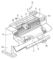
図1は本発明の一実施形態を適用した記録装置1の概略図である。記録装置1はシリアル型のインクジェット記録装置である。
<Outline of recording device>
FIG. 1 is a schematic diagram of a
なお、「記録」には、文字、図形等有意の情報を形成する場合のみならず、有意無意を問わず、広く記録媒体上に画像、模様、パターン等を形成する、又は媒体の加工を行う場合も含まれ、人間が視覚で知覚し得るように顕在化したものであるか否かを問わない。また、本実施形態では「記録媒体」としてシート状の紙を想定するが、布、プラスチック・フィルム等であってもよい。 In “recording”, not only when significant information such as characters and figures is formed, but also regardless of significance, images, patterns, patterns, etc. are widely formed on the recording medium, or the medium is processed. It does not matter whether or not it is manifested so that humans can perceive it visually. In this embodiment, a sheet-like paper is assumed as the “recording medium”, but a cloth, a plastic film, or the like may be used.
記録装置1は、互いに向き合った2つの脚部1aの上端部に跨るように固定されている。キャリッジ2には、記録ヘッド3が搭載されている。記録ヘッド3は記録媒体にインクを吐出して画像を記録する。
The
画像の記録時には、ロールホルダーユニット4にセットされた記録媒体(ここではロール紙)が記録位置まで副走査方向に給送される。そして、キャリッジ2がキャリッジモータ(不図示)及びベルト伝動機構5によって主走査方向に移動し、この移動の際に記録ヘッド3の各ノズルからインク滴が吐出される。
At the time of image recording, a recording medium (roll paper in this case) set in the roll holder unit 4 is fed in the sub-scanning direction to the recording position. The carriage 2 is moved in the main scanning direction by a carriage motor (not shown) and a
キャリッジ2が記録媒体の主走査方向の一方端まで移動すると、搬送ローラ6が所定量だけ記録媒体を副走査方向へ搬送する。このように記録動作と搬送動作とを交互に繰り返すことにより記録媒体全体に画像を形成する。画像形成後は、不図示のカッターによって記録媒体をカットし、カットされた記録媒体はスタッカ7に積載される。
When the carriage 2 moves to one end in the main scanning direction of the recording medium, the transport roller 6 transports the recording medium in the sub scanning direction by a predetermined amount. In this way, an image is formed on the entire recording medium by alternately repeating the recording operation and the conveying operation. After the image formation, the recording medium is cut by a cutter (not shown), and the cut recording medium is stacked on the
記録装置1は本発明の一実施形態に係る供給装置8を備えている。供給装置8には、複数の液体収容器9が収容されている。液体収容器9は本実施形態の場合、インクタンクであり、黒、シアン、マゼンタ、イエローなどといったインクの種類ごとに区画して上下方向に着脱自在に収容されている。供給装置8には、液体収容器9毎の供給用チューブ10が接続されている。供給用チューブ10はキャリッジ2の往復運動の際に暴れることのないように、チューブガイド10aによって束ねられている。
The
記録ヘッド3の記録媒体に対向した面には主走査方向と略直交した方向に複数のノズル列(図示省略)が形成されており、ノズル列単位で供給チューブ10が接続されている。供給装置8から供給チューブ10を介して液体収容器9内のインクがノズル列に供給される。
A plurality of nozzle rows (not shown) are formed on the surface of the
さらに回復ユニット11が主走査方向において記録媒体範囲外で、かつ記録ヘッド3のノズル面に対向する位置に設けられている。回復ユニット11は、必要に応じて記録ヘッド3の吐出ノズル表面からインク又は空気を吸い出すノズルのクリーニングや記録ヘッド3内部に溜まった空気を強制的に吸い出す弁閉じ吸引を行っている。記録装置1の右側には操作パネル12が設けられている。操作パネル12は液体収容器9内のインクが空になった際にワーニングメッセージを出してユーザーにアナウンスを出し、液体収容器9の交換を促すことができる。
Further, the
<供給装置の構造>
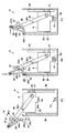
供給装置8の構造について説明する。図2(A)及び図2(B)は供給装置8の模式的な垂直断面図を示している。既に述べたように供給装置8には、複数の液体収容器9が収容インクの種類ごとに区画して収容されており、図2(A)及び図2(B)はその一区画分の構造を示している。
<Structure of supply device>
The structure of the
供給装置8は、操作ハンドル20と、ホルダ30と、リンク40と、収容部50とを備える。収容部50は、上方が開放した筒体をなしており、液体収容器9がその上方の開口部から出し入れされる。収容部50は、ホルダ30及びホルダ30に搭載される液体収容器9の少なくとも一部が収容される。
The
収容部50は、底部50a、対向する側部50b、および、対向する側部50cを備え、これらはいずれも収容部50の内部空間を画定する壁部を構成している。なお、図2(A)及び図2(B)では、片側の側部50cのみが図示されている。
The
底部50aには供給部13が設けられている。供給部13は液体収容器9と接続されて、液体収容器内のインクを液体収容器外へ供給する。本実施形態の場合、供給部13は底部50aから上方へ突出した供給針であり、液体収容器9に挿抜されることで、液体収容器9と接続及び接続解除される。二本の供給針の一方は大気連通用であり、他方はインク供給用である。大気連通用の供給針は不図示の大気連通口を通じて外気と通じており、液体収容器9の内部のインクが排出された分だけ液体収容器9の内部へ空気を導く。
The
液体収容器9内のインクは供給部13を介して供給用チューブ10に排出され、記録ヘッド3へ供給される。供給部13を底部50aに設け、また、後述するように液体収容器9の供給部13との接続部位を下部に設けることで液体収容器9のインクを最後まで使い切り易くすることができる。
The ink in the
対向する側部50bの一方には案内部55が、他方には案内部56がそれぞれ形成されている。案内部55は、ホルダ30の移動を案内する溝である。ホルダ30は案内部55に案内されて、収容部内において底部50aに対して近接及び離間する方向(ここでは上下方向)に移動可能である。案内部55は、リンク40の移動を案内する溝である。リンク40は案内部55に案内されてL字状に移動可能である。
A
対向する側部50bの一方には、係合部51、当接部53が形成されている。これらの機能については後述する。
An engaging
収容部50は、インクの容量が異なる複数種類の液体収容器9を収容するものであってもよい。液体収容器9の容量差がかなり大きい場合、例えば、大容量800ml、小容量300mlとし、断面積を同じとすると、約150mmの高さ差が生じる。本実施形態のように、供給部13を底部50aに設けた構成においては、小容量の液体収容器9を収容部50に脱着する際のリフト量(上下の移動量)は大きくなり、上述したように150mm以上のリフト量が必要となる。本実施形態の場合、リンク40を設けて操作ハンドル20とホルダ30とを連結しているので、より大きなリフト量を稼ぐことができる。
The
ホルダ30は、上方が開放した有底の箱型をなしており、その内側に液体収容器9が搭載される。ホルダ30には、不図示のロック機構が設けられ、このロック機構によって液体収容器9がホルダ30にロックされる。ホルダ30の底部には、供給部13と接続される液体収容器9の接続部位が通過する開口部30aが形成されている。ホルダ30の側部には回動軸32が設けられており、リンク40の一端部41が回動軸32に回動自在に連結されている。
The
ホルダ30の側部には、案内部55と係合するスライダ31が設けられている。スライダ31は本実施形態の場合軸体であり、案内部55をスライド自在となっており、ホルダ30と液体収容器9は案内部55の案内によって上下に移動する。図2(A)は、ホルダ30が、液体収容器9と供給部13とが接続される位置(接続位置と呼ぶ)に位置している場合を示している。図2(B)はホルダ30が、液体収容器9と供給部13とが離間し、液体収容器9が交換される位置(交換位置と呼ぶ)に位置している場合を示している。
A
リンク40は、棒状の部材であり、その一端部41が回動軸32により回動自在にホルダ30に連結されている。その他端部42には回動軸21により操作ハンドル20が回動自在に連結されている。リンク40の長さは、ホルダ30が接続位置に位置している場合に、操作ハンドル20を収容部50から露出させるように設定されている。
The
リンク40の途中部位には、案内部56と係合するスライダ40cが設けられている。スライダ40cは本実施形態の場合軸体であり、案内部56をスライド自在となっている。案内部56はリンク40の移動を案内すると共にその自由移動を規制している。リンク40の他端部42側には、規制部40a、40bが設けられている。規制部40a、40bは本実施形態の場合軸体であり、後述するようにリンク40に対する操作ハンドル20の回動を規制可能である。
A
操作ハンドル20は、リンク40に対する回動によってホルダ30に搭載された液体収容器9の、供給部13に対する接続及び接続解除を操作するためのハンドルである。操作ハンドル20の中央部には回動軸21が設けられており、ここにリンク40が連結されている。ハンドル20の一端部には、係合部51と係合する係合部20cが形成されている。また、ハンドル20の他端部には、ユーザが把持することを想定した把持部20aが形成されている。
The operation handle 20 is a handle for operating connection and disconnection of the
係合部20cは係合部51と係合可能である。図2(A)は係合状態を示している。この係合と、リンク40に対する操作ハンドル20の回動規制によって、ホルダ30に搭載された液体収容器9と供給部13との接続状態が維持される。
The engaging
供給装置8は、また、二つの回動規制ユニット14及び15を備える。これらの回動規制ユニット14及び15は、いずれも、リンク40に対する操作ハンドル20の回動を規制可能な機構である。
The
回動規制ユニット14は、ユーザの操作によってリンク40に対する操作ハンドル20の回動規制及び規制解除可能なユニットである。回動規制ユニット14は、操作ハンドル20に設けた規制部材27と、リンク40に設けた規制部40bとを備える。規制部材27は、レバー状の部材であり、回動軸27cを介して操作ハンドル20に回動自在に支持されている。規制部材27の一端部には、フック形状のフック部27aが設けられており、他端部にはユーザが把持することを想定した把持部27bが設けられている。図2(A)に示すようにフック部27aが規制部40bと係合することで操作ハンドル20はリンク40に対して回動不能となる。図2(B)に示すようにフック部27aと規制部40bとの係合を解除することで操作ハンドル20はリンク40に対して回動可能となる。
The
把持部20aと把持部27bとの間には、バネ等の弾性部材28が設けられている。弾性部材28は、フック部27aが規制部40bと係合する方向に規制部材27を常時付勢する。図2(A)で矢印Eで示すようにユーザが弾性部材28の付勢に抗して把持部20aへ把持部27bを近接するようにこれらを把持することで、フック部27aが規制部40bと係合しない方向に規制部材27を回動させる。
An
回動規制ユニット14によって操作ハンドル20をリンク40に対して回動不能とする操作(把持部20a及び把持部27bの把持解放)は、液体収容器9の装着完了時、つまり、ホルダ30を図2(A)の接続位置に維持する場合に行われる。これにより係合部51と係合部20cとの係合が維持され、液体収容器9と供給部13との接続状態が維持される。
An operation for making the operation handle 20 unrotatable with respect to the
回動規制ユニット14によって操作ハンドル20をリンク40に対して回動可能とする操作(把持部20a及び把持部27bの把持)は、装着されている液体収容器9の取り出し時に行われる。つまりホルダ30を図2(A)の接続位置から交換位置へ移動する場合に行われる。操作ハンドル20の回動によって係合部51と係合部20cとの係合が解除されて非係合状態となり、液体収容器9と供給部13との接続も解除される。このとき、ユーザは把持部20a及び把持部27bを把持したまま、操作ハンドル20を持ち替えることなく、リフト動作に移ることができ、操作性が向上する。また、操作に伴うユーザの手首の折れ曲がりが解消され操作性が改善される。
The operation of allowing the operation handle 20 to rotate with respect to the
しかしながら、リフト動作中に操作ハンドル20がリンク40に対して回動可能であるとすると、今度は、リフト動作中、操作ハンドル20がふらふらして安定性に欠ける場合がある。回動規制ユニット15はその対策の機構である。回動規制ユニット15は、係合部51と操作ハンドル20の係合部20cとが非係合状態にある場合に、リンク40に対する操作ハンドル20の回動を規制可能である。これにより、操作ハンドル20の安定性を向上することができる。
However, if the operation handle 20 is rotatable with respect to the
回動規制ユニット15は、操作ハンドル20に設けた規制部材25と、リンク40に設けた規制部40aとを備える。規制部材25は、レバー状の部材であり、回動軸25bを介して操作ハンドル20に回動自在に支持されている。規制部材25の一端部には、フック形状のフック部25aが設けられており、他端部には操作ハンドル20の当接部20cに隣接した解除部25cが設けられている。図2(B)に示すようにフック部25aが規制部40aと係合することで操作ハンドル20はリンク40に対して回動不能となる。図2(A)に示すように当接部53が解除部25cに当接すると、フック部25aと規制部40aとの係合が解除され操作ハンドル20はリンク40に対して回動可能となる。
The
回動規制ユニット15は、規制部材25を規制部40aと係合する方向へ常時付勢する弾性部材15aを備える。弾性部材15aは本実施形態の場合、回動軸25bに巻かれたコイルばねであり、その一端は操作ハンドル20に係止され、他端は規制部材25に係止されている。弾性部材15aの付勢によって、解除部25cが当接部53から押圧を受けない限り、フック部25aが規制部40aと係合する。したがって、リフト動作中に、操作ハンドル20がリンク40に対して回動することを防止できる。
The
<液体収容器の着脱動作>
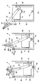
液体収容器9の着脱に関する供給装置8の動作を説明する。まず、図3(A)〜図4(B)を参照して液体収容器9の装着方法について説明する。
<Mounting / removing operation of liquid container>
The operation of the
図3(A)に示すように、ユーザの手動操作によりホルダ30が交換位置に配置され、ホルダ30に液体収容器9が搭載される。液体収容器9は、その底部に供給部13と脱着される接続部9aを有している。液体収容器9は、接続部9aが開口部30aを通過した状態でホルダ30にロックされる。接続部9aは、例えば、供給部13が挿抜されるゴムを含む。ゴムには極細のスリットが切られており、供給部13はこのスリットに挿抜される。回動規制ユニット15はリンク40に対する操作ハンドル20の回動を規制した状態にある。
As shown in FIG. 3A, the
液体収容器9をホルダ30に搭載すると、図3(B)に示すようにユーザは操作ハンドル20を把持して、スライダ40cに対する案内部56の案内にしたがって、操作ハンドル20を移動する。把持部20aと把持部27bとを把持することで、回動規制ユニット14はリンク40に対する操作ハンドル20の回動の規制を解除した状態になるが、回動規制ユニット15は回動を規制した状態にある。したがって、操作ハンドル20がふらふらすることを防止し、安定性を向上できる。
When the
本実施形態では、操作ハンドル20と係合部51との係合開始に伴って、回動規制ユニット15がリンク40に対する操作ハンドル20の回動の規制を解除するように、係合部51、当接部53、係合部20c及び解除部25cが配置されている。これにより一連の操作を円滑に行える。具体的には以下の通りである。
In the present embodiment, with the start of engagement between the operation handle 20 and the
操作ハンドル20は少し持ち上げられ、その後、矢印D方向に押し下げられる。これにより、規制部材25の解除部25cが当接部53と当接する。規制部材25は矢印G方向に回動し、フック部25aと規制部40aとの係合が解除される。これによりリンク40に対する操作ハンドル20の回動の規制が解除され、回動自在な状態になる。図3(C)に示すように、ユーザは矢印K方向に操作ハンドル20を押圧する。すると、操作ハンドル20はリンク40に対して矢印K方向に回動し、操作ハンドル20の係合部20cが係合部51と係合する。係合部51との係合によって、操作ハンドル20は上方向へ移動できない。係合部20cと係合部51とが支点として機能するてこの原理により液体収容器9は供給部13に対して押し下げられていく。
The operation handle 20 is slightly lifted and then pushed down in the direction of arrow D. As a result, the
図4(A)に示すように、接続部9aが供給部13と接触し、供給部13が接続部9aに挿入される。接続部9aと供給部13との接続が完了する位置に至ると、図4(B)に示すようにユーザは、把持部27bを解放する。これにより弾性部材28の付勢で規制部40bが回動し、回動規制ユニット14によってリンク40に対する操作ハンドル20の回動が規制される。その後、ユーザは操作ハンドル20から手を離すことができる。一連の操作中、手の位置、手首の角度等の操作姿勢をほとんど変えず行うことができ、操作性を悪化させることはない。
As shown in FIG. 4A, the
液体収容器9には接続部9aの反力により、上方向に押し上げる力を受ける。しかし、規制ユニット14によってリンク40に対する操作ハンドル20の回動(特に図4(B)の矢印H方向)が規制されており、かつ、係合部51と係合部20cとの係合によって操作ハンドル20が上方向に変位することが規制されている。したがって、液体収容器9の浮き上がりを抑制し、接続部9aと供給部13との接続を維持できる。その後、供給部13からはインクが排出される。
The
次に、図5(A)〜図5(C)を参照して液体収容器9の取り外し方法について説明する。取り外し方法は基本的に装着方法の逆の手順となる。ユーザが把持部20aと把持部27bとを把持することで、回動規制ユニット14がリンク40に対する操作ハンドル20の回動の規制を解除した状態になる。
Next, a method for removing the
続いて図5(A)で矢印Hで示すように操作ハンドル20をリンク40に対して回動させながら図5(B)において矢印J方向に操作ハンドル20を引き上げる。これにより、液体収容器9がリフトし始め、接続部9aと供給部13との接続が解除される。また、規制部材25の解除部25cが当接部53から離間する。これにより、弾性部材15aの付勢で規制部材25が回動してフック部25aと規制部40aとが係合する。そして、リンク40に対する操作ハンドル20の回動が規制される。
Subsequently, as shown by an arrow H in FIG. 5A, the operation handle 20 is pulled up in the direction of arrow J in FIG. Thereby, the
ユーザは操作ハンドル20を更に引き上げることで、図5(C)に示すようにホルダ30が交換位置に到達する。ユーザはこのリフト操作への切り換えにおいて、指を持ち換えることなく操作ができる。このリフト操作の間、リンク40に対する操作ハンドル20の回動が回動規制ユニット15で規制されるので、操作ハンドル20がふらふらすることなく、安定性を向上できる。
When the user further pulls up the
<第二実施形態>
液体収容器9の接続部9aへの供給部13の挿抜の抵抗が高いと、挿抜操作力が大きくなる。この挿抜の際には、てこの原理を利用して挿抜操作力を低減することが有効である。このてこ比は、約2〜3倍であると有利である。しかし、上述したように、大小の液体収容器9を併用可能とし、小の液体収容器9のリフト量が150mmとなると、リフト操作を含めててこの原理を利用した構成とすると、リンク40等の全長が大型化する傾向にある。
<Second embodiment>
If the resistance of insertion / extraction of the
このため、第一実施形態では、接続部9aと供給部13との接続に際して、てこの原理が作用する構成とし、リフト操作においてはてこの原理を利用しない構成とした。本実施形態ではリフト操作においてはてこの原理を利用しない構成としつつ、接続部9aと供給部13との接続解除においてもてこの原理が作用する構成としたものである。
For this reason, in the first embodiment, when the
図6(A)〜図7(C)は、本実施形態における液体収容器9の着脱動作の説明図である。図6(A)を参照して、本実施形態では、第一実施形態の係合部51、係合部20cに代わる係合部51’、係合部20c’が採用されている。他の構造は第一実施形態と同様である。
FIG. 6A to FIG. 7C are explanatory diagrams of the attaching / detaching operation of the
係合部51’は、係合部20c’が下からだけでなく上からも当接できるように、側部50bから突出して形成されており、本実施形態の場合、球状に形成されている。係合部20c’は、係合部51’に下から当接する部分と上から当接する部分とを有している。本実施形態の場合、係合部20c’は二股に分岐したくちばし形状を有している。
The engaging
なお、図6(A)〜図7(C)においては、説明を簡略化するために、回動規制ユニット15及び当接部53の図示を省略し、図8(A)及び図8(B)に図示している。これらの構成は第一実施形態と同様である。図8(A)に示すように規制部材25の解除部25cが当接部53と当接すると、フック部25aと規制部40aとの係合が解除される。また、図8(B)に示すように規制部材25の解除部25cが当接部53から離間すると、弾性部材15aの付勢でフック部25aと規制部40aとが係合する。
In FIGS. 6A to 7C, the
図6(A)〜図7(A)を参照して液体収容器9の装着方法について説明する。図6(A)に示すように、ユーザの手動操作によりホルダ30が交換位置に配置され、ホルダ30に液体収容器9が搭載される。図示していないが回動規制ユニット15はリンク40に対する操作ハンドル20の回動を規制した状態にある。
A mounting method of the
ユーザは操作ハンドル20を把持して、スライダ40cに対する案内部56の案内にしたがって、操作ハンドル20を移動する。把持部20aと把持部27bとを把持することで、回動規制ユニット14はリンク40に対する操作ハンドル20の回動の規制を解除した状態になるが、回動規制ユニット15は回動を規制した状態にある。したがって、操作ハンドル20がふらふらすることを防止し、安定性を向上できる。
The user grasps the operation handle 20 and moves the operation handle 20 in accordance with the guidance of the
操作ハンドル20は少し持ち上げられ、その後、図6(B)に示すように矢印D方向に押し下げられる。図示していないが、これにより、規制部材25の解除部25cが当接部53と当接し、リンク40に対する操作ハンドル20の回動の規制が解除され、回動自在な状態になる。
The operation handle 20 is slightly lifted and then pushed down in the direction of arrow D as shown in FIG. Although not shown, by this, the
ユーザが操作ハンドル20の把持部20a側を下方へ押圧する。すると、操作ハンドル20が回動しつつ係合部20c’が係合部51’に下から当接する。係合部20c’と係合部51’とを支点とした、てこの原理により液体収容器9は供給部13に対して押し下げられていく。すると接続部9aと供給部13との接続が開始される。
The user presses the
この時、係合部20c’と係合部51’との支点と操作ハンドル20の回転中心距離L3と、支点と把持部20aとの距離L4とのてこ比L4/L3が、回動軸21に作用するので、操作力はこのてこ比だけ倍力化される。
At this time, the lever ratio L4 / L3 between the fulcrum between the engaging
さらに、操作ハンドル20を押しこむと、液体収容器9が降下して接続部9aと供給部13との接続が完了する。ユーザは、把持部27bを解放する。これにより弾性部材28の付勢で規制部40bが回動し、回動規制ユニット14によってリンク40に対する操作ハンドル20の回動が規制される。その後、ユーザは操作ハンドル20から手を離すことができる。一連の操作中、手の位置、手首の角度等の操作姿勢をほとんど変えず行うことができ、操作性を悪化させることはない。
Further, when the operation handle 20 is pushed in, the
液体収容器9には接続部9aの反力により、上方向に押し上げる力を受ける。しかし、規制ユニット14によってリンク40に対する操作ハンドル20の回動が規制されており、かつ、係合部51’と係合部20c’との係合によって操作ハンドル20が上方向に変位することが規制されている。したがって、液体収容器9の浮き上がりを抑制し、接続部9aと供給部13との接続を維持できる。その後、図7(A)に示すように供給部13からはインクが排出される。
The
次に、図7(A)〜図7(C)を参照して液体収容器9の取り外し方法について説明する。ユーザが把持部20aと把持部27bとを把持することで、回動規制ユニット14がリンク40に対する操作ハンドル20の回動の規制を解除した状態になる。
Next, a method for removing the
続いて図7(A)で矢印Aで示すように操作ハンドル20をリンク40に対して回動させると図7(B)に示すように係合部20c’が係合部51’に上から当接する。係合部20c’と係合部51’とを支点とした、てこの原理により液体収容器9は供給部13に対して押し上げられていく。すると接続部9aと供給部13との接続の解除が開始される。
Subsequently, when the operation handle 20 is rotated with respect to the
この時、図7(C)に示すように、係合部20c’と係合部51’との支点と、操作ハンドル20の回転中心距離L1と、支点と把持部20aとの距離L2とのてこ比L2/L1が、回動軸21に作用するので、操作力はこのてこ比だけ倍力化される。
At this time, as shown in FIG. 7C, the fulcrum between the engaging
接続部9aと供給部13との接続が解除されると、ユーザは操作ハンドル20を引き上げる。これにより、液体収容器9がリフトされ、また、不図示の規制部材25の解除部25cが当接部53から離間する。これにより、回動規制ユニット15によってリンク40に対する操作ハンドル20の回動が規制される。
When the connection between the
ユーザは操作ハンドル20を更に引き上げることで、図6(A)に示すようにホルダ30が交換位置に到達する。ユーザはこのリフト操作への切り換えにおいて、指を持ち換えることなく操作ができる。このリフト操作の間、リンク40に対する操作ハンドル20の回動が回動規制ユニット15で規制されるので、操作ハンドル20がふらふらすることなく、安定性を向上できる。
When the user further pulls up the
<第三実施形態>
第一実施形態や第二実施形態における接続部9aと供給部13との接続または接続解除においては、回動軸21の変位が規制されることで、てこの原理がより有効に作用する。そこで、回動軸21の所定方向の変位を規制する変位規制ユニットを設けてもよい。
<Third embodiment>
In the connection or disconnection of the
図9はその一例を示す。同図の例は、第二実施形態の構成において、変位規制ユニット16を設けているが第一実施形態の構成にも適用可能である。本実施形態における変位規制ユニット16は、回動軸21の周囲のボス部を挟む一対の壁部を構成しており、例えば、収容部50の対向する側部50cの一方に固定される。
FIG. 9 shows an example. The example of the figure is provided with the
変位規制ユニット16は、接続部9aと供給部13とが接続または解除されるときに、回動軸21の周囲のボス部を挟む位置に配設され、そのN方向の変位を規制する。N方向は、接続部9aと供給部13との接続及び解除の方向と交差する方向(例えば直交する方向)である。本実施形態の場合、接続部9aと供給部13との接続及び解除の方向は上下方向であるので、N方向は左右方向である。
The
このような変位規制ユニット16を設けることで、てこの原理をより効果的に作用させることができる。
By providing such a
<他の実施形態>
第一実施形態から第三実施形態では、液体収容器9が、インクを収容するインクタンクである例を例示したが、本発明はインク以外の液体を収容する液体収容器についても適用可能である。
<Other embodiments>
In the first to third embodiments, the
8 供給装置、9 液体収容器、13 供給部、30 ホルダ、40 リンク、20 操作ハンドル、51 係合部、15 回動規制ユニット 8 Supply Device, 9 Liquid Container, 13 Supply Unit, 30 Holder, 40 Link, 20 Operation Handle, 51 Engagement Unit, 15 Rotation Restriction Unit
Claims (12)
液体収容器が搭載されるホルダと、
前記ホルダに連結されたリンクと、
前記リンクに回動自在に連結され、前記リンクに対する回動によって前記ホルダに搭載された液体収容器の、前記供給部に対する接続及び接続解除を操作する操作ハンドルと、
前記操作ハンドルと係合して前記ホルダに搭載された液体収容器と前記供給部との接続状態を維持する係合部と、
前記係合部と前記操作ハンドルとが非係合状態にある場合に、前記リンクに対する前記操作ハンドルの回動を規制可能な回動規制手段と、を備える、
ことを特徴とする供給装置。 A supply unit for supplying the liquid in the liquid container to the outside of the liquid container;
A holder on which a liquid container is mounted;
A link connected to the holder;
An operation handle that is connected to the link so as to be rotatable, and operates to connect and disconnect the liquid container mounted on the holder by rotation with respect to the link.
An engagement portion that engages with the operation handle and maintains a connection state between the liquid container mounted on the holder and the supply portion;
Rotation regulation means capable of regulating rotation of the operation handle with respect to the link when the engagement portion and the operation handle are in a non-engaged state;
A supply device characterized by that.
前記回動規制手段は、前記操作ハンドルと前記係合部との係合開始に伴って、前記リンクに対する前記操作ハンドルの回動の規制を解除する、
ことを特徴とする供給装置。 The supply device according to claim 1,
The rotation restricting means releases the restriction of the rotation of the operation handle with respect to the link as the operation handle and the engagement portion start to be engaged.
A supply device characterized by that.
前記回動規制手段は、
前記操作ハンドルに回動自在に支持された規制部材と、
前記リンクに設けられ、前記規制部材との係合によって前記リンクに対する前記操作ハンドルの回動を規制する規制部と、を備え、
前記操作ハンドルと前記係合部との係合開始に伴って前記規制部材と当接し、該規制部材を、前記規制部との係合が解除される方向に回動させる当接部を更に備える、
ことを特徴とする供給装置。 The supply device according to claim 1,
The rotation restricting means is
A regulating member rotatably supported by the operation handle;
A restricting portion that is provided on the link and restricts rotation of the operation handle with respect to the link by engagement with the restricting member;
An abutting portion that abuts on the restriction member when the operation handle and the engagement portion start to be engaged and rotates the restriction member in a direction in which the engagement with the restriction portion is released is further provided. ,
A supply device characterized by that.
前記回動規制手段は、前記規制部材を前記規制部と係合する方向へ付勢する弾性部材を更に備える、
ことを特徴とする供給装置。 The supply device according to claim 3,
The rotation restricting means further includes an elastic member that urges the restricting member in a direction to engage with the restricting portion.
A supply device characterized by that.
前記ホルダに搭載された液体収容器と前記供給部との接続解除の際、前記操作ハンドルと係合して、てこの原理の支点として機能する第二の係合部を更に備える、
ことを特徴とする供給装置。 The supply device according to claim 1,
When the connection between the liquid container mounted on the holder and the supply unit is released, the liquid handle further includes a second engagement portion that engages with the operation handle and functions as a fulcrum of the lever principle.
A supply device characterized by that.
前記係合部は、前記ホルダに搭載された液体収容器と前記供給部との接続の際、前記操作ハンドルと係合して、てこの原理の支点として機能し、
前記ホルダに搭載された液体収容器と前記供給部との接続の際、前記操作ハンドルと前記リンクとの回動軸の所定方向の変位を規制する変位規制手段を更に備える、
ことを特徴とする供給装置。 The supply device according to claim 1,
The engaging portion engages with the operation handle at the time of connection between the liquid container mounted on the holder and the supply portion, and functions as a fulcrum of the lever principle,
A displacement restricting means for restricting a displacement of a rotation axis between the operation handle and the link in a predetermined direction when the liquid container mounted on the holder is connected to the supply unit;
A supply device characterized by that.
前記リンクに対する前記操作ハンドルの回動を解除可能に規制する第二の回動規制手段を更に備え、
前記第二の回動規制手段は、ユーザの操作によって規制解除が可能である、
ことを特徴とする供給装置。 The supply device according to claim 1,
A second rotation restricting means for releasably restricting the rotation of the operation handle with respect to the link;
The second rotation restricting means can be deregulated by a user operation.
A supply device characterized by that.
前記ホルダ及び前記ホルダに搭載される液体収容器の少なくとも一部を収容する収容部を更に備え、
前記供給部は、前記収容部の底部に設けられ、
前記ホルダは、前記収容部内において前記底部に対して近接及び離間する方向に移動可能に設けられ、
前記回動規制手段は、前記ホルダを前記収容部内において前記方向に移動する場合に、前記リンクに対する前記操作ハンドルの回動を規制する、
ことを特徴とする供給装置。 The supply device according to claim 1,
A storage section for storing at least a part of the holder and a liquid container mounted on the holder;
The supply unit is provided at the bottom of the storage unit,
The holder is provided so as to be movable in a direction approaching and separating from the bottom portion in the housing portion,
The rotation restricting means restricts the rotation of the operation handle with respect to the link when the holder is moved in the direction in the accommodating portion.
A supply device characterized by that.
前記ホルダ及び前記ホルダに搭載される液体収容器の少なくとも一部を収容する収容部を更に備え、
前記供給部は、前記収容部の底部に設けられ、
前記ホルダは、前記収容部内において前記底部に対して近接及び離間する方向に移動可能に設けられ、
前記係合部及び前記当接部は、前記収容部の壁部に設けられている、
ことを特徴とする供給装置。 The supply device according to claim 3,
A storage section for storing at least a part of the holder and a liquid container mounted on the holder ;
The supply unit is provided at the bottom of the storage unit,
The holder is provided so as to be movable in a direction approaching and separating from the bottom portion in the housing portion,
The engaging portion and the contact portion are provided on a wall portion of the housing portion,
A supply device characterized by that.
前記液体収容器が、インクを収容するインクタンクである、
ことを特徴とする供給装置。 The supply device according to claim 1,
The liquid container is an ink tank for containing ink;
A supply device characterized by that.
前記供給装置から供給される液体を吐出して画像を記録する記録手段と、
を備えた記録装置であって、
前記供給装置は、
液体収容器内の液体を液体収容器外へ供給する供給部と、
液体収容器が搭載されるホルダと、
前記ホルダに連結されたリンクと、
前記リンクに回動自在に連結され、前記リンクに対する回動によって前記ホルダに搭載された液体収容器の、前記供給部に対する接続及び接続解除を操作する操作ハンドルと、
前記操作ハンドルと係合して前記ホルダに搭載された液体収容器と前記供給部との接続状態を維持する係合部と、
前記係合部と前記操作ハンドルとが非係合状態にある場合に、前記リンクに対する前記操作ハンドルの回動を規制可能な回動規制手段と、を備える、
ことを特徴とする記録装置。 A feeding device;
Recording means for recording an image by discharging liquid supplied from the supply device;
A recording device comprising:
The supply device includes:
A supply unit for supplying the liquid in the liquid container to the outside of the liquid container;
A holder on which a liquid container is mounted;
A link connected to the holder;
An operation handle that is connected to the link so as to be rotatable, and operates to connect and disconnect the liquid container mounted on the holder by rotation with respect to the link.
An engagement portion that engages with the operation handle and maintains a connection state between the liquid container mounted on the holder and the supply portion;
Rotation regulation means capable of regulating rotation of the operation handle with respect to the link when the engagement portion and the operation handle are in a non-engaged state;
A recording apparatus.
前記供給装置は、
液体収容器内の液体を液体収容器外へ供給する供給部と、
液体収容器が搭載されるホルダと、
前記ホルダに連結されたリンクと、
前記リンクに回動自在に連結され、前記リンクに対する回動によって前記ホルダに搭載された液体収容器の、前記供給部に対する接続及び接続解除を操作する操作ハンドルと、
前記リンクに対する前記操作ハンドルの回動を解除可能に規制する回動規制手段と、を備え、
前記装着方法は、
液体収容器を前記ホルダに搭載する工程と、
前記操作ハンドルの移動によって、前記ホルダに搭載された液体収容器を前記供給部へ移動する移動工程と、
前記操作ハンドルの回動によって、前記ホルダに搭載された液体収容器と前記供給部とを接続する接続工程と、を備え、
前記移動工程では前記回動規制手段によって前記リンクに対する前記操作ハンドルの回動を規制し、前記接続工程では前記回動規制手段による規制を解除する、
ことを特徴とする装着方法。 A method for mounting a liquid container on a supply device, comprising:
The supply device includes:
A supply unit for supplying the liquid in the liquid container to the outside of the liquid container;
A holder on which a liquid container is mounted;
A link connected to the holder;
An operation handle that is connected to the link so as to be rotatable, and operates to connect and disconnect the liquid container mounted on the holder by rotation with respect to the link.
A rotation restricting means for releasably restricting the rotation of the operation handle with respect to the link;
The mounting method is:
Mounting a liquid container on the holder;
A movement step of moving the liquid container mounted on the holder to the supply unit by moving the operation handle;
A connection step of connecting the liquid container mounted on the holder and the supply unit by turning the operation handle; and
In the moving step, the rotation restricting means restricts the rotation of the operation handle relative to the link, and in the connecting step, the restriction by the rotation restricting means is released.
A mounting method characterized by that.
Priority Applications (2)
| Application Number | Priority Date | Filing Date | Title |
|---|---|---|---|
| JP2015194401A JP6422420B2 (en) | 2015-09-30 | 2015-09-30 | Supply device, recording device, and mounting method |
| US15/266,699 US9902160B2 (en) | 2015-09-30 | 2016-09-15 | Supply apparatus, printing apparatus, and attachment method |
Applications Claiming Priority (1)
| Application Number | Priority Date | Filing Date | Title |
|---|---|---|---|
| JP2015194401A JP6422420B2 (en) | 2015-09-30 | 2015-09-30 | Supply device, recording device, and mounting method |
Publications (3)
| Publication Number | Publication Date |
|---|---|
| JP2017065129A JP2017065129A (en) | 2017-04-06 |
| JP2017065129A5 JP2017065129A5 (en) | 2018-02-08 |
| JP6422420B2 true JP6422420B2 (en) | 2018-11-14 |
Family
ID=58408941
Family Applications (1)
| Application Number | Title | Priority Date | Filing Date |
|---|---|---|---|
| JP2015194401A Active JP6422420B2 (en) | 2015-09-30 | 2015-09-30 | Supply device, recording device, and mounting method |
Country Status (2)
| Country | Link |
|---|---|
| US (1) | US9902160B2 (en) |
| JP (1) | JP6422420B2 (en) |
Families Citing this family (3)
| Publication number | Priority date | Publication date | Assignee | Title |
|---|---|---|---|---|
| US11077670B2 (en) | 2018-01-30 | 2021-08-03 | Canon Kabushiki Kaisha | Inkjet printing apparatus and ink filling method |
| JP7292947B2 (en) | 2019-04-24 | 2023-06-19 | キヤノン株式会社 | INKJET RECORDING DEVICE AND CONTROL METHOD OF INKJET RECORDING DEVICE |
| JP7447535B2 (en) * | 2020-02-20 | 2024-03-12 | ブラザー工業株式会社 | image recording device |
Family Cites Families (10)
| Publication number | Priority date | Publication date | Assignee | Title |
|---|---|---|---|---|
| JP3627790B2 (en) * | 1997-09-25 | 2005-03-09 | セイコーエプソン株式会社 | Ink cartridge attaching / detaching device in recording apparatus |
| JPH11188890A (en) | 1997-10-20 | 1999-07-13 | Canon Inc | Ink replenishing method and liquid jet recorder employing it |
| JP3009040B1 (en) * | 1998-11-26 | 2000-02-14 | セイコーエプソン株式会社 | Ink jet recording device |
| US6412911B1 (en) * | 2000-06-19 | 2002-07-02 | Xerox Corporation | Ink tank support assembly seal and biasing element |
| JP3081030U (en) * | 2001-04-12 | 2001-10-19 | 船井電機株式会社 | Ink jet recording device |
| JP4769522B2 (en) | 2005-09-09 | 2011-09-07 | キヤノン株式会社 | Recording head recovery device and inkjet recording device |
| JP5483910B2 (en) | 2009-03-10 | 2014-05-07 | キヤノン株式会社 | Inkjet recording device |
| JP2011051318A (en) * | 2009-09-04 | 2011-03-17 | Ricoh Co Ltd | Liquid container housing device and image forming apparatus |
| JP5979917B2 (en) | 2012-03-09 | 2016-08-31 | キヤノン株式会社 | Inkjet recording device |
| JP6066756B2 (en) | 2012-03-09 | 2017-01-25 | キヤノン株式会社 | Recording device |
-
2015
- 2015-09-30 JP JP2015194401A patent/JP6422420B2/en active Active
-
2016
- 2016-09-15 US US15/266,699 patent/US9902160B2/en active Active
Also Published As
| Publication number | Publication date |
|---|---|
| JP2017065129A (en) | 2017-04-06 |
| US20170087854A1 (en) | 2017-03-30 |
| US9902160B2 (en) | 2018-02-27 |
Similar Documents
| Publication | Publication Date | Title |
|---|---|---|
| JP5066017B2 (en) | Image forming apparatus | |
| JP4167830B2 (en) | Latch and handle structure for replaceable ink containers | |
| JP6422420B2 (en) | Supply device, recording device, and mounting method | |
| EP1541357B1 (en) | Ink cartridge and ink jet printer | |
| US8678574B2 (en) | Printing apparatus | |
| JP2017209945A (en) | Liquid injection device | |
| KR100745919B1 (en) | Ink container for reliable electrical connection with a receiving station | |
| JP6160270B2 (en) | Maintenance unit and liquid ejecting apparatus | |
| JP2008132797A (en) | Ink cartridge and inkjet printer | |
| JP6494352B2 (en) | Liquid discharge head | |
| JP5057956B2 (en) | Printer solid ink transport and method | |
| JP7137785B2 (en) | Portable image forming apparatus and main body of portable image forming apparatus | |
| JP2007160795A (en) | Liquid jet attachment | |
| KR100470709B1 (en) | ink-cartridge for ink-jet printer | |
| JP2007111864A (en) | Recording liquid cartridge and image forming apparatus | |
| JP2017209947A (en) | Liquid injection device | |
| JP2006347021A (en) | Method of recovering ink of image recording device and ink recovery device | |
| JP4605398B2 (en) | Feed cassette device, recording device | |
| JP6102199B2 (en) | Image forming apparatus | |
| US20240025179A1 (en) | Liquid storage container and recording apparatus | |
| JP2008246991A (en) | Liquid container, attachment and liquid jet apparatus | |
| JP6229467B2 (en) | Recording device | |
| CN210733594U (en) | Cartridge-introducing apparatus, compartment of a CIJ-type ink jet printer and CIJ-type ink jet printer | |
| JPH11320904A (en) | Ink-jet recording apparatus and ink tank loaded to the apparatus | |
| JP4001000B2 (en) | Inkjet recording device |
Legal Events
| Date | Code | Title | Description |
|---|---|---|---|
| A521 | Written amendment |
Free format text: JAPANESE INTERMEDIATE CODE: A523 Effective date: 20171219 |
|
| A621 | Written request for application examination |
Free format text: JAPANESE INTERMEDIATE CODE: A621 Effective date: 20171219 |
|
| A977 | Report on retrieval |
Free format text: JAPANESE INTERMEDIATE CODE: A971007 Effective date: 20180905 |
|
| TRDD | Decision of grant or rejection written | ||
| A01 | Written decision to grant a patent or to grant a registration (utility model) |
Free format text: JAPANESE INTERMEDIATE CODE: A01 Effective date: 20180918 |
|
| A61 | First payment of annual fees (during grant procedure) |
Free format text: JAPANESE INTERMEDIATE CODE: A61 Effective date: 20181016 |
|
| R151 | Written notification of patent or utility model registration |
Ref document number: 6422420 Country of ref document: JP Free format text: JAPANESE INTERMEDIATE CODE: R151 |