JP6422295B2 - Image forming apparatus - Google Patents

Image forming apparatus Download PDF

Info

Publication number
JP6422295B2
JP6422295B2 JP2014207388A JP2014207388A JP6422295B2 JP 6422295 B2 JP6422295 B2 JP 6422295B2 JP 2014207388 A JP2014207388 A JP 2014207388A JP 2014207388 A JP2014207388 A JP 2014207388A JP 6422295 B2 JP6422295 B2 JP 6422295B2
Authority
JP
Japan
Prior art keywords
temperature
image forming
unit
forming apparatus
cooling
Prior art date
Legal status (The legal status is an assumption and is not a legal conclusion. Google has not performed a legal analysis and makes no representation as to the accuracy of the status listed.)
Active
Application number
JP2014207388A
Other languages
Japanese (ja)
Other versions
JP2016075850A (en
JP2016075850A5 (en
Inventor
寿文 角谷
寿文 角谷
崇元 飯倉
崇元 飯倉
修司 小幡
修司 小幡
菅田 光洋
光洋 菅田
三宅 和則
和則 三宅
洋介 畑
洋介 畑
鈴木 慎也
慎也 鈴木
裕寿 嘉藤
裕寿 嘉藤
学 小関
学 小関
健之 須田
健之 須田
敏行 阿部
敏行 阿部
佐藤 和美
和美 佐藤
Current Assignee (The listed assignees may be inaccurate. Google has not performed a legal analysis and makes no representation or warranty as to the accuracy of the list.)
Canon Inc
Original Assignee
Canon Inc
Priority date (The priority date is an assumption and is not a legal conclusion. Google has not performed a legal analysis and makes no representation as to the accuracy of the date listed.)
Filing date
Publication date
Application filed by Canon Inc filed Critical Canon Inc
Priority to JP2014207388A priority Critical patent/JP6422295B2/en
Priority to US14/873,767 priority patent/US9910407B2/en
Publication of JP2016075850A publication Critical patent/JP2016075850A/en
Publication of JP2016075850A5 publication Critical patent/JP2016075850A5/ja
Application granted granted Critical
Publication of JP6422295B2 publication Critical patent/JP6422295B2/en
Active legal-status Critical Current
Anticipated expiration legal-status Critical

Links

Images

Classifications

    • GPHYSICS
    • G03PHOTOGRAPHY; CINEMATOGRAPHY; ANALOGOUS TECHNIQUES USING WAVES OTHER THAN OPTICAL WAVES; ELECTROGRAPHY; HOLOGRAPHY
    • G03GELECTROGRAPHY; ELECTROPHOTOGRAPHY; MAGNETOGRAPHY
    • G03G21/00Arrangements not provided for by groups G03G13/00 - G03G19/00, e.g. cleaning, elimination of residual charge
    • G03G21/20Humidity or temperature control also ozone evacuation; Internal apparatus environment control
    • G03G21/206Conducting air through the machine, e.g. for cooling, filtering, removing gases like ozone
    • BPERFORMING OPERATIONS; TRANSPORTING
    • B65CONVEYING; PACKING; STORING; HANDLING THIN OR FILAMENTARY MATERIAL
    • B65HHANDLING THIN OR FILAMENTARY MATERIAL, e.g. SHEETS, WEBS, CABLES
    • B65H29/00Delivering or advancing articles from machines; Advancing articles to or into piles
    • BPERFORMING OPERATIONS; TRANSPORTING
    • B65CONVEYING; PACKING; STORING; HANDLING THIN OR FILAMENTARY MATERIAL
    • B65HHANDLING THIN OR FILAMENTARY MATERIAL, e.g. SHEETS, WEBS, CABLES
    • B65H37/00Article or web delivery apparatus incorporating devices for performing specified auxiliary operations
    • BPERFORMING OPERATIONS; TRANSPORTING
    • B65CONVEYING; PACKING; STORING; HANDLING THIN OR FILAMENTARY MATERIAL
    • B65HHANDLING THIN OR FILAMENTARY MATERIAL, e.g. SHEETS, WEBS, CABLES
    • B65H43/00Use of control, checking, or safety devices, e.g. automatic devices comprising an element for sensing a variable
    • GPHYSICS
    • G03PHOTOGRAPHY; CINEMATOGRAPHY; ANALOGOUS TECHNIQUES USING WAVES OTHER THAN OPTICAL WAVES; ELECTROGRAPHY; HOLOGRAPHY
    • G03GELECTROGRAPHY; ELECTROPHOTOGRAPHY; MAGNETOGRAPHY
    • G03G15/00Apparatus for electrographic processes using a charge pattern
    • G03G15/50Machine control of apparatus for electrographic processes using a charge pattern, e.g. regulating differents parts of the machine, multimode copiers, microprocessor control
    • G03G15/5004Power supply control, e.g. power-saving mode, automatic power turn-off
    • BPERFORMING OPERATIONS; TRANSPORTING
    • B65CONVEYING; PACKING; STORING; HANDLING THIN OR FILAMENTARY MATERIAL
    • B65HHANDLING THIN OR FILAMENTARY MATERIAL, e.g. SHEETS, WEBS, CABLES
    • B65H2220/00Function indicators
    • B65H2220/09Function indicators indicating that several of an entity are present
    • BPERFORMING OPERATIONS; TRANSPORTING
    • B65CONVEYING; PACKING; STORING; HANDLING THIN OR FILAMENTARY MATERIAL
    • B65HHANDLING THIN OR FILAMENTARY MATERIAL, e.g. SHEETS, WEBS, CABLES
    • B65H2301/00Handling processes for sheets or webs
    • B65H2301/50Auxiliary process performed during handling process
    • B65H2301/53Auxiliary process performed during handling process for acting on performance of handling machine
    • B65H2301/5305Cooling parts or areas of handling machine
    • BPERFORMING OPERATIONS; TRANSPORTING
    • B65CONVEYING; PACKING; STORING; HANDLING THIN OR FILAMENTARY MATERIAL
    • B65HHANDLING THIN OR FILAMENTARY MATERIAL, e.g. SHEETS, WEBS, CABLES
    • B65H2402/00Constructional details of the handling apparatus
    • B65H2402/10Modular constructions, e.g. using preformed elements or profiles
    • BPERFORMING OPERATIONS; TRANSPORTING
    • B65CONVEYING; PACKING; STORING; HANDLING THIN OR FILAMENTARY MATERIAL
    • B65HHANDLING THIN OR FILAMENTARY MATERIAL, e.g. SHEETS, WEBS, CABLES
    • B65H2406/00Means using fluid
    • B65H2406/10Means using fluid made only for exhausting gaseous medium
    • B65H2406/12Means using fluid made only for exhausting gaseous medium producing gas blast
    • B65H2406/121Fan
    • BPERFORMING OPERATIONS; TRANSPORTING
    • B65CONVEYING; PACKING; STORING; HANDLING THIN OR FILAMENTARY MATERIAL
    • B65HHANDLING THIN OR FILAMENTARY MATERIAL, e.g. SHEETS, WEBS, CABLES
    • B65H2515/00Physical entities not provided for in groups B65H2511/00 or B65H2513/00
    • B65H2515/20Volume; Volume flow
    • BPERFORMING OPERATIONS; TRANSPORTING
    • B65CONVEYING; PACKING; STORING; HANDLING THIN OR FILAMENTARY MATERIAL
    • B65HHANDLING THIN OR FILAMENTARY MATERIAL, e.g. SHEETS, WEBS, CABLES
    • B65H2515/00Physical entities not provided for in groups B65H2511/00 or B65H2513/00
    • B65H2515/40Temperature; Thermal conductivity
    • BPERFORMING OPERATIONS; TRANSPORTING
    • B65CONVEYING; PACKING; STORING; HANDLING THIN OR FILAMENTARY MATERIAL
    • B65HHANDLING THIN OR FILAMENTARY MATERIAL, e.g. SHEETS, WEBS, CABLES
    • B65H2801/00Application field
    • B65H2801/24Post -processing devices
    • B65H2801/27Devices located downstream of office-type machines
    • GPHYSICS
    • G03PHOTOGRAPHY; CINEMATOGRAPHY; ANALOGOUS TECHNIQUES USING WAVES OTHER THAN OPTICAL WAVES; ELECTROGRAPHY; HOLOGRAPHY
    • G03GELECTROGRAPHY; ELECTROPHOTOGRAPHY; MAGNETOGRAPHY
    • G03G15/00Apparatus for electrographic processes using a charge pattern
    • G03G15/65Apparatus which relate to the handling of copy material
    • G03G15/6538Devices for collating sheet copy material, e.g. sorters, control, copies in staples form
    • GPHYSICS
    • G03PHOTOGRAPHY; CINEMATOGRAPHY; ANALOGOUS TECHNIQUES USING WAVES OTHER THAN OPTICAL WAVES; ELECTROGRAPHY; HOLOGRAPHY
    • G03GELECTROGRAPHY; ELECTROPHOTOGRAPHY; MAGNETOGRAPHY
    • G03G2215/00Apparatus for electrophotographic processes
    • G03G2215/01Apparatus for electrophotographic processes for producing multicoloured copies
    • G03G2215/0103Plural electrographic recording members
    • G03G2215/0119Linear arrangement adjacent plural transfer points
    • G03G2215/0122Linear arrangement adjacent plural transfer points primary transfer to an intermediate transfer belt
    • G03G2215/0125Linear arrangement adjacent plural transfer points primary transfer to an intermediate transfer belt the linear arrangement being horizontal or slanted
    • G03G2215/0132Linear arrangement adjacent plural transfer points primary transfer to an intermediate transfer belt the linear arrangement being horizontal or slanted vertical medium transport path at the secondary transfer

Description

本発明は、記録材に画像形成を行う画像形成装置に関し、特に、後処理装置を装着することが可能な画像形成装置に関する。 The present invention relates to an image forming apparatus for forming an image on a recording material, particularly relates to an image forming equipment which can be mounted a post-processing apparatus.

従来、画像形成装置には、画像形成部と、画像形成部の上部に接続された原稿読取部と、を備え、画像形成部と原稿読取部の間に設けられた空間に、画像形成が終了した用紙が排紙される排紙部を備える構成のものがある(例えば、特許文献1参照)。このような画像形成装置に、用紙の後処理を行う後処理装置を接続する場合、画像形成装置の排紙部と後処理装置との間に中継搬送パスを設けることがある。中継搬送パスへの電力は、画像形成装置本体の小型化を図るために、中継搬送パスに搭載されている電源から供給される。   2. Description of the Related Art Conventionally, an image forming apparatus includes an image forming unit and a document reading unit connected to an upper portion of the image forming unit, and image formation is completed in a space provided between the image forming unit and the document reading unit. There is a configuration that includes a paper discharge unit that discharges the discharged paper (for example, see Patent Document 1). When a post-processing apparatus that performs post-processing of paper is connected to such an image forming apparatus, a relay conveyance path may be provided between the paper discharge unit and the post-processing apparatus of the image forming apparatus. Electric power to the relay transport path is supplied from a power source mounted on the relay transport path in order to reduce the size of the image forming apparatus main body.

特開2002−370862号公報JP 2002-370862 A

しかし、中継搬送パスが電源を備える場合、中継搬送パスの電源が画像形成部のトナーボトルの上に配置されることとなり、中継搬送パスの電源から発生する熱によって、トナーボトル内のトナーが影響を受けるおそれがある。このため、トナーボトル近傍を、例えばファンのような冷却手段によって冷却することが必要となる。一方で、画像形成装置がスリープ状態となっているときにファンが動作すると、画像形成動作を行っているときに比較してファンの動作音が際立つおそれがある。   However, when the relay transport path includes a power source, the power of the relay transport path is disposed on the toner bottle of the image forming unit, and the toner in the toner bottle is affected by the heat generated from the power of the relay transport path. There is a risk of receiving. For this reason, it is necessary to cool the vicinity of the toner bottle by a cooling means such as a fan. On the other hand, if the fan operates while the image forming apparatus is in the sleep state, the operation sound of the fan may stand out compared to when the image forming operation is performed.

本発明は、このような状況のもとでなされたもので、ファンの動作音を低減しつつ、トナーボトル回りを冷却しトナーへの熱の影響を低減することを目的とする。   The present invention has been made under such circumstances, and an object thereof is to reduce the influence of heat on the toner by cooling around the toner bottle while reducing the operation noise of the fan.

上述した課題を解決するために、本発明は以下の構成を備える。   In order to solve the above-described problems, the present invention has the following configuration.

(1)現像剤を収容する収容容器と、前記収容容器から供給される現像剤を用いて記録材に画像を形成する画像形成部と、前記画像形成部により画像が形成された記録材を排出する排出部と、を備え、記録材に後処理を行う後処理装置が接続される場合に前記排出部から排出される記録材を前記後処理装置へ搬送するための中継搬送部を前記排出部に隣接する空間に装着され、前記中継搬送部には前記中継搬送部に電力を供給する電源が前記収容容器の上部に設けられ、前記電源の発熱が前記収容容器の温度に関与する画像形成装置であって、温度を検知する検知手段と、前記画像形成部を冷却するための第一の冷却手段と、前記中継搬送部が装着されている場合に、前記画像形成部により記録材に画像を形成している第一の状態の後の記録材に画像を形成する動作の開始を待機している第二の状態では、前記検知手段により検知した温度が第一の温度であれば前記第一の冷却手段を停止させ、前記第一の温度よりも高い第二の温度であれば、前記第一の冷却手段を回転させるよう制御し、前記中継搬送部が装着されていない場合に、前記検知手段により検知される温度が前記第一の温度と前記第二の温度の何れでも前記第一の冷却手段を停止させるよう制御する制御手段と、を備えることを特徴とする画像形成装置 (1) A storage container that stores a developer, an image forming unit that forms an image on a recording material using the developer supplied from the storage container, and a recording material on which an image is formed by the image forming unit is discharged. A discharge unit, and when a post-processing device that performs post-processing is connected to the recording material, a relay transport unit for transporting the recording material discharged from the discharge unit to the post-processing device An image forming apparatus that is mounted in a space adjacent to the relay transport unit and that has a power source for supplying power to the relay transport unit at an upper portion of the storage container, and heat generation of the power source is related to the temperature of the storage container When the temperature detecting unit, the first cooling unit for cooling the image forming unit, and the relay conveying unit are mounted, the image forming unit can print an image on the recording material. Record after forming first state In the second state of waiting for the start of the operation for forming an image, the temperature detected by the detecting means stops the first cooling means as long as the first temperature, than the first temperature If the second temperature is higher than the first temperature, the first cooling means is controlled to rotate, and the temperature detected by the detecting means when the relay transport unit is not mounted is the first temperature. An image forming apparatus comprising: a control unit that controls to stop the first cooling unit at any of the second temperatures .

本発明によれば、ファンの動作音を低減しつつ、トナーボトル回りを冷却しトナーへの熱の影響を低減することができる。   According to the present invention, it is possible to reduce the influence of heat on the toner by cooling the periphery of the toner bottle while reducing the operation noise of the fan.

第一〜第三の実施の形態の画像形成装置を正面から見た図The figure which looked at the image forming apparatus of 1st-3rd embodiment from the front 第一〜第三の実施の形態の画像形成装置を上面から見た図The figure which looked at the image forming apparatus of 1st-3rd embodiment from the upper surface 第一〜第三の実施の形態の画像形成装置及び用紙後処理装置のブロック図Block diagram of image forming apparatus and sheet post-processing apparatus according to first to third embodiments 第一〜第三の実施の形態のファンの制御を示す表Table showing fan control of the first to third embodiments 第一の実施の形態のファンの制御処理を示すフローチャートThe flowchart which shows the control processing of the fan of 1st embodiment 第一の実施の形態のファンの制御を決定する処理を示すフローチャートThe flowchart which shows the process which determines control of the fan of 1st embodiment 第一の実施の形態の胴内及び機外の用紙後処理装置を説明する図The figure explaining the sheet post-processing apparatus in the cylinder and the outside of the first embodiment 第二の実施の形態の温度の閾値に関する説明図Explanatory drawing about the threshold value of the temperature of the second embodiment 第二の実施の形態のファンの制御処理を示すフローチャートThe flowchart which shows the control processing of the fan of 2nd embodiment 第三の実施の形態のファンの制御処理を示すフローチャートThe flowchart which shows the control processing of the fan of 3rd embodiment

以下、本発明を実施するための形態を、実施例により図面を参照しながら詳しく説明する。   DESCRIPTION OF EMBODIMENTS Hereinafter, embodiments for carrying out the present invention will be described in detail by way of examples with reference to the drawings.

[第一の実施の形態]
<画像形成装置の構成>
図1は、第一の実施の形態の画像形成装置100の構成を説明する図であり、画像形成装置100の基本構成を例示した断面図である。画像形成装置100は、ユーザーが操作をするためのユーザーインターフェース(UI)である操作部126を備えている。ここでは、現像装置に補給する現像剤(以下、トナーという)を収容したトナー収容容器が画像形成装置100に対して着脱可能な構成を有する電子写真方式のフルカラーの画像形成装置100を例示している。画像形成装置100は、一定の間隔をおいて略水平な一直線上に配置された画像形成部であるプロセスカートリッジ103Y、103M、103C、103Kを着脱可能に備えており、それぞれイエロー色、マゼンタ色、シアン色、ブラック色の画像を形成する。なお、色を表す添え字Y、M、C、Kは、必要な場合を除き以下省略する。
[First embodiment]
<Configuration of image forming apparatus>
FIG. 1 is a diagram illustrating the configuration of the image forming apparatus 100 according to the first embodiment, and is a cross-sectional view illustrating the basic configuration of the image forming apparatus 100. The image forming apparatus 100 includes an operation unit 126 that is a user interface (UI) for a user to operate. Here, an electrophotographic full-color image forming apparatus 100 having a configuration in which a toner container that contains a developer (hereinafter referred to as toner) to be replenished to the developing apparatus is detachable from the image forming apparatus 100 is illustrated. Yes. The image forming apparatus 100 is detachably equipped with process cartridges 103Y, 103M, 103C, and 103K that are image forming units arranged on a substantially horizontal straight line with a fixed interval, and each of yellow, magenta, Cyan and black images are formed. The subscripts Y, M, C, and K representing colors are omitted below unless necessary.

各プロセスカートリッジ103には、それぞれ像担持体としてのドラム型の電子写真感光体(以下、感光ドラムという)104が設置されている。感光ドラム104の周囲には、一次帯電器109、現像装置105、ドラムクリーナ装置112がそれぞれ配置されている。更に中間転写ベルト101を介して各感光ドラム104の対向位置には、一次転写ローラ114がそれぞれ配置されている。更に、一次帯電器109と現像装置105との間の下方には、露光装置108が設置されている。感光ドラム104は、負帯電有機光導伝体でアルミニウム製のドラム基体上に光導電層を有しており、駆動装置(不図示)によって所定のプロセススピードで回転駆動される。   Each process cartridge 103 is provided with a drum-type electrophotographic photosensitive member (hereinafter referred to as a photosensitive drum) 104 as an image carrier. Around the photosensitive drum 104, a primary charger 109, a developing device 105, and a drum cleaner device 112 are arranged. Further, primary transfer rollers 114 are arranged at positions facing the respective photosensitive drums 104 via the intermediate transfer belt 101. Further, an exposure device 108 is installed below the primary charger 109 and the developing device 105. The photosensitive drum 104 is a negatively charged organic optical conductor having a photoconductive layer on an aluminum drum base, and is driven to rotate at a predetermined process speed by a driving device (not shown).

帯電手段としての一次帯電器109は、帯電電圧電源(不図示)から印加される帯電電圧によって感光ドラム104の表面を負極性の所定電位に均一に帯電する。現像装置105は、トナー(現像剤)を内蔵し、それぞれ各感光ドラム104上に形成される各静電潜像に各色のトナーを付着させてトナー像として現像(可視像化)する。一次転写手段としての一次転写ローラ114は、感光ドラム104に対向するように中間転写ベルトユニット115内に配設され、感光ドラム104に向けて付勢されるよう配置されている。ドラムクリーナ装置112は、感光ドラム104上のトナー像を中間転写ベルト101上に転写した後に感光ドラム104上に残留したトナーを感光ドラム104から除去するためのクリーニング手段であり、クリーニングブレード等を有している。   A primary charger 109 as a charging unit uniformly charges the surface of the photosensitive drum 104 to a predetermined negative potential with a charging voltage applied from a charging voltage power source (not shown). The developing device 105 incorporates toner (developer), and attaches each color toner to each electrostatic latent image formed on each photosensitive drum 104 to develop (visualize) the toner image. A primary transfer roller 114 as a primary transfer unit is disposed in the intermediate transfer belt unit 115 so as to face the photosensitive drum 104 and is urged toward the photosensitive drum 104. The drum cleaner device 112 is a cleaning unit for removing toner remaining on the photosensitive drum 104 after transferring the toner image on the photosensitive drum 104 onto the intermediate transfer belt 101, and has a cleaning blade and the like. doing.

中間転写ベルトユニット115は、二次転写対向ローラを兼ねる駆動ローラ116と、図示しない駆動ローラ軸上のギアを備え、同じく図示しない本体上の駆動ギアにより回転駆動される。駆動ローラ116は、中間転写ベルト101を介して二次転写ローラ117と対向するよう配置されている。中間転写ベルトユニット115上に形成された、濃度検知用又は色ずれ補正用のトナーパッチを読み取るための光センサ140が、二次転写部よりも記録材(以下、用紙という)の搬送方向における上流側で読み取ることができるように配置されている。ここで、二次転写部とは、駆動ローラ116と二次転写ローラ117のニップ部であり、中間転写ベルト101上のトナー像が用紙に転写される位置をいう。また、二次転写ローラ117の用紙の搬送方向における下流側には、定着ローラ118と加圧ローラ119を有する定着装置127が設置されている。図1に示すように、本実施の形態の画像形成装置100は、用紙が給紙されてトナー像が用紙に転写され、転写された未定着のトナー像が用紙に定着されて排紙されるまでの搬送路が、画像形成装置100の設置面に対して上下方向に設けられている。以下、このような構成を縦パスという。   The intermediate transfer belt unit 115 includes a drive roller 116 that also serves as a secondary transfer counter roller, and a gear on a drive roller shaft (not shown), and is rotationally driven by a drive gear on a main body (not shown). The drive roller 116 is disposed so as to face the secondary transfer roller 117 with the intermediate transfer belt 101 interposed therebetween. An optical sensor 140 formed on the intermediate transfer belt unit 115 for reading a toner patch for density detection or color misregistration correction is upstream of the secondary transfer unit in the conveyance direction of a recording material (hereinafter referred to as paper). It is arranged so that it can be read by the side. Here, the secondary transfer portion is a nip portion between the driving roller 116 and the secondary transfer roller 117, and refers to a position at which the toner image on the intermediate transfer belt 101 is transferred to a sheet. A fixing device 127 having a fixing roller 118 and a pressure roller 119 is installed on the downstream side of the secondary transfer roller 117 in the sheet conveyance direction. As shown in FIG. 1, in the image forming apparatus 100 of the present embodiment, a sheet is fed and a toner image is transferred to the sheet, and the transferred unfixed toner image is fixed on the sheet and discharged. Is provided in the vertical direction with respect to the installation surface of the image forming apparatus 100. Hereinafter, such a configuration is referred to as a vertical path.

露光装置108は、与えられる画像情報の時系列電気デジタル画素信号に対応した発光を行うレーザー発光手段で構成されている。露光装置108は、各感光ドラム104に露光を行うことによって、各一次帯電器109で帯電された各感光ドラム104の表面に画像情報に応じた各色の静電潜像を形成する。機外の温湿度を測定する検知手段である機外温度センサ141は、画像形成装置100内で外気に近い場所に配置される。また、画像形成装置100内の温度を測る検知手段である機内温度センサ142は、画像形成装置100内部の所定の位置に配置されている。なお、本実施の形態では、機内温度センサ142は、露光装置108の近傍に配置されている。ここで、機内温度センサ142は必ずしも露光装置108周辺である必要はなく、例えば、トナーボトル130の周辺や、プロセスカートリッジ103の周辺など、温度制御を行う対象となる部材の近傍に配置される。第一の冷却手段である本体ファン145は、トナーボトル130周辺など、画像形成装置100本体内が冷却できるような位置に配置されている。また第三の冷却手段である本体ファン149(図3参照)は、後述する駆動手段であるモータ700等の電装部品を冷却するためのファンであり、モータ700等の電装部品を冷却できるような位置に配置されていればよい。   The exposure device 108 is composed of laser light emitting means for emitting light corresponding to a time-series electric digital pixel signal of given image information. The exposure device 108 exposes each photosensitive drum 104 to form an electrostatic latent image of each color corresponding to the image information on the surface of each photosensitive drum 104 charged by each primary charger 109. An external temperature sensor 141 that is a detection means for measuring the temperature and humidity outside the apparatus is disposed in the image forming apparatus 100 at a location close to the outside air. Further, an in-machine temperature sensor 142 that is a detecting unit that measures the temperature inside the image forming apparatus 100 is disposed at a predetermined position inside the image forming apparatus 100. In the present embodiment, the in-machine temperature sensor 142 is disposed in the vicinity of the exposure apparatus 108. Here, the in-machine temperature sensor 142 does not necessarily have to be around the exposure apparatus 108, and is arranged in the vicinity of a member to be subjected to temperature control, for example, around the toner bottle 130 or around the process cartridge 103. The main body fan 145 as the first cooling means is disposed at a position where the inside of the image forming apparatus 100 main body can be cooled, such as around the toner bottle 130. The main body fan 149 (see FIG. 3), which is a third cooling means, is a fan for cooling electrical components such as a motor 700, which will be described later, and can cool the electrical components such as the motor 700. What is necessary is just to be arrange | positioned in the position.

画像形成装置100の外側には、用紙後処理装置150が装着されており、画像形成装置100と用紙後処理装置150によって画像形成システムが構成されている。また、中継部である中継搬送パス148が、画像形成装置100の胴内に配置されている。なお、画像形成装置100の胴内とは、画像形成装置100と、画像形成装置100の上部に設置された後述する原稿読取装置120との間の空間をいう。中継搬送パス148は、画像形成装置100の胴内に設けられた排紙口から排出される用紙を用紙後処理装置150に搬送するために設けられている。中継搬送パス148の内部には、中継搬送パス148と用紙後処理装置150に供給するための電力を生成する補助電源147と、補助電源147を冷却するための第二の冷却手段である中継搬送ファン146が配置されている。なお、本実施の形態では、中継搬送パス148が配置される空間は、原稿読取装置120と画像形成装置100とで形成されている。しかし、画像を形成するために画像形成装置100と協働して動作する他の動作部と画像形成装置100とで空間が形成されてもよく、動作部を原稿読取装置120に限定するものではない。   A sheet post-processing device 150 is mounted outside the image forming apparatus 100, and the image forming system is configured by the image forming apparatus 100 and the sheet post-processing device 150. Further, a relay conveyance path 148 serving as a relay unit is arranged in the body of the image forming apparatus 100. Note that the inside of the image forming apparatus 100 refers to a space between the image forming apparatus 100 and a later-described document reading apparatus 120 installed on the upper part of the image forming apparatus 100. The relay conveyance path 148 is provided for conveying the paper discharged from the paper discharge port provided in the cylinder of the image forming apparatus 100 to the paper post-processing device 150. Inside the relay transport path 148, an auxiliary power source 147 that generates power to be supplied to the relay transport path 148 and the sheet post-processing device 150, and relay transport that is a second cooling means for cooling the auxiliary power source 147. A fan 146 is disposed. In the present embodiment, the space where the relay conveyance path 148 is arranged is formed by the document reading apparatus 120 and the image forming apparatus 100. However, a space may be formed between the image forming apparatus 100 and another operation unit that operates in cooperation with the image forming apparatus 100 to form an image, and the operation unit is not limited to the document reading apparatus 120. Absent.

<画像形成動作>
次に、画像形成装置100による画像形成動作について説明する。原稿読取部である原稿読取装置120によって原稿が読み取られ、後述するCPU601(図3参照)内部の処理に用いられる画像形成開始信号が出力されると、画像形成装置100による画像形成動作が開始される。所定のプロセススピードで回転駆動された各プロセスカートリッジ103の各感光ドラム104は、それぞれ一次帯電器109によって一様に負極性に帯電される。そして、露光装置108は、外部から入力される色分解された画像信号をレーザー発光素子から照射し、各感光ドラム104上に各色の静電潜像を形成する。そして、感光ドラム104上に形成された静電潜像に、感光ドラム104の帯電極性(負極性)と同極性の現像電圧が印加された現像装置105により、各色のトナーを付着させてトナー像として可視像化する。このトナー像は、感光ドラム104と一次転写電圧が印加された一次転写ローラ114により、駆動されている中間転写ベルト101に転写される。ここで、一次転写電圧は、トナーと逆極性、即ち正極性の電圧である。
<Image forming operation>
Next, an image forming operation by the image forming apparatus 100 will be described. When an original is read by the original reading device 120 serving as an original reading unit and an image formation start signal used for processing in a CPU 601 (see FIG. 3) described later is output, an image forming operation by the image forming apparatus 100 is started. The Each photosensitive drum 104 of each process cartridge 103 that is rotationally driven at a predetermined process speed is uniformly charged to a negative polarity by a primary charger 109. Then, the exposure device 108 irradiates a color-separated image signal input from the outside from the laser light emitting element, and forms an electrostatic latent image of each color on each photosensitive drum 104. Then, the toner of each color is attached to the electrostatic latent image formed on the photosensitive drum 104 by the developing device 105 to which a developing voltage having the same polarity as the charging polarity (negative polarity) of the photosensitive drum 104 is applied. As a visible image. This toner image is transferred to the driven intermediate transfer belt 101 by the photosensitive drum 104 and a primary transfer roller 114 to which a primary transfer voltage is applied. Here, the primary transfer voltage is a voltage having a polarity opposite to that of the toner, that is, a positive polarity.

以下、同様にして、中間転写ベルトユニット115上にイエロー、マゼンタ、シアン、ブラックの各トナー像が順次重ね合わせられ、フルカラーのトナー像が中間転写ベルトユニット115の中間転写ベルト101上に形成される。なお、各感光ドラム104上に残留したトナーは、各ドラムクリーナ装置112に設けられたクリーナブレード等により掻き落とされ、回収される。   In the same manner, yellow, magenta, cyan, and black toner images are sequentially superimposed on the intermediate transfer belt unit 115 to form a full-color toner image on the intermediate transfer belt 101 of the intermediate transfer belt unit 115. . The toner remaining on each photosensitive drum 104 is scraped off and collected by a cleaner blade or the like provided in each drum cleaner device 112.

そして、中間転写ベルト101上に形成されたフルカラートナー像が、二次転写対向ローラでもある駆動ローラ116と二次転写ローラ117の間の二次転写部に移動する。中間転写ベルト101上のフルカラートナー像の先端が二次転写部に移動されるタイミングに合わせて、給紙カセット121又は手差しトレイ122から給送される用紙等の記録媒体が、二次転写部に搬送される。より詳細には、給送された用紙は、略垂直に形成された搬送パス(上述した縦パス)を搬送され、レジストレーションローラ123により二次転写部に搬送される。二次転写部に搬送された用紙には、トナーと逆極性(正極性)の二次転写電圧が印加された二次転写ローラ117により、フルカラーのトナー像が一括して転写される。中間転写ベルト101上のフルカラートナー像が用紙に転写された後、中間転写ベルト101上に残留したトナーは、転写クリーニング装置107で掻き落とされ、回収トナーとして回収される。   Then, the full-color toner image formed on the intermediate transfer belt 101 moves to the secondary transfer portion between the driving roller 116 and the secondary transfer roller 117 which are also secondary transfer counter rollers. A recording medium such as paper fed from the paper feed cassette 121 or the manual feed tray 122 is transferred to the secondary transfer unit in accordance with the timing at which the front end of the full color toner image on the intermediate transfer belt 101 is moved to the secondary transfer unit. Be transported. More specifically, the fed paper is transported along a transport path (vertical path described above) formed substantially vertically and transported to the secondary transfer unit by the registration roller 123. Full-color toner images are collectively transferred to the sheet conveyed to the secondary transfer unit by a secondary transfer roller 117 to which a secondary transfer voltage having a polarity opposite to that of toner (positive polarity) is applied. After the full-color toner image on the intermediate transfer belt 101 is transferred to the paper, the toner remaining on the intermediate transfer belt 101 is scraped off by the transfer cleaning device 107 and collected as collected toner.

フルカラーのトナー像が形成された用紙は、用紙の搬送方向の下流側に位置する定着装置127に搬送され、定着ローラ118と加圧ローラ119との間の定着ニップ部でフルカラートナー像が加熱、加圧されて用紙の表面に熱定着される。その後、用紙は、排出ローラ124によって画像形成装置100の上面の排紙部である排紙トレイ125上に排出されて、一連の画像形成動作を終了する。画像形成装置100に用紙後処理装置150が装着されている場合は、画像形成処理が終了した用紙は排出ローラ124によって中継搬送パス148内に搬送される。中継搬送パス148から用紙後処理装置150へ受け渡された用紙は、用紙後処理装置150によって公知の後処理が実施された後、用紙後処理装置150のトレイ151又はトレイ152に排出されて、一連の画像形成動作を終了する。   The sheet on which the full-color toner image is formed is conveyed to a fixing device 127 located on the downstream side in the conveyance direction of the sheet, and the full-color toner image is heated at a fixing nip portion between the fixing roller 118 and the pressure roller 119. Pressurized and thermally fixed on the surface of the paper. Thereafter, the sheet is discharged onto a discharge tray 125, which is a discharge unit on the upper surface of the image forming apparatus 100, by the discharge roller 124, and a series of image forming operations is completed. When the sheet post-processing device 150 is attached to the image forming apparatus 100, the sheet for which the image forming process has been completed is transported into the relay transport path 148 by the discharge roller 124. The paper delivered from the relay conveyance path 148 to the paper post-processing device 150 is subjected to known post-processing by the paper post-processing device 150 and then discharged to the tray 151 or the tray 152 of the paper post-processing device 150. A series of image forming operations is completed.

<補助電源とトナーボトルの位置関係>
図2は、図1の画像形成装置100と用紙後処理装置150を上から見た図で、見易さのため原稿読取装置120を取り外して画像形成装置100を上から見た様子を示す図である。ここで、操作部126が配置されている方向が画像形成装置100の前面であり、画像形成装置100の背面には、画像形成装置100本体の制御基板600や電源部である本体電源620などの基板、及びモータ700などの電装部品が配置されている。また、用紙後処理装置150の制御基板660が用紙後処理装置150の背面側に配置され、画像形成装置100の胴内に配置されている中継搬送パス148には、背面に制御基板650が配置されている。また、中継搬送パス148には、補助電源147の長手方向が前面から背面にかけて配置され、補助電源147を冷却する中継搬送ファン146が補助電源147内に配置されている。ただし、中継搬送ファン146は、補助電源147を冷却できる場所であれば、必ずしも補助電源147内に配置される必要はない。
<Relationship between auxiliary power supply and toner bottle>
FIG. 2 is a view of the image forming apparatus 100 and the sheet post-processing apparatus 150 of FIG. 1 as viewed from above. FIG. 2 is a view showing the image forming apparatus 100 as viewed from above with the document reading device 120 removed for ease of viewing. It is. Here, the direction in which the operation unit 126 is arranged is the front surface of the image forming apparatus 100, and the back surface of the image forming apparatus 100 includes a control board 600 of the main body of the image forming apparatus 100 and a main body power source 620 that is a power source unit. Electrical components such as a substrate and a motor 700 are arranged. Further, the control substrate 660 of the paper post-processing device 150 is disposed on the back side of the paper post-processing device 150, and the control substrate 650 is disposed on the back side of the relay transport path 148 disposed in the cylinder of the image forming apparatus 100. Has been. In the relay transport path 148, the longitudinal direction of the auxiliary power supply 147 is disposed from the front surface to the back surface, and the relay transport fan 146 for cooling the auxiliary power supply 147 is disposed in the auxiliary power supply 147. However, the relay conveyance fan 146 is not necessarily arranged in the auxiliary power source 147 as long as the auxiliary power source 147 can be cooled.

このような構成において、画像形成装置100の本体内のトナーボトル130は、排紙トレイ125の下にトナーボトル130の長手方向が前面から背面にかけて配置されている。このため、特にトナーボトル130C、130Kに関しては、補助電源147の真下に配置されることになる。補助電源147とトナーボトル130とがこのような位置関係にあるため、補助電源147が動作して温度が上昇している場合、補助電源147の下にあるトナーボトル130C、130Kは、補助電源147の温度上昇の影響を受けやすい。トナーボトル130C、130Kでは、補助電源147の温度上昇の影響によりトナーが固まってしまうおそれがあるため、後述するような制御が必要となる。   In such a configuration, the toner bottle 130 in the main body of the image forming apparatus 100 is disposed below the paper discharge tray 125 from the front side to the back side in the longitudinal direction of the toner bottle 130. For this reason, the toner bottles 130 </ b> C and 130 </ b> K are disposed directly below the auxiliary power source 147. Since the auxiliary power supply 147 and the toner bottle 130 are in such a positional relationship, when the auxiliary power supply 147 operates and the temperature rises, the toner bottles 130C and 130K below the auxiliary power supply 147 are connected to the auxiliary power supply 147. Susceptible to temperature rise. In toner bottles 130 </ b> C and 130 </ b> K, toner may be hardened due to the influence of the temperature increase of auxiliary power supply 147, so that control as described later is necessary.

<制御ブロック>
図3は、本実施の形態の制御ブロックを示す図であり、図中、一点鎖線より左側が画像形成装置100の本体側、右側が中継搬送パス148及び用紙後処理装置150側(オプション側)である。画像形成装置100の全体の制御を行う制御基板600は、中央演算処理装置としてCPU601、ASIC602、ファン駆動回路607、611を有している。CPU601は、ROM603に記憶された各種プログラムに従って、RAM609を作業領域として使用しながら、画像形成装置100を制御する。CPU601は、タイマ機能も有している。ASIC602は、本体ファン145、149の駆動に関わる機能やその他の負荷を制御する機能をハードウェア化したもので、CPU601の演算処理を軽減している。
<Control block>
FIG. 3 is a diagram showing a control block of the present embodiment, in which the left side of the chain line is the main body side of the image forming apparatus 100, and the right side is the relay conveyance path 148 and the sheet post-processing apparatus 150 side (option side). It is. A control board 600 that controls the entire image forming apparatus 100 includes a CPU 601, an ASIC 602, and fan drive circuits 607 and 611 as a central processing unit. The CPU 601 controls the image forming apparatus 100 while using the RAM 609 as a work area according to various programs stored in the ROM 603. The CPU 601 also has a timer function. The ASIC 602 is a hardware implementation of functions related to driving the main body fans 145 and 149 and other load control functions, and reduces the arithmetic processing of the CPU 601.

ファン駆動回路607、611は、ASIC602からファン制御信号が入力され、入力されたファン制御信号に応じて本体ファン145、149をそれぞれ回転駆動している。ファン駆動回路607は、本体ファン145を、ファン駆動回路611は本体ファン149を、例えば直流電圧24V(以下、単に24Vとする)や直流電圧12V(以下、単に12Vとする)といった駆動電圧で、それぞれ駆動することが可能である。ファン駆動回路607、611が本体ファン145、149を24Vで駆動しているとき、本体ファン145、149は全速で回転される。一方、ファン駆動回路607、611が本体ファン145、149を12Vで駆動しているとき、本体ファン145、149は半速で回転される。本体ファン145が駆動されることによって、少なくともトナーボトル130周辺を冷却することができるような構成となっている。また、本体ファン149が駆動されることによって、少なくともモータ700等の電装部品を冷却することができるような構成となっている。本体ファン145、149は、半速で回転しているときに比較して、全速で回転しているときの方が、それぞれトナーボトル130等、モータ700等を冷却する効果が高い。   The fan drive circuits 607 and 611 receive the fan control signal from the ASIC 602 and rotate the main body fans 145 and 149 in accordance with the input fan control signal. The fan drive circuit 607 is for the main body fan 145, and the fan drive circuit 611 is for the main body fan 149 with a drive voltage such as a DC voltage of 24V (hereinafter simply referred to as 24V) or a DC voltage of 12V (hereinafter simply referred to as 12V). Each can be driven. When the fan drive circuits 607 and 611 drive the main body fans 145 and 149 at 24 V, the main body fans 145 and 149 are rotated at full speed. On the other hand, when the fan drive circuits 607 and 611 drive the main body fans 145 and 149 at 12V, the main body fans 145 and 149 are rotated at half speed. When the main body fan 145 is driven, at least the periphery of the toner bottle 130 can be cooled. In addition, by driving the main body fan 149, at least electrical components such as the motor 700 can be cooled. The main body fans 145 and 149 are more effective in cooling the toner bottle 130 and the motor 700 and the like when rotating at full speed than when rotating at half speed.

機内温度センサ142は、例えば露光装置108周辺の温度を検知して検知した温度に応じた信号を、CPU601のA/Dポート610に出力する。CPU601は、A/Dポート610に入力された機内温度センサ142からの信号を読み取り、入力された機内温度センサ142の検知結果を、本体ファン145、149の制御にフィードバックしている。また、機外温度センサ141により検知した温度に応じた信号もCPU601のA/Dポート610に出力され、CPU601はA/Dポート610に入力された機外温度センサ141の検知結果を読み取っている。なお、A/Dポート610がASIC602に搭載されている場合は、機内温度センサ142及び/又は機外温度センサ141による検知結果をASIC602で読み取っても同様の制御が可能である。   The in-machine temperature sensor 142 detects, for example, the temperature around the exposure apparatus 108 and outputs a signal corresponding to the detected temperature to the A / D port 610 of the CPU 601. The CPU 601 reads the signal from the in-machine temperature sensor 142 input to the A / D port 610 and feeds back the input detection result of the in-machine temperature sensor 142 to the control of the main body fans 145 and 149. Further, a signal corresponding to the temperature detected by the external temperature sensor 141 is also output to the A / D port 610 of the CPU 601, and the CPU 601 reads the detection result of the external temperature sensor 141 input to the A / D port 610. . When the A / D port 610 is mounted on the ASIC 602, the same control can be performed even if the detection results obtained by the in-machine temperature sensor 142 and / or the outside temperature sensor 141 are read by the ASIC 602.

本体電源620は、画像形成装置100本体の制御基板600及び操作部126に電力を供給している(図中、濃い矢印で示す)。更に、本体電源620は、ASIC602を介して制御されるスイッチ(以下、SWとする)608によって、中継搬送パス148の補助電源147へ電力を供給(ON)又は遮断(OFF)できる構成になっている。CPU601は、補助電源147を動作させる場合にはASIC602を介してSW608をオンにし、補助電源147の動作を停止させる場合にはASIC602を介してSW608をオフにする。なお、CPU601がASIC602を介さず直接SW608を制御する構成としてもよい。中継搬送パス148の制御基板650及び用紙後処理装置150の制御基板660は、補助電源147から電力を供給されている。画像形成装置100本体の制御基板600のCPU601と中継搬送パス148の制御基板650のCPU651は、通信を行って互いに各種情報を送受信している。また、用紙後処理装置150の制御基板660のASIC661は、中継搬送パス148の制御基板650のCPU651と通信を行って互いに各種情報を送受信している。   The main body power source 620 supplies power to the control board 600 and the operation unit 126 of the main body of the image forming apparatus 100 (indicated by a dark arrow in the figure). Further, the main body power source 620 is configured to be able to supply (ON) or cut off (OFF) power to the auxiliary power source 147 of the relay transport path 148 by a switch (hereinafter referred to as SW) 608 controlled via the ASIC 602. Yes. The CPU 601 turns on the SW 608 via the ASIC 602 when operating the auxiliary power source 147, and turns off the SW 608 via the ASIC 602 when stopping the operation of the auxiliary power source 147. Note that the CPU 601 may directly control the SW 608 without using the ASIC 602. Power is supplied from the auxiliary power supply 147 to the control board 650 of the relay conveyance path 148 and the control board 660 of the sheet post-processing apparatus 150. The CPU 601 of the control board 600 of the main body of the image forming apparatus 100 and the CPU 651 of the control board 650 of the relay conveyance path 148 communicate with each other to transmit and receive various types of information. Further, the ASIC 661 of the control board 660 of the sheet post-processing device 150 communicates with the CPU 651 of the control board 650 of the relay conveyance path 148 to transmit / receive various information to / from each other.

補助電源147を冷却するための中継搬送ファン146は、CPU651から出力されるファン制御信号により、ファン駆動回路652を介して回転駆動される。ファン駆動回路652は、中継搬送ファン146に例えば24Vや12Vを印加することで中継搬送ファン146を駆動することが可能である。ファン駆動回路652が中継搬送ファン146を24Vで駆動しているとき中継搬送ファン146は全速で回転される。一方、ファン駆動回路652が中継搬送ファン146を12Vで駆動しているとき、中継搬送ファン146は半速で回転される。中継搬送ファン146は、半速で回転しているときに比較して、全速で回転しているときの方が、補助電源147を冷却する効果が高い。   The relay conveyance fan 146 for cooling the auxiliary power supply 147 is rotationally driven via a fan drive circuit 652 by a fan control signal output from the CPU 651. The fan drive circuit 652 can drive the relay transport fan 146 by applying, for example, 24 V or 12 V to the relay transport fan 146. When the fan drive circuit 652 drives the relay transport fan 146 at 24V, the relay transport fan 146 is rotated at full speed. On the other hand, when the fan drive circuit 652 drives the relay transport fan 146 at 12 V, the relay transport fan 146 is rotated at half speed. The relay transport fan 146 has a higher effect of cooling the auxiliary power source 147 when rotating at full speed than when rotating at half speed.

用紙後処理装置150にはトレイモータ663などの駆動負荷部品が接続されており、トレイモータ663はモータ駆動回路662を介してASIC661により制御される。ここで、用紙後処理装置150の制御基板660ではASIC661が制御を行っているが、CPUを用いても同様の制御ができる。また、CPU651に関してはASICに置き換えて、CPU601により通信制御を行う構成としても同様の制御が可能である。   Drive load components such as a tray motor 663 are connected to the sheet post-processing device 150, and the tray motor 663 is controlled by the ASIC 661 via the motor drive circuit 662. Here, the ASIC 661 controls the control board 660 of the paper post-processing apparatus 150, but the same control can be performed using a CPU. Further, regarding the CPU 651, the same control can be performed by replacing the ASIC with the CPU 601 for performing communication control.

<ファンの制御>
ここで、図4を用いて本実施の形態の特徴的なファンの制御を説明する。図4の表において、一列目は画像形成装置100が使用されている環境(使用環境)の温度を示しており、具体的には機外温度センサ141により検知した温度(℃)を示す。図4の表の二列目は、本実施の形態の画像形成システムに備えられているファンの種類を示す。図4の表の三列目は、用紙後処理装置150及び中継搬送パス148が画像形成装置100に装着されているとき(装着時)、四列目は用紙後処理装置150及び中継搬送パス148が画像形成装置100に装着されていないとき(未装着時)を示す。更に、図4の表の三列目、四列目はそれぞれ、第一の状態である画像形成状態(プリント状態ともいう)と第二の状態であるスタンバイ状態のそれぞれのファンの駆動電圧(V)、動作状態(連続動作、停止等)を示す。ここで、スタンバイ状態とは、画像形成動作の開始を待機している状態で、画像形成動作は実行していないが、CPU601がジョブを受信すると直ちに画像形成動作に移行できる状態をいう。
<Fan control>
Here, the characteristic fan control of the present embodiment will be described with reference to FIG. In the table of FIG. 4, the first column shows the temperature of the environment (use environment) where the image forming apparatus 100 is used, and specifically shows the temperature (° C.) detected by the external temperature sensor 141. The second column of the table in FIG. 4 shows the types of fans provided in the image forming system of the present embodiment. The third row in the table of FIG. 4 is when the sheet post-processing device 150 and the relay transport path 148 are mounted on the image forming apparatus 100 (when mounted), and the fourth row is the paper post-processing device 150 and the relay transport path 148. Indicates when the image forming apparatus 100 is not mounted (when not mounted). Further, the third and fourth columns of the table of FIG. 4 respectively indicate the drive voltages (V) of the fans in the image forming state (also referred to as a print state) as the first state and the standby state as the second state. ), Indicating the operation state (continuous operation, stop, etc.). Here, the standby state is a state in which the start of the image forming operation is awaited and the image forming operation is not executed, but can be shifted to the image forming operation as soon as the CPU 601 receives a job.

なお、CPU601は、中継搬送パス148のCPU651との通信が確立した場合に中継搬送パス148が画像形成装置100に装着されていると判断する。また、CPU601は、用紙後処理装置150のASIC661との通信が確立した場合に用紙後処理装置150が画像形成装置100に装着されていると判断する。更に、ジョブとは、一枚又は複数の用紙に画像形成を行う指示及び動作である。CPU601は、他の手段を用いて中継搬送パス148及び用紙後処理装置150が画像形成装置100に装着されているか否かを判断してもよい。   The CPU 601 determines that the relay transport path 148 is attached to the image forming apparatus 100 when communication with the CPU 651 of the relay transport path 148 is established. Further, the CPU 601 determines that the sheet post-processing device 150 is attached to the image forming apparatus 100 when communication with the ASIC 661 of the sheet post-processing device 150 is established. Further, a job is an instruction and operation for forming an image on one or a plurality of sheets. The CPU 601 may determine whether the relay conveyance path 148 and the sheet post-processing device 150 are mounted on the image forming apparatus 100 using other means.

(用紙後処理装置及び中継搬送パスが装着されている場合)
まず、用紙後処理装置150及び中継搬送パス148が画像形成装置100に装着されている場合について説明する。図4に示すように、ジョブが投入されて画像形成動作を実行している間は、全ての使用環境において全てのファンを24Vで連続動作させている。ここで、ファンの駆動電圧が24Vであるとき、ファンは全速で動作している状態となっている。次に、画像形成装置100がスタンバイ状態であるとき、ファンの制御に関して機外温度(使用環境)毎に説明する。
(When paper post-processing device and relay transport path are installed)
First, a case where the sheet post-processing device 150 and the relay conveyance path 148 are mounted on the image forming apparatus 100 will be described. As shown in FIG. 4, while a job is input and an image forming operation is executed, all fans are continuously operated at 24 V in all use environments. Here, when the drive voltage of the fan is 24V, the fan is operating at full speed. Next, when the image forming apparatus 100 is in the standby state, fan control will be described for each external temperature (use environment).

・使用環境が第一の温度である26℃以下の場合
画像形成装置100がスタンバイ状態であるときに、補助電源147が昇温しても、トナーボトル130周辺の温度は所定の温度以上(例えば、40℃以上)にはならない。このため、全てのファンは停止した状態となっている。
When the use environment is the first temperature of 26 ° C. or lower Even when the image forming apparatus 100 is in the standby state, even if the auxiliary power supply 147 is heated, the temperature around the toner bottle 130 is equal to or higher than a predetermined temperature (for example, 40 ° C. or higher). For this reason, all the fans are in a stopped state.

・使用環境が第二の温度である29℃以下(27℃〜29℃)の場合
トナーボトル130周辺の温度を下げるために、画像形成動作が終了した後、本体ファン145を5分間(5min)12Vで動作させた後、60分間(60min)停止させる。その後、5分間12Vで動作、60分間停止、という動作を繰り返す。このように、短時間の駆動と長時間の停止を繰り返す動作を、以下、間欠動作という。ここで、ファンの駆動電圧が12Vであるとき、ファンは半速で動作している状態となっている。また、中継搬送ファン146及び本体ファン149は、停止した状態となっている。
When the usage environment is the second temperature of 29 ° C. or lower (27 ° C. to 29 ° C.) In order to lower the temperature around the toner bottle 130, the main body fan 145 is turned on for 5 minutes (5 min) after the image forming operation is finished. After operating at 12V, stop for 60 minutes (60 min). Then, the operation of operating at 12V for 5 minutes and stopping for 60 minutes is repeated. Such an operation that repeats a short drive and a long stop is hereinafter referred to as an intermittent operation. Here, when the drive voltage of the fan is 12V, the fan is operating at half speed. Further, the relay conveyance fan 146 and the main body fan 149 are stopped.

・使用環境が第四の温度である32℃以下(30℃〜32℃)の場合
画像形成動作が終了した後、本体ファン145を12V、即ち半速で連続動作させて、トナーボトル130周辺を冷却する。また、中継搬送ファン146及び本体ファン149は、停止した状態となっている。
When the usage environment is the fourth temperature of 32 ° C. or lower (30 ° C. to 32 ° C.) After the image forming operation is completed, the main body fan 145 is continuously operated at 12 V, that is, at half speed, and the periphery of the toner bottle 130 is Cooling. Further, the relay conveyance fan 146 and the main body fan 149 are stopped.

・使用環境が第五の温度である35℃以下(33℃〜35℃)の場合
画像形成動作が終了した後、本体ファン145を12V、即ち半速で連続動作させてトナーボトル130周辺を冷却するとともに、中継搬送ファン146を12V、即ち半速で連続動作させて補助電源147を冷却する。また、本体ファン149は、停止した状態となっている。
When the usage environment is 35 ° C. or lower (33 ° C. to 35 ° C.), which is the fifth temperature, after the image forming operation is completed, the main body fan 145 is continuously operated at 12 V, that is, at a half speed to cool the periphery of the toner bottle 130 At the same time, the relay power supply fan 146 is continuously operated at 12 V, that is, at half speed to cool the auxiliary power supply 147. Moreover, the main body fan 149 is in a stopped state.

・使用環境が第三の温度である37℃以下(36℃〜37℃)の場合
画像形成動作が終了した後、本体ファン145を12V、即ち半速で連続動作させてトナーボトル130周辺を冷却する。また、中継搬送ファン146も12V、即ち半速で連続動作させて補助電源147を冷却する。更に、本体ファン149も12V、即ち半速で連続駆動させてモータ700などの電装部分も冷却する。
When the usage environment is the third temperature of 37 ° C. or lower (36 ° C. to 37 ° C.) After the image forming operation is finished, the main body fan 145 is continuously operated at 12 V, that is, at a half speed to cool the periphery of the toner bottle 130. To do. The relay transport fan 146 is also continuously operated at 12 V, that is, at a half speed to cool the auxiliary power supply 147. Further, the main body fan 149 is also continuously driven at 12 V, that is, at a half speed, and the electric parts such as the motor 700 are also cooled.

・使用環境が37℃より高い場合
画像形成動作が終了した後、本体ファン145を24V、即ち全速で連続動作させてトナーボトル130周辺を冷却する。また、中継搬送ファン146も24V、即ち全速で連続動作させて補助電源147を冷却する。更に、本体ファン149も24V、即ち全速で連続駆動させてモータ700などの電装部分も冷却する。
When the use environment is higher than 37 ° C. After the image forming operation is completed, the main body fan 145 is continuously operated at 24 V, that is, at full speed to cool the periphery of the toner bottle 130. The relay transport fan 146 is also continuously operated at 24 V, that is, at full speed to cool the auxiliary power supply 147. Further, the main body fan 149 is also continuously driven at 24 V, that is, at full speed to cool the electric parts such as the motor 700.

以上のように、本実施の形態では、可能な限りファンの駆動時間を減らし、ファンを駆動する際も半速で駆動させることによって、スタンバイ中のモータの動作音を低減しつつ、昇温を抑制することが可能となる。また、機外温度センサ141はファンの制御以外にも使用されており、予め画像形成装置100に搭載されていた部品を兼用して用いている。このように予め画像形成装置100に搭載されていたセンサを使用することにより、新たなセンサを追加することなく制御を実施できるため、コストアップすることなくファンの制御を実現することができる。   As described above, in the present embodiment, the fan drive time is reduced as much as possible, and the fan is driven at half speed, thereby increasing the temperature while reducing the operating noise of the motor during standby. It becomes possible to suppress. Further, the external temperature sensor 141 is used in addition to the fan control, and is also used as a part that is previously mounted in the image forming apparatus 100. As described above, by using the sensor previously mounted on the image forming apparatus 100, the control can be performed without adding a new sensor. Therefore, the fan can be controlled without increasing the cost.

(用紙後処理装置及び中継搬送パスが装着されていない場合)
次に、図4の表に示すように、用紙後処理装置150及び中継搬送パス148を装着していない(未装着)場合について説明する。この場合は、ジョブが投入されて画像形成動作を実行している間は、全ての使用環境において本体ファン145、149を24V、即ち全速で連続動作させる。
(When paper post-processing device and relay transport path are not installed)
Next, as shown in the table of FIG. 4, a case where the sheet post-processing device 150 and the relay conveyance path 148 are not mounted (not mounted) will be described. In this case, while the job is input and the image forming operation is executed, the main body fans 145 and 149 are continuously operated at 24 V, that is, at all speeds in all use environments.

一方、画像形成装置100がスタンバイ状態となっているときは、全ての使用環境において本体ファン145、149の動作を停止させる。言い換えれば、スタンバイ状態へ移行する場合に中継搬送パス148が装着されていない場合には、使用環境にかかわらず本体ファン145に対して同一の制御が行われる。これは、画像形成装置100がスタンバイ状態となっているときに、トナーボトル130周辺に影響を及ぼす熱源が付近に配置されていないからである。このように、用紙後処理装置150及び中継搬送パス148が装着されていない場合には、画像形成装置100がスタンバイ状態となっているとき、画像形成システムが有する全てのファンを停止させている。即ち、装着されていない中継搬送パス148が有する中継搬送ファン146を除いた本体ファン145、149を停止させているため、ファンの動作音を低減させることができる。   On the other hand, when the image forming apparatus 100 is in the standby state, the operations of the main body fans 145 and 149 are stopped in all use environments. In other words, when the relay transfer path 148 is not mounted when shifting to the standby state, the same control is performed on the main body fan 145 regardless of the use environment. This is because when the image forming apparatus 100 is in the standby state, no heat source that affects the periphery of the toner bottle 130 is disposed in the vicinity. As described above, when the sheet post-processing device 150 and the relay conveyance path 148 are not mounted, when the image forming apparatus 100 is in a standby state, all the fans included in the image forming system are stopped. That is, since the main body fans 145 and 149 except for the relay transport fan 146 included in the relay transport path 148 that is not mounted are stopped, the operating noise of the fans can be reduced.

<ファンの制御処理>
図5は、本実施の形態のファンの制御を説明するフローチャートであり、用紙後処理装置150及び中継搬送パス148が装着されている場合のファンの制御を説明するフローチャートである。画像形成装置100本体の電源がオンされると、CPU601は以下の処理を開始する。ステップ(以下、Sとする)102でCPU601は、ジョブを開始する命令を受信したか否かを判断する。S102でCPU601は、ジョブを開始する命令を受信していないと判断した場合はS102の処理を繰り返し、受信したと判断した場合はS103の処理に進む。S103でCPU601は、S102で受信したジョブについての画像形成動作を開始する。
<Fan control processing>
FIG. 5 is a flowchart illustrating fan control according to the present embodiment, and is a flowchart illustrating fan control when the sheet post-processing device 150 and the relay conveyance path 148 are mounted. When the image forming apparatus 100 main body is turned on, the CPU 601 starts the following processing. In step (hereinafter referred to as S) 102, the CPU 601 determines whether or not a command for starting a job has been received. If the CPU 601 determines in S102 that the command to start the job has not been received, the process of S102 is repeated, and if it is determined that the command has been received, the process proceeds to S103. In step S103, the CPU 601 starts an image forming operation for the job received in step S102.

S104でCPU601は、本体ファン145、本体ファン149及び中継搬送ファン146を全速で回転させる。より詳細には、CPU601は、ASIC602を介してファン駆動回路607、611により本体ファン145、149を24Vで駆動させる。また、CPU601は、CPU651を介してファン駆動回路652により中継搬送ファン146を24Vで駆動させる。なお、以下の処理では、各ファンを駆動させるときの詳細な説明は省略する。S105でCPU601は、画像形成動作が終了したか否かを判断する。S105でCPU601は、画像形成動作が終了していないと判断した場合、S105の処理を繰り返し、画像形成動作が終了したと判断すると、S106の処理に進む。S106でCPU601は、機外温度センサ141により、画像形成装置100の使用環境における温度である機外温度(以下、温度Tとする)を検知する。S107でCPU601は、機外温度センサ141により検知した使用環境の温度Tに応じて、画像形成装置100がスタンバイ状態に移行した後に実施する各ファンの動作を決定し、スタンバイ状態に移行してファンの制御を実行する。なお、S107でCPU601が実行するファンの動作の制御は、上述したように図4の表で説明したファンの制御に基づくものである。S107の処理の詳細は、図6のフローチャートを用いて後述する。   In S104, the CPU 601 rotates the main body fan 145, the main body fan 149, and the relay conveyance fan 146 at full speed. More specifically, the CPU 601 drives the main body fans 145 and 149 at 24V by the fan drive circuits 607 and 611 via the ASIC 602. In addition, the CPU 601 drives the relay transport fan 146 at 24V by the fan drive circuit 652 via the CPU 651. In the following processing, detailed description when driving each fan is omitted. In step S105, the CPU 601 determines whether the image forming operation has been completed. If the CPU 601 determines in S105 that the image forming operation has not ended, it repeats the processing in S105. If it determines that the image forming operation has ended, it proceeds to S106. In step S <b> 106, the CPU 601 detects an external temperature (hereinafter, referred to as a temperature T) that is a temperature in an environment where the image forming apparatus 100 is used by the external temperature sensor 141. In step S <b> 107, the CPU 601 determines the operation of each fan to be performed after the image forming apparatus 100 has shifted to the standby state according to the temperature T of the usage environment detected by the external temperature sensor 141. Execute the control. Note that the fan operation control executed by the CPU 601 in S107 is based on the fan control described with reference to the table of FIG. 4 as described above. Details of the processing of S107 will be described later using the flowchart of FIG.

S108でCPU601は、スタンバイ状態における各ファンの制御を実行している間に、新たなジョブを開始する命令を受信したか否かを判断する。S108でCPU601は、ジョブを開始する命令を受信したと判断した場合は、再び画像形成を開始するためにプリント状態へ移行して、S103の処理に戻る。S108でCPU601は、ジョブを開始する命令を受信していないと判断した場合、S109の処理に進む。S109でCPU601は、スリープ状態へ移行する命令又は電源をオフ(電源OFF)する命令を受信したか否かを判断し、受信していないと判断した場合はS108の処理に戻る。この場合、CPU601は、画像形成装置100がスタンバイ状態となっているときのファン制御を実行しつつ、S108の処理を実行する。ここで、スリープ状態とは、例えばCPU601への電力供給のみが行われる等、プリント状態やスタンバイ状態に比較して消費電力を低減させた状態である。   In step S108, the CPU 601 determines whether a command for starting a new job has been received while executing control of each fan in the standby state. If the CPU 601 determines in S108 that a command to start a job has been received, the CPU 601 shifts to a print state in order to start image formation again, and returns to the processing in S103. If the CPU 601 determines in S108 that a command to start a job has not been received, the process proceeds to S109. In S109, the CPU 601 determines whether or not a command to shift to the sleep state or a command to turn off the power (power OFF) is received. If it is determined that the command has not been received, the process returns to S108. In this case, the CPU 601 executes the process of S108 while performing fan control when the image forming apparatus 100 is in the standby state. Here, the sleep state is a state in which power consumption is reduced compared to a print state or a standby state, for example, only power supply to the CPU 601 is performed.

S109でCPU601は、スリープ状態への移行又は電源オフの命令を受信したと判断した場合、S110の処理に進む。S110でCPU601は、全てのファンを停止させて、処理を終了する。より詳細には、CPU601は、ASIC602を介してファン駆動回路607、611により本体ファン145、149を停止させる。また、CPU601は、CPU651を介してファン駆動回路652により中継搬送ファン146を停止させる。   If the CPU 601 determines in S109 that it has received a command to shift to the sleep state or turn off the power, the process proceeds to S110. In S110, the CPU 601 stops all fans and ends the process. More specifically, the CPU 601 stops the main body fans 145 and 149 by the fan drive circuits 607 and 611 via the ASIC 602. Further, the CPU 601 stops the relay transport fan 146 by the fan drive circuit 652 via the CPU 651.

<ファンの動作決定処理及び制御処理>
図6は、図5のS107のファンの動作決定処理及びファンの制御処理を説明するフローチャートである。S1002でCPU601は、図5のS106で機外温度センサ141により検知した温度、即ち使用環境の温度Tが所定の温度以下、即ち26℃以下であるか否かを判断する。S1002でCPU601は、使用環境の温度Tが26℃以下であると判断した場合、S1003で全てのファンを停止させる。より詳細には、CPU601は、ASIC602を介してファン駆動回路607、611により本体ファン145、149を停止させ、CPU651を介してファン駆動回路652により中継搬送ファン146を停止させる。なお、以下の処理では、各ファンを停止させるときの詳細な説明は省略する。
<Fan operation determination processing and control processing>
FIG. 6 is a flowchart for explaining the fan operation determination process and the fan control process in S107 of FIG. In S1002, the CPU 601 determines whether or not the temperature detected by the external temperature sensor 141 in S106 of FIG. 5, that is, the temperature T of the use environment is equal to or lower than a predetermined temperature, that is, 26 ° C. or lower. If the CPU 601 determines in step S1002 that the temperature T of the usage environment is 26 ° C. or less, the CPU 601 stops all the fans in step S1003. More specifically, the CPU 601 stops the main body fans 145 and 149 by the fan drive circuits 607 and 611 via the ASIC 602, and stops the relay conveyance fan 146 by the fan drive circuit 652 via the CPU 651. In the following processing, detailed description when each fan is stopped is omitted.

S1002でCPU601は、使用環境の温度Tが26℃以下ではないと判断した場合、S1004で使用環境の温度Tが29℃以下であるか否かを判断する。S1004でCPU601は、使用環境の温度Tが29℃以下であると判断した場合、S1005の処理に進む。S1005でCPU601は、中継搬送ファン146と本体ファン149を停止させる。S1006でCPU601は、本体ファン145を半速で駆動させる。また、CPU601は、ASIC602を介してファン駆動回路607により本体ファン145を12Vで駆動させて5分間回転させた後、60分間停止させるという間欠動作を実行する。   If the CPU 601 determines in step S1002 that the temperature T of the use environment is not 26 ° C. or less, the CPU 601 determines whether the temperature T of the use environment is 29 ° C. or less in step S1004. If the CPU 601 determines in step S1004 that the temperature T of the usage environment is 29 ° C. or lower, the process proceeds to step S1005. In step S <b> 1005, the CPU 601 stops the relay conveyance fan 146 and the main body fan 149. In step S1006, the CPU 601 drives the main body fan 145 at half speed. In addition, the CPU 601 performs an intermittent operation in which the fan drive circuit 607 is driven at 12V by the fan driving circuit 607 via the ASIC 602, rotated for 5 minutes, and then stopped for 60 minutes.

S1004でCPU601は、使用環境の温度Tが29℃以下ではないと判断した場合、S1007で使用環境の温度Tが32℃以下であるか否かを判断する。S1007でCPU601は、使用環境の温度Tが32℃以下であると判断した場合、S1008で中継搬送ファン146と本体ファン149を停止させる。S1009でCPU601は、本体ファン145を半速で駆動させて、連続動作をさせる。   If the CPU 601 determines in step S1004 that the temperature T of the use environment is not 29 ° C. or less, the CPU 601 determines whether the temperature T of the use environment is 32 ° C. or less in step S1007. If the CPU 601 determines in step S1007 that the temperature T of the usage environment is 32 ° C. or less, the relay conveyance fan 146 and the main body fan 149 are stopped in step S1008. In step S1009, the CPU 601 drives the main body fan 145 at half speed to perform continuous operation.

S1007でCPU601は、使用環境の温度Tが32℃以下ではないと判断した場合、S1010で使用環境の温度Tが35℃以下であるか否かを判断する。S1010でCPU601は、使用環境の温度Tが35℃以下であると判断した場合、S1011で本体ファン149を停止させる。S1012でCPU601は、中継搬送ファン146と本体ファン145を半速で駆動させて、中継搬送ファン146及び本体ファン145を連続動作させる。   If the CPU 601 determines in step S1007 that the temperature T of the use environment is not 32 ° C. or less, the CPU 601 determines whether the temperature T of the use environment is 35 ° C. or less in step S1010. If the CPU 601 determines in step S1010 that the temperature T of the usage environment is 35 ° C. or less, the CPU 601 stops the main fan 149 in step S1011. In step S1012, the CPU 601 drives the relay transport fan 146 and the main body fan 145 at half speed to continuously operate the relay transport fan 146 and the main body fan 145.

S1010でCPU601は、使用環境の温度Tが35℃以下ではないと判断した場合、S1013で使用環境の温度Tが37℃以下であるか否かを判断する。S1013でCPU601は、使用環境の温度Tが37℃以下であると判断した場合、S1014で中継搬送ファン146、本体ファン145、本体ファン149を半速で駆動させ、連続動作させる。S1013でCPU601は、使用環境の温度Tが37℃以下ではないと判断した場合、S1015で全てのファンを全速で駆動させ、連続動作させる。即ち、この場合は、プリント状態からスタンバイ状態に移行した後も、全てのファンの全速、連続動作をそのまま維持する。以上のように、機外温度センサ141により検知した温度Tに応じてファンの制御方法を決定する(S1003、S1006、S1009、S1012、S1014、S1015)。そして、CPU601は、図5のS108の処理へ移行する。   If the CPU 601 determines in step S1010 that the temperature T of the usage environment is not 35 ° C. or less, the CPU 601 determines whether the temperature T of the usage environment is 37 ° C. or less in step S1013. If the CPU 601 determines in step S1013 that the temperature T of the usage environment is equal to or lower than 37 ° C., in step S1014, the CPU 601 drives the relay transfer fan 146, the main body fan 145, and the main body fan 149 at half speed to continuously operate. If the CPU 601 determines in step S1013 that the temperature T of the usage environment is not 37 ° C. or lower, in step S1015, the CPU 601 drives all the fans at full speed and continuously operates them. In other words, in this case, even after shifting from the print state to the standby state, the full speed and continuous operation of all the fans are maintained as they are. As described above, the fan control method is determined according to the temperature T detected by the external temperature sensor 141 (S1003, S1006, S1009, S1012, S1014, S1015). Then, the CPU 601 proceeds to the process of S108 in FIG.

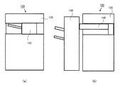
以上、画像形成装置100本体に用紙後処理装置150及び中継搬送パス148が装着された場合の例を説明した。画像形成装置100の本体ファン145及び本体ファン149の制御に関しては、必ずしも用紙後処理装置150及び中継搬送パス148が装着されている場合ばかりではない。例えば、画像形成装置100の排紙トレイ125上方に熱源となるものがある場合は、同様の制御で対応することができる。ここで、図7は画像形成システムの構成例を簡易に示す図である。例えば、本実施の形態の画像形成システムは、図7(b)に示すように、画像形成装置100に中継搬送パス148と用紙後処理装置150が装着されたものである。しかし、図7(a)に示すような構成の画像形成システム、即ち、画像形成装置100の胴内に用紙後処理装置155が装着されている場合でも、上述した制御を適用できる。   The example in which the sheet post-processing device 150 and the relay conveyance path 148 are mounted on the main body of the image forming apparatus 100 has been described above. The control of the main body fan 145 and the main body fan 149 of the image forming apparatus 100 is not necessarily limited to the case where the sheet post-processing device 150 and the relay conveyance path 148 are mounted. For example, when there is a heat source above the paper discharge tray 125 of the image forming apparatus 100, the same control can be used. Here, FIG. 7 is a diagram simply showing a configuration example of the image forming system. For example, as shown in FIG. 7B, the image forming system according to the present embodiment is one in which a relay conveyance path 148 and a sheet post-processing device 150 are mounted on the image forming apparatus 100. However, the above-described control can be applied even when the sheet post-processing device 155 is mounted in the image forming system configured as shown in FIG.

また、本実施の形態では、機外温度センサ141で検知した温度に応じた制御を行っている。しかし、機内温度センサ142で検知した温度に応じてファンの制御を実施することも可能であり、その場合は、図4の温度に、各温度の閾値を例えば2℃、オフセットするなど、使用環境の温度と画像形成装置100内の温度の関係を考慮して調整すればよい。   In the present embodiment, control according to the temperature detected by the external temperature sensor 141 is performed. However, it is also possible to control the fan according to the temperature detected by the in-machine temperature sensor 142. In this case, the operating environment such as offsetting the threshold value of each temperature by 2 ° C., for example, to the temperature shown in FIG. The temperature may be adjusted in consideration of the relationship between the temperature in the image forming apparatus 100 and the temperature in the image forming apparatus 100.

更に、画像形成装置100がスタンバイ状態であるとき、補助電源147の昇温を抑制するために、次のようにすることも効果的である。即ち、用紙後処理装置150の駆動部、例えばトレイを上下移動させるトレイモータ663や、その他パワー系の負荷の状態を維持している電力をオフさせることも効果的である。その際、用紙後処理装置150のステータス(たとえば、扉の開閉やエラー)を把握しておくために、補助電源147から制御部であるASIC661などに供給されているロジック系の電力は供給しておく方がよい。   Further, in order to suppress the temperature rise of the auxiliary power supply 147 when the image forming apparatus 100 is in the standby state, the following is also effective. That is, it is also effective to turn off the drive unit of the sheet post-processing device 150, for example, the tray motor 663 that moves the tray up and down, and other power that maintains the load state of the power system. At that time, in order to keep track of the status of the sheet post-processing device 150 (for example, opening / closing of the door or an error), the logic power supplied from the auxiliary power supply 147 to the ASIC 661 or the like is supplied. It is better to leave.

また、上述した例では、画像形成装置100のCPU601が実行するとして説明したが、中継搬送パス148のCPU651により実行する構成としてもよい。この場合、例えば機外温度センサ141の検知結果はCPU601からCPU651に出力されるものとし、CPU601とCPU651との間で制御に必要な情報の送受信が行われるように構成する。   In the above-described example, the CPU 601 of the image forming apparatus 100 is described as being executed. However, the CPU 651 of the relay conveyance path 148 may be executed. In this case, for example, the detection result of the outside temperature sensor 141 is output from the CPU 601 to the CPU 651, and information necessary for control is transmitted and received between the CPU 601 and the CPU 651.

以上、本実施の形態によれば、ファンの動作音を低減しつつ、トナーボトル回りを冷却しトナーへの熱の影響を低減することができる。   As described above, according to the present embodiment, it is possible to reduce the influence of heat on the toner by cooling the periphery of the toner bottle while reducing the operation noise of the fan.

[第二の実施の形態]
第二の実施の形態は、第一の実施の形態と同様の構成の画像形成装置100における本体ファン145又は中継搬送ファン146の制御に関する。ここで、機内温度センサ142はトナーボトル130周辺の温度によく追従する位置に配置されているものとし、機内温度センサ142で検知された温度に応じて後述するような制御を実行する。
[Second Embodiment]
The second embodiment relates to control of the main body fan 145 or the relay conveyance fan 146 in the image forming apparatus 100 having the same configuration as that of the first embodiment. Here, it is assumed that the in-machine temperature sensor 142 is disposed at a position that closely follows the temperature around the toner bottle 130, and executes control as described later according to the temperature detected by the in-machine temperature sensor 142.

<本体ファン145>
図8は画像形成動作が終了した後、画像形成装置100がスタンバイ状態となっているときの本体ファン145の制御に関し、横軸に時間、縦軸に機内温度を示している。本体ファン145を停止している状態で機内温度が第一の温度である所定の温度T4より低い場合は、本体ファン145をそのまま停止(ファンOFF)させておく。そして、昇温により機内温度が所定の温度T4を超えると本体ファン145を回転駆動(ファンON)させる。このとき、ファンの動作音を考慮して、本体ファン145の速度を例えば半速に落として駆動させる。
<Main unit fan 145>
FIG. 8 shows the control of the main unit fan 145 when the image forming apparatus 100 is in the standby state after the image forming operation is finished, with the horizontal axis indicating time and the vertical axis indicating the in-machine temperature. When the main body fan 145 is stopped and the internal temperature is lower than the predetermined temperature T4 that is the first temperature, the main body fan 145 is stopped (fan OFF) as it is. When the internal temperature exceeds a predetermined temperature T4 due to the temperature rise, the main body fan 145 is driven to rotate (fan ON). At this time, considering the operation sound of the fan, the main fan 145 is driven at a speed of, for example, half speed.

本体ファン145を回転駆動させ、機内温度が所定の温度T4より更に低い第二の温度未満、即ち温度T5未満となったタイミングで、本体ファン145を停止する。そして、再び機内温度が上昇して所定の温度T4を上回ったタイミングで本体ファン145を回転駆動させる。即ち、本体ファン145の駆動を開始させる際の温度の閾値T4と、本体ファン145の駆動を停止させる際の温度の閾値T5とを異ならせて(T4≠T5)、ヒステリシス特性を持たせる構成とする。本実施の形態では、画像形成装置100がスリープ状態に移行した後は、このような制御を繰り返す。ここで、所定の温度T4は例えば38℃で、温度T5は例えば33℃といった温度で、予め決められた値であり、ROM603に予め記憶しておく。このようにファンを回転及び停止する閾値温度を変えて長周期的な制御をすることで、不必要に短期間でファンのオン、オフを繰り返すことを防止できる。これにより放射ノイズに影響を及ぼしたり、ファンの寿命を縮めたり、ファンの回転数が変化して発生する動作音の変化による影響を抑制することができる。   The main body fan 145 is driven to rotate, and the main body fan 145 is stopped at a timing when the internal temperature becomes lower than the second temperature lower than the predetermined temperature T4, that is, lower than the temperature T5. Then, the main body fan 145 is driven to rotate at a timing when the in-machine temperature rises again and exceeds a predetermined temperature T4. That is, the temperature threshold T4 when starting the driving of the main body fan 145 is different from the temperature threshold T5 when stopping the driving of the main body fan 145 (T4 ≠ T5), thereby providing hysteresis characteristics. To do. In the present embodiment, such control is repeated after the image forming apparatus 100 shifts to the sleep state. Here, the predetermined temperature T4 is, for example, 38 ° C., and the temperature T5, for example, 33 ° C., is a predetermined value and is stored in the ROM 603 in advance. Thus, by controlling the long-period control by changing the threshold temperature for rotating and stopping the fan, it is possible to prevent the fan from being repeatedly turned on and off unnecessarily in a short period. As a result, it is possible to suppress the influence due to the change of the operation sound generated by affecting the radiation noise, shortening the life of the fan, or changing the rotation speed of the fan.

<ファンの制御処理>
次に図9のフローチャートを用いて本制御の動作を説明する。なお、図9のS202〜S205の処理は、図5のS102〜S105の処理と同様であり、説明を省略する。S206でCPU601は、全てのファンを停止させる。S207でCPU601は、機内温度センサ142により画像形成装置100内の温度(以下、機内温度とする)を検知する。S208でCPU601は、S207で機内温度センサ142により検知した機内温度に応じて、画像形成装置100がスタンバイ状態となっている間の各ファンの動作を決定し、スタンバイ状態に移行して、ファンの制御を実行する。S208でCPU601が実行する処理は、上述したように図8を用いて説明した本体ファン145のオン、オフの閾値温度を変えた制御に基づくものである。即ち、本体ファン145が停止している状態で、機内温度センサ142の検知温度が閾値温度T4を超えた場合、CPU601は本体ファン145を半速で回転させる。また、本体ファン145が回転している状態で、機内温度センサ142の検知温度が閾値温度T5を下回った場合、CPU601は本体ファン145の回転を停止させる。S209〜S211の処理は、図5のS108〜S110の処理と同様であり、説明を省略する。
<Fan control processing>
Next, the operation of this control will be described using the flowchart of FIG. Note that the processing in S202 to S205 in FIG. 9 is the same as the processing in S102 to S105 in FIG. In S206, the CPU 601 stops all the fans. In step S <b> 207, the CPU 601 detects the temperature in the image forming apparatus 100 (hereinafter referred to as “in-machine temperature”) by the in-machine temperature sensor 142. In step S208, the CPU 601 determines the operation of each fan while the image forming apparatus 100 is in the standby state according to the internal temperature detected by the internal temperature sensor 142 in step S207. Execute control. The processing executed by the CPU 601 in S208 is based on the control in which the on / off threshold temperature of the main body fan 145 described with reference to FIG. 8 is changed as described above. That is, when the temperature detected by the in-machine temperature sensor 142 exceeds the threshold temperature T4 while the main body fan 145 is stopped, the CPU 601 rotates the main body fan 145 at half speed. If the temperature detected by the in-machine temperature sensor 142 falls below the threshold temperature T5 while the main body fan 145 is rotating, the CPU 601 stops the rotation of the main body fan 145. The processing of S209 to S211 is the same as the processing of S108 to S110 in FIG.

ここでは、スタンバイ中の本体ファン145の制御に関して説明したが、必要に応じて中継搬送ファン146、本体ファン149にもそれぞれオン、オフの閾値温度を設定する構成としてもよい。これにより、更に冷却効果を得ることができる。   Here, the control of the main body fan 145 in the standby mode has been described, but it may be configured such that the relay transport fan 146 and the main body fan 149 are set to ON / OFF threshold temperatures as necessary. Thereby, a further cooling effect can be obtained.

以上、本実施の形態によれば、ファンの動作音を低減しつつ、トナーボトル回りを冷却しトナーへの熱の影響を低減することができる。   As described above, according to the present embodiment, it is possible to reduce the influence of heat on the toner by cooling the periphery of the toner bottle while reducing the operation noise of the fan.

[第三の実施の形態]
第三の実施の形態は第一の実施の形態又は第二の実施の形態と同様の構成の画像形成装置100における本体ファン145又は中継搬送ファン146の制御に関する。以下、図10を用いて本実施例の制御を説明する。
[Third embodiment]
The third embodiment relates to control of the main body fan 145 or the relay conveyance fan 146 in the image forming apparatus 100 having the same configuration as that of the first embodiment or the second embodiment. Hereinafter, the control of this embodiment will be described with reference to FIG.

<ファンの制御処理>
S302、S303の処理は、図5のS102、S103の処理と同様であり説明を省略する。S304でCPU601は、本体ファン145を全速で回転させる。なお、本実施の形態では、本体ファン149と中継搬送ファン146は停止している。しかし、本体ファン149と中継搬送ファン146を回転させる構成としてもよい。S305でCPU601は、画像形成動作を終了する。
<Fan control processing>
The processing in S302 and S303 is the same as the processing in S102 and S103 in FIG. In S304, the CPU 601 rotates the main body fan 145 at full speed. In this embodiment, main body fan 149 and relay conveyance fan 146 are stopped. However, the main body fan 149 and the relay transport fan 146 may be rotated. In step S305, the CPU 601 ends the image forming operation.

S306でCPU601は、S302で受信したジョブの中で、用紙後処理装置150を使用したか否かを判断する。CPU601は、S302で受信したジョブの中に含まれている情報に基づいて、用紙後処理装置150を使用したか否かを判断する。CPU601は、用紙後処理装置150を使用したか否かを検知する検知手段としても機能する。S306でCPU601は、用紙後処理装置150を使用したと判断した場合、S307の処理に進む。この場合、中継搬送パス148が昇温し、排紙トレイ125直下のトナーボトル130も影響を受けるおそれがあるため、S307で本体ファン145を半速で回転駆動させて、S308でスタンバイ状態に移行し、タイマをリセットしてスタートさせる。S309でCPU601は、タイマを参照することにより、予め設定された所定時間が経過したか否かを判断し、所定時間が経過していないと判断した場合はS309の処理を繰り返す。   In step S <b> 306, the CPU 601 determines whether the paper post-processing device 150 has been used in the job received in step S <b> 302. The CPU 601 determines whether or not the paper post-processing device 150 has been used based on the information included in the job received in S302. The CPU 601 also functions as a detection unit that detects whether the paper post-processing device 150 has been used. If the CPU 601 determines in step S306 that the sheet post-processing device 150 has been used, the process proceeds to step S307. In this case, the temperature of the relay conveyance path 148 is increased, and the toner bottle 130 directly under the paper discharge tray 125 may be affected. Therefore, the main body fan 145 is rotated at half speed in S307, and the standby state is shifted in S308. Then reset the timer and start it. In step S309, the CPU 601 refers to the timer to determine whether a predetermined time set in advance has elapsed. If it is determined that the predetermined time has not elapsed, the processing in step S309 is repeated.

S309でCPU601は、所定時間が経過したと判断した場合は、トナーボトル130が十分冷却されたと判断し、S310で本体ファン145を停止させて処理を終了する。なお、S309の所定時間は、例えばジョブで指定された画像形成の枚数に応じて決定される。例えば、CPU601は、ジョブの画像形成枚数が少ないほど本体ファン145を回転させる時間を短くしたり、数枚であれば本体ファン145を停止させたりする制御を行い、ジョブの枚数が多いほど本体ファン145を回転させる時間を長くするよう制御する。S306でCPU601は、S302で受信したジョブ中で用紙後処理装置150を使用していないと判断した場合、S311の処理に進む。S311でCPU601は、本体ファン145を停止させ、S312でスタンバイ状態に移行して、処理を終了する。   If the CPU 601 determines in S309 that the predetermined time has elapsed, the CPU 601 determines that the toner bottle 130 is sufficiently cooled, stops the main body fan 145 in S310, and ends the process. Note that the predetermined time in S309 is determined according to the number of image formations specified in the job, for example. For example, the CPU 601 performs control to shorten the time for which the main fan 145 is rotated as the number of job images formed decreases, or to stop the main fan 145 when the number of sheets is increased. Control to increase the time for rotating 145. If the CPU 601 determines in step S306 that the sheet post-processing device 150 is not used in the job received in step S302, the process proceeds to step S311. In step S311, the CPU 601 stops the main fan 145, shifts to a standby state in step S312, and ends the processing.

以上のように、本実施の形態では、用紙後処理装置150が使用されたか否かに応じて、スタンバイ中のファン制御を変更する。これにより、温度検知センサ(機外温度センサ141や機内温度センサ142等)を用いることなく画像形成装置100内のトナーボトル130周辺の冷却を効率よく実施することが可能となる。   As described above, in this embodiment, the standby fan control is changed according to whether or not the sheet post-processing device 150 is used. Accordingly, it is possible to efficiently cool the periphery of the toner bottle 130 in the image forming apparatus 100 without using a temperature detection sensor (such as the outside temperature sensor 141 or the inside temperature sensor 142).

なお、本実施の形態では、画像形成装置100のスタンバイ中に本体ファン145を半速で制御する例を記載したが、冷却能力が更に必要であれば、次のように制御してもよい。即ち、画像形成装置100のスタンバイ中であっても、本体ファン145を全速で回転させる、中継搬送ファン146を半速又は全速で駆動させる、本体ファン149を半速又は全速で駆動させる、というような制御を実施すればよい。   In the present embodiment, the example in which main body fan 145 is controlled at half speed during standby of image forming apparatus 100 has been described. However, if cooling capacity is further required, control may be performed as follows. That is, even when the image forming apparatus 100 is on standby, the main body fan 145 is rotated at full speed, the relay conveyance fan 146 is driven at half speed or full speed, and the main body fan 149 is driven at half speed or full speed. What is necessary is just to implement a control.

以上、本実施の形態によれば、ファンの動作音を低減しつつ、トナーボトル回りを冷却しトナーへの熱の影響を低減することができる。   As described above, according to the present embodiment, it is possible to reduce the influence of heat on the toner by cooling the periphery of the toner bottle while reducing the operation noise of the fan.

141 機外温度センサ
142 機内温度センサ
145、149 本体ファン
146 中継搬送ファン
601 CPU
141 Outside temperature sensor 142 Inside temperature sensor 145, 149 Main body fan 146 Relay transfer fan 601 CPU

Claims (13)

現像剤を収容する収容容器と、
前記収容容器から供給される現像剤を用いて記録材に画像を形成する画像形成部と、
前記画像形成部により画像が形成された記録材を排出する排出部と、を備え、
記録材に後処理を行う後処理装置が接続される場合に前記排出部から排出される記録材を前記後処理装置へ搬送するための中継搬送部を前記排出部に隣接する空間に装着され、前記中継搬送部には前記中継搬送部に電力を供給する電源が前記収容容器の上部に設けられ、前記電源の発熱が前記収容容器の温度に関与する画像形成装置であって、
温度を検知する検知手段と、
前記画像形成部を冷却するための第一の冷却手段と、
前記中継搬送部が装着されている場合に、前記画像形成部により記録材に画像を形成している第一の状態の後の記録材に画像を形成する動作の開始を待機している第二の状態では、前記検知手段により検知した温度が第一の温度であれば前記第一の冷却手段を停止させ、前記第一の温度よりも高い第二の温度であれば、前記第一の冷却手段を回転させるよう制御し、前記中継搬送部が装着されていない場合に、前記検知手段により検知される温度が前記第一の温度と前記第二の温度の何れでも前記第一の冷却手段を停止させるよう制御する制御手段と、
を備えることを特徴とする画像形成装置。
A container for containing the developer;
An image forming unit that forms an image on a recording material using a developer supplied from the container ;
A discharge section for discharging the recording material on which an image is formed by the image forming section,
When a post-processing device that performs post-processing is connected to the recording material, a relay transport unit for transporting the recording material discharged from the discharge unit to the post-processing device is mounted in a space adjacent to the discharge unit, The relay transport unit is provided with a power source for supplying power to the relay transport unit at an upper portion of the container, and the heat generation of the power source is related to the temperature of the container ,
Detecting means for detecting temperature;
A first cooling means for cooling the image forming unit;
When the relay conveyance unit is mounted, the second waiting for the start of the operation of forming an image on the recording material after the first state in which the image forming unit forms an image on the recording material. In this state, if the temperature detected by the detection means is the first temperature, the first cooling means is stopped, and if the temperature is a second temperature higher than the first temperature , the first cooling is performed. controlled to rotate the unit, when the relay conveying unit is not attached, the either the first cooling means temperature detected said first temperature and said second temperature by said detecting means Control means for controlling to stop ;
An image forming apparatus comprising:
前記制御手段は、前記中継搬送部が装着されていない場合に、前記第二の状態では、前記検知手段により検知される温度にかかわらず前記第一の冷却手段を停止させることを特徴とする請求項1に記載の画像形成装置。 The control means stops the first cooling means in the second state regardless of the temperature detected by the detection means when the relay conveyance section is not mounted. Item 2. The image forming apparatus according to Item 1. 前記検知手段は、前記画像形成装置が使用されている環境の温度を検知することを特徴とする請求項1又は2に記載の画像形成装置。   The image forming apparatus according to claim 1, wherein the detection unit detects a temperature of an environment where the image forming apparatus is used. 前記検知手段は、前記画像形成装置の内部で前記画像形成部の近傍の温度を検知することを特徴とする請求項1又は2に記載の画像形成装置。   The image forming apparatus according to claim 1, wherein the detection unit detects a temperature in the vicinity of the image forming unit inside the image forming apparatus. 前記中継搬送部は、前記電源を冷却する第二の冷却手段を有することを特徴とする請求項1乃至4のいずれか1項に記載の画像形成装置。   The image forming apparatus according to claim 1, wherein the relay conveyance unit includes a second cooling unit that cools the power source. 前記制御手段は、前記中継搬送部が装着されている場合、前記第二の状態では、前記検知手段により検知した温度が前記第二の温度であれば、前記第二の冷却手段の回転を停止させ、前記第二の温度よりも高い第三の温度であれば、前記第二の冷却手段を回転させることを特徴とする請求項5に記載の画像形成装置。 Wherein, when the relay conveying unit is mounted, wherein in the second state, if the temperature is the second temperature that is detected by the detecting means, the rotation of the second cooling unit is stopped, if high a third temperature than the second temperature, the image forming apparatus according to claim 5, characterized in Rukoto rotates the second cooling unit. 前記画像形成部を駆動する駆動手段を冷却する第三の冷却手段を備え、
前記制御手段は、前記中継搬送部が装着されている場合、前記第二の状態では、前記検知手段により検知した温度が前記第の温度であれば、記第三の冷却手段の回転を停止させ、前記第三の温度よりも高い第四の温度であれば、前記第三の冷却手段を回転させることを特徴とする請求項6に記載の画像形成装置。
A third cooling means for cooling the drive means for driving the image forming unit;
Wherein, when the relay conveying unit is mounted, wherein in the second state, if the temperature is the third temperature that is detected by the detecting means, the rotation of the pre-Symbol third cooling means is stopped, if high a fourth temperature than the third temperature, the image forming apparatus according to claim 6, characterized in Rukoto rotates the third cooling means.
前記制御手段は、前記中継搬送部が装着されている場合、前記第二の状態では、前記検知手段により検知した温度が前記第一の温度よりも高く前記第二の温度よりも低い第五の温度であれば、前記第一の冷却手段を回転させる動作と前記第一の冷却手段の回転を停止させる動作を繰り返すことを特徴とする請求項6に記載の画像形成装置。 Wherein, when the relay conveying unit is mounted, wherein in the second state, temperature detected by said detecting means fifth lower than the higher the second temperature than said first temperature if the temperature, the image forming apparatus according to claim 6, characterized in that operation is repeated to stop the rotation of the operation and the first cooling means for rotating said first cooling means. 前記制御手段は、前記中継搬送部が装着されている場合、前記第二の状態では、前記検知手段により検知した温度が前記第二の温度、前記第三の温度及び前記第四の温度である場合の前記第一の冷却手段の回転速度よりも、前記第四の温度よりも高い第六の温度である場合の前記第一の冷却手段の回転速度を速くすることを特徴とする請求項7に記載の画像形成装置。In the second state, when the relay conveyance unit is mounted, the control unit detects the second temperature, the third temperature, and the fourth temperature in the second state. The rotational speed of the first cooling means when the sixth temperature is higher than the fourth temperature is made faster than the rotational speed of the first cooling means in this case. The image forming apparatus described in 1. 前記制御手段は、前記中継搬送部が装着されている場合、前記第二の状態では、前記検知手段により検知した温度が前記第三の温度及び前記第四の温度である場合の前記第二の冷却手段の回転速度よりも、前記第六の温度である場合の前記第二の冷却手段の回転速度を速くすることを特徴とする請求項9に記載の画像形成装置。In the second state, when the relay transport unit is mounted, the control unit is configured to detect the second temperature when the temperature detected by the detection unit is the third temperature and the fourth temperature. The image forming apparatus according to claim 9, wherein a rotation speed of the second cooling unit when the temperature is the sixth temperature is made faster than a rotation speed of the cooling unit. 前記制御手段は、前記中継搬送部が装着されている場合、前記第二の状態では、前記検知手段により検知した温度が前記第一の温度よりも高く前記第二の温度よりも低い第五の温度である場合に前記第一の冷却手段を回転させるときの回転速度よりも、前記第四の温度よりも高い第六の温度である場合の前記第一の冷却手段の回転速度を速くすることを特徴とする請求項7に記載の画像形成装置。In the second state, when the relay transport unit is mounted, the control means has a fifth temperature detected by the detection means that is higher than the first temperature and lower than the second temperature. Increasing the rotational speed of the first cooling means when the temperature is the sixth temperature higher than the fourth temperature than the rotational speed when rotating the first cooling means when the temperature is The image forming apparatus according to claim 7. 前記制御手段は、前記中継搬送部が装着されている場合、前記第一の状態では、前記検知手段が検知した温度が前記第四の温度以下において前記第一の冷却手段、前記第二の冷却手段及び前記第三の冷却手段の回転速度を、前記第二の状態で前記第一の冷却手段を回転させるときの回転速度よりも速くすることを特徴とする請求項7に記載の画像形成装置。In the first state, when the relay conveyance unit is mounted, the control means is configured such that, in the first state, the first cooling means and the second cooling when the temperature detected by the detection means is equal to or lower than the fourth temperature. The image forming apparatus according to claim 7, wherein rotation speeds of the first cooling unit and the third cooling unit are made faster than a rotation speed when the first cooling unit is rotated in the second state. . 原稿の画像を読み取る読取部を有し、前記中継搬送部は前記読取部と前記画像形成部との間に形成される空間に装着されることを特徴とする請求項1乃至12のいずれか1項に記載の画像形成装置。 It has a reading unit reading an image of a document, either the relay conveying unit according to claim 1 to 12, characterized in that it is mounted in a space formed between the image forming unit and the reading unit 1 The image forming apparatus described in the item.
JP2014207388A 2014-10-08 2014-10-08 Image forming apparatus Active JP6422295B2 (en)

Priority Applications (2)

Application Number Priority Date Filing Date Title
JP2014207388A JP6422295B2 (en) 2014-10-08 2014-10-08 Image forming apparatus
US14/873,767 US9910407B2 (en) 2014-10-08 2015-10-02 Image forming apparatus and image forming system

Applications Claiming Priority (1)

Application Number Priority Date Filing Date Title
JP2014207388A JP6422295B2 (en) 2014-10-08 2014-10-08 Image forming apparatus

Publications (3)

Publication Number Publication Date
JP2016075850A JP2016075850A (en) 2016-05-12
JP2016075850A5 JP2016075850A5 (en) 2017-11-16
JP6422295B2 true JP6422295B2 (en) 2018-11-14

Family

ID=55951251

Family Applications (1)

Application Number Title Priority Date Filing Date
JP2014207388A Active JP6422295B2 (en) 2014-10-08 2014-10-08 Image forming apparatus

Country Status (2)

Country Link
US (1) US9910407B2 (en)
JP (1) JP6422295B2 (en)

Families Citing this family (3)

* Cited by examiner, † Cited by third party
Publication number Priority date Publication date Assignee Title
DK2885031T3 (en) 2012-08-20 2018-01-08 Sanofi Aventis Deutschland PHARMACEUTICAL DISPENSER DEVICE AND PROCEDURE FOR ELECTRIC DETECTION OF CONTACT BETWEEN Piston Rod and Cartridge Plug
DE102013221516A1 (en) * 2013-10-23 2015-04-23 Bayerische Motoren Werke Aktiengesellschaft An air supply device for a vehicle seat and method for operating the air supply device
JP6922719B2 (en) * 2017-12-19 2021-08-18 ブラザー工業株式会社 Image forming device

Family Cites Families (15)

* Cited by examiner, † Cited by third party
Publication number Priority date Publication date Assignee Title
JPH04163473A (en) * 1990-10-26 1992-06-09 Toshiba Corp Picture forming device
JPH09204115A (en) * 1996-01-25 1997-08-05 Fuji Xerox Co Ltd Image forming device
US6594456B2 (en) * 2000-07-26 2003-07-15 Canon Kabushiki Kaisha Image forming apparatus
JP2002036662A (en) * 2000-07-28 2002-02-06 Murata Mach Ltd Electronic apparatus
JP3901459B2 (en) * 2001-02-16 2007-04-04 株式会社リコー Image forming apparatus
JP2002370862A (en) 2001-06-11 2002-12-24 Fuji Xerox Co Ltd Image forming device
JP2004117732A (en) * 2002-09-25 2004-04-15 Canon Inc Image forming apparatus and its control method, control program, and storage medium
JP4332366B2 (en) * 2003-04-07 2009-09-16 キヤノン株式会社 Image forming apparatus
KR20070000595A (en) * 2005-06-28 2007-01-03 삼성전자주식회사 Fuser cooling fan control method and image forming apparatus having the same
JP2007333796A (en) * 2006-06-12 2007-12-27 Canon Inc Image reading/forming apparatus
JP2007164211A (en) * 2007-02-05 2007-06-28 Ricoh Co Ltd Image forming apparatus
JP2010175715A (en) * 2009-01-28 2010-08-12 Ricoh Co Ltd Controller for cooling fan, image forming apparatus, cooling control method of electronic apparatus, and cooling control program
JP5521765B2 (en) * 2010-05-19 2014-06-18 コニカミノルタ株式会社 Image forming apparatus
JP5195839B2 (en) * 2010-07-29 2013-05-15 コニカミノルタビジネステクノロジーズ株式会社 Image forming apparatus and fan drive control method in the same
JP5675709B2 (en) * 2012-06-15 2015-02-25 京セラドキュメントソリューションズ株式会社 Sheet conveying apparatus and image forming apparatus

Also Published As

Publication number Publication date
JP2016075850A (en) 2016-05-12
US20170096314A1 (en) 2017-04-06
US9910407B2 (en) 2018-03-06

Similar Documents

Publication Publication Date Title
JP5863011B2 (en) Image forming apparatus
US9213253B2 (en) Image forming apparatus having image carrier and belt member
JP6103358B2 (en) Image forming apparatus
JP6422295B2 (en) Image forming apparatus
JP2013065019A (en) Image formation device
JP2000330426A (en) Electrophotographic device
JP2013225108A (en) Image forming apparatus
JP6200834B2 (en) Image forming apparatus
JP6039230B2 (en) Image forming apparatus
US20180074446A1 (en) Image forming apparatus
JP2006091510A (en) Image forming apparatus
US20160139552A1 (en) Image forming apparatus, control method of contacting/separating state of component
JP2018004705A (en) Image forming apparatus
JP2007025205A (en) Image forming apparatus and its control method
JP2016130830A (en) Image forming apparatus
JP2006350161A (en) Image forming apparatus
US8977152B2 (en) Image forming apparatus having developer stirring control
JP5073586B2 (en) Image forming apparatus
JP4710346B2 (en) Image forming apparatus and color misregistration correction method
JP7087914B2 (en) Image forming device
JP2012137520A (en) Image forming apparatus
JP2010149451A (en) Power consumption calculator
JP2016105155A (en) Image forming apparatus and method for controlling contact/separation state of component
JP2007322987A (en) Cleaning system, fixing device, and image forming apparatus
JP2012088625A (en) Image forming apparatus

Legal Events

Date Code Title Description
RD03 Notification of appointment of power of attorney

Free format text: JAPANESE INTERMEDIATE CODE: A7423

Effective date: 20160215

RD04 Notification of resignation of power of attorney

Free format text: JAPANESE INTERMEDIATE CODE: A7424

Effective date: 20160215

A521 Request for written amendment filed

Free format text: JAPANESE INTERMEDIATE CODE: A523

Effective date: 20171005

A621 Written request for application examination

Free format text: JAPANESE INTERMEDIATE CODE: A621

Effective date: 20171005

RD04 Notification of resignation of power of attorney

Free format text: JAPANESE INTERMEDIATE CODE: A7424

Effective date: 20171201

A131 Notification of reasons for refusal

Free format text: JAPANESE INTERMEDIATE CODE: A131

Effective date: 20180612

A977 Report on retrieval

Free format text: JAPANESE INTERMEDIATE CODE: A971007

Effective date: 20180613

A521 Request for written amendment filed

Free format text: JAPANESE INTERMEDIATE CODE: A523

Effective date: 20180810

TRDD Decision of grant or rejection written
A01 Written decision to grant a patent or to grant a registration (utility model)

Free format text: JAPANESE INTERMEDIATE CODE: A01

Effective date: 20180918

A61 First payment of annual fees (during grant procedure)

Free format text: JAPANESE INTERMEDIATE CODE: A61

Effective date: 20181016

R151 Written notification of patent or utility model registration

Ref document number: 6422295

Country of ref document: JP

Free format text: JAPANESE INTERMEDIATE CODE: R151