JP6421149B2 - Optical connector and optical connector connection method - Google Patents
Optical connector and optical connector connection method Download PDFInfo
- Publication number
- JP6421149B2 JP6421149B2 JP2016171770A JP2016171770A JP6421149B2 JP 6421149 B2 JP6421149 B2 JP 6421149B2 JP 2016171770 A JP2016171770 A JP 2016171770A JP 2016171770 A JP2016171770 A JP 2016171770A JP 6421149 B2 JP6421149 B2 JP 6421149B2
- Authority
- JP
- Japan
- Prior art keywords
- plug
- receptacle
- optical
- housing
- ferrule
- Prior art date
- Legal status (The legal status is an assumption and is not a legal conclusion. Google has not performed a legal analysis and makes no representation as to the accuracy of the status listed.)
- Active
Links
Images


Description
本開示は、光コネクタ及び光コネクタの接続方法に関する。 The present disclosure relates to an optical connector and an optical connector connection method.
フェルールを後退可能にハウジングに収容した光コネクタの一例として、例えばMT形光コネクタ(JIS C5981に制定されるF12形光コネクタ。MT:Mechanically Transferable)が知られている。このような光コネクタでは、複数の光ファイバを保持するフェルールの端面同士が突き当たることによって、光ファイバの端面同士が物理的に突き当たり、光ファイバ同士が光接続される。 As an example of an optical connector in which a ferrule is accommodated in a retractable housing, for example, an MT type optical connector (F12 type optical connector established in JIS C5981; MT: Mechanically Transferable) is known. In such an optical connector, the end faces of the ferrules holding a plurality of optical fibers abut against each other so that the end faces of the optical fibers physically abut against each other and the optical fibers are optically connected.
FTTH(Fiber to the Home)サービスにおける局舎と局舎外部のクロージャとの間で、例えば1000心や2000心などの多心の光ファイバを光接続することがある。この際、従来では、このような多心の光ファイバをいくつかの束ごとに分岐して、クロージャ内で融着することで接続していたため、接続作業に多大な手間がかかっていた。 In some cases, multi-core optical fibers such as 1000 cores and 2000 cores are optically connected between a station building and a closure outside the station in an FTTH (Fiber to the Home) service. At this time, conventionally, such a multi-fiber optical fiber is branched into several bundles and connected by fusing within a closure, so that much work is required for the connection work.
また、MT形光コネクタを利用して接続する場合には、一つのフェルールにおけるプッシュバック量が限定されていたため、このような多心の光ファイバを複数のフェルールで一括して接続する際には、複数のフェルール間の寸法公差が無視できなかった。また、フェルールのプッシュバック量で寸法公差を吸収しようとすると、フェルールごとに押圧量が異なってしまったり、プッシュバック量を長く設定する必要が生じたりするという問題も生じてしまう。 Also, when connecting using an MT type optical connector, the amount of pushback in one ferrule is limited, so when connecting such multi-fiber optical fibers in a batch with a plurality of ferrules The dimensional tolerance between the ferrules could not be ignored. Further, when trying to absorb the dimensional tolerance by the pushback amount of the ferrule, there arises a problem that the pressing amount is different for each ferrule or the pushback amount needs to be set longer.
本発明の幾つかの実施形態は、高密度多心光ファイバ同士を接続する複数のフェルールを一括接続できる光コネクタを提供することを目的とする。 An object of some embodiments of the present invention is to provide an optical connector that can collectively connect a plurality of ferrules that connect high-density multi-core optical fibers.
上記課題を解決するための幾つかの実施形態は、着脱可能な光レセプタクルと光プラグとを有する光コネクタであって、前記光レセプタクルは、外部ハウジングと、内部ハウジングと、前記内部ハウジングに収容されたレセプタクル側フェルールと、前記レセプタクル側フェルールに押圧力を付与するレセプタクル側バネと、を有するレセプタクル側コネクタモジュールを複数備え、前記光プラグは、プラグ側ハウジングと、前記プラグ側ハウジングに収容されたプラグ側フェルールと、前記プラグ側フェルールに押圧力を付与するプラグ側バネと、を有するプラグ側コネクタモジュールを複数備え、前記内部ハウジングは係合部を有し、前記プラグ側ハウジングは被係合部を有し、前記係合部と前記被係合部とが係合した状態では、前記内部ハウジングと前記プラグ側ハウジングとが所定の位置関係になり、前記レセプタクル側バネと前記プラグ側バネとによって前記レセプタクル側フェルールと前記プラグ側フェルールとが所定の押圧力で突き合わされた状態になり、前記プラグ側ハウジングは係止解除部を有し、前記係止解除部が、前記内部ハウジングが前記外部ハウジングに係止された係止状態から係止解除状態にすると、前記内部ハウジングが前記外部ハウジングに対して移動可能になり、前記光レセプタクルは、外周にネジ部が形成されたレセプタクル側円筒部を備え、前記光プラグは、前記レセプタクル側円筒部に螺合するナット部を備え、前記光レセプタクルと前記光プラグとを接続する際に、前記レセプタクル側円筒部と前記ナット部との螺合を進めることにより、それぞれの前記レセプタクル側コネクタモジュール及び前記プラグ側コネクタモジュールにおいて、前記係止状態から前記係止解除状態になった後、前記係合部と前記被係合部とが係合した状態で、前記内部ハウジングと前記プラグ側ハウジングとが前記外部ハウジングに対して着脱方向に移動することを特徴とする光コネクタである。 Some embodiments for solving the above-described problems are optical connectors each having a detachable optical receptacle and an optical plug, and the optical receptacle is accommodated in an external housing, an internal housing, and the internal housing. A plurality of receptacle-side connector modules each having a receptacle-side ferrule and a receptacle-side spring that applies a pressing force to the receptacle-side ferrule. The optical plug includes a plug-side housing and a plug accommodated in the plug-side housing. A plurality of plug-side connector modules each having a side ferrule and a plug-side spring that applies a pressing force to the plug-side ferrule, the inner housing has an engaging portion, and the plug-side housing has an engaged portion. In the state where the engaging portion and the engaged portion are engaged, The housing and the plug-side housing are in a predetermined positional relationship, and the receptacle-side ferrule and the plug-side ferrule are brought into contact with each other with a predetermined pressing force by the receptacle-side spring and the plug-side spring, The plug-side housing has an unlocking portion, and when the unlocking portion changes from the locked state in which the inner housing is locked to the outer housing to the unlocked state, the inner housing is connected to the outer housing. The optical receptacle includes a receptacle-side cylindrical portion having a thread portion formed on an outer periphery thereof, and the optical plug includes a nut portion that is screwed to the receptacle-side cylindrical portion, and the optical receptacle when connecting the optical plug, to advance the screwing between the nut part and the receptacle-side cylinder portion , In each of the receptacle connector module and the plug-side connector module, after becoming the unlocking state from the latched state, in a state in which the said engaging portion and the engaged portion engaged, the The optical connector is characterized in that an inner housing and the plug-side housing move in an attaching / detaching direction with respect to the outer housing.
その他の特徴については、後述する明細書及び図面の記載により明らかにする。 Other features will be clarified in the description and drawings described later.
本発明の幾つかの実施形態によれば、高密度多心光ファイバ同士を接続する複数のフェルールを一括接続することができる。 According to some embodiments of the present invention, a plurality of ferrules that connect high-density multi-core optical fibers can be collectively connected.
後述する明細書及び図面の記載から、少なくとも以下の事項が明らかとなる。 At least the following matters will be apparent from the description and drawings described below.
着脱可能な光レセプタクルと光プラグとを有する光コネクタであって、前記光レセプタクルは、外部ハウジングと、内部ハウジングと、前記内部ハウジングに収容されたレセプタクル側フェルールと、前記レセプタクル側フェルールに押圧力を付与するレセプタクル側バネと、を有するレセプタクル側コネクタモジュールを複数備え、前記光プラグは、プラグ側ハウジングと、前記プラグ側ハウジングに収容されたプラグ側フェルールと、前記プラグ側フェルールに押圧力を付与するプラグ側バネと、を有するプラグ側コネクタモジュールを複数備え、前記内部ハウジングは係合部を有し、前記プラグ側ハウジングは被係合部を有し、前記係合部と前記被係合部とが係合した状態では、前記内部ハウジングと前記プラグ側ハウジングとが所定の位置関係になり、前記レセプタクル側バネと前記プラグ側バネとによって前記レセプタクル側フェルールと前記プラグ側フェルールとが所定の押圧力で突き合わされた状態になり、前記プラグ側ハウジングは係止解除部を有し、前記係止解除部が、前記内部ハウジングが前記外部ハウジングに係止された係止状態から係止解除状態にすると、前記内部ハウジングが前記外部ハウジングに対して移動可能になり、前記光レセプタクルと前記光プラグとを接続する際に、それぞれのレセプタクル側コネクタモジュール及びプラグ側コネクタモジュールにおいて、前記係止状態から前記係止解除状態になった後、前記係合部と前記被係合部とが係合した状態で、前記内部ハウジングと前記プラグ側ハウジングとが前記外部ハウジングに対して着脱方向に移動することを特徴とする光コネクタが明らかとなる。このような光コネクタによれば、高密度多心光ファイバ同士を接続する複数のフェルールを一括接続することができる。 An optical connector having a detachable optical receptacle and an optical plug, the optical receptacle including an external housing, an internal housing, a receptacle-side ferrule accommodated in the internal housing, and a pressing force applied to the receptacle-side ferrule A plurality of receptacle-side connector modules each having a receptacle-side spring to be applied; and the optical plug applies a pressing force to the plug-side housing, the plug-side ferrule accommodated in the plug-side housing, and the plug-side ferrule. A plurality of plug-side connector modules each having a plug-side spring, the inner housing has an engaging portion, the plug-side housing has an engaged portion, and the engaging portion and the engaged portion; In the engaged state, the inner housing and the plug-side housing are predetermined. The receptacle-side spring and the plug-side spring cause the receptacle-side ferrule and the plug-side ferrule to abut against each other with a predetermined pressing force, and the plug-side housing has an unlocking portion. When the unlocking portion changes from the locked state in which the inner housing is locked to the outer housing to the unlocked state, the inner housing becomes movable relative to the outer housing, and the optical receptacle And when connecting the optical plug to the receptacle-side connector module and the plug-side connector module, the engagement portion and the engaged portion are changed from the locked state to the locked state. The inner housing and the plug-side housing are attached to and detached from the outer housing in a state in which Optical connector thus being moved countercurrently becomes apparent. According to such an optical connector, it is possible to collectively connect a plurality of ferrules that connect high-density multi-core optical fibers.
前記光レセプタクルは、外周にネジ部が形成されたレセプタクル側円筒部を備え、前記光プラグは、前記レセプタクル側円筒部に螺合するナット部を備え、前記レセプタクル側円筒部と前記ナット部との螺合を進めることにより、前記係止状態から前記係止解除状態とすることが望ましい。これにより、ねじ緩め動作という簡易な作業を行うだけで、容易に高密度多心光ファイバ同士を接続する複数のフェルールを一括に接続を解除することができる。 The optical receptacle includes a receptacle-side cylindrical portion having a thread portion formed on an outer periphery thereof, and the optical plug includes a nut portion that is screwed to the receptacle-side cylindrical portion, and the receptacle-side cylindrical portion and the nut portion It is desirable to change from the locked state to the unlocked state by advancing the screwing. As a result, it is possible to easily disconnect a plurality of ferrules that connect high-density multi-core optical fibers together simply by performing a simple operation of screw loosening.
前記光プラグは、前記レセプタクル側円筒部の内部に嵌合するプラグ側円筒部を備えることが望ましい。これにより、レセプタクル側ハウジングとプラグ側ハウジングとの嵌合前の粗い位置決めをすることができる。 The optical plug preferably includes a plug-side cylindrical portion that fits inside the receptacle-side cylindrical portion. Thereby, rough positioning can be performed before the receptacle-side housing and the plug-side housing are fitted together.
前記光レセプタクルは、前記外部ハウジングを保持する筐体を備え、前記外部ハウジングは、前記筐体に対して着脱方向に垂直な方向に移動可能に設けられていることが望ましい。これにより、光コネクタ接続時のレセプタクル側ハウジングとプラグ側ハウジングとの相対的な位置ずれを吸収することができる。 The optical receptacle preferably includes a housing that holds the external housing, and the external housing is provided to be movable in a direction perpendicular to the attaching / detaching direction with respect to the housing. As a result, it is possible to absorb the relative displacement between the receptacle-side housing and the plug-side housing when the optical connector is connected.
前記レセプタクル側フェルールと前記プラグ側フェルールとは、レンズ結合型のフェルールであることが望ましい。これにより、フェルールを弾性付勢するためのばねの押圧力を小さくできる。 The receptacle-side ferrule and the plug-side ferrule are preferably lens-coupled ferrules. Thereby, the pressing force of the spring for elastically urging the ferrule can be reduced.
着脱可能な光レセプタクルと光プラグとを有する光コネクタの接続方法であって、前記光レセプタクルは、外部ハウジングと、内部ハウジングと、前記内部ハウジングに収容されたレセプタクル側フェルールと、前記レセプタクル側フェルールに押圧力を付与するレセプタクル側バネと、を有するレセプタクル側コネクタモジュールを複数備え、前記光プラグは、プラグ側ハウジングと、前記プラグ側ハウジングに収容されたプラグ側フェルールと、前記プラグ側フェルールに押圧力を付与するプラグ側バネと、を有するプラグ側コネクタモジュールを複数備え、前記内部ハウジングは係合部を有し、前記プラグ側ハウジングは被係合部を有し、前記係合部と前記被係合部とが係合した状態では、前記内部ハウジングと前記プラグ側ハウジングとが所定の位置関係になり、前記レセプタクル側バネと前記プラグ側バネとによって前記レセプタクル側フェルールと前記プラグ側フェルールとが所定の押圧力で突き合わされた状態になり、前記プラグ側ハウジングは係止解除部を有し、前記係止解除部が、前記内部ハウジングが前記外部ハウジングに係止された係止状態から係止解除状態にすると、前記内部ハウジングが前記外部ハウジングに対して移動可能になり、前記光レセプタクルと前記光プラグとを接続する際に、それぞれのレセプタクル側コネクタモジュール及びプラグ側コネクタモジュールにおいて、前記係止状態から前記係止解除状態になった後、前記係合部と前記被係合部とが係合した状態で、前記内部ハウジングと前記プラグ側ハウジングとが前記外部ハウジングに対して着脱方向に移動することを特徴とする光コネクタの接続方法が明らかとなる。このような光コネクタの接続方法によれば、高密度多心光ファイバ同士を接続する複数のフェルールを一括接続することができる。 A method of connecting an optical connector having a detachable optical receptacle and an optical plug, wherein the optical receptacle includes an external housing, an internal housing, a receptacle-side ferrule accommodated in the internal housing, and the receptacle-side ferrule. A plurality of receptacle-side connector modules each having a receptacle-side spring for applying a pressing force, and the optical plug includes a plug-side housing, a plug-side ferrule accommodated in the plug-side housing, and a pressing force applied to the plug-side ferrule A plurality of plug-side connector modules having a plug-side spring, the inner housing having an engaging portion, the plug-side housing having an engaged portion, and the engaging portion and the engaged portion. In the state where the joint portion is engaged, the inner housing and the plug-side housing And the receptacle-side spring and the plug-side spring are brought into contact with the receptacle-side ferrule and the plug-side ferrule with a predetermined pressing force, and the plug-side housing is locked. When the lock release portion has a lock release state from the lock state in which the internal housing is locked to the external housing, the internal housing becomes movable with respect to the external housing. When the optical receptacle and the optical plug are connected, in each of the receptacle-side connector module and the plug-side connector module, after the locked state is changed to the unlocked state, the engaging portion and the covered portion are connected. With the engagement portion engaged, the inner housing and the plug-side housing are connected to the outer housing. Connection of the optical connector, characterized in that to move the detaching direction is apparent. According to such an optical connector connection method, a plurality of ferrules connecting high-density multi-core optical fibers can be connected together.
===第1実施形態===
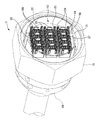
図1は、光レセプタクル2と光プラグ3とを結合する前の光コネクタ1の斜視図である。図2は、光レセプタクル2のレセプタクル側コネクタモジュール11部分を拡大した斜視図である。図3は、光プラグ3のプラグ側コネクタモジュール12部分を拡大した斜視図である。本実施形態では、図1〜図3に示す光コネクタ1の基本的な構成を説明する。
=== First Embodiment ===
FIG. 1 is a perspective view of the optical connector 1 before the
以下の説明では、図1に示すように各方向を定義する。すなわち、光コネクタ1の着脱方向を「前後方向」とし、光レセプタクル2の側を「前」とし、逆側(光プラグ3の側)を「後」とする。前後方向のことを「Z方向」又は「着脱方向」と呼ぶこともある。また、レセプタクル側円筒部6内面の平坦部7Aを含む面において、前後方向に垂直な方向を「左右方向」とし、レセプタクル側コネクタモジュール11の接続端面に向かって右側を「右」とし、左側を「左」とする。左右方向のことを「X方向」と呼ぶこともある。また、前後方向及び左右方向に垂直な方向を「上下方向」とし、レセプタクル側円筒部6のレセプタクル側凹部8の側を「下」とし、逆側(レセプタクル側凸部9の側)を「上」とする。上下方向のことを「Y方向」と呼ぶこともある。
In the following description, each direction is defined as shown in FIG. That is, the direction in which the optical connector 1 is attached / detached is “front / rear direction”, the
<光コネクタ1の基本構成>
光コネクタ1は、高密度多心光ファイバを接続するためのコネクタである。「高密度多心光ファイバ」とは、例えば、1000心や2000心などの多数の心数を有する光ファイバ束を指す。この高密度多心光ファイバ同士を複数のコネクタモジュールを用いて接続する光コネクタを「高密度多心光コネクタ」と呼ぶ。図1の光コネクタ1は、一例として2000心の光ファイバを接続する際の高密度多心光コネクタを示している。なお、本実施形態での「高密度多心」は、1000心や2000心といった特定の心数に限られず、相当数多くの心数のことを指す場合がある。
<Basic configuration of optical connector 1>
The optical connector 1 is a connector for connecting a high density multi-core optical fiber. The “high density multi-fiber optical fiber” refers to an optical fiber bundle having a large number of cores such as 1000 cores and 2000 cores. An optical connector that connects the high-density multi-core optical fibers using a plurality of connector modules is referred to as a “high-density multi-core optical connector”. The optical connector 1 of FIG. 1 shows a high density multi-fiber optical connector when connecting 2000 optical fibers as an example. The “high density multi-core” in the present embodiment is not limited to a specific number of hearts such as 1000 or 2000, but may refer to a considerably large number of hearts.
光コネクタ1は、光レセプタクル2と、光プラグ3とを有する。
The optical connector 1 includes an
光レセプタクル2は、コネクタモジュール10同士の接続の際に、受け側となるレセプタクル側コネクタモジュール11を含む。光レセプタクル2は、光プラグ3との嵌合により、コネクタモジュール10同士を接続することができる。なお、実際の接続作業では、作業者は、例えば光レセプタクル2を右手に、光プラグ3を左手に持って、光レセプタクル2と光プラグ3とをお互いに近づけるようにして嵌合させる。したがって、「レセプタクル側」又は「受け側」とは、便宜的な意味であり、後述する「プラグ側」又は「可動側」に対して必ずしも可動しない側(受ける側)として限定されるものではない。
The
光レセプタクル2は、把持部5と、レセプタクル側円筒部6と、光ファイバ保持部4Aと、レセプタクル側コネクタモジュール11とを有する。
The
把持部5は、光プラグ3との着脱を行う際に、光レセプタクル2を把持することができる部位である。把持部5は、後述する光プラグ3のナット部19と同様に、六角柱の形状をしている。したがって、光レセプタクル2と光プラグ3との着脱を行う際に、作業者は光プラグ3側(後述するナット部19)と、光レセプタクル2側(把持部5)との両方のスパナを回して締め付け作業を行うことができる。これにより、光レセプタクル2と光プラグ3との締め付けトルクが増加し、接続作業の作業効率が向上する。
The
レセプタクル側円筒部6は、後述する光プラグ3のプラグ側円筒部20がレセプタクル側円筒部6の内側に嵌合し、コネクタモジュール10同士が接続する前に粗い位置決めをすることができる部位である。レセプタクル側円筒部6の内径は、プラグ側円筒部20がぐらつかず精度よく嵌合するように、プラグ側円筒部20の外径よりわずかに大きくなっている。
The receptacle-side
また、レセプタクル側円筒部6は、光プラグ3のナット部19と螺合し、締結される。そのため、レセプタクル側円筒部6の外周面には、雄ねじが形成されている(不図示)。レセプタクル側円筒部6の雄ねじは、ナット部19の内周面に形成された雌ねじと螺合し、締結される。
In addition, the receptacle-side
また、レセプタクル側円筒部6内周面の下部側の一部は、平坦部7Aとなっている。平坦部7Aの中央には、前後方向に延在するレセプタクル側凹部8が設けられている。さらに、レセプタクル側円筒部6内周面においてレセプタクル側凹部8と対向する場所には、前後方向に延在するレセプタクル側凸部9が設けられている。これにより、レセプタクル側円筒部6開口部分における上下方向が判別しやすくなるので、同様に平坦部(平坦部7B)、凸部(プラグ側凸部21)、凹部(プラグ側凹部22)が形成されたプラグ側円筒部20との嵌合が容易になる。また、光レセプタクル2に対して光プラグ3を上下逆転して嵌合してしまうことを防止できるので、接続作業の作業効率が向上する。
Further, a part of the lower side of the inner peripheral surface of the receptacle-side
光ファイバ保持部4Aは、高密度多心光ファイバをレセプタクル側コネクタモジュール11まで保持するカバーとなる部材である。把持部5と、レセプタクル側円筒部6と、光ファイバ保持部4Aとを合わせて、レセプタクル側の筐体と呼ぶことがある。
The optical
本実施形態では、レセプタクル側ハウジング(後述する外部ハウジング13及び内部ハウジング14)がレセプタクル側の筐体に対してXY面においてある程度移動できるように設けられている。つまり、レセプタクル側ハウジングとレセプタクル側の筐体との間に「遊び」が設けられている(後述:図4のA−Aにおける断面図である図6参照)。レセプタクル側ハウジングがレセプタクル側の筐体に対してXY面に移動することを「XYフローティング」と呼ぶことがあり、XYフローティングを可能にする機構のことを「XYフローティング機構」と呼ぶことがある。
In the present embodiment, a receptacle-side housing (an
次に、図2を参照して、光レセプタクル2のレセプタクル側コネクタモジュール11の基本構成を説明する。以下の説明では、コネクタモジュール10のうち、レセプタクル側をレセプタクル側コネクタモジュール11、プラグ側をプラグ側コネクタモジュール12と呼ぶ。なお、図2では、レセプタクル側コネクタモジュール11の基本構成を説明するために、把持部5と、レセプタクル側円筒部6と、光ファイバ保持部4Aの図示を省略し、外形線を点線で示している。
Next, the basic configuration of the receptacle-
本実施形態の光レセプタクル2では、レセプタクル側コネクタモジュール11が左右方向に4個、上下方向に3個、計12個配列されている。レセプタクル側コネクタモジュール11の左右の配列方向は、X方向(左右方向)に平行であり、上下の配列方向は、Y方向(上下方向)に平行である。
In the
レセプタクル側コネクタモジュール11は、外部ハウジング13と、内部ハウジング14と、レセプタクル側フェルール15Aとを有する。
The receptacle-
外部ハウジング13及び内部ハウジング14は、レセプタクル側のハウジングとして、レセプタクル側フェルール15Aを保持する。外部ハウジング13と、内部ハウジング14とを総称してレセプタクル側ハウジングと呼ぶことがある。外部ハウジング13は、前後方向に延在する筒状の部材であり、内部に内部ハウジング14を収容する。また、内部ハウジング14は、前後方向に延在する筒状の部材であり、内部にレセプタクル側フェルール15Aを収容する。なお、本実施形態の内部ハウジング14は、上下方向に2つのレセプタクル側フェルール15Aを収容する。
The
光レセプタクル2と光プラグ3とが接続していない状態においては、内部ハウジング14の上下面に設けられた一対の係止爪部16(図2では不図示:図9A参照)が、外部ハウジング13における係止爪部16の対向面に設けられた移動規制部17(図2では不図示、図9A参照)に係止されると、外部ハウジング13と内部ハウジング14とが係止状態となり、それよりも内部ハウジング14が外部ハウジング13に対して前側(プラグ側とは反対側)に移動することが規制される。また、内部ハウジング14は、規制突起33を有している(図9A参照)。規制突起33は、内部ハウジング13の端部において、前後方向に直交する方向に突出した部位であり、外部ハウジングと当接する部位である。内部ハウジング14の規制突起33が外部ハウジング13に当接することにより、それよりも内部ハウジング14が外部ハウジング13に対して後側(プラグ側)に移動することが規制される。つまり、内部ハウジング14の規制突起33が外部ハウジング13に当接することにより、内部ハウジング14が外部ハウジング13に対して後側(プラグ側)に抜けてしまうことが防止されている。このように、光レセプタクル2と光プラグ3とが接続していない状態においては、内部ハウジング14は、外部ハウジング13に対して、係止爪部16が移動規制部17に係止される係止状態と、規制突起33が外部ハウジングに当接する状態との範囲内で、前後方向の移動が規制されている。但し、係止爪部16を移動規制部17に係止した状態から解除されると、内部ハウジング14は、外部ハウジング13に対して係止状態のときよりも更に前側(プラグ側とは反対側)に移動可能な状態となる(後述)。
In a state in which the
また、内部ハウジング14は、上下面に一対の係合部18を有する。係合部18は、光レセプタクル2と光プラグ3とが接続する際に、後述するプラグ側ハウジング23の被係合部24(図2では不図示:図3又は図9A参照)と係合することにより、内部ハウジング14とプラグ側ハウジング23とが接続される。
The
レセプタクル側フェルール15Aは、プラグ側フェルール15Bに対して、その端面同士を物理的に突き合わせ接続することによって、プラグ側とレセプタクル側との光ファイバ同士を光接続する。レセプタクル側フェルール15Aは、フェルール端面同士を物理的に突き合わせるために、レセプタクル側フェルール15Aの前方に配置されたばね28A(図2では不図示、図5参照)の押圧力により付勢される。レセプタクル側フェルール15Aは、ばね28Aの押圧力によって付勢されつつ、後退可能に内部ハウジング14に保持されている。
The receptacle-
レセプタクル側フェルール15Aは、レンズ結合型のフェルールであってもよい。レンズ結合型のフェルールは、光ファイバの端面同士を物理的に接触させずに光接続することができるフェルールである。レンズ結合型のフェルールでは、フェルール端部にレンズを配置し、光ファイバ先端から出射した光をコリメートし、接続先のフェルールに伝達する。接続先のフェルールの端部には、今度はコリメートされた光を光ファイバ先端に入射させるためのレンズが配置されている。レンズ結合型のフェルールは、このようにして光接続を行う。これにより、光ファイバ端面が露出したフェルール端面同士を突き合わせるフェルールと比較して、レンズ結合型のフェルールは、フェルールを接続端面側に付勢するためのばねの押圧力を小さくすることができる。
The receptacle-
次に、図1及び図3を参照して、光プラグ3の構成を説明する。光プラグ3は、コネクタモジュール10同士の接続の際に、可動側となるプラグ側コネクタモジュール12を含む。光プラグ3は、光レセプタクル2との嵌合により、コネクタモジュール10同士を接続することができる。なお、上述の光レセプタクル2と同様に、「プラグ側」又は「可動側」とは、便宜的な意味であり、「レセプタクル側」又は「受け側」に対して必ずしも可動する側として限定されるものではない。
Next, the configuration of the
光プラグ3は、ナット部19と、プラグ側円筒部20と、光ファイバ保持部4Bと、プラグ側コネクタモジュール12とを有する。
The
ナット部19は、光レセプタクル2のレセプタクル側円筒部6の外周面に形成された雄ねじと螺合し、締結することができる部位である。そのため、ナット部19の内周面には、雌ねじが形成されている(不図示)。また、ナット部19は、プラグ側円筒部20及び光ファイバ保持部4Bに対して回転可能に設けられている。
The
プラグ側円筒部20は、上述の光レセプタクル2のレセプタクル側円筒部6の内側に嵌合し、コネクタモジュール10同士が接続する前に粗い位置決めをすることができる部位である。つまり、内部ハウジング14とプラグ側ハウジング23との係合前の粗い位置決めをすることができる。プラグ側円筒部20の外径は、レセプタクル側円筒部6がぐらつかず精度よく嵌合するように、レセプタクル側円筒部6の内径よりわずかに小さくなっている。
The plug-side
また、プラグ側円筒部20の下部側の一部は、平坦部7Bとなっている。平坦部7Bの下部中央には、前後方向に延在するプラグ側凸部21が設けられている。さらに、プラグ側円筒部20においてプラグ側凸部21と対向する場所には、前後方向に延在するプラグ側凹部22が設けられている。これにより、プラグ側円筒部20開口部分における上下方向が判別しやすくなるので、同様に平坦部(平坦部7A)、凹部(レセプタクル側凹部8)、凸部(レセプタクル側凸部9)が形成されたレセプタクル側円筒部6との嵌合が容易になる。また、光プラグ3に対して光レセプタクル2を上下逆転して嵌合してしまうことを防止できるので、接続作業の作業効率が向上する。
Further, a part of the lower side of the plug-side
光ファイバ保持部4Bは、高密度多心光ファイバをプラグ側コネクタモジュール12まで保持するカバーとなる部材である。ナット部19と、プラグ側円筒部20と、光ファイバ保持部4Bとを合わせて、プラグ側の筐体と呼ぶことがある。
The optical
次に、図3を参照して、光プラグ3のプラグ側コネクタモジュール12の基本構成を説明する。なお、図3では、プラグ側コネクタモジュール12の基本構成を説明するために、光プラグ3のナット部19と、プラグ側円筒部20と、光ファイバ保持部4Bの図示を省略し、外形線を点線で示している。
Next, a basic configuration of the plug-
本実施形態の光プラグ3では、レセプタクル側コネクタモジュール11と同様に、プラグ側コネクタモジュール12が左右方向に4個、上下方向に3個、計12個配列されている。プラグ側コネクタモジュール12の左右の配列方向は、X方向(左右方向)に平行であり、上下の配列方向は、Y方向(上下方向)に平行である。プラグ側コネクタモジュール12は、それぞれ対応するレセプタクル側コネクタモジュール11と接続されるように配置されている。
In the
プラグ側コネクタモジュール12は、プラグ側ハウジング23と、プラグ側フェルール15Bを有する。
The plug-
プラグ側ハウジング23は、プラグ側のハウジングとして、プラグ側フェルール15Bを保持する部材である。プラグ側ハウジング23は、前後方向に延在する筒状の部材であり、プラグ側フェルール15Bを収容する。なお、本実施形態のプラグ側ハウジング23は、上下方向に2つのプラグ側フェルール15Bを収容する。
The plug-
また、プラグ側ハウジング23は、上下面に一対の被係合部24を有する。被係合部24は、光レセプタクル2と光プラグ3とが接続する際に、上述の内部ハウジング14の係合部18に係合されることにより、プラグ側ハウジング23と内部ハウジング14とが接続される。
The plug-
また、プラグ側ハウジング23は、上下面に一対の係止解除部25を有する。係止解除部25は、光レセプタクル2と光プラグ3とが接続する際に、内部ハウジング14の一対の係止爪部16を移動規制部17から解放することにより、外部ハウジング13と内部ハウジング14との係止状態(互いに移動できない状態)を解除する。なお、この係止状態を解除した状態のことを「係止解除状態」と呼ぶことがある。係止解除状態になると、内部ハウジング14は、外部ハウジング13に対して係止状態のときよりも更に前側(プラグ側とは反対側)に移動可能な状態となる(後述)。
The plug-
プラグ側フェルール15Bは、レセプタクル側フェルール15Aに対して、その端面同士を物理的に突き合わせ接続することによって、プラグ側とレセプタクル側の光ファイバ同士を光接続する。プラグ側フェルール15Bは、フェルール端面同士を物理的に突き合わせるために、プラグ側フェルール15Bの後方に配置されたばね28B(図3では不図示、図5参照)の押圧力により付勢される。プラグ側フェルール15Bは、ばね28Bの押圧力によって付勢されつつ、後退可能にプラグ側ハウジング23に保持されている。また、プラグ側フェルール15Bは、レセプタクル側フェルール15Aと同様に、レンズ結合型のフェルールであってもよい。
Plug-
<光レセプタクル2と光プラグ3との接続時の様子>
次に、光レセプタクル2と光プラグ3との接続シーケンスに沿って、コネクタモジュール10のXYフローティング機構及びZフローティング機構について説明する。
<When the
Next, the XY floating mechanism and the Z floating mechanism of the
光レセプタクル2と光プラグ3との接続シーケンスは、次の表1に示す通り5段階に分かれて行われる。表1では、それぞれの段階における、対応する図面の番号を記載している。さらに、それぞれの段階の要因となっている、光レセプタクル2側及び光プラグ3側の接触又は接続する箇所を記載している。
The connection sequence between the

光レセプタクル2と光プラグ3の接続シーケンス(接続段階1〜接続段階5)は、レセプタクル側円筒部6とナット部19との螺合という一つの動作のみで行うことができる。以下、このレセプタクル側円筒部6とナット部19との螺合動作のことを、「ねじ締め動作」と呼ぶことがある。このねじ締め動作により、レセプタクル側コネクタモジュール11とプラグ側コネクタモジュール12とは互いに近づくように移動し、接続される。これにより、光レセプタクル2と光プラグ3の接続を行う作業者は、ねじ締め動作という簡易な作業を行うだけで、容易に高密度多心光ファイバ同士を接続する複数のフェルールを一括接続することができる。
The connection sequence of the
・接続段階1の前(ねじ締め動作開始前)
接続段階1の前、すなわちレセプタクル側円筒部6とナット部19とが螺合し始める前は、内部ハウジング14は、外部ハウジング13に対して、係止爪部16が移動規制部17に係止される係止状態と、規制突起33が外部ハウジングに当接する状態との範囲内で、前後方向の移動が規制されている。つまり、内部ハウジング14は、外部ハウジング13に対して、係止状態のときよりも更に前側(プラグ側とは反対側)に移動することが規制されている。また、内部ハウジング14の規制突起33が外部ハウジング13に当接することにより、内部ハウジング14が外部ハウジング13に対して後側(プラグ側)に抜けてしまうことが防止されている。
・ Before connection phase 1 (before starting screw tightening operation)
Before the connection stage 1, that is, before the receptacle-side
・接続段階1(粗位置決め)
図4は、レセプタクル側円筒部6とナット部19とが螺合し始めるタイミングにおける、光コネクタ1のYZ平面での断面図である。この段階では、レセプタクル側コネクタモジュール11とプラグ側コネクタモジュール12とはいずれの部分でも未だ接触していない。しかし、図4に示すように、プラグ側円筒部20が、レセプタクル側円筒部6に対して、ある長さLの分だけ嵌合している。これにより、その後の接続段階3でのフェルールピン26とフェルール孔27との嵌合において精度よく嵌合できるように、レセプタクル側コネクタモジュール11とプラグ側コネクタモジュール12との比較的粗い位置決めを予め行うことができる。なお、この長さLは、プラグ側円筒部20がレセプタクル側円筒部に対してぐらつかない程度に十分な長さとなっている。
・ Connection stage 1 (coarse positioning)
FIG. 4 is a cross-sectional view of the optical connector 1 on the YZ plane at the timing when the receptacle-side
本実施形態では、光レセプタクル2と光プラグ3とを接続するにあたって、ナット部19を回転させなければ、図4に示す状態からレセプタクル側コネクタモジュール11とプラグ側コネクタモジュール12とを近接させることができない。このため、光レセプタクル2と光プラグ3との接続時にレセプタクル側コネクタモジュール11とプラグ側コネクタモジュール12とが衝突してコネクタモジュール10が破損することを防止できる。
In this embodiment, when the
・接続段階2(XYフローティングによるずれ吸収)
図5は、プラグ側ハウジング23が外部ハウジング13にはじめて当接したタイミングにおける、コネクタモジュール10のYZ平面での断面図である。この段階では、プラグ側ハウジング23の被係合部24に形成された前方当接面30が、外部ハウジング13の係合ガイド部29に当接する。本実施形態では、レセプタクル側ハウジングがレセプタクル側の筐体に対してXY面に移動可能に設けられているため、プラグ側ハウジング23(詳しくは前方当接面30)が外部ハウジング13(詳しくは係合ガイド部29)に当接することによって、レセプタクル側ハウジングが、プラグ側ハウジング23の位置(XY面における位置)に合うように、レセプタクル側の筐体に対してXY面に移動する。これにより、レセプタクル側ハウジングとプラグ側ハウジング23との相対的な位置ずれを吸収することができる。つまり、本実施形態では、XYフローティング機構(レセプタクル側ハウジングがレセプタクル側の筐体に対してXY面に移動可能する機構)を備えることによって、レセプタクル側ハウジングとプラグ側ハウジング23との相対的な位置ずれを吸収することができる。
・ Connection stage 2 (absorption of displacement due to XY floating)
FIG. 5 is a cross-sectional view of the
図4を参照すると、本実施形態の外部ハウジング13の上下方向に一対ずつ設けられた凸状部が、把持部5と光ファイバ保持部4Aの2つの部材により前後方向からはさまれている。これにより、外部ハウジング13がレセプタクル側の筐体から外れてしまうことを防ぎつつ、XY方向の「遊び」部分を設けることが可能となる。
Referring to FIG. 4, a pair of convex portions provided in the vertical direction of the
図6は、図4のA−A線における断面図である。図6に示すように、外部ハウジング13と、把持部5との境界には、ある一定の隙間Gが存在する。このため、外部ハウジング13は、この隙間の分だけ、X方向及びY方向に移動可能である。つまり、XYフローティングが可能である。このように、X方向又はY方向に移動可能な機構のことをXYフローティング機構と呼ぶ。
6 is a cross-sectional view taken along line AA in FIG. As shown in FIG. 6, a certain gap G exists at the boundary between the
・接続段階3(フェルール端面同士の位置合わせ)
図7は、フェルールピン26がフェルール孔27に嵌合し始めるタイミングにおける、コネクタモジュール10のYZ平面での断面図である。前述の接続段階2においてレセプタクル側ハウジングとプラグ側ハウジング23とのXY面の位置合わせが既に行われているため、レセプタクル側フェルール15Aのフェルールピン26をプラグ側フェルール15Bのフェルール孔27に挿入することができ、この結果、レセプタクル側フェルール15Aと、プラグ側フェルール15Bとの端面同士を精度よく突き当てることができる。
・ Connection stage 3 (alignment of ferrule end faces)
FIG. 7 is a cross-sectional view of the
このとき、プラグ側ハウジング23の被係合部24にある、前方当接面30と、後方当接面31とで形成された凸部が、外部ハウジング13の係合部18によって、プラグ側フェルール15Bとは反対側に弾性的に変位している。これにより、接続段階4において、内部ハウジング14の係合部18が、プラグ側ハウジング23の被係合部24に係合しやすくなるようにガイドされている。
At this time, the convex portion formed by the
なお、フェルール端面同士が接触したとき、レセプタクル側フェルール15Aが前側(プラグ側とは反対側)に力を受ける。これにより、レセプタクル側の内部ハウジング14の係止爪部16が外部ハウジング13の移動規制部17に係止された係止状態となる。また、この段階では、係止状態から更に内部ハウジング14が外部ハウジング13に対して前側(プラグ側とは反対側)に移動することは規制されている。
When the ferrule end faces come into contact with each other, the receptacle-
・接続段階4(フェルール端面同士の機械的基準面の固定)
図8は、内部ハウジング14と、プラグ側ハウジング23とが係合したタイミングにおける、コネクタモジュール10のYZ平面での断面図である。内部ハウジング14の係合部18が、プラグ側ハウジング23の被係合部24に係合することにより係合される。この係合により、レセプタクル側フェルール15Aとプラグ側フェルール15Bとの端面同士の突き当たり面(機械的基準面)が固定される。係合部18が被係合部24に係合した状態では、レセプタクル側フェルール15Aとプラグ側フェルール15Bの端面同士が突き合わされた状態で、内部ハウジング14とプラグ側ハウジング23とが所定の位置関係になっており、ばね28A及びばね28Bが所定量で変形している。このため、係合部18が被係合部24に係合した状態では、レセプタクル側フェルール15A及びプラグ側フェルール15Bは、ばね28A及びばね28Bによって、所定の押圧力で突き合わせられた状態になる。
・ Connection stage 4 (Fixing of mechanical reference plane between ferrule end faces)
FIG. 8 is a cross-sectional view of the
この段階では、内部ハウジング14の上下面に設けられた一対の係止爪部16は、外部ハウジング13における係止爪部16の対向面に設けられた移動規制部17に係止されており、外部ハウジング13と内部ハウジング14とが係止状態(互いに移動できない状態)となっている。なお、この段階では、プラグ側ハウジング23(光プラグ3側)の係止解除部25は、内部ハウジング14(光レセプタクル2側)の係止爪部16に触れているが、係止解除部25は係止爪部16をレセプタクル側フェルール15A側に弾性変形させておらず、係止解除状態にはなっていない。このため、この段階では、外部ハウジング13と、内部ハウジング14との位置関係は固定されたままである。
At this stage, the pair of locking
・接続段階5(係止状態の解除とZフローティングによる寸法公差吸収)
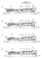
図9A〜図9Dは、係止状態から係止解除状態に移行する様子の説明図である。
・ Connection stage 5 (Release of locked state and absorption of dimensional tolerance by Z-floating)
FIG. 9A to FIG. 9D are explanatory views showing a state of shifting from the locked state to the unlocked state.
図9Aは、図8に示す状態を示している(係合部18が被係合部24に係合した状態)。既に説明したように、図9Aに示す状態では、内部ハウジング14の係止爪部16は、外部ハウジング13の移動規制部17に係止されており、外部ハウジング13と内部ハウジング14とが係止状態(互いに移動できない状態)となっている。
FIG. 9A shows the state shown in FIG. 8 (the state where the engaging
図9Aに示す状態(係合部18が被係合部24に係合した状態)から更にねじ締め動作を継続してコネクタモジュール10同士を更に近接させると、図9Bに示すように、プラグ側ハウジング23の係止解除部25が内部ハウジング14の係止爪部16をレセプタクル側フェルール15A側(図9Aの下側)に弾性変形させ、これにより、外部ハウジング13(光レセプタクル2側)の移動規制部17による係止爪部16の係止が外れ、係止解除状態になる。これにより、外部ハウジング13と、内部ハウジング14との係止状態が解除され、内部ハウジング14は、外部ハウジング13に対して前側(プラグ側とは反対側)に移動可能になる。なお、図9Bに示す状態では、図9Aに示す状態と比べて、ばね28A及びばね28Bが圧縮変形している。
When the screw tightening operation is further continued from the state shown in FIG. 9A (the engaging
図9Bに示すように係止解除状態になると、内部ハウジング14が外部ハウジング13に対して前側(プラグ側とは反対側)に移動可能になるため、図9Cに示すように、ばね28A及びばね28Bの力によって内部ハウジング14が外部ハウジング13に対して後側(プラグ側)に移動し、再び係合部18が被係合部24に係合した状態になる。この結果、内部ハウジング14とプラグ側ハウジング23とが所定の位置関係になり、ばね28A及びばね28Bが所定量で変形した状態になるため、レセプタクル側フェルール15A及びプラグ側フェルール15Bが、ばね28A及びばね28Bによって、所定の押圧力で突き合わせられた状態になる。
In the unlocked state as shown in FIG. 9B, the
ところで、本実施形態の光コネクタ1は複数のコネクタモジュール10を備えており、各コネクタモジュール10の取り付け誤差などの影響によって、各コネクタモジュール10のZ方向の位置にズレが生じている。このようにコネクタモジュール10のZ方向の位置ずれ(寸法公差)があるため、或るコネクタモジュール10が係止状態(図9A参照)から係止解除状態(図9C参照)に移行したとしても、別のコネクタモジュール10は未だ係止解除状態に移行していないおそれがある。そこで、全てのコネクタモジュール10が係止解除状態に移行するように、図9Cに示す状態から更にねじ締め動作を継続してコネクタモジュール10同士を更に近接させる必要がある。
By the way, the optical connector 1 of this embodiment is provided with the some
図9Cに示す状態から更にコネクタモジュール10同士を更に近接させたとき、既に係止解除状態になっているため、図9Dに示すように、内部ハウジング14が外部ハウジング13に対して前側(プラグ側とは反対側)に移動することができる。このとき、係合部18が被係合部24に係合した状態であるため、内部ハウジング14に係合されたプラグ側ハウジング23も、内部ハウジング14と一体的に、外部ハウジング13に対して移動することになる。このように、内部ハウジング14とプラグ側ハウジング23が一体的に外部ハウジング13に対してZ方向(ここでは特にプラグ側とは反対側)に移動することを「Zフローティング」と呼ぶことがあり、Zフローティングを可能にする機構のことを「Zフローティング機構」と呼ぶことがある。
When the
本実施形態では、係止解除状態の後、内部ハウジング14とプラグ側ハウジング23とが一体的に外部ハウジング13に対して前側(プラグ側とは反対側)に移動するため、内部ハウジング14とプラグ側ハウジング23とが所定の位置関係になった状態が保持されている。このため、内部ハウジング14とプラグ側ハウジング23が一体的に外部ハウジング13に対してZ方向に移動した後においても、ばね28A及びばね28Bが所定量で変形した状態が保持されており、この結果、レセプタクル側フェルール15A及びプラグ側フェルール15Bが所定の押圧力で突き合わせられた状態も保持されている。
In the present embodiment, the
また、本実施形態では、コネクタモジュール10のZ方向の位置ずれ(寸法公差)があったとしても、各コネクタモジュール10において寸法公差に応じた移動量でZフローティングがそれぞれ行われることによって、寸法公差を吸収することができる。また、本実施形態によれば、寸法公差を吸収させたときに、レセプタクル側フェルール15Aやプラグ側フェルール15Bに付勢される押圧力がコネクタモジュール10ごとに異なることなく、いずれのコネクタモジュールにおいても、レセプタクル側フェルール15Aやプラグ側フェルール15Bに所定の押圧力が付勢された状態を保持することができる。
Further, in this embodiment, even if there is a displacement (dimension tolerance) in the Z direction of the
本実施形態の光コネクタ1は複数のコネクタモジュール10を備えている。このため、全てのコネクタモジュール10の内部ハウジング14とプラグ側ハウジング23とが所定の位置関係(係合部18が被係合部24に係合した状態)になるためには、各コネクタモジュール10に設けられたばね28A及びばね28Bを全て所定量変形させる必要がある。この複数のコネクタモジュール10の全てのばね(ばね28A及びばね28B)を所定量変形させるためには、大きな力を必要とするため、作業者の手で直接的に押し付けて作用させることは困難である。
The optical connector 1 according to the present embodiment includes a plurality of
本実施形態の光コネクタ1は、レセプタクル側円筒部6とナット部19のねじ締め動作によりレセプタクル側コネクタモジュール11とプラグ側コネクタモジュール12とを互いに近づくように移動させている。このねじの締め付けトルクにより、大きな軸力(レセプタクル側コネクタモジュール11とプラグ側コネクタモジュール12とが互いに近づく力)を発生させている。このため、作業者はねじ締め動作をするだけで、複数のコネクタモジュール10の全てのばね(ばね28A及びばね28B)を所定量変形させる力を発生させることができる。
In the optical connector 1 of this embodiment, the receptacle-
さらに、本実施形態では、コネクタモジュール10のZ方向の位置ずれ(寸法公差)があったとしても、各コネクタモジュール10において寸法公差に応じた移動量でZフローティングがそれぞれ行われる。このため、或るコネクタモジュール10が係止状態(図9A参照)から係止解除状態(図9C参照)に移行したときに、未だ係止解除状態に移行していない別のコネクタモジュール10同士を更に近接させるために、係止解除状態となったコネクタモジュール10のばね28A及びばね28Bによる押圧力はこれ以上増加しない(所定の押圧力が維持されている)。これにより、Zフローティングがそれぞれ行われない光コネクタと比べて、作業者はより少ない力で高密度多心光ファイバ同士を接続する複数のフェルールを一括接続することができる。
Furthermore, in this embodiment, even if there is a position shift (dimension tolerance) in the Z direction of the
<光レセプタクル2と光プラグ3との抜去時の様子>
次に、光レセプタクル2と光プラグ3との抜去シーケンスについて説明する。光レセプタクル2と光プラグ3との抜去は、上述の光レセプタクル2と光プラグ3との接続シーケンスの逆の順序で行われる。
<State when
Next, a removal sequence of the
光レセプタクル2と光プラグ3の抜去シーケンスは、レセプタクル側円筒部6とナット部19との螺合を緩めるという一つの動作のみで行うことができる。以下、このレセプタクル側円筒部6とナット部19との螺合を緩める動作のことを、「ねじ緩め動作」と呼ぶことがある。このねじ緩め動作により、レセプタクル側コネクタモジュール11とプラグ側コネクタモジュール12とは互いに離れるように移動し、接続が解除される。これにより、光レセプタクル2と光プラグ3の接続の解除を行う作業者は、ねじ緩め動作という簡易な作業を行うだけで、容易に高密度多心光ファイバ同士を接続する複数のフェルールを一括に接続を解除することができる。
The removal sequence of the
・抜去段階1の前(ねじ緩め動作開始前)
抜去段階1の前、すなわちレセプタクル側円筒部6とナット部19との螺合を緩める前は、外部ハウジング13(光レセプタクル2側)の移動規制部17による係止爪部16の係止が外れ、係止解除状態となっている。このため、内部ハウジング14は、外部ハウジング13に対してZ方向に移動可能になっている。
・ Before extraction stage 1 (before starting screw loosening operation)
Before the extraction stage 1, that is, before loosening the screw connection between the receptacle-side
・抜去段階1(外部ハウジング13と内部ハウジング14との係止)
抜去段階1では、プラグ側ハウジング23(光プラグ3側)の係止解除部25が、内部ハウジング14の係止爪部16をレセプタクル側フェルール15A側(図9Aの下側)に弾性変形させた状態から外れる。つまり、係止爪部16は外部ハウジング13(光レセプタクル2側)の移動規制部17により再び係止される。外部ハウジング13と、内部ハウジング14とは再び係止状態となり、内部ハウジング14は、外部ハウジング13に対して、前側(プラグ側とは反対側)に移動することが規制されている。また、内部ハウジング14の規制突起33が外部ハウジング13に当接することにより、内部ハウジング14が外部ハウジング13に対して後側(プラグ側)に抜けてしまうことが防止されている。
Extraction stage 1 (engagement between the
In the extraction stage 1, the locking
・抜去段階2(フェルール端面同士の機械的基準面の固定解除)
抜去段階2では、内部ハウジング14の係合部18が、プラグ側ハウジング23の被係合部24との係合状態から外れ、所定の位置関係に保持されていた内部ハウジング14とプラグ側ハウジング23が離間し、レセプタクル側フェルール15Aとプラグ側フェルール15Bとの端面同士の突き当たり面(機械的基準面)の固定が解除される。このとき、プラグ側ハウジング23の被係合部24にある後方当接面31(図7参照)が、係合部18に当接することで、係合を解除するためのガイドとなっている。また、所定量で変形していたばね28A及びばね28Bは、内部ハウジング14とプラグ側ハウジング23との離間に伴って、徐々に元の長さに戻る。
・ Extraction stage 2 (unfixing of the mechanical reference surface between ferrule end faces)
In the
・抜去段階3(フェルール端面同士の位置合わせ)
接続段階3で、レセプタクル側フェルール15Aと、プラグ側フェルール15Bとの端面同士の突き当たりが外れる。さらに、フェルールピン26とフェルール孔27との嵌合が解かれる。
-Extraction stage 3 (positioning of ferrule end faces)
At the
・抜去段階4及び抜去段階5
接続段階4で、プラグ側ハウジング23とレセプタクル側ハウジングとの接触が外れる。そして、接続段階5で、レセプタクル側円筒部6とナット部19との螺合が外れる。これにより、光レセプタクル2と光プラグ3の抜去シーケンスが完了する。
-Extraction stage 4 and
In the connection stage 4, the contact between the plug-
===その他の実施形態===
上記の実施形態では、2000心の光ファイバを接続する際の高密度多心光コネクタを示したが、例えば、1000心の光ファイバを接続する際の高密度多心光コネクタであってもよい。
=== Other Embodiments ===
In the above embodiment, a high-density multi-core optical connector for connecting 2000 optical fibers is shown. However, for example, a high-density multi-core optical connector for connecting 1000 optical fibers may be used. .
図10Aは、光レセプタクル35のレセプタクル側コネクタモジュール37部分を拡大した斜視図である。図10Bは、光プラグ36のプラグ側コネクタモジュール38部分を拡大した斜視図である。図10Aに示すレセプタクル側コネクタモジュール37は、1000心の光ファイバを接続する光コネクタ34のレセプタクル側のコネクタモジュールである。レセプタクル側コネクタモジュール37は、左右方向に3個、上下方向に2個、計6個配列されている。図10Bに示すプラグ側コネクタモジュール38は、1000心の光ファイバを接続する光コネクタ34のプラグ側のコネクタモジュールである。プラグ側コネクタモジュール38は、左右方向に3個、上下方向に2個、計6個配列されている。
FIG. 10A is an enlarged perspective view of the receptacle-
光コネクタ34は、光コネクタ1に対して、レセプタクル側コネクタモジュール37及びプラグ側コネクタモジュール38の配列の個数が異なるのみで、配列の方向や、コネクタモジュール以外の他の構成は光コネクタ1と同一である。
The optical connector 34 differs from the optical connector 1 only in the number of arrangements of the receptacle-
上述した2000心の光ファイバを接続する光コネクタ1や、1000心の光ファイバを接続する光コネクタ34において、コネクタモジュールの配列の仕方が他のものであってもよい。例えば、コネクタ1において、左右方向に3個、上下方向に4個配列されているものや、放射状に12個配列されているものであってもよい。 In the optical connector 1 for connecting the 2000 optical fibers described above and the optical connector 34 for connecting the 1000 optical fibers, the connector modules may be arranged in other ways. For example, in the connector 1, three connectors may be arranged in the left-right direction and four in the up-down direction, or twelve may be arranged radially.
上記の実施形態では、光レセプタクル2は外周にねじ部の形成されたレセプタクル側円筒部6を備え、光プラグ3はナット部19を備えており、光レセプタクル2と光プラグ3とを螺合させていた。但し、光レセプタクル2や光プラグ3がねじ部を備えていなくてもよい。例えば、ねじ部を形成する代わりに、BNCコネクタで採用されているバヨネット機構が形成されていても良い。
In the above-described embodiment, the
上記の実施形態では、光レセプタクル2がXYフローティング機構を備えているが、光レセプタクル2がXYフローティング機構を備えていなくてもよい。
In the above embodiment, the
上記の実施形態は、本発明の理解を容易にするためのものであり、本発明を限定して解釈するためのものではない。本発明は、その趣旨を逸脱することなく、変更・改良され得ると共に、本発明には、その等価物が含まれることは言うまでもない。 The above-described embodiments are for facilitating the understanding of the present invention, and are not intended to limit the present invention. The present invention can be modified and improved without departing from the gist thereof, and it goes without saying that the present invention includes equivalents thereof.
1 光コネクタ、2 光レセプタクル、3 光プラグ、
4A・4B 光ファイバ保持部、5 把持部、6 レセプタクル側円筒部、
7A・7B 平坦部、8 レセプタクル側凹部、9 レセプタクル側凸部、
10 コネクタモジュール、11 レセプタクル側コネクタモジュール、
12 プラグ側コネクタモジュール、13 外部ハウジング、14 内部ハウジング、
15A レセプタクル側フェルール、15B プラグ側フェルール、
16 係止爪部、17 移動規制部、18 係合部、
19 ナット部、20 プラグ側円筒部、21 プラグ側凸部、
22 プラグ側凹部、23 プラグ側ハウジング、24 被係合部、
25 係止解除部、26 フェルールピン、27 フェルール孔、
28A・28B ばね部、29 係合ガイド部、
30 前方当接面、31 後方当接面、32 凸状部、33 規制突起、
34 光コネクタ、35 光レセプタクル、36 光プラグ、
37 レセプタクル側コネクタモジュール、38 プラグ側コネクタモジュール
1 optical connector, 2 optical receptacles, 3 optical plugs,
4A / 4B optical fiber holding part, 5 gripping part, 6 receptacle side cylindrical part,
7A, 7B Flat part, 8 Receptacle side concave part, 9 Receptacle side convex part,
10 connector module, 11 receptacle side connector module,
12 Plug side connector module, 13 External housing, 14 Internal housing,
15A receptacle ferrule, 15B plug ferrule,
16 locking claw part, 17 movement restricting part, 18 engaging part,
19 Nut part, 20 Plug side cylindrical part, 21 Plug side convex part,
22 plug-side recess, 23 plug-side housing, 24 engaged portion,
25 Unlocking part, 26 Ferrule pin, 27 Ferrule hole,
28A / 28B Spring part, 29 Engagement guide part,
30 front abutting surface, 31 rear abutting surface, 32 convex portion, 33 regulating protrusion,
34 optical connector, 35 optical receptacle, 36 optical plug,
37 Receptacle side connector module, 38 Plug side connector module
Claims (8)
前記光レセプタクルは、外部ハウジングと、内部ハウジングと、前記内部ハウジングに収容されたレセプタクル側フェルールと、前記レセプタクル側フェルールに押圧力を付与するレセプタクル側バネと、を有するレセプタクル側コネクタモジュールを複数備え、
前記光プラグは、プラグ側ハウジングと、前記プラグ側ハウジングに収容されたプラグ側フェルールと、前記プラグ側フェルールに押圧力を付与するプラグ側バネと、を有するプラグ側コネクタモジュールを複数備え、
前記内部ハウジングは係合部を有し、前記プラグ側ハウジングは被係合部を有し、前記係合部と前記被係合部とが係合した状態では、前記内部ハウジングと前記プラグ側ハウジングとが所定の位置関係になり、前記レセプタクル側バネと前記プラグ側バネとによって前記レセプタクル側フェルールと前記プラグ側フェルールとが所定の押圧力で突き合わされた状態になり、
前記プラグ側ハウジングは係止解除部を有し、前記係止解除部が、前記内部ハウジングが前記外部ハウジングに係止された係止状態から係止解除状態にすると、前記内部ハウジングが前記外部ハウジングに対して移動可能になり、
前記光レセプタクルは、外周にネジ部が形成されたレセプタクル側円筒部を備え、前記光プラグは、前記レセプタクル側円筒部に螺合するナット部を備え、前記光レセプタクルと前記光プラグとを接続する際に、前記レセプタクル側円筒部と前記ナット部との螺合を進めることにより、それぞれの前記レセプタクル側コネクタモジュール及び前記プラグ側コネクタモジュールにおいて、前記係止状態から前記係止解除状態になった後、前記係合部と前記被係合部とが係合した状態で、前記内部ハウジングと前記プラグ側ハウジングとが前記外部ハウジングに対して着脱方向に移動する
ことを特徴とする光コネクタ。 An optical connector having a detachable optical receptacle and an optical plug,
The optical receptacle includes a plurality of receptacle-side connector modules having an outer housing, an inner housing, a receptacle-side ferrule accommodated in the inner housing, and a receptacle-side spring that applies a pressing force to the receptacle-side ferrule,
The optical plug includes a plurality of plug-side connector modules including a plug-side housing, a plug-side ferrule housed in the plug-side housing, and a plug-side spring that applies a pressing force to the plug-side ferrule,
The inner housing has an engaging portion, the plug-side housing has an engaged portion, and the inner housing and the plug-side housing are in a state where the engaging portion and the engaged portion are engaged. Are in a predetermined positional relationship, the receptacle-side spring and the plug-side spring are in a state where the receptacle-side ferrule and the plug-side ferrule are abutted with a predetermined pressing force,
The plug-side housing has an unlocking portion, and when the unlocking portion changes from the locked state in which the inner housing is locked to the outer housing to the unlocked state, the inner housing is moved to the outer housing. Can be moved against
The optical receptacle includes a receptacle-side cylindrical portion having a thread portion formed on an outer periphery thereof, and the optical plug includes a nut portion that is screwed to the receptacle-side cylindrical portion, and connects the optical receptacle and the optical plug. when, by advancing the screwing between the receptacle-side cylinder portion and the nut portion, in each of the receptacle connector module and the plug-side connector module, after becoming the unlocking state from the latched state The optical connector is characterized in that the inner housing and the plug-side housing move in the attaching / detaching direction with respect to the outer housing in a state where the engaging portion and the engaged portion are engaged.
ことを特徴とする請求項1に記載の光コネクタ。 The optical connector according to claim 1 , wherein when the receptacle-side cylindrical portion and the nut portion are not screwed together, the locked state is not changed to the locked state .
ことを特徴とする請求項2に記載の光コネクタ。 The optical connector according to claim 2, wherein the optical plug includes a plug-side cylindrical portion that fits inside the receptacle-side cylindrical portion.
ことを特徴とする請求項3に記載の光コネクタ。The optical connector according to claim 3.
ことを特徴とする請求項1から4のいずれかに記載の光コネクタ。 The optical connector in the unlocked state engages the engaging portion and the engaged portion after the locked state is obtained by loosening the threaded engagement between the receptacle-side cylindrical portion and the nut portion. the optical connector according to any one of claims 1 to 4 which combined state, characterized in that it is released.
ことを特徴とする請求項1から5のいずれかに記載の光コネクタ。 The said optical receptacle is provided with the housing | casing which hold | maintains the said external housing, The said external housing is provided so that the movement to the direction perpendicular | vertical to the attachment / detachment direction with respect to the said housing | casing is possible. The optical connector according to any one of 5 .
ことを特徴とする請求項1から6のいずれかに記載の光コネクタ。 Wherein the receptacle ferrule and the plug-side ferrule, an optical connector according to any one of claims 1 to 6, characterized in that the lens is a coupling type ferrule.
前記光レセプタクルは、外部ハウジングと、内部ハウジングと、前記内部ハウジングに収容されたレセプタクル側フェルールと、前記レセプタクル側フェルールに押圧力を付与するレセプタクル側バネと、を有するレセプタクル側コネクタモジュールを複数備え、
前記光プラグは、プラグ側ハウジングと、前記プラグ側ハウジングに収容されたプラグ側フェルールと、前記プラグ側フェルールに押圧力を付与するプラグ側バネと、を有するプラグ側コネクタモジュールを複数備え、
前記内部ハウジングは係合部を有し、前記プラグ側ハウジングは被係合部を有し、前記係合部と前記被係合部とが係合した状態では、前記内部ハウジングと前記プラグ側ハウジングとが所定の位置関係になり、前記レセプタクル側バネと前記プラグ側バネとによって前記レセプタクル側フェルールと前記プラグ側フェルールとが所定の押圧力で突き合わされた状態になり、
前記プラグ側ハウジングは係止解除部を有し、前記係止解除部が、前記内部ハウジングが前記外部ハウジングに係止された係止状態から係止解除状態にすると、前記内部ハウジングが前記外部ハウジングに対して移動可能になり、
前記光レセプタクルは、外周にネジ部が形成されたレセプタクル側円筒部を備え、前記光プラグは、前記レセプタクル側円筒部に螺合するナット部を備え、前記光レセプタクルと前記光プラグとを接続する際に、前記レセプタクル側円筒部と前記ナット部との螺合を進めることにより、それぞれの前記レセプタクル側コネクタモジュール及び前記プラグ側コネクタモジュールにおいて、前記係止状態から前記係止解除状態になった後、前記係合部と前記被係合部とが係合した状態で、前記内部ハウジングと前記プラグ側ハウジングとが前記外部ハウジングに対して着脱方向に移動する
ことを特徴とする光コネクタの接続方法。 A method of connecting an optical connector having a detachable optical receptacle and an optical plug,
The optical receptacle includes a plurality of receptacle-side connector modules having an outer housing, an inner housing, a receptacle-side ferrule accommodated in the inner housing, and a receptacle-side spring that applies a pressing force to the receptacle-side ferrule,
The optical plug includes a plurality of plug-side connector modules including a plug-side housing, a plug-side ferrule housed in the plug-side housing, and a plug-side spring that applies a pressing force to the plug-side ferrule,
The inner housing has an engaging portion, the plug-side housing has an engaged portion, and the inner housing and the plug-side housing are in a state where the engaging portion and the engaged portion are engaged. Are in a predetermined positional relationship, the receptacle-side spring and the plug-side spring are in a state where the receptacle-side ferrule and the plug-side ferrule are abutted with a predetermined pressing force,
The plug-side housing has an unlocking portion, and when the unlocking portion changes from the locked state in which the inner housing is locked to the outer housing to the unlocked state, the inner housing is moved to the outer housing. Can be moved against
The optical receptacle includes a receptacle-side cylindrical portion having a thread portion formed on an outer periphery thereof, and the optical plug includes a nut portion that is screwed to the receptacle-side cylindrical portion, and connects the optical receptacle and the optical plug. when, by advancing the screwing between the receptacle-side cylinder portion and the nut portion, in each of the receptacle connector module and the plug-side connector module, after becoming the unlocking state from the latched state The method of connecting an optical connector, wherein the inner housing and the plug-side housing move in a detachable direction with respect to the outer housing in a state where the engaging portion and the engaged portion are engaged. .
Priority Applications (1)
| Application Number | Priority Date | Filing Date | Title |
|---|---|---|---|
| JP2016171770A JP6421149B2 (en) | 2016-09-02 | 2016-09-02 | Optical connector and optical connector connection method |
Applications Claiming Priority (1)
| Application Number | Priority Date | Filing Date | Title |
|---|---|---|---|
| JP2016171770A JP6421149B2 (en) | 2016-09-02 | 2016-09-02 | Optical connector and optical connector connection method |
Publications (2)
| Publication Number | Publication Date |
|---|---|
| JP2018036589A JP2018036589A (en) | 2018-03-08 |
| JP6421149B2 true JP6421149B2 (en) | 2018-11-07 |
Family
ID=61565745
Family Applications (1)
| Application Number | Title | Priority Date | Filing Date |
|---|---|---|---|
| JP2016171770A Active JP6421149B2 (en) | 2016-09-02 | 2016-09-02 | Optical connector and optical connector connection method |
Country Status (1)
| Country | Link |
|---|---|
| JP (1) | JP6421149B2 (en) |
Families Citing this family (2)
| Publication number | Priority date | Publication date | Assignee | Title |
|---|---|---|---|---|
| JP6546978B2 (en) | 2017-11-29 | 2019-07-17 | 株式会社フジクラ | Optical connector and method of connecting optical connector |
| JP6535396B1 (en) * | 2018-02-16 | 2019-06-26 | 株式会社フジクラ | Optical connector and method of connecting optical connector |
Family Cites Families (6)
| Publication number | Priority date | Publication date | Assignee | Title |
|---|---|---|---|---|
| US4279469A (en) * | 1975-05-27 | 1981-07-21 | The United States Of America As Represented By The Secretary Of The Navy | Separable fiber optic cable connector |
| JP2771870B2 (en) * | 1989-12-01 | 1998-07-02 | 日本電信電話株式会社 | Optical connector |
| JPH0521211U (en) * | 1991-08-29 | 1993-03-19 | ヒロセ電機株式会社 | Optical connector structure |
| JP3349405B2 (en) * | 1997-08-07 | 2002-11-25 | 古河電気工業株式会社 | Batch connection structure of multiple optical connectors |
| US20060045428A1 (en) * | 2004-08-24 | 2006-03-02 | Thomas Theuerkorn | Fiber optic receptacle and plug assemblies |
| JP6318008B2 (en) * | 2014-05-30 | 2018-04-25 | 株式会社フジクラ | Optical connector |
-
2016
- 2016-09-02 JP JP2016171770A patent/JP6421149B2/en active Active
Also Published As
| Publication number | Publication date |
|---|---|
| JP2018036589A (en) | 2018-03-08 |
Similar Documents
| Publication | Publication Date | Title |
|---|---|---|
| JP6318008B2 (en) | Optical connector | |
| JP5439319B2 (en) | Optical connector and optical connector insertion / extraction method | |
| US20120027359A1 (en) | Optical connector and connector connection system | |
| JP4800136B2 (en) | Optical receptacle housing, optical connector receptacle and optical device | |
| CN111226150B (en) | Optical connector and method of connecting optical connector | |
| TW201624034A (en) | Plug with built-in connector | |
| US9140862B2 (en) | Methods, apparatuses and systems for blind mating multi-optical fiber connector modules | |
| WO2019106870A1 (en) | Optical connector and method for connecting optical connector | |
| JP6421149B2 (en) | Optical connector and optical connector connection method | |
| JP4087046B2 (en) | Optical cable adapter or connector and its mounting member | |
| JP6588754B2 (en) | Optical connector cleaning tool and attachment | |
| EP1182477A1 (en) | Optical connector housing, optical connector using the optical connector housing and connection structure between optical connector and optical component using the optical connector housing | |
| US10036862B2 (en) | Connector | |
| JP7036772B2 (en) | Optical connector | |
| JP2014112218A (en) | Optical connector | |
| JP2018036590A (en) | Optical connector | |
| WO2019159431A1 (en) | Optical connector and method for connecting optical connector | |
| JP2012032656A (en) | Optical connector and connector connection system | |
| JP5685336B1 (en) | Attachment attached to optical connector and cleaning method of optical connector | |
| WO2022259345A1 (en) | Optical connector | |
| JP2015203796A (en) | optical connector | |
| WO2022107366A1 (en) | Cap | |
| JP2011027758A (en) | Optical connector | |
| US20230324625A1 (en) | Multi-fiber reusable splicing systems |
Legal Events
| Date | Code | Title | Description |
|---|---|---|---|
| A977 | Report on retrieval |
Free format text: JAPANESE INTERMEDIATE CODE: A971007 Effective date: 20180319 |
|
| A131 | Notification of reasons for refusal |
Free format text: JAPANESE INTERMEDIATE CODE: A131 Effective date: 20180327 |
|
| A521 | Request for written amendment filed |
Free format text: JAPANESE INTERMEDIATE CODE: A523 Effective date: 20180523 |
|
| TRDD | Decision of grant or rejection written | ||
| A01 | Written decision to grant a patent or to grant a registration (utility model) |
Free format text: JAPANESE INTERMEDIATE CODE: A01 Effective date: 20180918 |
|
| A61 | First payment of annual fees (during grant procedure) |
Free format text: JAPANESE INTERMEDIATE CODE: A61 Effective date: 20181015 |
|
| R150 | Certificate of patent or registration of utility model |
Ref document number: 6421149 Country of ref document: JP Free format text: JAPANESE INTERMEDIATE CODE: R150 |
|
| R250 | Receipt of annual fees |
Free format text: JAPANESE INTERMEDIATE CODE: R250 |
|
| R250 | Receipt of annual fees |
Free format text: JAPANESE INTERMEDIATE CODE: R250 |
|
| R250 | Receipt of annual fees |
Free format text: JAPANESE INTERMEDIATE CODE: R250 |