JP6416660B2 - Inkjet recording apparatus and inkjet recording method - Google Patents
Inkjet recording apparatus and inkjet recording method Download PDFInfo
- Publication number
- JP6416660B2 JP6416660B2 JP2015040773A JP2015040773A JP6416660B2 JP 6416660 B2 JP6416660 B2 JP 6416660B2 JP 2015040773 A JP2015040773 A JP 2015040773A JP 2015040773 A JP2015040773 A JP 2015040773A JP 6416660 B2 JP6416660 B2 JP 6416660B2
- Authority
- JP
- Japan
- Prior art keywords
- recording heads
- recording
- post
- droplets
- pair
- Prior art date
- Legal status (The legal status is an assumption and is not a legal conclusion. Google has not performed a legal analysis and makes no representation as to the accuracy of the status listed.)
- Active
Links
Images


Classifications
-
- B—PERFORMING OPERATIONS; TRANSPORTING
- B41—PRINTING; LINING MACHINES; TYPEWRITERS; STAMPS
- B41J—TYPEWRITERS; SELECTIVE PRINTING MECHANISMS, i.e. MECHANISMS PRINTING OTHERWISE THAN FROM A FORME; CORRECTION OF TYPOGRAPHICAL ERRORS
- B41J2/00—Typewriters or selective printing mechanisms characterised by the printing or marking process for which they are designed
- B41J2/005—Typewriters or selective printing mechanisms characterised by the printing or marking process for which they are designed characterised by bringing liquid or particles selectively into contact with a printing material
- B41J2/01—Ink jet
- B41J2/21—Ink jet for multi-colour printing
- B41J2/2107—Ink jet for multi-colour printing characterised by the ink properties
- B41J2/2114—Ejecting transparent or white coloured liquids, e.g. processing liquids
-
- B—PERFORMING OPERATIONS; TRANSPORTING
- B41—PRINTING; LINING MACHINES; TYPEWRITERS; STAMPS
- B41J—TYPEWRITERS; SELECTIVE PRINTING MECHANISMS, i.e. MECHANISMS PRINTING OTHERWISE THAN FROM A FORME; CORRECTION OF TYPOGRAPHICAL ERRORS
- B41J19/00—Character- or line-spacing mechanisms
- B41J19/14—Character- or line-spacing mechanisms with means for effecting line or character spacing in either direction
- B41J19/142—Character- or line-spacing mechanisms with means for effecting line or character spacing in either direction with a reciprocating print head printing in both directions across the paper width
-
- B—PERFORMING OPERATIONS; TRANSPORTING
- B41—PRINTING; LINING MACHINES; TYPEWRITERS; STAMPS
- B41J—TYPEWRITERS; SELECTIVE PRINTING MECHANISMS, i.e. MECHANISMS PRINTING OTHERWISE THAN FROM A FORME; CORRECTION OF TYPOGRAPHICAL ERRORS
- B41J2/00—Typewriters or selective printing mechanisms characterised by the printing or marking process for which they are designed
- B41J2/005—Typewriters or selective printing mechanisms characterised by the printing or marking process for which they are designed characterised by bringing liquid or particles selectively into contact with a printing material
- B41J2/01—Ink jet
- B41J2/135—Nozzles
- B41J2/145—Arrangement thereof
- B41J2/15—Arrangement thereof for serial printing
-
- B—PERFORMING OPERATIONS; TRANSPORTING
- B41—PRINTING; LINING MACHINES; TYPEWRITERS; STAMPS
- B41J—TYPEWRITERS; SELECTIVE PRINTING MECHANISMS, i.e. MECHANISMS PRINTING OTHERWISE THAN FROM A FORME; CORRECTION OF TYPOGRAPHICAL ERRORS
- B41J2/00—Typewriters or selective printing mechanisms characterised by the printing or marking process for which they are designed
- B41J2/005—Typewriters or selective printing mechanisms characterised by the printing or marking process for which they are designed characterised by bringing liquid or particles selectively into contact with a printing material
- B41J2/01—Ink jet
- B41J2/21—Ink jet for multi-colour printing
- B41J2/2107—Ink jet for multi-colour printing characterised by the ink properties
- B41J2/2114—Ejecting transparent or white coloured liquids, e.g. processing liquids
- B41J2/2117—Ejecting white liquids
-
- B—PERFORMING OPERATIONS; TRANSPORTING
- B41—PRINTING; LINING MACHINES; TYPEWRITERS; STAMPS
- B41J—TYPEWRITERS; SELECTIVE PRINTING MECHANISMS, i.e. MECHANISMS PRINTING OTHERWISE THAN FROM A FORME; CORRECTION OF TYPOGRAPHICAL ERRORS
- B41J25/00—Actions or mechanisms not otherwise provided for
- B41J25/001—Mechanisms for bodily moving print heads or carriages parallel to the paper surface
- B41J25/006—Mechanisms for bodily moving print heads or carriages parallel to the paper surface for oscillating, e.g. page-width print heads provided with counter-balancing means or shock absorbers
-
- B—PERFORMING OPERATIONS; TRANSPORTING
- B41—PRINTING; LINING MACHINES; TYPEWRITERS; STAMPS
- B41J—TYPEWRITERS; SELECTIVE PRINTING MECHANISMS, i.e. MECHANISMS PRINTING OTHERWISE THAN FROM A FORME; CORRECTION OF TYPOGRAPHICAL ERRORS
- B41J11/00—Devices or arrangements of selective printing mechanisms, e.g. ink-jet printers or thermal printers, for supporting or handling copy material in sheet or web form
- B41J11/0015—Devices or arrangements of selective printing mechanisms, e.g. ink-jet printers or thermal printers, for supporting or handling copy material in sheet or web form for treating before, during or after printing or for uniform coating or laminating the copy material before or after printing
- B41J11/002—Curing or drying the ink on the copy materials, e.g. by heating or irradiating
- B41J11/0021—Curing or drying the ink on the copy materials, e.g. by heating or irradiating using irradiation
- B41J11/00214—Curing or drying the ink on the copy materials, e.g. by heating or irradiating using irradiation using UV radiation
Description
本発明は、インクの液滴を吐出することで記録媒体の上に画像を形成するインクジェット記録装置及びインクジェット記録方法に関する。 The present invention relates to an ink jet recording apparatus and an ink jet recording method for forming an image on a recording medium by discharging ink droplets.
従来から、商業印刷分野において、インクの液滴を記録媒体に向けて吐出し、該液滴に対してエネルギーを付与する後処理を施すことで、記録媒体の上に画像を定着・形成するインクジェット記録技術が開発されている。例えば、紫外線硬化インクを吐出可能な複数の記録ヘッドを保持する矩形状のヘッドホルダと、該ヘッドホルダの両端に配置された一対の紫外光源ユニットを備える装置構成が知られている(特許文献1を参照)。 Conventionally, in a commercial printing field, an ink jet that fixes and forms an image on a recording medium by ejecting ink droplets toward a recording medium and applying post-processing that imparts energy to the droplets. Recording technology has been developed. For example, there is known an apparatus configuration including a rectangular head holder that holds a plurality of recording heads capable of discharging ultraviolet curable ink, and a pair of ultraviolet light source units disposed at both ends of the head holder (Patent Document 1). See).
ところで、いわゆるマルチパス(又はシャトルパス)記録方式に関して、高速での印刷処理を可能にすべく、往路走査及び復路走査のタイミングにて記録ヘッドから液滴を吐出することで画像を完成させる「双方向記録モード」がある。この記録モードを採用するとき、往路走査で得られる画像と、復路走査で得られる画像の間に画質の差異(不均質)が生じることがある。 By the way, regarding the so-called multi-pass (or shuttle pass) recording method, in order to enable high-speed printing processing, an image is completed by ejecting liquid droplets from the recording head at the timing of forward scanning and backward scanning. "Directional recording mode". When this recording mode is employed, a difference in image quality (inhomogeneity) may occur between an image obtained by forward scanning and an image obtained by backward scanning.
そこで、特許文献2では、複数の記録ヘッドを階段状に配置すると共に、特定波長の紫外線を通過するフィルタを当該配置状態に対応して階段状に形成する装置が提案されている。これにより、往路時及び復路時に着弾したインクに対して同一のタイミングで紫外線を照射可能となり、画質ムラが抑制される旨が記載されている。
Therefore,
しかしながら、特許文献2にて提案された装置では、記録ヘッドの配置や個数を変更する都度に、少なくともフィルタの形状を変更する必要がある。特に、1回の走査にて得られる印刷領域を拡大させるべく複数の記録ヘッドのスタガ配置を行う場合、フィルタの形状のみならず、紫外光源の配置を更に考慮する必要があり得る。つまり、複数の記録ヘッドの位置関係において後処理ユニットの設計が複雑になるという問題があった。
However, in the apparatus proposed in
本発明は、上述した課題に鑑みてなされたものであり、後処理に起因する画像全体の不均質を抑制しつつも、後処理ユニットの形状及び配置を容易に設計可能なインクジェット記録装置及びインクジェット記録方法を提供することを目的とする。 The present invention has been made in view of the above-described problems, and an inkjet recording apparatus and an inkjet that can easily design the shape and arrangement of a post-processing unit while suppressing inhomogeneity of the entire image due to post-processing. An object is to provide a recording method.
本発明に係るインクジェット記録装置は、インクの液滴を吐出する少なくとも1つのノズル列をそれぞれ有する複数の記録ヘッドと、前記複数の記録ヘッドから記録媒体に向けて吐出された前記液滴にエネルギーを付与することで、前記インクによって形成された各ドットに対して後処理を実行する一対の後処理ユニットと、前記複数の記録ヘッドを第1方向に沿って往復移動させながら、往路走査及び復路走査のタイミングにて前記液滴を吐出することで、前記各ドットにより前記記録媒体上に画像を形成させる制御部とを備え、前記複数の記録ヘッドは、前記第1方向及び該第1方向に交差する第2方向においてそれぞれ2つ以上配置されたスタガ配置を構成し、前記一対の後処理ユニットは、前記第2方向に沿って互いに平行に、且つ、前記複数の記録ヘッドを挟んで配置され、前記一対の後処理ユニットがそれぞれ有する前記第2方向の長さは、前記複数の記録ヘッドが1回の走査にて吐出可能である前記第2方向の範囲以上であり、同色の前記液滴を吐出する2つ以上の前記ノズル列が前記一対の後処理ユニット間の中心線に対して対称となるように、前記複数の記録ヘッドが配置される。 An inkjet recording apparatus according to the present invention includes a plurality of recording heads each having at least one nozzle array that ejects ink droplets, and energy applied to the droplets ejected from the plurality of recording heads toward a recording medium. By applying, a pair of post-processing units that perform post-processing on each dot formed by the ink, and forward scanning and backward scanning while the plurality of recording heads reciprocate along the first direction. And a controller that forms an image on the recording medium by each dot by ejecting the droplets at the timing of the plurality of recording heads, wherein the plurality of recording heads intersect the first direction and the first direction. Two or more staggered arrangements are arranged in the second direction, and the pair of post-processing units are parallel to each other along the second direction, and The lengths in the second direction that are disposed between the plurality of recording heads and that each of the pair of post-processing units has in the second direction are such that the plurality of recording heads can discharge in one scan. The plurality of recording heads are arranged such that two or more nozzle rows that discharge the droplets of the same color that are equal to or greater than the range are symmetrical with respect to the center line between the pair of post-processing units.
このように、同色の液滴を吐出する2つ以上のノズル列は、一対の後処理ユニット間の中心線に対して対称に配置されるので、中心線の一方側にあるノズル列と中心線の他方側にある後処理ユニットの間の距離は、他方側にあるノズル列と一方側にある後処理ユニットの間の距離に等しくなる。これに加えて、中心線の一方側にそれぞれあるノズル列と後処理ユニットの間の距離は、他方側にそれぞれあるノズル列と後処理ユニットの間の距離に等しくなる。つまり、往路走査及び復路走査にかかわらず、液滴の着弾時点から後処理の開始時点までの待ち時間が略一定になる。 As described above, since the two or more nozzle rows that discharge droplets of the same color are arranged symmetrically with respect to the center line between the pair of post-processing units, the nozzle row and the center line on one side of the center line are arranged. The distance between the post-processing units on the other side of the nozzle is equal to the distance between the nozzle row on the other side and the post-processing unit on the one side. In addition, the distance between the nozzle row located on one side of the center line and the post-processing unit is equal to the distance between the nozzle row located on the other side and the post-processing unit. That is, the waiting time from the droplet landing time to the post-processing start time becomes substantially constant regardless of the forward scanning and the backward scanning.
また、複数の記録ヘッドのうち2つ以上のスタガ配置によってノズル列同士の配置対称性を担保するので、記録ヘッドの配置や個数が変更された場合であっても、一対の後処理ユニットの設計上の干渉がないか軽微である。これにより、後処理に起因する画像全体の不均質を抑制しつつも、後処理ユニットの形状及び配置を容易に設計できる。 In addition, since the arrangement symmetry of the nozzle rows is ensured by the arrangement of two or more staggers among a plurality of recording heads, a pair of post-processing units can be designed even when the arrangement and number of recording heads are changed. There is little or no interference above. Thereby, the shape and arrangement of the post-processing unit can be easily designed while suppressing the inhomogeneity of the entire image due to the post-processing.
また、前記複数の記録ヘッドには、異なる色の前記液滴を吐出する2つ以上の前記ノズル列が互いに平行に配置された記録ヘッドのペアが少なくとも1組含まれ、前記液滴の色毎に、2つ以上の前記ノズル列が前記中心線に対して対称となるように、前記記録ヘッドのペアが配置されることが好ましい。複数の色が混在する場合であっても、同じ色同士において、液滴の着弾時点から後処理の開始時点までの待ち時間が略一定になる。 The plurality of recording heads include at least one pair of recording heads in which two or more nozzle arrays that discharge the droplets of different colors are arranged in parallel to each other. In addition, it is preferable that the pair of recording heads be arranged so that two or more nozzle rows are symmetrical with respect to the center line. Even when a plurality of colors coexist, the waiting time from the droplet landing time to the post-processing start time is substantially constant for the same colors.
また、前記複数の記録ヘッドには、前記記録ヘッドのペアが複数組含まれ、前記搬送方向の下流側に配置される前記記録ヘッドのペアほど離間距離が長く、且つ、前記搬送方向の上流側に配置される前記記録ヘッドのペアほど離間距離が短いことが好ましい。記録ヘッドのペアは、離間距離が長いほど中心線から遠く、且つ、後処理ユニットに近い位置に配置されるので、後処理の開始時点までの待ち時間が短くなる。その結果、着弾後の液滴の流動量が相対的に少なくなる。そこで、離間距離が相対的に長い記録ヘッドのペアを搬送方向の下流側に配置し、画像の上層を形成する液滴の流動量を少なくすることで、鮮鋭感が高いマット調の画像が得られる。 The plurality of recording heads include a plurality of pairs of the recording heads, the pair of recording heads arranged on the downstream side in the transport direction has a longer separation distance, and the upstream side in the transport direction. It is preferable that the separation distance is shorter as the pair of the recording heads arranged at the same distance. Since the pair of recording heads is arranged at a position farther from the center line and closer to the post-processing unit as the separation distance is longer, the waiting time until the start time of the post-processing is shortened. As a result, the flow amount of the droplet after landing is relatively reduced. Therefore, a pair of recording heads with a relatively long separation distance is arranged on the downstream side in the transport direction to reduce the flow amount of droplets forming the upper layer of the image, thereby obtaining a matte image with high sharpness. It is done.
また、前記複数の記録ヘッドには、前記記録ヘッドのペアが複数組含まれ、前記搬送方向の下流側に配置される前記記録ヘッドのペアほど離間距離が短く、且つ、前記搬送方向の上流側に配置される前記記録ヘッドのペアほど離間距離が長いことが好ましい。記録ヘッドのペアは、離間距離が短いほど中心線に近く、且つ、後処理ユニットから遠い位置に配置されるので、後処理の開始時点までの待ち時間が長くなる。その結果、着弾後の液滴の流動量が相対的に多くなる。そこで、離間距離が相対的に短い記録ヘッドのペアを搬送方向の上流側に配置し、画像の上層を形成する液滴の流動量を多くすることで、粒状感が少ないグロス調の画像が得られる。 The plurality of recording heads include a plurality of pairs of the recording heads, the pair of recording heads arranged on the downstream side in the transport direction has a shorter separation distance, and the upstream side in the transport direction. It is preferable that the distance between the pair of the recording heads arranged in the above is longer. The shorter the separation distance, the closer the recording head pair is to the center line and the farther from the post-processing unit, the longer the waiting time until the start of post-processing. As a result, the flow amount of the droplet after landing relatively increases. Therefore, by arranging a pair of recording heads with a relatively short separation distance upstream in the transport direction and increasing the flow rate of the droplets that form the upper layer of the image, a glossy image with less graininess can be obtained. It is done.
また、前記記録ヘッドのペアは、前記中心線に近い位置の前記ノズル列ほど明度が低い色の前記液滴を吐出し、前記中心線から遠い位置の前記ノズル列ほど明度が高い色の前記液滴を吐出することが好ましい。中心線に近い位置のノズル列ほど後処理の開始時点までの待ち時間が短くなり、中心線から遠い位置のノズル列ほどこの待ち時間が長くなる。また、待ち時間が十分に短い場合には液滴の流動に起因するビーディングが起こり難い一方、待ち時間が長くなるにつれてビーディングが起こり易くなる傾向がある。そこで、視認性が相対的に高い低明度色の液滴を、中心線に近い位置のノズル列から吐出することで、ビーディングが引き起こす画質の低下を抑制できる。 Further, the pair of recording heads discharges the liquid droplets having a color with a lower brightness toward the nozzle row closer to the center line, and the liquid with a color having a higher brightness toward the nozzle row farther from the center line. It is preferable to eject droplets. The nozzle row closer to the center line has a shorter waiting time until the start of post-processing, and the nozzle row farther from the center line has a longer waiting time. In addition, when the waiting time is sufficiently short, beading due to the flow of droplets is difficult to occur, whereas beading tends to occur as the waiting time becomes longer. Accordingly, by ejecting low brightness color droplets with relatively high visibility from the nozzle row at a position close to the center line, it is possible to suppress deterioration in image quality caused by beading.
また、前記複数の記録ヘッドには、同色の前記液滴を吐出する2つ以上の前記ノズル列が互いに平行に配置された特定の記録ヘッドが少なくとも1つ含まれ、2つ以上の前記ノズル列が前記中心線に対して対称となるように、前記特定の記録ヘッドが配置されることが好ましい。1つの記録ヘッドのみを用いてノズル列同士の配置対称性を実現可能となり、2つ以上を用いる場合と比べて、記録ヘッドの位置・姿勢の調整作業が容易になる。 The plurality of recording heads include at least one specific recording head in which two or more nozzle arrays that discharge the droplets of the same color are arranged in parallel to each other, and the two or more nozzle arrays It is preferable that the specific recording head is arranged so that is symmetrical with respect to the center line. The arrangement symmetry of the nozzle rows can be realized using only one recording head, and the adjustment operation of the position and orientation of the recording head is facilitated as compared with the case where two or more nozzles are used.
また、前記複数の記録ヘッド及び前記一対の後処理ユニットを固定配置するキャリッジ部を更に有することが好ましい。これにより、複数の記録ヘッド及び後処理ユニットを一体的に移動させることができる。 Further, it is preferable that the apparatus further includes a carriage unit that fixedly arranges the plurality of recording heads and the pair of post-processing units. Thereby, a plurality of recording heads and post-processing units can be moved integrally.
本発明に係るインクジェット記録装置は、インクの液滴を吐出する少なくとも1つのノズル列をそれぞれ有する複数の記録ヘッドと、前記複数の記録ヘッドから記録媒体に向けて吐出された液滴にエネルギーを付与することで、前記インクによって形成された各ドットに対して後処理を実行する後処理ユニットと、前記複数の記録ヘッドを第1方向に沿って往復移動させながら、往路走査及び復路走査のタイミングにて前記液滴を吐出することで、前記各ドットにより前記記録媒体上に画像を形成させる制御部とを備え、前記複数の記録ヘッドは、前記第1方向及び該第1方向に交差する第2方向においてそれぞれ2つ以上配置されたスタガ配置を構成し、前記後処理ユニットは、前記第2方向に沿って直線状に配置され、前記後処理ユニットが有する前記第2方向の長さは、前記複数の記録ヘッドが1回の走査にて吐出可能である前記第2方向の範囲以上であり、同色の前記液滴を吐出する2つ以上の前記ノズル群が前記後処理ユニットの中心線に対して対称となるように、前記複数の記録ヘッドが配置される。 An inkjet recording apparatus according to the present invention imparts energy to a plurality of recording heads each having at least one nozzle array that ejects ink droplets, and droplets ejected from the plurality of recording heads toward a recording medium. By doing so, the post-processing unit that performs post-processing on each dot formed by the ink, and the plurality of recording heads are reciprocated along the first direction while the forward scanning and the backward scanning are performed. And a control unit that forms an image on the recording medium by each dot by discharging the droplets, and the plurality of recording heads includes a second direction that intersects the first direction and the first direction. Two or more staggered arrangements are formed in each direction, and the post-processing unit is arranged linearly along the second direction, and the post-processing unit The length in the second direction is equal to or greater than the range in the second direction in which the plurality of recording heads can be ejected in one scan, and the two or more of the droplets ejecting the same color are ejected. The plurality of recording heads are arranged so that the nozzle group is symmetric with respect to the center line of the post-processing unit.
このように、同色の液滴を吐出する2つ以上のノズル列は、後処理ユニットの中心線に対して対称に配置されるので、中心線の一方側にあるノズル群と後処理ユニットの間の距離は、他方側にあるノズル群と後処理ユニットの間の距離に等しくなる。つまり、往路走査及び復路走査にかかわらず、液滴の着弾時点から後処理の開始時点までの待ち時間が略一定になる。 In this way, two or more nozzle arrays that discharge droplets of the same color are arranged symmetrically with respect to the center line of the post-processing unit, and therefore, between the nozzle group on one side of the center line and the post-processing unit. Is equal to the distance between the nozzle group on the other side and the post-processing unit. That is, the waiting time from the droplet landing time to the post-processing start time becomes substantially constant regardless of the forward scanning and the backward scanning.
また、複数の記録ヘッドのうち2つ以上のスタガ配置によってノズル列同士の配置対称性を担保するので、記録ヘッドの配置や個数が変更された場合であっても、後処理ユニットの設計上の干渉がないか軽微である。これにより、後処理に起因する画像全体の不均質を抑制しつつも、後処理ユニットの形状及び配置を容易に設計できる。 In addition, since the arrangement symmetry of the nozzle rows is ensured by the arrangement of two or more staggers among the plurality of recording heads, the design of the post-processing unit can be improved even when the arrangement and number of the recording heads are changed. There is little or no interference. Thereby, the shape and arrangement of the post-processing unit can be easily designed while suppressing the inhomogeneity of the entire image due to the post-processing.
本発明に係るインクジェット記録方法は、上記したいずれかのインクジェット記録装置を用いて、記録媒体の上に画像を形成する。 The ink jet recording method according to the present invention forms an image on a recording medium using any of the ink jet recording apparatuses described above.
本発明に係るインクジェット記録装置及びインクジェット記録方法によれば、後処理に起因する画像全体の不均質を抑制しつつも、後処理ユニットの形状及び配置を容易に設計できる。 According to the ink jet recording apparatus and the ink jet recording method of the present invention, the shape and arrangement of the post-processing unit can be easily designed while suppressing the inhomogeneity of the entire image due to the post-processing.
以下、本発明に係るインクジェット記録装置について、インクジェット記録方法との関係において好適な実施形態を挙げ、添付の図面を参照しながら説明する。本明細書中において、画像を形成することを「記録、印刷、又は印字」という場合がある。 DESCRIPTION OF EXEMPLARY EMBODIMENTS Hereinafter, an ink jet recording apparatus according to the present invention will be described with reference to the accompanying drawings by giving preferred embodiments in relation to an ink jet recording method. In the present specification, forming an image may be referred to as “recording, printing, or printing”.
[第1実施形態]
先ず、第1実施形態に係るインクジェット記録装置10について、図1〜図4を参照しながら説明する。
[First Embodiment]
First, the ink
<インクジェット記録装置10の構成>
図1は、第1実施形態に係るインクジェット記録装置10の斜視図である。図2は、図1に示すインクジェット記録装置10の要部拡大平面図である。図3は、図1及び図2に示すキャリッジ部22の概略平面透視図である。
<Configuration of
FIG. 1 is a perspective view of an
このインクジェット記録装置10は、紫外線硬化型インクを用いて記録媒体12上にカラー画像を形成するワイドフォーマットプリンタである。記録媒体12には、紙、不織布、塩化ビニル、合成化学繊維、ポリエチレン、ポリエステル、ターポリンを含む種々の材質からなるメディア(浸透性/非浸透性を問わない)を適用できる。
The
図1及び図2に示すように、インクジェット記録装置10は、ロール状の記録媒体12に対して印刷処理を施す装置本体14と、印刷処理がなされた記録媒体12を巻き取る巻取装置16とを基本的に備える。装置本体14は、X方向(第2方向)に記録媒体12を搬送する搬送ローラ18、搬送ローラ18の回転により搬送される記録媒体12を下側から支持するプラテン20、プラテン20の上方に離間配置されたキャリッジ部22、及び、キャリッジ部22をX方向に交差するY方向(第1方向)に沿って駆動可能に支持するガイドレール24を含んで構成される。
As shown in FIGS. 1 and 2, an
このインクジェット記録装置10は、いわゆるマルチパス(或いは、シャトルパス)記録方式を採用する。「マルチパス記録方式」とは、記録媒体12を副走査方向に移動させ、且つ、キャリッジ部22を主走査方向に沿って往復移動させながら、記録媒体12上の同じ位置(所定幅の画像領域)に向けてインクの液滴26(図3)を複数回に分けて吐出することで画像を完成させる記録方式である。本図例では、主走査方向に相当するY方向は、副走査方向に相当するX方向に直交する。
The ink
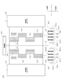
図3に示すように、キャリッジ部22の筐体は、液滴26を吐出するノズル列28を有する4つずつの記録ヘッド30、32と、すべての記録ヘッド30、32を保持する平面視矩形状のヘッドホルダ34と、ヘッドホルダ34の両側に配される一対の後処理ユニット36、38を固定しながら収容する。
As shown in FIG. 3, the casing of the
記録ヘッド30、32及び後処理ユニット36、38は、装置本体14が備える制御部40にそれぞれ電気的に接続されている。制御部40は、CPU(Central Processing Unit;中央処理装置)、RAM(Random Access Memory)を含んで構成され、記録ヘッド30、32の吐出制御、後処理ユニット36、38の照射制御を含む各種制御を実行する。
The recording heads 30 and 32 and the
記録ヘッド30、32はそれぞれ、X方向に沿って延びる4つのノズル列28から4色インク(CMYK)の液滴26を吐出する。記録ヘッド30、32による液滴26の吐出機構として種々の方式を採ってもよい。例えば、圧電素子を含んで構成されるアクチュエータの変形によって液滴26を吐出する方式を適用してもよい。また、ヒータ(発熱体)を介してインクを加熱することで気泡を発生させ、その圧力で液滴26を吐出する方式を適用してもよい。
Each of the recording heads 30 and 32 ejects
後処理ユニット36、38はそれぞれ、記録媒体12上の液滴26に向けて紫外線を照射する光源ユニットで構成されると共に、平面視にて概略矩形状を有する。紫外線を発する光源は、希ガス放電灯、水銀放電灯、蛍光灯ランプ、LED(Light Emitting Diode)アレイ等で構成される。
Each of the
後処理ユニット36、38は、X方向に沿って互いに平行に、且つ、すべての記録ヘッド30、32を挟んで配置される。以下、後処理ユニット36の記録ヘッド32に近い側のエッジを「処理開始線E1」とし、後処理ユニット38の記録ヘッド30に近い側のエッジを「処理開始線E2」とする。このとき、処理開始線E1、E2の中間線は直線であり、且つ、後処理ユニット36、38の「中心線C」に相当する。
The
本図から理解されるように、複数(合計8つ)の記録ヘッド30、32は、中心線Cに対して対称となる位置関係下に配置されている。中心線Cに対して対称であり、且つ、X方向の位置が等しい記録ヘッド30、32同士を「ペア」と称する場合、ヘッドホルダ34には4組の「ペア」が存在する。
As can be understood from the drawing, the plurality of (eight in total) recording heads 30 and 32 are arranged under a positional relationship that is symmetric with respect to the center line C. When the recording heads 30 and 32 that are symmetrical with respect to the center line C and have the same position in the X direction are referred to as “pairs”, there are four “pairs” in the
記録ヘッド30の右側から1番目のノズル列28は、イエローインクの液滴26を吐出する複数のノズル42yが等間隔に配置されてなる。右側から2番目のノズル列28は、シアンインクの液滴26を吐出する複数のノズル42cが等間隔に配置されてなる。右側から3番目のノズル列28は、マゼンタインクの液滴26を吐出する複数のノズル42mが等間隔に配置されてなる。右側から4番目のノズル列28は、ブラックインクの液滴26を吐出する複数のノズル42kが等間隔に配置されてなる。以下、二次元格子状に配置されたノズル42y、42c、42m、42kの集合を「ノズル行列44」と称する場合がある。
The
ここで、中心線Cに近い位置のノズル列28ほど明度が低い色(ブラック)であり、中心線Cから遠い位置のノズル列28ほど明度が高い色(イエロー)であることが好ましい。なお、本明細書中の「明度」は、色の明るさを表し、例えば、CIELAB、CIELUVを含む表色系において0〜100の範囲内のいずれかの値を採る指標である。
Here, it is preferable that the
本図例では、4つの記録ヘッド30が、X方向に沿って2列交互にスタガ配置(いわゆる千鳥配置)されている。これにより、4つ分のノズル列28を構成するノズル42k(42m、42c、42y)は、X方向の位置に関して等間隔に配置される。このように、複数の記録ヘッド30をY方向にずらして配置することで、キャリッジ部22の1回の走査にて得られる印刷領域(X方向の幅)を拡大可能である。
In the illustrated example, four recording heads 30 are staggered (so-called staggered arrangement) alternately in two rows along the X direction. Accordingly, the nozzles 42k (42m, 42c, 42y) constituting the four
一方、記録ヘッド32の左側から1番目のノズル列28は、イエローインクの液滴26を吐出する複数のノズル42yが等間隔に配置されてなる。左側から2番目のノズル列28は、シアンインクの液滴26を吐出する複数のノズル42cが等間隔に配置されてなる。左側から3番目のノズル列28は、マゼンタインクの液滴26を吐出する複数のノズル42mが等間隔に配置されてなる。左側から4番目のノズル列28は、ブラックインクの液滴26を吐出する複数のノズル42kが等間隔に配置されてなる。つまり、記録ヘッド32のノズル行列44は、記録ヘッド30のノズル行列44に対して線対称の関係にある。
On the other hand, the
このように構成しているので、「ブラック」インクの液滴26を吐出するノズル群が2つ存在すると共に、この2つのノズル群46、48(図4参照)は、中心線Cに対して対称となる位置関係下にある。ここで、「ノズル群」とは、1つ又は2つ以上のノズル列28からなり、X方向の位置に関して等間隔に配置されたノズル42kの集合である。なお、その他の3色、具体的にはマゼンタ、シアン及びイエローについても同じである。この実施形態では、同色の液滴26を吐出するノズル群はいずれも、中心線Cに対して対称(つまり、線対称)になるように配置される。
With this configuration, there are two nozzle groups that eject the droplets of “black”
なお、後処理ユニット36が有するX方向の長さは、複数の記録ヘッド30、32が1回の走査にて吐出可能であるX方向の範囲(以下、吐出可能範囲)よりも大きい。この吐出可能範囲は、1つのノズル群46(48)に属する2つ以上の記録ヘッド30(32)のうち、X方向の最も上流側にあるノズル42kと、最も下流側にあるノズル42kの間の距離に相当する。また、後処理ユニット38が有するX方向の長さは、後処理ユニット36と同様に、複数の記録ヘッド30、32による吐出可能範囲よりも大きい。
Note that the length in the X direction of the
<インクジェット記録装置10の動作>
第1実施形態に係るインクジェット記録装置10は以上のように構成される。続いて、インクジェット記録装置10の動作について、図4を参照しながら説明する。
<Operation of
The ink
制御部40(図3)は、外部から入力された画像信号を所望の印刷用データに変換した後、この印刷用データに基づいて記録ヘッド30、32の制御信号を生成する。これにより、インクジェット記録装置10は、記録媒体12の上にカラー画像を形成するための印刷処理を施す。
The control unit 40 (FIG. 3) converts an externally input image signal into desired print data, and then generates a control signal for the recording heads 30 and 32 based on the print data. Thereby, the
この印刷処理の際に、片方向記録モード・双方向記録モードを含む記録モードの選択がなされる。ここで、「片方向記録モード」とは、キャリッジ部22の往路走査(矢印Y1方向の走査)にて液滴26を吐出するが、その復路走査(矢印Y2方向の走査)にて液滴26を吐出しないモードである。一方、「双方向記録モード」とは、キャリッジ部22の往路走査及び復路走査にて液滴26を吐出するモードである。
During this printing process, a recording mode including a unidirectional recording mode and a bidirectional recording mode is selected. Here, in the “one-way recording mode”, the
図4は、第1実施形態における双方向記録モード時の画像形成プロセスを示す説明図である。具体的には、図4Aは往路走査(矢印Y1方向)時の説明図であり、図4Bは復路走査(矢印Y2方向)時の説明図である。これらの図では、特定色(例えば、ブラック)の液滴26を吐出するノズル列28、後処理ユニット36、38の位置関係のみを模式的に示している。
FIG. 4 is an explanatory diagram showing an image forming process in the bidirectional recording mode in the first embodiment. Specifically, FIG. 4A is an explanatory diagram during forward scanning (in the direction of arrow Y1), and FIG. 4B is an explanatory diagram during backward scanning (in the direction of arrow Y2). In these drawings, only the positional relationship between the
図4Aに示すように、往路走査(矢印Y1方向)を行った場合に、ノズル群46、48から吐出された液滴26は、記録媒体12の一面に着弾し、時間の経過につれて該一面に沿って徐々に流動する。その後、キャリッジ部22が矢印Y1方向に移動することで、後処理ユニット36は液滴26の着弾位置に到達する。後処理ユニット36は、制御部40からの照射制御に応じて紫外線を照射することで、液滴26を硬化させる後処理を実行する。
As shown in FIG. 4A, when forward scanning (in the direction of arrow Y1) is performed, the
ここで、ノズル群46のうちX方向の下流側から1番目のノズル列28と処理開始線E1の間の距離をD1とし、2番目のノズル列28と処理開始線E1の間の距離をD2(<D1)とする。また、ノズル群48のうちX方向の下流側から3番目のノズル列28と処理開始線E1の間の距離をD3とし、4番目のノズル列28と処理開始線E1の間の距離をD4(<D3)とする。キャリッジ部22は等速で移動するので、距離D4の液滴26は、距離D3の液滴26よりも、着弾時点から後処理の開始時点までの待ち時間が長くなる。
Here, the distance between the
そうすると、ノズル群46、48から吐出された液滴26は、記録媒体12の一面に着弾し、時間の経過につれて該一面に沿って徐々に流動する。その後、キャリッジ部22が矢印Y2方向に移動することで、後処理ユニット38は液滴26の着弾位置に到達する。後処理ユニット38は、制御部40からの照射制御に応じて紫外線を照射することで、液滴26を硬化させる後処理を実行する。
Then, the
ここで、ノズル群48のうちX方向の下流側から1番目のノズル列28と処理開始線E2の間の距離はD1であり、2番目のノズル列28と処理開始線E2の間の距離はD2であり、往路走査時(図4A)の場合と同じになる。同様に、ノズル群46のうちX方向の下流側から3番目のノズル列28と処理開始線E2の間の距離はD3であり、4番目のノズル列28と処理開始線E2の間の距離はD4であり、往路走査時(図4A)の場合と同じになる。
Here, the distance between the
その後、制御部40は、搬送ローラ18を駆動制御することで記録媒体12を1パス分だけ搬送させた後、上記した動作を繰り返し実行させる。インクジェット記録装置10は、記録媒体12を搬送方向(X方向)に移動させ、且つ、キャリッジ部22を搬送方向に交わる方向(Y方向)に沿って等速で往復移動させながら、往路走査(矢印Y1方向)及び復路走査(矢印Y2方向)のタイミングにて液滴26を吐出することで、ドットにより記録媒体12上に画像を形成する。
Thereafter, the
<第1実施形態による効果>
以上のように、インクジェット記録装置10は、インクの液滴26を吐出する2つ以上のノズル列28をそれぞれ有する複数の記録ヘッド30、32と、複数の記録ヘッド30、32から記録媒体12に向けて吐出された液滴26に紫外線を照射することで、インクによって形成された各ドットに対して後処理を実行する一対の後処理ユニット36、38と、複数の記録ヘッド30、32をY方向に沿って往復移動させながら、往路走査及び復路走査のタイミングにて液滴26を吐出することで、各ドットにより記録媒体12上に画像を形成させる制御部40を備える。
<Effects of First Embodiment>
As described above, the
複数の記録ヘッド30(32)は、X方向及びY方向においてそれぞれ2つ以上配置されたスタガ配置を構成する。一対の後処理ユニット36、38は、X方向に沿って互いに平行に、且つ、複数の記録ヘッド30、32を挟んで配置される。一対の後処理ユニット36、38がそれぞれ有するX方向の長さは、複数の記録ヘッド30、32が1回の走査にて吐出可能であるX方向の範囲以上である。そして、同色(例えばブラック)の液滴26を吐出する2つ以上のノズル列(ノズル群46、48)が一対の後処理ユニット36、38間の中心線Cに対して対称となるように、複数の記録ヘッド30、32が配置される。
The plurality of recording heads 30 (32) constitutes a staggered arrangement in which two or more are arranged in the X direction and the Y direction, respectively. The pair of
このように構成されるので、ノズル群46及び後処理ユニット36の間の距離と、ノズル群48及び後処理ユニット38の間の距離が等しくなると共に、ノズル群48及び後処理ユニット36の間の距離と、ノズル群46及び後処理ユニット36の間の距離が等しくなる。つまり、往路走査及び復路走査にかかわらず、液滴26の着弾時点から後処理の開始時点までの待ち時間が略一定になる。
With this configuration, the distance between the
また、複数の記録ヘッド30(32)のうち2つ以上のスタガ配置によってノズル群46(48)同士の配置対称性を担保するので、記録ヘッド30、32の配置や個数が変更された場合であっても、一対の後処理ユニット36、38の設計上の干渉がないか軽微である。これにより、後処理に起因する画像全体の不均質を抑制しつつも、後処理ユニット36、38の形状及び配置を容易に設計できる。
Further, since the arrangement symmetry of the nozzle groups 46 (48) is ensured by the arrangement of two or more staggers among the plurality of recording heads 30 (32), the arrangement and the number of the recording heads 30 and 32 are changed. Even if it exists, there is no interference in the design of a pair of
また、ノズル群46、48は、複数の記録ヘッド30、32のうち2つ以上のスタガ配置により構成されているので、個々の記録ヘッド30、32に設けるノズルの個数を低減可能となり、その結果、記録ヘッド30、32の生産性(例えば歩留まり)が向上する。
Further, since the
また、複数の記録ヘッド30、32には、異なる色の液滴26を吐出する2つ以上のノズル列28が互いに平行に配置された記録ヘッド30、32のペアが少なくとも1組含まれ、液滴26の色毎に、2つ以上のノズル列28が中心線Cに対して対称となるように、記録ヘッド30、32のペアが配置されてもよい。複数の色が混在する場合であっても、同色の液滴26を吐出する2つ以上のノズル列28が中心線Cに対して対称になるように配置されるので、同じ色同士において、液滴26の着弾時点から後処理の開始時点までの待ち時間が略一定になる。
Further, the plurality of recording heads 30 and 32 include at least one pair of recording heads 30 and 32 in which two or
また、記録ヘッド30、32のペアは、中心線Cに近い位置のノズル列28ほど明度が低い色の液滴26を吐出し、中心線Cから遠い位置のノズル列28ほど明度が高い色の液滴26を吐出するようにしてもよい。中心線Cに近い位置のノズル列28ほど後処理の開始時点までの待ち時間が短くなり、中心線Cから遠い位置のノズル列28ほどこの待ち時間が長くなる。また、待ち時間が十分に短い場合には液滴26の流動に起因するビーディングが起こり難い一方、待ち時間が長くなるにつれてビーディングが起こり易くなる傾向がある。そこで、視認性が相対的に高い低明度色の液滴26を、中心線Cに近い位置のノズル列28から吐出することで、ビーディングが引き起こす画質の低下を抑制できる。
Further, the pair of recording heads 30 and 32 ejects a
また、複数の記録ヘッド30、32及び一対の後処理ユニット36、38を固定配置するキャリッジ部22を設けてもよい。これにより、複数の記録ヘッド30、32及び一対の後処理ユニット36、38を一体的に移動させることができる。
In addition, a
[第1実施形態の変形例]
続いて、第1実施形態に係るインクジェット記録装置10の変形例について、図5〜図9を参照しながら説明する。なお、第1実施形態と同様の構成要素については、同一の参照符号を付すると共にその説明を省略する。
[Modification of First Embodiment]
Next, modified examples of the ink
<第1変形例>
図5は、第1変形例に係るキャリッジ部52の概略平面透視図である。キャリッジ部52のヘッドホルダ54は、第1実施形態(図3)と同様に、中心線Cに対して対称になる位置関係下に、4つずつの記録ヘッド30、32を保持する。ところが、4つの記録ヘッド30はX方向に沿った3列のスタガ配置であると共に、4つの記録ヘッド32はX方向に沿った3列のスタガ配置である。このように、3列又はそれ以上のスタガ配置によりノズル群46、48(図3)を構成しても、第1実施形態と同様の作用効果が得られる。
<First Modification>
FIG. 5 is a schematic plan perspective view of the
ところで、X方向の最も下流側にある記録ヘッド32の、後処理ユニット36に近い側のエッジと、処理開始線E1の間の距離はDである。同様に、X方向の最も下流側にある記録ヘッド30の、後処理ユニット38に近い側のエッジと、処理開始線E2の間の距離はDである。
Incidentally, the distance between the edge of the
ここで、最も下流側にある記録ヘッド32は、往路走査(矢印Y1方向)にて画像の最上層を形成する液滴26を吐出することとなる。また、最も下流側にある記録ヘッド30は、復路走査(矢印Y2方向)にて画像の最上層を形成する液滴26を吐出することとなる。
Here, the
キャリッジ部22が等速で移動する場合、記録ヘッド32、30と処理開始線E1、E2間の距離Dは、着弾時点から後処理の開始時点までの待ち時間に比例する。つまり、距離Dを長くすれば粒状感が少ないグロス調の画像が得られると共に、距離Dを短くすれば鮮鋭感の高いマット調の画像が得られる。
When the
<第2変形例>
図6は、第2変形例に係るキャリッジ部62の概略平面透視図である。キャリッジ部62のヘッドホルダ64は、第1実施形態(図3)の場合と同様に、中心線Cに対して対称になる位置関係下に、4つずつの記録ヘッド30、32を保持する。ところが、4つの記録ヘッド30は、X方向の下流側から上流側にわたって、中心線Cから徐々に近接するように配置されている。4つの記録ヘッド32は、「ペア」となる記録ヘッド30との間の対称性を維持しながら、X方向の下流側から上流側にわたって、中心線Cから徐々に近接するように配置されている。
<Second Modification>
FIG. 6 is a schematic plan perspective view of the
このように、複数組の記録ヘッド30、32に関して、X方向の下流側に配置されるペアほど離間距離が長く、且つ、X方向の上流側に配置されるペアほど離間距離が短くなるように構成してもよい。記録ヘッド30、32のペアは、離間距離が長いほど中心線Cから遠く、且つ、後処理ユニット36、38に近い位置に配置されるので、後処理の開始時点までの待ち時間が短くなる。その結果、着弾後の液滴26の流動量が相対的に少なくなる。そこで、離間距離が相対的に長いペアをX方向の下流側に配置し、画像の上層を形成する液滴26の流動量を少なくすることで、鮮鋭感が高いマット調の画像が得られる。
As described above, with respect to the plural sets of recording heads 30 and 32, the pair arranged on the downstream side in the X direction has a longer separation distance, and the pair arranged on the upstream side in the X direction has a shorter separation distance. It may be configured. Since the pair of the recording heads 30 and 32 is arranged at a position farther from the center line C and closer to the
<第3変形例>
図7は、第3変形例に係るキャリッジ部72の概略平面透視図である。キャリッジ部72のヘッドホルダ74は、第1実施形態(図3)の場合と同様に、中心線Cに対して対称になる位置関係下に、4つずつの記録ヘッド30、32を保持する。ところが、4つの記録ヘッド30は、X方向の下流側から上流側にわたって、中心線Cから徐々に離間するように配置されている。4つの記録ヘッド32は、「ペア」となる記録ヘッド30との間の対称性を維持しながら、X方向の下流側から上流側にわたって、中心線Cから徐々に離間するように配置されている。
<Third Modification>
FIG. 7 is a schematic plan perspective view of the
このように、複数組の記録ヘッド30、32に関して、X方向の下流側に配置されるペアほど離間距離が短く、且つ、X方向の上流側に配置されるペアほど離間距離が長くなるように構成してもよい。記録ヘッド30、32のペアは、離間距離が短いほど中心線Cに近く、且つ、後処理ユニット36、38から遠い位置に配置されるので、後処理の開始時点までの待ち時間が長くなる。その結果、着弾後の液滴26の流動量が相対的に多くなる。そこで、離間距離が相対的に短いペアをX方向の下流側に配置し、画像の上層を形成する液滴26の流動量を多くすることで、粒状感が少ないグロス調の画像が得られる。
As described above, with respect to a plurality of sets of recording heads 30 and 32, the pair arranged on the downstream side in the X direction has a shorter separation distance, and the pair arranged on the upstream side in the X direction has a longer separation distance. It may be configured. Since the pair of the recording heads 30 and 32 is arranged closer to the center line C and farther from the
<第4変形例>
図8は、第4変形例に係るキャリッジ部82の概略平面透視図である。キャリッジ部82のヘッドホルダ84は、中心線Cに対して対称になる位置関係下に、6つずつの記録ヘッド30、32を保持する。このように、Y方向の位置が等しい「ペア」が複数組存在するように構成しても、第1実施形態と同様の作用効果が得られる。特に、インク(液滴26)の色数が多い場合であっても、比較的コンパクトな構成で画質全体の不均質を抑制しつつ、双方向記録モードを実現することができる。
<Fourth Modification>
FIG. 8 is a schematic plan perspective view of the
<第5変形例>
図9は、第5変形例に係るキャリッジ部92の概略平面透視図である。キャリッジ部92のヘッドホルダ94は、3つずつの記録ヘッド30、32と、2つの記録ヘッド96を保持する。3つの記録ヘッド30はX方向に沿って2列交互にスタガ配置されると共に、3つの記録ヘッド32はX方向に沿って2列交互にスタガ配置されている。2つの記録ヘッド96はそれぞれ、幅方向の中心軸と、後処理ユニット36、38間の中心線Cが一致するように配置されている。
<Fifth Modification>
FIG. 9 is a schematic plan perspective view of the
記録ヘッド96はそれぞれ、X方向に沿って延びる4つのノズル列28から2色インク(W、CL)の液滴26を吐出する。インクの色は、W(ホワイト)、CL(クリア)の他、プロセスカラー(CMYK)の同系色、或いは、ゴールド・シルバー・オレンジ・バイオレット等のスポットカラーであってもよい。
Each of the recording heads 96 ejects
記録ヘッド96の右側から1番目のノズル列28は、ホワイトインクの液滴26を吐出する複数のノズル42wが等間隔に配置されてなる。右側から2番目のノズル列28は、クリアインクの液滴26を吐出する複数のノズル42clが等間隔に配置されてなる。右側から3番目のノズル列28は、クリアインクの液滴26を吐出する複数のノズル42clが等間隔に配置されてなる。右側から4番目のノズル列28は、ホワイトインクの液滴26を吐出する複数のノズル42wが等間隔に配置されてなる。
The
本変形例において、6色のインクの液滴26を吐出するノズル群がそれぞれ2つ存在すると共に、2つのノズル群は中心線Cに対して対称となる位置関係下にある。ここで6色とは、ブラック、マゼンタ、シアン、イエローの他、ホワイト、クリアである。 In this modified example, there are two nozzle groups each ejecting ink droplets 6 of six colors, and the two nozzle groups are in a positional relationship that is symmetrical with respect to the center line C. Here, the six colors are black, magenta, cyan, yellow, white, and clear.
このように、複数の記録ヘッド30、32、96には、同色の液滴26を吐出する2つ以上のノズル列28が互いに平行に配置された特定の記録ヘッド96が少なくとも1つ含まれてもよい。この場合、特定の記録ヘッド96は、2つ以上のノズル列28が中心線Cに対して対称となるように配置される。1つの記録ヘッド96のみを用いてノズル列28の配置対称性を実現可能となり、2つ以上を用いる場合と比べて、記録ヘッド96の位置・姿勢の調整作業が容易になる。
As described above, the plurality of recording heads 30, 32, and 96 include at least one
<第6変形例>
後処理ユニット36、38は、液滴26にエネルギーを付与することで、インクのドットに対して後処理、具体的には流動性を有するインクの流動性を無くす処理、或いは、低下させる処理を実行するものであればよい。エネルギーは、紫外線を含む電磁波(光エネルギー)のみならず、熱エネルギーであってもよい。例えば、溶媒を含有するインクに対して加熱することで溶媒を揮発させてインクの流動性を無くしたい場合には、後処理ユニット36にヒータを搭載すればよい。
<Sixth Modification>
The
[第2実施形態]
続いて、第2実施形態に係るインクジェット記録装置110について、図1、図2、図10及び図11を参照しながら説明する。
[Second Embodiment]
Next, an
<インクジェット記録装置110の構成>
図1及び図2に示すように、インクジェット記録装置110の構成は、キャリッジ部22に代わってキャリッジ部112(図10参照)を備える点が、第1実施形態と異なっている。その他の構成要素については第1実施形態と基本的に同じであるため、その説明を省略する。
<Configuration of
As shown in FIGS. 1 and 2, the configuration of the ink
<キャリッジ部112の構成>
図10は、第2実施形態に係るキャリッジ部112の概略平面透視図である。キャリッジ部112の筐体は、ノズル列28を有する4つずつの記録ヘッド30、32と、略中央に配される後処理ユニット114と、4つの記録ヘッド30を保持する平面視矩形状のヘッドホルダ116と、4つの記録ヘッド32を保持する平面視矩形状のヘッドホルダ118を固定しながら収容する。
<Configuration of
FIG. 10 is a schematic plan perspective view of the
記録ヘッド30、32及び後処理ユニット114は、装置本体14が備える制御部140にそれぞれ電気的に接続されている。制御部140は、CPU、RAMを含んで構成され、記録ヘッド30、32の吐出制御、後処理ユニット114の照射制御を含む各種制御を実行する。
The recording heads 30 and 32 and the
記録ヘッド30、32はそれぞれ、Y方向に沿って延びる4つのノズル列28から4色インク(CMYK)の液滴26を吐出する。後処理ユニット114は、記録媒体12上の液滴26に向けて紫外線を照射する光源ユニットで構成されると共に、平面視にて概略矩形状を有する。記録ヘッド30、32、及び後処理ユニット114は、第1実施形態と同様の構成を採用してもよい。
Each of the recording heads 30 and 32 ejects
後処理ユニット114は、X方向に沿って直線状に配置される。以下、後処理ユニット114の記録ヘッド30に近い側のエッジを「処理開始線E1」とし、後処理ユニット114の記録ヘッド32に近い側のエッジを「処理開始線E2」とする。このとき、処理開始線E1、E2の中間線は直線であり、且つ、後処理ユニット114の「中心線C」に相当する。
The
本図から理解されるように、複数(合計8つ)の記録ヘッド30、32は、中心線Cに対して対称となるように配置されている。記録ヘッド30、32、ノズル列28の形状的及び配置的特徴については、第1実施形態(図3参照)と基本的に同じである。すなわち、同色のインクの液滴26を吐出するノズル群46、48が2つ存在すると共に、これらのノズル群46、48(図11参照)は、中心線Cに対して対称となる位置関係下にある。
As can be understood from the drawing, the plurality of (eight in total) recording heads 30 and 32 are arranged so as to be symmetric with respect to the center line C. The shape and arrangement characteristics of the recording heads 30 and 32 and the
なお、後処理ユニット114が有するX方向の長さは、複数の記録ヘッド30、32が1回の走査にて吐出可能であるX方向の範囲(つまり、吐出可能範囲)よりも大きい。この吐出可能範囲は、1つのノズル群46(48)に属する2つ以上の記録ヘッド30(32)のうち、X方向の最も上流側にあるノズル42kと、最も下流側にあるノズル42kの間の距離に相当する。
Note that the length in the X direction of the
<インクジェット記録装置110の動作>
第2実施形態に係るインクジェット記録装置110は以上のように構成される。続いて、インクジェット記録装置110の動作について、図11を参照しながら説明する。
<Operation of
The ink
制御部120(図10)は、外部から入力された画像信号を所望の印刷用データに変換した後、この印刷用データに基づいて記録ヘッド30、32の制御信号を生成する。これにより、インクジェット記録装置110は、記録媒体12の上にカラー画像を形成するための印刷処理を施す。この印刷処理の際に、片方向記録モード・双方向記録モードを含む記録モードの選択がなされる。
The controller 120 (FIG. 10) converts an image signal input from the outside into desired print data, and then generates control signals for the recording heads 30 and 32 based on the print data. Thereby, the ink
図11は、第2実施形態における双方向記録モード時の画像形成プロセスを示す説明図である。具体的には、図11Aは往路走査(矢印Y1方向)時の説明図であり、図11Bは復路走査(矢印Y2方向)時の説明図である。これらの図では、特定色(例えば、ブラック)の液滴26を吐出するノズル列28、後処理ユニット114の位置関係のみを模式的に示している。中心線Cは、後処理ユニット114の幅(2ΔD)を二等分する線に相当する。
FIG. 11 is an explanatory diagram showing an image forming process in the bidirectional recording mode in the second embodiment. Specifically, FIG. 11A is an explanatory diagram during forward scanning (in the direction of arrow Y1), and FIG. 11B is an explanatory diagram during backward scanning (in the direction of arrow Y2). In these drawings, only the positional relationship between the
図11Aでは、キャリッジ部112の往路走査時に液滴26を吐出するノズル列28、つまり、処理開始線E1に近い側(ノズル群46)を実線で示している。一方、キャリッジ部112の往路走査時に液滴26を吐出しないノズル列28、つまり、処理開始線E2に近い側(ノズル群48)を一点鎖線で示している。
In FIG. 11A, the
そうすると、ノズル群46から吐出された液滴26は、記録媒体12の一面に着弾し、時間の経過につれて該一面に沿って徐々に流動する。その後、キャリッジ部112が矢印Y1方向に移動することで、後処理ユニット114は液滴26の着弾位置に到達する。後処理ユニット114は、制御部140による照射制御に応じて紫外線を照射することで、液滴26を硬化させる後処理を実行する。ここで、ノズル群46のうちX方向の下流側から1番目のノズル列28と処理開始線E1の間の距離をD5とし、2番目のノズル列28と処理開始線E1の間の距離をD6(<D5)とする。
Then, the
図11Bでは、キャリッジ部112の復路走査時に液滴26を吐出するノズル群48を実線で示している。一方、キャリッジ部112の復路走査時に液滴26を吐出しないノズル群46を一点鎖線で示している。
In FIG. 11B, the
そうすると、ノズル群48から吐出された液滴26は、記録媒体12の一面に着弾し、時間の経過につれて該一面に沿って徐々に流動する。その後、キャリッジ部112が矢印Y2方向に移動することで、後処理ユニット114は液滴26の着弾位置に到達する。後処理ユニット114は、制御部140による照射制御に応じて紫外線を照射することで、液滴26を硬化させる後処理を実行する。
Then, the
ここで、ノズル群48のうちX方向の下流側から1番目のノズル列28と処理開始線E2の間の距離(D5)は、往路走査時(図11A)の場合と同じになる。同様に、ノズル群48のうちX方向の下流側から2番目のノズル列28と処理開始線E2の間の距離(D6)は、往路走査時(図11A)の場合と同じになる。
Here, the distance (D5) between the
<第2実施形態による効果>
以上のように、インクジェット記録装置110は、インクの液滴を吐出する2つ以上のノズル列28をそれぞれ有する複数の記録ヘッド30、32と、複数の記録ヘッド30、32から記録媒体12に向けて吐出された液滴26に紫外線を照射することで、インクによって形成された各ドットに対して後処理を実行する後処理ユニット114と、複数の記録ヘッド30、32をY方向に沿って往復移動させながら、往路走査及び復路走査のタイミングにて液滴26を吐出することで、各ドットにより記録媒体12上に画像を形成させる制御部120を備える。
<Effects of Second Embodiment>
As described above, the
複数の記録ヘッド30(32)は、X方向及びY方向においてそれぞれ2つ以上配置されたスタガ配置を構成する。後処理ユニット114は、X方向に沿って直線状に配置される。後処理ユニット114が有するX方向の長さは、複数の記録ヘッド30、32が1回の走査にて吐出可能であるX方向の範囲以上である。そして、同色(例えばブラック)の液滴26を吐出する2つ以上のノズル列(ノズル群46、48)が後処理ユニット114の中心線Cに対して対称となるように、複数の記録ヘッド30、32が配置される。
The plurality of recording heads 30 (32) constitutes a staggered arrangement in which two or more are arranged in the X direction and the Y direction, respectively. The
このように構成されるので、中心線Cの一方側にあるノズル群46と後処理ユニット114の間の距離は、他方側にあるノズル群48と後処理ユニット114の間の距離に等しくなる。つまり、往路走査及び復路走査にかかわらず、液滴26の着弾時点から後処理の開始時点までの待ち時間が略一定になる。
With this configuration, the distance between the
また、複数の記録ヘッド30(32)のうち2つ以上のスタガ配置によってノズル群46(48)同士の配置対称性を担保するので、記録ヘッド30、32の配置や個数が変更された場合であっても、後処理ユニット114の設計上の干渉がないか軽微である。これにより、後処理に起因する画像全体の不均質を抑制しつつも、後処理ユニット114の形状及び配置を容易に設計できる。
Further, since the arrangement symmetry of the nozzle groups 46 (48) is ensured by the arrangement of two or more staggers among the plurality of recording heads 30 (32), the arrangement and the number of the recording heads 30 and 32 are changed. Even if it exists, there is no interference in the design of the
[第2実施形態の変形例]
第2実施形態に係るインクジェット記録装置110に対して、技術的に矛盾しない限りにおいて、上述の第1〜第6変形例の各構成を適宜組み合わせてもよい。具体的には、第1変形例(図5)、第2変形例(図6)、第3変形例(図7)、第4変形例(図8)及び第6変形例を適用できる。
[Modification of Second Embodiment]
As long as there is no technical contradiction for the
[備考]
なお、この発明は、上述した実施形態及び変形例に限定されるものではなく、この発明の主旨を逸脱しない範囲で自由に変更できることは勿論である。
[Remarks]
Note that the present invention is not limited to the above-described embodiments and modifications, and can of course be freely changed without departing from the gist of the present invention.
10、110‥インクジェット記録装置 12‥記録媒体
14‥装置本体 16‥巻取装置
18‥搬送ローラ 20‥プラテン
22、52、62、72、82、92、112‥キャリッジ部
24‥ガイドレール 26‥液滴
28‥ノズル列 30、32、96‥記録ヘッド
36、38、114‥後処理ユニット 40、120‥制御部
46、48‥ノズル群 C‥中心線
X‥副走査方向(第2方向) Y‥主走査方向(第1方向)
DESCRIPTION OF
Claims (8)
前記複数の記録ヘッドから記録媒体に向けて吐出された前記液滴にエネルギーを付与することで、前記インクによって形成された各ドットに対して後処理を実行する一対の後処理ユニットと、
前記複数の記録ヘッドを第1方向に沿って往復移動させながら、往路走査及び復路走査のタイミングにて前記液滴を吐出することで、前記各ドットにより前記記録媒体上に画像を形成させる制御部と
を備え、
前記複数の記録ヘッドは、前記第1方向及び該第1方向に交差する第2方向においてそれぞれ2つ以上配置されたスタガ配置を構成し、
前記一対の後処理ユニットは、前記第2方向に沿って互いに平行に、且つ、前記複数の記録ヘッドを挟んで配置され、
前記一対の後処理ユニットがそれぞれ有する前記第2方向の長さは、前記複数の記録ヘッドが1回の走査にて吐出可能である前記第2方向の範囲以上であり、
同色の前記液滴を吐出する2つ以上の前記ノズル列が前記一対の後処理ユニット間の中心線に対して対称となるように、前記複数の記録ヘッドが配置される
ことを特徴とするインクジェット記録装置。 A plurality of recording heads each having at least one nozzle row for discharging ink droplets;
A pair of post-processing units that perform post-processing on each dot formed by the ink by applying energy to the droplets ejected from the plurality of recording heads toward the recording medium;
A controller that forms an image on the recording medium by the dots by ejecting the liquid droplets at the timing of forward scanning and backward scanning while reciprocating the plurality of recording heads along the first direction. And
The plurality of recording heads constitute a staggered arrangement in which two or more are arranged in each of the first direction and the second direction intersecting the first direction,
The pair of post-processing units are arranged in parallel to each other along the second direction and sandwiching the plurality of recording heads,
The length in the second direction that each of the pair of post-processing units has is equal to or greater than the range in the second direction in which the plurality of recording heads can discharge in one scan,
The plurality of recording heads are arranged such that two or more nozzle arrays that discharge the same color droplets are symmetrical with respect to a center line between the pair of post-processing units. Recording device.
前記液滴の色毎に、2つ以上の前記ノズル列が前記中心線に対して対称となるように、前記記録ヘッドのペアが配置される
ことを特徴とする請求項1に記載のインクジェット記録装置。 The plurality of recording heads include at least one pair of recording heads in which two or more nozzle arrays that discharge the droplets of different colors are arranged in parallel to each other,
2. The ink jet recording according to claim 1, wherein the pair of recording heads is arranged so that two or more nozzle arrays are symmetrical with respect to the center line for each color of the droplet. apparatus.
前記第2方向の下流側に配置される前記記録ヘッドのペアほど離間距離が長く、且つ、前記第2方向の上流側に配置される前記記録ヘッドのペアほど離間距離が短い
ことを特徴とする請求項2に記載のインクジェット記録装置。 The plurality of recording heads includes a plurality of pairs of the recording heads,
The pair of recording heads arranged on the downstream side in the second direction has a longer separation distance, and the pair of recording heads arranged on the upstream side in the second direction has a shorter separation distance. The ink jet recording apparatus according to claim 2.
前記第2方向の下流側に配置される前記記録ヘッドのペアほど離間距離が短く、且つ、前記第2方向の上流側に配置される前記記録ヘッドのペアほど離間距離が長い
ことを特徴とする請求項3に記載のインクジェット記録装置。 The plurality of recording heads includes a plurality of pairs of the recording heads,
The pair of recording heads arranged on the downstream side in the second direction has a shorter separation distance, and the pair of recording heads arranged on the upstream side in the second direction has a longer separation distance. The ink jet recording apparatus according to claim 3.
2つ以上の前記ノズル列が前記中心線に対して対称となるように、前記特定の記録ヘッドが配置される
ことを特徴とする請求項1〜5のいずれか1項に記載のインクジェット記録装置。 The plurality of recording heads include at least one specific recording head in which two or more nozzle arrays that discharge the droplets of the same color are arranged in parallel to each other;
The inkjet recording apparatus according to claim 1, wherein the specific recording head is arranged so that two or more nozzle arrays are symmetrical with respect to the center line. .
Priority Applications (5)
| Application Number | Priority Date | Filing Date | Title |
|---|---|---|---|
| JP2015040773A JP6416660B2 (en) | 2015-03-02 | 2015-03-02 | Inkjet recording apparatus and inkjet recording method |
| CN201680013360.2A CN107405914B (en) | 2015-03-02 | 2016-03-02 | Ink-jet recording apparatus and ink jet recording method |
| US15/547,811 US10189258B2 (en) | 2015-03-02 | 2016-03-02 | Inkjet recording apparatus and inkjet recording method |
| EP16758940.7A EP3266614B1 (en) | 2015-03-02 | 2016-03-02 | Ink jet recording apparatus and ink jet recording method |
| PCT/JP2016/056373 WO2016140247A1 (en) | 2015-03-02 | 2016-03-02 | Ink jet recording apparatus and ink jet recording method |
Applications Claiming Priority (1)
| Application Number | Priority Date | Filing Date | Title |
|---|---|---|---|
| JP2015040773A JP6416660B2 (en) | 2015-03-02 | 2015-03-02 | Inkjet recording apparatus and inkjet recording method |
Publications (2)
| Publication Number | Publication Date |
|---|---|
| JP2016159530A JP2016159530A (en) | 2016-09-05 |
| JP6416660B2 true JP6416660B2 (en) | 2018-10-31 |
Family
ID=56846000
Family Applications (1)
| Application Number | Title | Priority Date | Filing Date |
|---|---|---|---|
| JP2015040773A Active JP6416660B2 (en) | 2015-03-02 | 2015-03-02 | Inkjet recording apparatus and inkjet recording method |
Country Status (5)
| Country | Link |
|---|---|
| US (1) | US10189258B2 (en) |
| EP (1) | EP3266614B1 (en) |
| JP (1) | JP6416660B2 (en) |
| CN (1) | CN107405914B (en) |
| WO (1) | WO2016140247A1 (en) |
Families Citing this family (6)
| Publication number | Priority date | Publication date | Assignee | Title |
|---|---|---|---|---|
| JP6988096B2 (en) * | 2017-01-31 | 2022-01-05 | セイコーエプソン株式会社 | Head unit and liquid discharge device |
| JP6969220B2 (en) * | 2017-08-17 | 2021-11-24 | セイコーエプソン株式会社 | Print control device, print device, control method of print control device, and program |
| JP2019130781A (en) * | 2018-01-31 | 2019-08-08 | パナソニックIpマネジメント株式会社 | Printing device and printing method |
| JP6888576B2 (en) * | 2018-03-26 | 2021-06-16 | ブラザー工業株式会社 | Image recording device |
| US11014360B2 (en) | 2018-07-31 | 2021-05-25 | Ricoh Company, Ltd. | Liquid discharge apparatus, liquid discharge method, and recording medium |
| JP2020138388A (en) * | 2019-02-27 | 2020-09-03 | 株式会社リコー | Liquid discharge device, liquid discharge method and program |
Family Cites Families (10)
| Publication number | Priority date | Publication date | Assignee | Title |
|---|---|---|---|---|
| JP3707558B2 (en) * | 2002-08-26 | 2005-10-19 | セイコーエプソン株式会社 | Liquid jet head |
| JP3665783B2 (en) * | 2002-12-03 | 2005-06-29 | 日亜化学工業株式会社 | LED unit |
| DE50307557D1 (en) * | 2002-12-12 | 2007-08-09 | Luescher Hans | Printing device and printing method for UV-curable ink |
| JP2005342970A (en) * | 2004-06-02 | 2005-12-15 | Roland Dg Corp | Ink head arrangement structure in inkjet printer |
| KR20080015798A (en) * | 2005-05-25 | 2008-02-20 | 아그파 그래픽스 엔브이 | Image printing method and system for improving image quality in dot matrix printer |
| JP5350584B2 (en) * | 2005-10-27 | 2013-11-27 | オセ−テクノロジーズ・ベー・ヴエー | Inkjet printing method and printer |
| JP2007144637A (en) * | 2005-11-24 | 2007-06-14 | Konica Minolta Holdings Inc | Inkjet recording method |
| US8684511B2 (en) * | 2011-08-25 | 2014-04-01 | Electronics For Imaging, Inc. | Ink jet UV pinning for control of gloss |
| JP6099959B2 (en) * | 2012-09-10 | 2017-03-22 | 株式会社ミマキエンジニアリング | Inkjet recording device |
| JP6155741B2 (en) * | 2013-03-25 | 2017-07-05 | セイコーエプソン株式会社 | Liquid ejecting apparatus and manufacturing method thereof |
-
2015
- 2015-03-02 JP JP2015040773A patent/JP6416660B2/en active Active
-
2016
- 2016-03-02 CN CN201680013360.2A patent/CN107405914B/en active Active
- 2016-03-02 US US15/547,811 patent/US10189258B2/en active Active
- 2016-03-02 WO PCT/JP2016/056373 patent/WO2016140247A1/en active Application Filing
- 2016-03-02 EP EP16758940.7A patent/EP3266614B1/en active Active
Also Published As
| Publication number | Publication date |
|---|---|
| WO2016140247A1 (en) | 2016-09-09 |
| EP3266614A1 (en) | 2018-01-10 |
| CN107405914B (en) | 2019-02-15 |
| EP3266614B1 (en) | 2020-07-15 |
| US20180009225A1 (en) | 2018-01-11 |
| JP2016159530A (en) | 2016-09-05 |
| US10189258B2 (en) | 2019-01-29 |
| CN107405914A (en) | 2017-11-28 |
| EP3266614A4 (en) | 2018-01-31 |
Similar Documents
| Publication | Publication Date | Title |
|---|---|---|
| JP6416660B2 (en) | Inkjet recording apparatus and inkjet recording method | |
| JP2016159531A (en) | Inkjet recording device and inkjet recording method | |
| JP2013256075A (en) | Inkjet recording apparatus and control method therefor | |
| JP5668462B2 (en) | Printing apparatus and printing method | |
| JP2016055463A (en) | Printer and method for manufacturing printed matter | |
| JP6434817B2 (en) | Printing apparatus and printing method | |
| JP5617588B2 (en) | Printing apparatus and printing method | |
| US8256875B2 (en) | Two pass print mode method and apparatus for limiting wind-related print defects | |
| US20200254759A1 (en) | Ink jet printing | |
| JP5848683B2 (en) | Image forming apparatus and image forming method | |
| JP6488803B2 (en) | Droplet ejection apparatus, mask pattern, and droplet ejection method | |
| JP6745364B2 (en) | Image forming apparatus, control apparatus, control method, and control program | |
| JP5972037B2 (en) | Inkjet recording apparatus and inkjet recording method | |
| JP2012218220A (en) | Liquid ejecting apparatus and liquid ejecting method | |
| US8926040B2 (en) | Printing device and printing method | |
| JP5714423B2 (en) | Inkjet recording apparatus and inkjet recording method | |
| JP2006312287A (en) | Printing device, computer program, printing system and printing method | |
| JP5835422B2 (en) | Printing apparatus and printing method | |
| JP2014097603A (en) | Ink jet recording device and recording control method | |
| JP5714424B2 (en) | Inkjet recording apparatus and inkjet recording method | |
| WO2015133598A1 (en) | Printing system and method | |
| JP2011020380A (en) | Recording head and method for manufacturing the same | |
| JP6186489B1 (en) | Inkjet printer | |
| JP2018089941A (en) | Inkjet printer | |
| JP6356417B2 (en) | Printing apparatus, printing head, and printing method |
Legal Events
| Date | Code | Title | Description |
|---|---|---|---|
| A621 | Written request for application examination |
Free format text: JAPANESE INTERMEDIATE CODE: A621 Effective date: 20171025 |
|
| A131 | Notification of reasons for refusal |
Free format text: JAPANESE INTERMEDIATE CODE: A131 Effective date: 20180618 |
|
| A521 | Request for written amendment filed |
Free format text: JAPANESE INTERMEDIATE CODE: A523 Effective date: 20180723 |
|
| TRDD | Decision of grant or rejection written | ||
| A01 | Written decision to grant a patent or to grant a registration (utility model) |
Free format text: JAPANESE INTERMEDIATE CODE: A01 Effective date: 20180918 |
|
| A61 | First payment of annual fees (during grant procedure) |
Free format text: JAPANESE INTERMEDIATE CODE: A61 Effective date: 20181004 |
|
| R150 | Certificate of patent or registration of utility model |
Ref document number: 6416660 Country of ref document: JP Free format text: JAPANESE INTERMEDIATE CODE: R150 |
|
| R250 | Receipt of annual fees |
Free format text: JAPANESE INTERMEDIATE CODE: R250 |
|
| R250 | Receipt of annual fees |
Free format text: JAPANESE INTERMEDIATE CODE: R250 |
|
| R250 | Receipt of annual fees |
Free format text: JAPANESE INTERMEDIATE CODE: R250 |