JP6416514B2 - Light emitting device - Google Patents
Light emitting device Download PDFInfo
- Publication number
- JP6416514B2 JP6416514B2 JP2014133261A JP2014133261A JP6416514B2 JP 6416514 B2 JP6416514 B2 JP 6416514B2 JP 2014133261 A JP2014133261 A JP 2014133261A JP 2014133261 A JP2014133261 A JP 2014133261A JP 6416514 B2 JP6416514 B2 JP 6416514B2
- Authority
- JP
- Japan
- Prior art keywords
- light
- light source
- light emitting
- emitting device
- mode
- Prior art date
- Legal status (The legal status is an assumption and is not a legal conclusion. Google has not performed a legal analysis and makes no representation as to the accuracy of the status listed.)
- Active
Links
Images


Landscapes
- Fastening Of Light Sources Or Lamp Holders (AREA)
- Arrangements Of Lighting Devices For Vehicle Interiors, Mounting And Supporting Thereof, Circuits Therefore (AREA)
- Non-Portable Lighting Devices Or Systems Thereof (AREA)
Description
本発明は、発光装置に関する。 The present invention relates to a light emitting device.
近年は、有機EL素子を光源とした照明装置の開発が進められている。有機EL素子の特徴として、軽量化かつ薄型化が可能であることが挙げられる。例えば特許文献1には、複数の面発光体のそれぞれを互いに異なる平板状のフレームに取り付け、これら複数のフレームを環状に連結することで照明装置を形成することが記載されている。特許文献1において、面発光体は有機EL素子が用いられている。 In recent years, development of lighting devices using an organic EL element as a light source has been advanced. A feature of the organic EL element is that it can be reduced in weight and thickness. For example, Patent Document 1 describes that an illumination device is formed by attaching each of a plurality of surface light emitters to different flat frames and connecting the plurality of frames in a ring shape. In Patent Document 1, an organic EL element is used as the surface light emitter.
照明装置の用途によっては、あるタイミングでは広い範囲を照明し、かつ他のタイミングでは特定の領域を除いて照明したいことがある。 Depending on the use of the lighting device, it may be desired to illuminate a wide area at a certain timing and to illuminate a specific area at other timings.
本発明が解決しようとする課題としては、あるタイミングでは広い範囲を照明し、かつ他のタイミングでは特定の領域を除いて照明できるようにすることが一例として挙げられる。 As an example of the problem to be solved by the present invention, it is possible to illuminate a wide range at a certain timing and to illuminate a specific area at other timings.
請求項1に記載の発明は、発光部と、
前記発光部を複数の発光モードのいずれかで発光させる制御部と、
を備え、
前記複数の発光モードは、第1方向及び該第1方向と異なる第2方向に光を照射する第1モードと、前記第1方向に光を照射して前記第2方向に光を照射しない第2モードを含む発光装置である。
The invention according to claim 1 is a light emitting unit;
A control unit for emitting the light emitting portion in one of a plurality of light emitting mode,
With
The plurality of emission modes include a first mode in which light is emitted in a first direction and a second direction different from the first direction, and a first mode in which light is emitted in the first direction and no light is emitted in the second direction. It is a light emitting device including two modes.
請求項8に記載の発明は、第1面光源と、
第2面光源と、
前記第1面光源を第2面光源に対して回転可能に連結する連結部と、
前記第1面光源を第2面光源に対して回転させる駆動部と、
前記第1面光源、前記第2面光源、及び前記駆動部を制御する制御部と、
を備える発光装置である。
The invention according to claim 8 is a first surface light source,
A second surface light source;
A connecting portion for rotatably connecting the first surface light source to the second surface light source;
A driving unit for rotating the first surface light source with respect to the second surface light source;
A controller that controls the first surface light source, the second surface light source, and the drive unit;
It is a light-emitting device provided with.
以下、本発明の実施の形態について、図面を用いて説明する。尚、すべての図面において、同様な構成要素には同様の符号を付し、適宜説明を省略する。 Hereinafter, embodiments of the present invention will be described with reference to the drawings. In all the drawings, the same reference numerals are given to the same components, and the description will be omitted as appropriate.
(第1の実施形態)
図1は、第1の実施形態に係る発光装置10の構成を示す斜視図である。図2は、発光装置10の側面図である。なお、図1において制御部140の図示を省略している。
(First embodiment)
FIG. 1 is a perspective view showing a configuration of a
発光装置10は、発光部100及び制御部140を備えている。制御部140は、発光部100を複数の発光モードで発光させる。ここで複数の発光モードには、第1モード及び第2モードが含まれている。第1モードにおいて、発光部100は第1方向及び第2方向に光を照射する。第2モードにおいて、発光部100は、第1方向に光を照射して第2方向に光を照射しない。ここで、第1方向と第2方向は互いに異なる方向である。以下、詳細に説明を行う。
The
発光部100は、第1光源120及び第2光源130を少なくとも一つずつ有している。第1光源120は第1方向に向いており、第2光源130は第2方向を向いている。本図に示す例では、発光部100は基材110を有している。基材110は、例えばステンレスやアルミニウムなどの金属、または樹脂板によって形成されており、板を少なくとも一回折り曲げた形状を有している。そして、基材110のうち第1方向に向いている面には第1光源120が固定されており、第2方向を向いている面には第2光源130が固定されている。なお、基材110は、板を交互に逆方向に折り曲げた形状を有していてもよい。この場合、基材110には、第1方向を向いている面及び第2方向を向いている面がそれぞれ複数形成される。そして、第1方向を向いている複数の面のそれぞれに第1光源120が固定されており、第2方向を向いている複数の面のそれぞれに第2光源130が固定されている。
The
また、基材110のうち第1光源120及び第2光源130が取り付けられている面とは逆側の面には、固定部材102が設けられている。固定部材102は、基材110を取付場所(例えば部屋や車内の天井)に固定する。本図に示す例では、固定部材102は基材110を吊り下げる形状を有しているが、固定部材102の形状はこれに限られない。
Further, a
制御部140は、第1光源120及び第2光源130の発光を個別に制御する。具体的には、制御部140は、第1モードのときには第1光源120及び第2光源130の双方を発光させる。これにより、発光部100は、第1方向及び第2方向の双方に光を照射する。一方、制御部140は、第2モードのときには第1光源120のみを発光させる。これにより、発光部100は第1方向のみに光を照射する。
The
なお、制御部140は、外部から入力された信号に従って、発光部100の発光モードを制御する。この信号は、例えば発光装置10のユーザによって、入力インターフェースを介して入力される。
The
第1光源120及び第2光源130は、好ましくは面光源である。この場合、第1光源120及び第2光源130は、例えば有機EL発光装置である。この有機EL発光装置は、有機EL素子を一つまたは複数有している。第1光源120及び第2光源130が発光する光の色は、互いに同一であってもよいし、互いに異なっていてもよい。
The
なお、第1方向は、例えば発光装置から観察者に向かう方向である。ここでいう観察者は、プロジェクタを利用する場合のスクリーン、TV、及びカーナビゲーションの表示面などの画像表示面、又は自動車などの移動体から外部が見える窓200(例えば移動している車両の窓)などを観察する者のことである。第2方向は、例えば発光装置から見て、窓や画像表示面など、照明の映り込みが生じてほしくない物が存在している方向である。画像表示面は、会議室などで利用するプロジェクタから投影されるスクリーン、リビングなどに設置したTV、車内のカーナビゲーションの表示面を含む。窓は、自動車、電車等の移動体から外側の景色を映し出す窓を含み、これら窓はガラス、樹脂等の透光性を有する部材で形成される。
The first direction is, for example, a direction from the light emitting device toward the observer. The observer here refers to a
制御部140は、例えばプロジェクタを利用する場合のスクリーン、TV、及びカーナビゲーションの表示面などの画像表示面に画像が表示されていないときには発光部100を第1モードで発光させ、画像表示面に画像が表示されているときには発光部100を第2モードで発光させる。
The
また、自動車や電車等の移動体内に発光装置10が設けられ、当該移動体には前述の窓が備えられている場合において、例えば移動体が動いていないときには、制御部140は発光部100を第1モードで発光させ、移動体が動いているときには発光部100を第2モードで発光させてもよい。制御部140により発光部100の発光を制御することで、窓への照明の映り込みが防止でき、移動体の外部を観測者が見やすくなる。なお、移動体が動いているかいないかは、移動体が備える加速度センサー等の検知手段を用いて検知し、検知した情報を制御部140に送信される。なお、移動体の移動速度を検知することで、制御部140は、移動体の移動速度が第1速度以下の時には発光部100を第1モードで発光させ、第1速度を超えた時には発光部100を第2モードで発光させても構わない。
In addition, when the
以上、本実施形態によれば、発光部100の発光モードには、第1方向及び第2方向に光を照射する第1モードと、第1方向に光を照射して第2方向に光を照射しない第2モードが含まれている。このため、発光部100を用いて広い範囲を照らしたい場合には発光部100を第1モードで発光させればよく、また、第2方向に光を照射したくない場合には、第2モードで光を照射すればよい。従って、あるタイミングでは広い範囲を照明し、かつ他のタイミングでは特定の領域を除いて照明することができる。
As described above, according to the present embodiment, the light emission mode of the
(第2の実施形態)
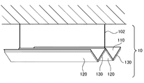
図3は、第2の実施形態に係る発光装置10の構成を示す斜視図である。図4は、本実施形態における基材110及び発光部100の断面図である。本実施形態に係る発光装置10は、以下の点を除いて第1の実施形態に係る発光装置10と同様の構成である。
(Second Embodiment)
FIG. 3 is a perspective view showing a configuration of the
まず、基材110は平板状である。そして、図3に示すように、基材110のうち固定部材102が保持されていない面には、少なくとも一つの発光部100が保持されている。図3に示す例では、基材110には複数の発光部100がマトリクス状に配置されている。
First, the
図4に示すように、発光部100には、第1光源120(第1面光源)及び第2光源130(第2面光源)を有している。第1光源120及び第2光源130は、いずれも有機ELパネルなどの面光源である。そして、第1光源120は、連結部150により、第2光源130に対して回転可能に連結されている。連結部150はたとえばヒンジ機構であり、第2光源130の縁の一部(例えば一辺)を第1光源120の縁の一部(例えば一辺)に固定している。
As shown in FIG. 4, the
発光装置10は、さらに駆動部160を備えている。駆動部160は、第1光源120を第2光源130に対して回転させることにより、第1光源120の向きを変える。本図に示す例において、駆動部160は、押出部162及びスライド部164を有している。押出部162は、制御部140によって制御されている。
The
詳細には、第1光源120のうち連結部150とは逆側の縁は、連結部152によって基材110に回転可能に保持されており、第1光源120のうち連結部150とは逆側の縁も、連結部152によって基材110に回転可能に保持されている。そして、第1光源120を保持する連結部152及び第2光源130を保持する連結部152の一方は、スライド部164によって基材110にスライド可能に保持されており、また、2つの連結部152の他方は、基材110にスライドしないように保持されている。
Specifically, the edge of the first
そして、スライド部164によって保持されている連結部152は、押出部162によってスライドされる。連結部152が他方の連結部152に対して最も離れている場合、第1光源120及び第2光源130は基材110に対してほぼ平行になっている。そして連結部152が他方の連結部152に近づくと、連結部150が基材110とは逆側に押し出され、これに伴って第1光源120及び第2光源130の向きが変わる。制御部140は、押出部162の位置を制御することにより、第1光源120及び第2光源130の向きを制御している。
Then, the connecting
具体的には、制御部140は、第1モードにおいて、押出部162を制御することにより、第1光源120に対する第2光源130の角度を基準値以上(好ましくは180°)にし、かつ第1光源120及び第2光源130を発光させる。これにより、発光部100の照射面積は広くなる。
Specifically, in the first mode, the
一方、制御部140は、第2モードにおいて、押出部162を制御することにより、第1光源120に対する第2光源130の角度を基準値未満(例えば90°未満)にし、かつ第1光源120を発光させて第2光源130を発光させない。これにより、第2方向には、第2光源130の光が照射されないことに加え、第1光源120からの光も届きにくくなる。
On the other hand, in the second mode, the
なお、駆動部160の構成は、上記した例に限定されない。
Note that the configuration of the
本実施形態によっても、発光部100を用いて広い範囲を照らしたい場合には発光部100を第1モードで発光させればよく、また、第2方向に光を照射したくない場合には、第2モードで光を照射すればよい。従って、あるタイミングでは広い範囲を照明し、かつ他のタイミングでは特定の領域を除いて照明することができる。
Also according to the present embodiment, when it is desired to illuminate a wide range using the
以上、図面を参照して実施形態及び実施例について述べたが、これらは本発明の例示であり、上記以外の様々な構成を採用することもできる。 As mentioned above, although embodiment and the Example were described with reference to drawings, these are illustrations of this invention and can also employ | adopt various structures other than the above.
10 発光装置
100 発光部
110 基材
120 第1光源
130 第2光源
140 制御部
150 連結部
160 駆動部
DESCRIPTION OF
Claims (6)
前記発光部を複数の発光モードのいずれかで発光させる制御部と、
を備える発光装置であって、
前記複数の発光モードは、第1方向及び該第1方向と異なる第2方向に光を照射する第1モードと、前記第1方向に光を照射して前記第2方向に光を照射しない第2モードを含み、
前記発光部は、
前記第1方向を向いている第1光源と、
前記第2方向を向いている第2光源と、
を備え、
前記制御部は、前記第1モードでは前記第1光源及び前記第2光源を発光させ、前記第2モードでは前記第1光源を発光させ、
前記第1方向は前記発光装置から画像表示面の観察者に向かう方向であり、
前記第2方向は前記発光装置から前記画像表示面に向かう方向である発光装置。 A light emitting unit;
A control unit that causes the light emitting unit to emit light in any of a plurality of light emitting modes;
A light emitting device Ru provided with,
The plurality of emission modes include a first mode in which light is emitted in a first direction and a second direction different from the first direction, and a first mode in which light is emitted in the first direction and no light is emitted in the second direction. 2 mode only contains,
The light emitting unit
A first light source facing the first direction;
A second light source facing the second direction;
With
The control unit causes the first light source and the second light source to emit light in the first mode, causes the first light source to emit light in the second mode,
The first direction is a direction from the light emitting device toward an observer of the image display surface,
The light emitting device, wherein the second direction is a direction from the light emitting device toward the image display surface .
前記制御部は、前記画像表示面に画像が表示されているときは前記第2モードを選択し、前記画像表示面に画像が表示されていないときは前記第1モードを選択する発光装置。 The light-emitting device according to claim 1 .
The control unit is a light-emitting device that selects the second mode when an image is displayed on the image display surface, and selects the first mode when an image is not displayed on the image display surface.
前記発光部を複数の発光モードのいずれかで発光させる制御部と、
を備える発光装置であって、
前記複数の発光モードは、第1方向及び該第1方向と異なる第2方向に光を照射する第1モードと、前記第1方向に光を照射して前記第2方向に光を照射しない第2モードを含み、
前記発光部は、
前記第1方向を向いている第1光源と、
前記第2方向を向いている第2光源と、
を備え、
前記制御部は、前記第1モードでは前記第1光源及び前記第2光源を発光させ、前記第2モードでは前記第1光源を発光させ、
前記第1方向は発光装置から窓の観察者に向かう方向であり、
前記第2方向は発光装置から前記窓に向かう方向である発光装置。 A light emitting unit;
A control unit that causes the light emitting unit to emit light in any of a plurality of light emitting modes;
A light emitting device comprising:
The plurality of emission modes include a first mode in which light is emitted in a first direction and a second direction different from the first direction, and a first mode in which light is emitted in the first direction and no light is emitted in the second direction. Including 2 modes,
The light emitting unit
A first light source facing the first direction;
A second light source facing the second direction;
With
The control unit causes the first light source and the second light source to emit light in the first mode, causes the first light source to emit light in the second mode,
The first direction is a direction from the light emitting device toward the viewer of the window;
The light emitting device, wherein the second direction is a direction from the light emitting device toward the window.
前記発光装置は移動体に搭載されており、
前記窓は、前記移動体に設けられており
前記制御部は、前記移動体が移動しているときには前記第2モードを選択し、前記移動体が停止しているときは前記第1モードを選択する発光装置。 The light emitting device according to claim 3 .
The light emitting device is mounted on a moving body,
The window is provided in the moving body, and the control unit selects the second mode when the moving body is moving, and selects the first mode when the moving body is stopped. Light-emitting device.
前記発光装置は移動体に搭載されており、
前記窓は、前記移動体に設けられており
前記制御部は、前記移動体の移動速度が第一の速度を超えたときには前記第2モードを選択し、前記移動速度が前記第一の速度以下の場合には前記第1モードを選択する発光装置。 The light emitting device according to claim 3 .
The light emitting device is mounted on a moving body,
The window is provided in the moving body, and the control unit selects the second mode when the moving speed of the moving body exceeds a first speed, and the moving speed is equal to or lower than the first speed. In the case of, a light emitting device for selecting the first mode.
第2面光源と、
前記第1面光源を前記第2面光源に対して回転可能に連結する連結部と、
前記第1面光源を前記第2面光源に対して回転させる駆動部と、
前記第1面光源、前記第2面光源、及び前記駆動部を制御する制御部と、
を備える発光装置であって、
前記発光装置は、複数の発光モードで発光し、
前記制御部は、
第1の前記発光モードにおいて、前記駆動部を制御することにより前記第1面光源に対する前記第2面光源の角度を基準値以上にし、かつ前記第1面光源及び前記第2面光源を発光させ、
第2の前記発光モードにおいて、前記駆動部を制御することにより前記第1面光源に対する前記第2面光源の角度を前記基準値未満にし、かつ前記第1面光源を発光させて前記第2面光源を発光させない発光装置。 A first surface light source;
A second surface light source;
A connecting portion for rotatably connecting the first surface light source with respect to the second surface light source,
A driving unit for rotating the first surface light source with respect to the second surface light source,
A controller that controls the first surface light source, the second surface light source, and the drive unit;
A light emitting device Ru provided with,
The light emitting device emits light in a plurality of light emission modes,
The controller is
In the first light emission mode, the angle of the second surface light source with respect to the first surface light source is set to a reference value or more by controlling the drive unit, and the first surface light source and the second surface light source are caused to emit light. ,
In the second light emission mode, by controlling the drive unit, the angle of the second surface light source with respect to the first surface light source is made less than the reference value, and the first surface light source is caused to emit light to cause the second surface to emit light. A light- emitting device that does not emit light.
Priority Applications (1)
| Application Number | Priority Date | Filing Date | Title |
|---|---|---|---|
| JP2014133261A JP6416514B2 (en) | 2014-06-27 | 2014-06-27 | Light emitting device |
Applications Claiming Priority (1)
| Application Number | Priority Date | Filing Date | Title |
|---|---|---|---|
| JP2014133261A JP6416514B2 (en) | 2014-06-27 | 2014-06-27 | Light emitting device |
Related Child Applications (1)
| Application Number | Title | Priority Date | Filing Date |
|---|---|---|---|
| JP2018189428A Division JP2019021637A (en) | 2018-10-04 | 2018-10-04 | Light-emitting device |
Publications (3)
| Publication Number | Publication Date |
|---|---|
| JP2016012462A JP2016012462A (en) | 2016-01-21 |
| JP2016012462A5 JP2016012462A5 (en) | 2017-06-22 |
| JP6416514B2 true JP6416514B2 (en) | 2018-10-31 |
Family
ID=55229059
Family Applications (1)
| Application Number | Title | Priority Date | Filing Date |
|---|---|---|---|
| JP2014133261A Active JP6416514B2 (en) | 2014-06-27 | 2014-06-27 | Light emitting device |
Country Status (1)
| Country | Link |
|---|---|
| JP (1) | JP6416514B2 (en) |
Family Cites Families (6)
| Publication number | Priority date | Publication date | Assignee | Title |
|---|---|---|---|---|
| JPH03164340A (en) * | 1989-11-21 | 1991-07-16 | Narudetsuku Kk | Room lamp control device for vehicle |
| JPH09301062A (en) * | 1996-05-15 | 1997-11-25 | Nissan Diesel Motor Co Ltd | Method and device lighting interior of vehicle |
| JP2002114091A (en) * | 2000-10-11 | 2002-04-16 | Mitsubishi Cable Ind Ltd | Lighting system for vehicle cabin |
| JP2010199004A (en) * | 2009-02-27 | 2010-09-09 | Nec Lighting Ltd | Luminaire |
| JP2014078320A (en) * | 2012-10-09 | 2014-05-01 | Mitsubishi Chemicals Corp | Illuminating device |
| JP2015217763A (en) * | 2014-05-16 | 2015-12-07 | トヨタ紡織株式会社 | Vehicular lighting device |
-
2014
- 2014-06-27 JP JP2014133261A patent/JP6416514B2/en active Active
Also Published As
| Publication number | Publication date |
|---|---|
| JP2016012462A (en) | 2016-01-21 |
Similar Documents
| Publication | Publication Date | Title |
|---|---|---|
| US8277055B2 (en) | Multiple view display system using a single projector and method of operating the same | |
| JP2017072668A5 (en) | ||
| JP2018160469A (en) | Luminaire | |
| JP2013538305A5 (en) | ||
| TW200912115A (en) | A cover for a light source | |
| WO2014171060A1 (en) | Head-up display device | |
| JP2019012483A5 (en) | ||
| EP3469255B1 (en) | Lighting device | |
| US20150176788A1 (en) | Stage representation device and stage representation method | |
| EP3187775B1 (en) | Lamp device for vehicle | |
| WO2017056147A1 (en) | Illumination device | |
| JP6557354B2 (en) | Lighting device | |
| JP6065697B2 (en) | VEHICLE LIGHTING DEVICE AND VEHICLE LIGHTING SYSTEM | |
| JP6416514B2 (en) | Light emitting device | |
| JP2019021637A (en) | Light-emitting device | |
| JP2008134423A (en) | Display apparatus | |
| JP6782454B2 (en) | Aerial display device and building materials | |
| US20160174337A1 (en) | Luminaire system having touch input for control of light output angle | |
| JP2018028965A (en) | Lightening system | |
| JP2020015412A5 (en) | ||
| JP2018028560A (en) | Illumination device | |
| JP6306290B2 (en) | Lighting device | |
| JP2015205647A (en) | On-vehicle led lamp | |
| JP2021189302A (en) | Display device | |
| JP6382010B2 (en) | Bezel member, bezel body, and display device for vehicle |
Legal Events
| Date | Code | Title | Description |
|---|---|---|---|
| A521 | Written amendment |
Free format text: JAPANESE INTERMEDIATE CODE: A523 Effective date: 20170510 |
|
| A621 | Written request for application examination |
Free format text: JAPANESE INTERMEDIATE CODE: A621 Effective date: 20170510 |
|
| A977 | Report on retrieval |
Free format text: JAPANESE INTERMEDIATE CODE: A971007 Effective date: 20180216 |
|
| A131 | Notification of reasons for refusal |
Free format text: JAPANESE INTERMEDIATE CODE: A131 Effective date: 20180227 |
|
| A521 | Written amendment |
Free format text: JAPANESE INTERMEDIATE CODE: A523 Effective date: 20180418 |
|
| TRDD | Decision of grant or rejection written | ||
| A01 | Written decision to grant a patent or to grant a registration (utility model) |
Free format text: JAPANESE INTERMEDIATE CODE: A01 Effective date: 20180911 |
|
| A61 | First payment of annual fees (during grant procedure) |
Free format text: JAPANESE INTERMEDIATE CODE: A61 Effective date: 20181004 |
|
| R150 | Certificate of patent or registration of utility model |
Ref document number: 6416514 Country of ref document: JP Free format text: JAPANESE INTERMEDIATE CODE: R150 |