JP6416377B2 - Vent cap assembly - Google Patents
Vent cap assembly Download PDFInfo
- Publication number
- JP6416377B2 JP6416377B2 JP2017505804A JP2017505804A JP6416377B2 JP 6416377 B2 JP6416377 B2 JP 6416377B2 JP 2017505804 A JP2017505804 A JP 2017505804A JP 2017505804 A JP2017505804 A JP 2017505804A JP 6416377 B2 JP6416377 B2 JP 6416377B2
- Authority
- JP
- Japan
- Prior art keywords
- vent
- protrusion
- cap
- outer skirt
- notch
- Prior art date
- Legal status (The legal status is an assumption and is not a legal conclusion. Google has not performed a legal analysis and makes no representation as to the accuracy of the status listed.)
- Expired - Fee Related
Links
- 239000007788 liquid Substances 0.000 claims description 47
- 238000009423 ventilation Methods 0.000 claims description 21
- 238000004891 communication Methods 0.000 claims description 10
- 239000012530 fluid Substances 0.000 claims description 10
- 230000008878 coupling Effects 0.000 claims description 2
- 238000010168 coupling process Methods 0.000 claims description 2
- 238000005859 coupling reaction Methods 0.000 claims description 2
- 235000008429 bread Nutrition 0.000 claims 1
- MHAJPDPJQMAIIY-UHFFFAOYSA-N Hydrogen peroxide Chemical compound OO MHAJPDPJQMAIIY-UHFFFAOYSA-N 0.000 description 34
- 239000007789 gas Substances 0.000 description 32
- 238000012360 testing method Methods 0.000 description 19
- 210000003128 head Anatomy 0.000 description 15
- 239000000203 mixture Substances 0.000 description 13
- 238000002591 computed tomography Methods 0.000 description 6
- 238000011056 performance test Methods 0.000 description 6
- 230000008901 benefit Effects 0.000 description 5
- 239000004698 Polyethylene Substances 0.000 description 4
- 238000009825 accumulation Methods 0.000 description 4
- 238000000354 decomposition reaction Methods 0.000 description 4
- 230000005484 gravity Effects 0.000 description 4
- 229920000573 polyethylene Polymers 0.000 description 4
- 230000002087 whitening effect Effects 0.000 description 4
- 239000004743 Polypropylene Substances 0.000 description 3
- 239000000853 adhesive Substances 0.000 description 3
- 230000001070 adhesive effect Effects 0.000 description 3
- 210000000214 mouth Anatomy 0.000 description 3
- -1 polypropylene Polymers 0.000 description 3
- 229920001155 polypropylene Polymers 0.000 description 3
- 241000628997 Flos Species 0.000 description 2
- 230000000712 assembly Effects 0.000 description 2
- 238000000429 assembly Methods 0.000 description 2
- QVGXLLKOCUKJST-UHFFFAOYSA-N atomic oxygen Chemical compound [O] QVGXLLKOCUKJST-UHFFFAOYSA-N 0.000 description 2
- 239000000499 gel Substances 0.000 description 2
- 238000000034 method Methods 0.000 description 2
- 238000012986 modification Methods 0.000 description 2
- 230000004048 modification Effects 0.000 description 2
- 239000001301 oxygen Substances 0.000 description 2
- 229910052760 oxygen Inorganic materials 0.000 description 2
- 230000002093 peripheral effect Effects 0.000 description 2
- 239000005020 polyethylene terephthalate Substances 0.000 description 2
- 229920000139 polyethylene terephthalate Polymers 0.000 description 2
- XLYOFNOQVPJJNP-UHFFFAOYSA-N water Substances O XLYOFNOQVPJJNP-UHFFFAOYSA-N 0.000 description 2
- 206010006326 Breath odour Diseases 0.000 description 1
- 241000195940 Bryophyta Species 0.000 description 1
- 229920000219 Ethylene vinyl alcohol Polymers 0.000 description 1
- 206010020675 Hypermetropia Diseases 0.000 description 1
- 206010020751 Hypersensitivity Diseases 0.000 description 1
- 208000026935 allergic disease Diseases 0.000 description 1
- 201000009310 astigmatism Diseases 0.000 description 1
- 230000004888 barrier function Effects 0.000 description 1
- 239000003795 chemical substances by application Substances 0.000 description 1
- 239000007910 chewable tablet Substances 0.000 description 1
- 229940112822 chewing gum Drugs 0.000 description 1
- 235000015218 chewing gum Nutrition 0.000 description 1
- 238000000576 coating method Methods 0.000 description 1
- 238000010276 construction Methods 0.000 description 1
- 238000011109 contamination Methods 0.000 description 1
- 229920001577 copolymer Polymers 0.000 description 1
- 239000002537 cosmetic Substances 0.000 description 1
- 208000002925 dental caries Diseases 0.000 description 1
- 239000000551 dentifrice Substances 0.000 description 1
- 239000002781 deodorant agent Substances 0.000 description 1
- 239000003814 drug Substances 0.000 description 1
- 239000004715 ethylene vinyl alcohol Substances 0.000 description 1
- 230000004438 eyesight Effects 0.000 description 1
- 239000006260 foam Substances 0.000 description 1
- 208000007565 gingivitis Diseases 0.000 description 1
- RZXDTJIXPSCHCI-UHFFFAOYSA-N hexa-1,5-diene-2,5-diol Chemical compound OC(=C)CCC(O)=C RZXDTJIXPSCHCI-UHFFFAOYSA-N 0.000 description 1
- 230000004305 hyperopia Effects 0.000 description 1
- 201000006318 hyperopia Diseases 0.000 description 1
- 230000009610 hypersensitivity Effects 0.000 description 1
- 238000005286 illumination Methods 0.000 description 1
- 239000004615 ingredient Substances 0.000 description 1
- 238000001746 injection moulding Methods 0.000 description 1
- 230000007774 longterm Effects 0.000 description 1
- 239000007937 lozenge Substances 0.000 description 1
- 238000004519 manufacturing process Methods 0.000 description 1
- 239000000463 material Substances 0.000 description 1
- 235000011929 mousse Nutrition 0.000 description 1
- 239000002324 mouth wash Substances 0.000 description 1
- 208000001491 myopia Diseases 0.000 description 1
- 230000004379 myopia Effects 0.000 description 1
- 201000001245 periodontitis Diseases 0.000 description 1
- 150000002978 peroxides Chemical class 0.000 description 1
- 239000004033 plastic Substances 0.000 description 1
- 229920003023 plastic Polymers 0.000 description 1
- 239000004417 polycarbonate Substances 0.000 description 1
- 229920000515 polycarbonate Polymers 0.000 description 1
- 229920000642 polymer Polymers 0.000 description 1
- 230000008569 process Effects 0.000 description 1
- 230000000717 retained effect Effects 0.000 description 1
- 239000007921 spray Substances 0.000 description 1
- 229940124597 therapeutic agent Drugs 0.000 description 1
- 239000000606 toothpaste Substances 0.000 description 1
- 229940095688 toothpaste product Drugs 0.000 description 1
- 230000000007 visual effect Effects 0.000 description 1
- 239000011800 void material Substances 0.000 description 1
Images


Classifications
-
- B—PERFORMING OPERATIONS; TRANSPORTING
- B65—CONVEYING; PACKING; STORING; HANDLING THIN OR FILAMENTARY MATERIAL
- B65D—CONTAINERS FOR STORAGE OR TRANSPORT OF ARTICLES OR MATERIALS, e.g. BAGS, BARRELS, BOTTLES, BOXES, CANS, CARTONS, CRATES, DRUMS, JARS, TANKS, HOPPERS, FORWARDING CONTAINERS; ACCESSORIES, CLOSURES, OR FITTINGS THEREFOR; PACKAGING ELEMENTS; PACKAGES
- B65D41/00—Caps, e.g. crown caps or crown seals, i.e. members having parts arranged for engagement with the external periphery of a neck or wall defining a pouring opening or discharge aperture; Protective cap-like covers for closure members, e.g. decorative covers of metal foil or paper
- B65D41/02—Caps or cap-like covers without lines of weakness, tearing strips, tags, or like opening or removal devices
-
- B—PERFORMING OPERATIONS; TRANSPORTING
- B65—CONVEYING; PACKING; STORING; HANDLING THIN OR FILAMENTARY MATERIAL
- B65D—CONTAINERS FOR STORAGE OR TRANSPORT OF ARTICLES OR MATERIALS, e.g. BAGS, BARRELS, BOTTLES, BOXES, CANS, CARTONS, CRATES, DRUMS, JARS, TANKS, HOPPERS, FORWARDING CONTAINERS; ACCESSORIES, CLOSURES, OR FITTINGS THEREFOR; PACKAGING ELEMENTS; PACKAGES
- B65D23/00—Details of bottles or jars not otherwise provided for
- B65D23/06—Integral drip catchers or drip-preventing means
-
- B—PERFORMING OPERATIONS; TRANSPORTING
- B65—CONVEYING; PACKING; STORING; HANDLING THIN OR FILAMENTARY MATERIAL
- B65D—CONTAINERS FOR STORAGE OR TRANSPORT OF ARTICLES OR MATERIALS, e.g. BAGS, BARRELS, BOTTLES, BOXES, CANS, CARTONS, CRATES, DRUMS, JARS, TANKS, HOPPERS, FORWARDING CONTAINERS; ACCESSORIES, CLOSURES, OR FITTINGS THEREFOR; PACKAGING ELEMENTS; PACKAGES
- B65D51/00—Closures not otherwise provided for
- B65D51/16—Closures not otherwise provided for with means for venting air or gas
- B65D51/1605—Closures not otherwise provided for with means for venting air or gas whereby the interior of the container is maintained in permanent gaseous communication with the exterior
-
- B—PERFORMING OPERATIONS; TRANSPORTING
- B65—CONVEYING; PACKING; STORING; HANDLING THIN OR FILAMENTARY MATERIAL
- B65D—CONTAINERS FOR STORAGE OR TRANSPORT OF ARTICLES OR MATERIALS, e.g. BAGS, BARRELS, BOTTLES, BOXES, CANS, CARTONS, CRATES, DRUMS, JARS, TANKS, HOPPERS, FORWARDING CONTAINERS; ACCESSORIES, CLOSURES, OR FITTINGS THEREFOR; PACKAGING ELEMENTS; PACKAGES
- B65D51/00—Closures not otherwise provided for
- B65D51/24—Closures not otherwise provided for combined or co-operating with auxiliary devices for non-closing purposes
Description
本発明は、通気キャップアセンブリに関する。より詳細には、本発明は、気体が大気に逃げるのを可能にしながら、収容容器からの液体のオーバフロー及び蓄積を可能にする通気キャップに関する。 The present invention relates to a vent cap assembly. More particularly, the present invention relates to a vent cap that allows liquid to overflow and accumulate from a receiving container while allowing gas to escape to the atmosphere.
過酸化物は、歯のホワイトニングのような口腔美容上の目的で、並びに歯肉炎、過敏症、虫歯、及び歯周炎の治療のために有効であることが証明されている。過酸化水素は広く知られており、歯のホワイトニング効果のためにストリップの中で使用されている。しかしながら、他の成分との相溶性の悪さや長期保管安定性の低さの問題が、過酸化水素を他の口腔ケア組成物中で、特に練り歯磨き及びジェルにおいて使用することを難しくさせている。 Peroxides have proven effective for oral cosmetic purposes such as tooth whitening and for the treatment of gingivitis, hypersensitivity, caries and periodontitis. Hydrogen peroxide is widely known and is used in strips for tooth whitening effects. However, problems with poor compatibility with other ingredients and low long-term storage stability make it difficult to use hydrogen peroxide in other oral care compositions, especially in toothpastes and gels. .
過酸化水素は容易に分解して経時的に水及び酸素を生じること、及び温度の上昇がこの分解を促進することは周知である。口腔ケア製品は、製造後、熱い倉庫の中又は商品棚の上に置かれる場合が多く、その間に気体が発生する可能性がある。分解中に発生した気体により、たとえ組成物が含有している過酸化水素の濃度が比較的低い場合であっても、過酸化水素を収容しているチューブの膨張及び破裂が生じる場合がある。チューブ内で発生する気体を放出させる必要があるにもかかわらず、口腔ケア製品用の現行キャップには通気孔が付いていない。 It is well known that hydrogen peroxide decomposes easily to produce water and oxygen over time, and that increasing the temperature promotes this decomposition. Oral care products are often placed after production in hot warehouses or on product shelves, during which gas can evolve. The gas generated during decomposition may cause expansion and rupture of the tube containing the hydrogen peroxide, even when the concentration of hydrogen peroxide contained in the composition is relatively low. Despite the need to release the gas generated in the tube, current caps for oral care products are not vented.
保管中に不必要に高い内部圧力が蓄積されることにより漏れが生じて、製品がチューブ及びキャップの両方の外面に着いた状態となる場合がある。更に、保管中にチューブが破裂しなかったとしても、内部圧力により、消費者がチューブを初めて開けたときに自動分注されてしまう場合がある。製品が自動分注されると、製品が制御不能な状態であふれ出て、消費者に混乱を招き、かつ製品の損失を引き起こす。多くの消費者は、過酸化水素がもたらす口腔ケア効果を好むが、口腔ケア組成物の新しい箱を開けてチューブが漏れている又は破裂しているのを見出すことを快く思わない。消費者は、チューブの漏れにより手やカウンターが汚れたと苦情を言う。 Unnecessarily high internal pressure builds up during storage, causing leakage and leaving the product on the outer surface of both the tube and cap. Furthermore, even if the tube does not rupture during storage, the internal pressure may cause automatic dispensing when the consumer opens the tube for the first time. When a product is dispensed automatically, the product overflows out of control, causing confusion to the consumer and causing product loss. Many consumers prefer the oral care benefits that hydrogen peroxide provides, but are not willing to open a new box of oral care compositions and find that the tube is leaking or rupturing. Consumers complain that hands and counters have become dirty due to tube leaks.
したがって、気体をチューブから放出させると同時にあふれ出た製品を捕捉することが
できる、改善されたキャップが求められている。
Therefore, there is a need for an improved cap that can release gas from the tube and at the same time capture the overflowing product.
本明細書には、長手方向軸線を有する通気キャップであって、(1)インサートであって、(a)フロアパンと、(b)前記フロアパンに結合された突起部近位端から、前記突起部近位端から長手方向遠方の突起部遠位端まで延在する突起部と、を含み、前記突起部が前記突起部を貫通する突起部開口部を画定する、インサートと、(2)シェルであって、(a)前記フロアパンに結合されかつ前記フロアパンから長手方向に外側に延在する外側スカートと、(b)前記外側スカートに結合された上部と、を含み、前記上部及び前記外側スカートが前記フロアパンと前記上部との間にヘッドスペースを画定し、前記突起部が前記ヘッドスペースの一部分内まで延在する、シェルと、(3)前記ヘッドスペースと大気との間を流体連通する通気孔と、を備える、通気キャップが記載される。 The present specification includes a ventilation cap having a longitudinal axis, wherein: (1) an insert, (a) a floor pan; and (b) a protrusion proximal end coupled to the floor pan, A protrusion extending from a proximal end of the protrusion to a distal distal end of the protrusion in a longitudinal direction, wherein the protrusion defines a protrusion opening through the protrusion; and (2) A shell comprising: (a) an outer skirt coupled to the floor pan and extending longitudinally outwardly from the floor pan; and (b) an upper portion coupled to the outer skirt; The outer skirt defines a head space between the floor pan and the upper portion, and the protrusion extends into a portion of the head space; and (3) between the head space and the atmosphere. Ventilation in fluid communication Comprises, when, as described vent cap.
本明細書には、更に、長手方向軸線を有する通気キャップであって、(1)インサートであって、(a)フロアパンと、(b)前記フロアパンに結合された壁近位端から、前記壁近位端から長手方向遠方の壁遠位端まで延在する内側保持壁と、(c)前記フロアパンに結合された突起部近位端から、突起部近位端から長手方向遠方の突起部遠位端まで延在する突起部と、を含み、前記突起部が前記突起部を貫通する突起部開口部を画定する、インサートと、(2)シェルであって、(a)前記フロアパンに結合されかつ前記フロアパンから長手方向に外側に延在する外側スカートと、(b)前記外側スカートに結合された上部と、を含み、前記上部及び前記外側スカートが前記フロアパンと前記上部との間にヘッドスペースを画定し、前記突起部が前記ヘッドスペースの一部分内まで延在する、シェルと、前記外側スカート及び前記内側保持壁がそれらの間にチャネルを画定する、シェルと、(3)通気キャップを外部収容容器に結合させるための取付部材と、(4)前記ヘッドスペースと前記チャネルとの間を流体連通する通気孔と、(5)前記チャネルと大気との間を流体連通する切欠き部と、備える、通気キャップが記載される。 The specification further includes a vent cap having a longitudinal axis, comprising: (1) an insert comprising (a) a floor pan; and (b) a wall proximal end coupled to the floor pan. An inner retaining wall extending from the proximal wall end to the distal wall distally longitudinally; (c) from the proximal proximal end coupled to the floor pan; A protrusion extending to the distal end of the protrusion, the protrusion defining a protrusion opening through the protrusion, and (2) a shell, (a) the floor An outer skirt coupled to the pan and extending longitudinally outwardly from the floor pan; and (b) an upper portion coupled to the outer skirt, wherein the upper portion and the outer skirt are the floor pan and the upper portion A head space between the A shell that extends into a portion of the headspace, a shell between which the outer skirt and the inner retaining wall define a channel, and (3) for coupling the vent cap to the outer container A ventilation cap comprising: (4) a vent hole that fluidly communicates between the head space and the channel; and (5) a notch that fluidly communicates between the channel and the atmosphere. Is done.
本明細書には、更に、通気キャップアセンブリであって、(1)収容容器開口部が貫通しているノズルを含む収容容器と、(2)ノズルの上に位置付けられるように構成されている通気キャップであって、(a)インサートであって、
(i)フロアパンと、(ii)前記フロアパンに結合された壁近位端から、前記壁近位端から長手方向遠方の壁遠位端まで延在する内側保持壁と、(iii)前記フロアパンに結合された突起部近位端から、前記突起部近位端から長手方向遠方の突起部遠位端まで延在する突起部と、を含み、
前記突起部遠位端が前記突起部遠位端を貫通する突起部開口部を画定し、前記突起部開口部は、前記突起部が前記ノズルの上に位置付けられた際に、前記収容容器開口部と流体連通する、インサートと、(b)シェルであって、(i)前記フロアパンに結合されかつ前記フロアパンから長手方向に外側に延在する外側スカートと、(ii)前記外側スカートに結合された上部と、を含み、前記上部及び前記外側スカートが前記フロアパンと前記上部との間にヘッドスペースを画定し、前記内側保持壁及び前記外側スカートがそれらの間にチャネルを画定する、シェルと、(c)前記ヘッドスペースと前記チャネルとの間を流体連通する通気孔と、(d)前記チャネルと大気との間を流体連通する切欠き部と、を備える通気キャップと、を備える通気キャップアセンブリが記載される。
The present specification further includes a vent cap assembly, (1) a containment vessel including a nozzle through which the containment vessel opening extends, and (2) a vent configured to be positioned over the nozzle. A cap, (a) an insert,
(I) a floor pan; (ii) an inner retaining wall extending from a wall proximal end coupled to the floor pan to a wall distal end longitudinally far from the wall proximal end; A protrusion extending from a protrusion proximal end coupled to the floor pan to a protrusion distal end longitudinally far from the protrusion proximal end,
The protrusion distal end defines a protrusion opening that penetrates the protrusion distal end, and the protrusion opening is open when the protrusion is positioned over the nozzle. An insert in fluid communication with the section; (b) a shell; (i) an outer skirt coupled to the floor pan and extending longitudinally outward from the floor pan; and (ii) the outer skirt. A combined upper portion, wherein the upper portion and the outer skirt define a headspace between the floor pan and the upper portion, and the inner retaining wall and the outer skirt define a channel therebetween. A vent cap comprising: a shell; (c) a vent hole that fluidly communicates between the head space and the channel; and (d) a notch that fluidly communicates between the channel and the atmosphere. Vent cap assembly is described.
本明細書は、本発明を詳細に指摘し明確に特許請求する請求項をもって結論とするが、本発明は、添付の図面と併せてなされる以下の説明から、より一層よく理解されると考える。
過酸化水素は、口腔ケア組成物中で使用するのに有効な歯のホワイトニング剤である。しかしながら、過酸化水素が容易に分解して水と酸素を形成することは知られている。過酸化水素の分解中に発生する気体は、低濃度の過酸化水素を含有する口腔ケア製品のチューブを膨張させて破裂させる。通気孔のないキャップを備えたチューブ内で気体が発生した結果、製品の漏れ及び自動分注が生じて、消費者が容認できない汚れを生じ、かつ製品の損失を引き起こす可能性がある。 Hydrogen peroxide is an effective tooth whitening agent for use in oral care compositions. However, it is known that hydrogen peroxide readily decomposes to form water and oxygen. The gas generated during the decomposition of hydrogen peroxide causes the tube of the oral care product containing a low concentration of hydrogen peroxide to expand and rupture. As a result of the generation of gas in a tube with a cap without vents, product leakage and automatic dispensing can occur, resulting in unacceptable soiling for the consumer and loss of product.
しかしながら、通気キャップを使用して収容容器から気体を放出させ、漏れ及び自動分注を防止できることが見出された。本発明は、消費者に見えることなく、収容容器からの液体のオーバフロー及び蓄積並びに気体の大気への放出を可能にするヘッドスペースを有することができる通気キャップアセンブリを目的とする。本明細書に開示される試験中、40℃、相対湿度(RH)75%で90日後に、過酸化水素を有する口腔ケア組成物を収容している通気キャップアセンブリからの漏れは、視認できなかった。これとは反対に、40℃、相対湿度(RH)75%で90日後に、過酸化水素を有する口腔ケア組成物を収容している通気孔のない対照キャップアセンブリからの漏れは、視認可能であった。 However, it has been found that a vent cap can be used to release gas from the containment vessel to prevent leakage and automatic dispensing. The present invention is directed to a vent cap assembly that can have a headspace that allows the overflow and accumulation of liquid from a containment vessel and the release of gas to the atmosphere without being visible to the consumer. During the tests disclosed herein, after 90 days at 40 ° C. and 75% relative humidity (RH), leaks from the vent cap assembly containing the oral care composition with hydrogen peroxide are not visible. It was. In contrast, after 90 days at 40 ° C. and 75% relative humidity (RH), leakage from a non-vented control cap assembly containing an oral care composition with hydrogen peroxide is visible. there were.
本発明の通気キャップは、収容容器からオーバフローした液体がキャップのヘッドスペース内に閉じ込められたままとなり、収容容器内に逆流することがないように適合され得る。ヘッドスペース内の液体は、収容容器から大気までの流路が塞がれない」というような方法で蓄積されることができる。インサートとシェルが結合されると、発生した気体の流路が形成され得、この流路は収容容器からヘッドスペースまで延在し、チャネルを通って大気まで延長される。インサートとシェルが結合されると気体の流路が形成され得るが、流路を形成するための特別な方法でインサートとシェルを整列させる必要はない場合がある。 The vent cap of the present invention can be adapted so that liquid overflowing from the receiving container remains confined in the cap headspace and does not flow back into the receiving container. The liquid in the head space can be accumulated in such a way that the flow path from the storage container to the atmosphere is not blocked. When the insert and shell are combined, a flow path for the generated gas can be formed, which extends from the receiving container to the headspace and through the channel to the atmosphere. When the insert and shell are combined, a gas flow path may be formed, but it may not be necessary to align the insert and shell in a special way to form the flow path.
長手方向の突起部がフロアパンから延びていてもよく、ヘッドスペースの一部内に配設されてもよい。更に、突起部は、ノズルの上に位置付けられ、かつノズルを密閉するように適合されてもよい。そのような構成では、圧力が液体を収容容器からオーバフローさせたときに、液体は収容容器の開口部を通って移動し、突起部開口部を直接通って進み続けて、キャップのヘッドスペースに入る。 Longitudinal protrusions may extend from the floor pan and may be disposed within a portion of the headspace. Further, the protrusion may be positioned over the nozzle and adapted to seal the nozzle. In such a configuration, when pressure causes the liquid to overflow from the receiving container, the liquid moves through the opening in the receiving container and continues directly through the protrusion opening to enter the cap headspace. .
本明細書で使用するとき、「結合される」とは、「永久的に結合される」又は「取り外し可能に結合される」ことを意味する。「永久的に結合される」という用語は、第1の要素と第2の要素とがそれら要素の一方又は両方を少なくとも部分的に破壊することなく互いに分離されることができないように、第1の要素が第2の要素に固定される構成を指す。「取り外し可能に結合される」という用語は、第1の要素及び第2の要素が損傷を受けずに又は最小限の損傷で第1の要素と第2の要素を分離することができるように、第1の要素が第2の要素に固定される構成を指す。 As used herein, “coupled” means “permanently coupled” or “removably coupled”. The term “permanently coupled” refers to a first element and a second element so that they cannot be separated from each other without at least partially destroying one or both of the elements. The element is fixed to the second element. The term “removably coupled” means that the first element and the second element can be separated without damage or with minimal damage. , Refers to a configuration in which the first element is secured to the second element.
本明細書で使用するとき、「口腔ケア組成物」とは、通常の使用過程において、特定の治療剤を全身投与する目的で意図的に嚥下されるものではなく、むしろ、歯の表面又は口腔組織と接触させるのに十分な時間にわたって口腔内に保持される製品を指すものと理解される。口腔ケア組成物の例としては、歯磨剤、洗口液、ムース、フォーム、マウススプレー、トローチ剤、チュアブル錠、チューインガム、歯科用ホワイトニングストリップ、フロス及びフロスコーティング、口臭消臭溶解性ストリップ、又は義歯ケア若しくは接着製品が挙げられる。口腔ケア組成物はまた、口腔表面への直接的な適用又は付着のためのストリップ又はフィルム上に組み込まれてもよい。 As used herein, an “oral care composition” is not intended to be swallowed for the purpose of systemically administering a particular therapeutic agent in the course of normal use, but rather is the surface of the tooth or the oral cavity. It is understood to refer to a product that is retained in the oral cavity for a time sufficient to contact the tissue. Examples of oral care compositions include dentifrices, mouthwashes, mousses, foams, mouth sprays, lozenges, chewable tablets, chewing gum, dental whitening strips, floss and floss coatings, bad breath deodorant soluble strips, or dentures Examples include care or adhesive products. The oral care composition may also be incorporated on a strip or film for direct application or attachment to the oral surface.
本明細書で使用するとき、「視認可能」とは、標準的な100ワットの白熱電球の照度に少なくとも相当する照明の下で、1メートルの距離から、ヒトの観察者が、肉眼(近視、遠視、若しくは乱視を補正するように適合された標準的な矯正レンズ、又は他の矯正視力を例外とする)によって、収容容器又はキャップの外面の液体の漏れを視覚的に識別できることを意味する。 As used herein, “visible” means that a human observer can see the human eye (myopia, from a distance of 1 meter under illumination equivalent to the illuminance of a standard 100 watt incandescent bulb. By means of a standard corrective lens adapted to correct for hyperopia or astigmatism (with the exception of other corrective vision), it means that liquid leakage on the outer surface of the container or cap can be visually identified.
本明細書で使用するとき、用語「含有する(include、includes、及びincluding)」は非限定的なものであることを意味し、それぞれ「含む(comprise、comprises、及びcomprising)」を意味するものと理解される。 As used herein, the terms “include”, “includes”, and “including” are meant to be non-limiting, and each means “comprise”, “comprises”, and “comprising”. It is understood.
図1は、本発明の通気キャップアセンブリ1の実施例を示す。図1の通気キャップアセンブリ1は、より詳細には、収容容器10と、収容容器10に取り付けられた通気キャップ30とを含む。図2を参照すると、収容容器10はノズル15を含むことができ、このノズル15は、収容容器10から長手方向に延出し、ノズル15を貫通する収容容器開口部20を画定している。一実施例では、通気キャップアセンブリは、収容容器10が通気キャップ30の下方に位置するように直立配置であることができる。直立配置は、ノズル15が収容容器10からの液体で詰まるのを低減することができ、かつ気体を放出することができることから望ましいことがある。別の実施例では、通気キャップアセンブリは、収容容器が通気キャップの上方に位置するように反転させた配置であってもよい。
FIG. 1 shows an embodiment of a vent cap assembly 1 of the present invention. More specifically, the ventilation cap assembly 1 of FIG. 1 includes a
更に図2を参照すると、通気キャップ30は、長手方向軸線5と、インサート35と、シェル65とを備えることができる。インサート35はシェル65に結合されることができる。一実施例では、インサート35とシェル65とは永久的に結合されてもよい。一実施例では、インサート35とシェル65とは取り外し可能に結合されてもよい。一実施例では、インサート35とシェル65は一体ものとして形成されてもよい。別の実施例では、インサート35とシェル65は2部品ものとして形成されてもよい。インサート35は、フロアパン40と内側保持壁43とを備えることができ、この内側保持壁43は、フロアパン40に結合された壁近位端45から、壁近位端45から長手方向遠方の壁遠位端47まで、長手方向に延在している。一実施例では、内側保持壁43は、フロアパン40の周縁領域を包囲することができる。一実施例では、内側保持壁は、フロアパンの周縁領域を部分的に包囲することができる。内側保持壁43は、壁近位端45を包囲するフランジ115を更に含んでもよい。更に、インサート35は突起部50を含むことができ、この突起部50は、フロアパン40に結合された突起部近位端53から、突起部近位端53から長手方向遠方の突起部遠位端55まで延在している。突起部50は、突起部50を貫通する突起部開口部60を画定することができる。一実施例では、突起部遠位端55は突起部開口部60を画定することができる。突起部50は、通気キャップ30が収容容器10に取り付けられたときにノズル15の上に位置付けられてノズル15を密閉するように構成され得る。一実施例では、突起部50がノズル15の上に位置付けられると、突起部開口部60は収容容器開口部20と流体連通することができる。シェル65は、フロアパン40に結合されかつフロアパン40からから長手方向に外側に延在する外側スカート70と、外側スカート70に結合された上部85とを含むことができる。ヘッドスペース90は、上部85とフロアパン40との間に形成されることができる。より詳細には、ヘッドスペース90は、フロアパン40、インサート35の突起部50及び内側保持壁43、並びにシェル65の外側スカート70及び上部85によって密閉された空隙によって画定されることができる。一実施例では、突起部50は、ヘッドスペース90の一部内に延在していてもよい。
Still referring to FIG. 2, the
一実施例では、ヘッドスペース90の容量はノズル15の容量よりも大きくてもよい。一実施例では、ヘッドスペース90の容量は、約3,000〜約11,000立方mmであり得、別の実施例では約5,000〜約10,000立方mm、及び別の実施例では約7,000〜約9,600立方mmであり得る。一実施例では、ヘッドスペース90の容量は約9,400立方mmであり得る。一実施例では、ノズル15の容量は、約1,000〜約2,500立方mmであり得、別の実施例では約1,100〜約2,000立方mm、及び別の実施例では約1,200〜約1,500立方mmであり得る。一実施例では、ノズル15の容量は約1,280立方mmであり得る。一実施例では、ヘッドスペース90の容量とノズル15の容量との比は、約2:1〜約10:1、別の実施例では約3:1〜約9:1、及び別の実施例では約5:1〜約8:1であり得る。一実施例では、ヘッドスペース90の容量とノズル15の容量との比は、約7.3:1であり得る。
In one embodiment, the capacity of the
図3から最も良く分かるように、結合されると、内側保持壁43及び外側スカート70は、それらの間にチャネル80を画定し得る。一実施例では、内側保持壁43は、外側スカート70に結合されたときにヘッドスペースを実質的に封止するように構成され得るが、通気孔100の位置は封止されない。内側保持壁43と外側スカート70との間に通気孔100を設けることができ、この通気孔100は、ヘッドスペースとチャネル80との間を流体連通することができる。更に、内側保持壁43と外側スカート70との間に切欠き部110を設けることができ、この切欠き部110は、チャネル80と大気との間を流体連通することができる。一実施例では、内側保持壁43は、壁近位端を包囲するフランジ115を更に含んでもよい。
As best seen in FIG. 3, when joined, the
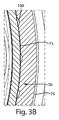
図3Aは、通気孔100の位置を更に示すための、図3における線3A−3Aに沿った断面図である。図3Aに示すように、一実施例では、内側保持壁43は通気孔100を画定してもよい。一実施例では、通気孔100は、壁遠位端に配設されてもよく、外側スカート70と結合されたときに、気体がヘッドスペースからチャネルまで移動するのを可能にすることができる。別の実施例では、図3Bに示すように、外側スカート70は、内側表面73及び外側表面75を有することができる。一実施例では、外側スカートの内側表面73は通気孔100を画定してもよい。一実施例では、外側スカートの内側表面73は、外側スカート70が内側保持壁43と接する位置において、通気孔100を画定してもよい。図3Cは、切欠き部110の位置を更に示すための、図3における線3C−3Cに沿った断面図である。図3Cに示すように、一実施例では、フランジ115は、切欠き部110を画定してもよく、外側スカート70と結合されたときに、気体がチャネルから大気まで移動するのを可能にすることができる。図3Dに示すように、一実施例では、外側スカート70は、切欠き部110を画定してもよく、フランジ115と結合されたときに、気体がチャネルから大気まで移動するのを可能にすることができる。一実施例では、外側スカートの内側表面73は切欠き部110を画定してもよい。
3A is a cross-sectional view taken along
図4A及び図4Bは、本発明を更に示すために、インサート35の斜視図を示している。図4A及び図4Bに示すように、インサート35はフロアパン40を含むことができる。図4Aに最も良く示されているように、いくつかの実施例では、インサート35は内側保持壁43を含むことができ、この内側保持壁43は、フロアパン40に結合された壁近位端45から、壁近位端45から長手方向遠方の壁遠位端47まで延在している。インサート35は突起部50を含むことができ、この突起部50は、フロアパン40に結合された突起部近位端53から、突起部近位端53から長手方向遠方の突起部遠位端55まで延在している。一実施例では、突起部50は、突起部50を貫通する突起部開口部60を画定することができる。別の実施例では、突起部遠位端55は突起部開口部60を画定する。一実施例では、内側保持壁43は、1つ又は2つ以上の小円鋸歯状部48を含んでもよい。
4A and 4B show perspective views of the
図4A、図4B、及び図4Cに示すように、いくつかの実施例では、壁遠位端47は通気孔100を画定してもよい。いくつかの実施例では、壁遠位端47は、1つの通気孔100を画定してもよいことが本明細書において理解される。いくつかの実施例では、壁遠位端47は、2つの通気孔100を画定してもよい。いくつかの実施例では、壁遠位端47は、3つの通気孔100を画定してもよい。いくつかの実施例では、壁遠位端47は、3つを超える通気孔100を画定してもよい。図4Bは、通気孔100及び切欠き部110を長手方向及び円周方向にオフセットさせることができる、インサート35の一実施例の底面図を示す。一実施例では、切欠き部110は通気孔100から、円周方向に約170度〜約190度だけ、別の実施例では約120度〜約200度だけ、別の実施例では約90度〜約270だけオフセットされてもよい。
In some embodiments, the wall distal end 47 may define a
インサート35は取付部材118を更に備えてもよく、この取付部材118は、図4Bに示すようにねじ山であってもよいが、通気キャップをノズル上に係合するための、スナップ嵌め構成などの当該技術分野において既知の任意の取付手段であってもよい。図4Cは、インサート35の内部図を示す。一実施例では、突起部の内側表面は、突起部開口部60を実質的に包囲する隆起部56を含んでもよい。一実施例では、突起部がノズルの上に位置付けられると、隆起部56は、突起部の内側表面とノズルとの間に間隙を提供することができる。
The
図5は通気キャップ30を示しており、ヘッドスペース90内に蓄積した液体120及び通気経路125が示されている。本発明の一実施例では、収容容器又は通気キャップ30からの液体120の漏れを防止しながら、気体を通気経路125に通して収容容器から大気に放出することが可能である。正常な直立配置では、ノズルは、充填手順中に残った粘稠な液体で充填され得る。収容容器内に圧力が蓄積していると、この圧力が液体120を押圧して、最初に収容容器開口部を通過させた後、突起部開口部を通過させて、ヘッドスペース90内に至らしめる。液体120はフロアパン上に蓄積し、気体が収容容器からヘッドスペース90内まで通過するのを可能にする。一実施例では、液体120の蓄積は、更なる液体120又は気体がヘッドスペース90に入るのを塞ぐことはない。一実施例では、インサート及びシェルは不透明であってもよく、液体の蓄積は消費者に見えなくてもよい。一実施例では、インサート及びシェルの色は白であり得る。
FIG. 5 shows the
気体がヘッドスペース90からチャネル80まで又はチャネル80から大気まで移動するのを可能にするために、通気孔100は、切欠き部110から長手方向にオフセットされた位置に配設されてもよい。更に、通気孔100及び切欠き部110はまた、円周方向にオフセットされることができる。理論によって制限されないが、通気孔100と切欠き部110の位置を円周方向にオフセットさせることによって、通気キャップ30からの液体120の漏れを防止することができると考えられる。そのような構成の利点の1つは、通気キャップ30内に蓄積した液体120は、ヘッドスペース90を充填し、通気孔100を介してチャネル80に入り、チャネル80の周りを円周方向に移動して、切欠き部110から出る必要があり、したがって漏れがより困難になることである。特定の実施例では、複数の通気孔100は、気体がヘッドスペース90を出る機会をより多く与える。図5に示すように、万一通気孔100が液体120で詰まった場合には、追加の通気孔100によってチャネル80への通気経路125を維持することができる。
In order to allow gas to move from the
一実施例では、通気キャップは、フロアパンと突起部とを有するインサートを含むことができる。突起部は、フロアパンに結合された突起部近位端から、突起部近位端から長手方向遠方の突起部遠位端まで延在していてもよい。通気キャップはまた、フロアパンに結合されかつフロアパンから長手方向に外側に延在する外側スカートと、外側スカートに結合される上部とを有するシェルを含むことができる。上部及び外側スカートは、フロアパンと上部との間にヘッドスペースを画定することができる。一実施例では、突起部は、ヘッドスペースの一部内に延在していてもよく、突起部は突起部開口部を画定することができる。通気キャップはまた、ヘッドスペースと大気との間を流体連通する通気孔を備えることができる。 In one example, the vent cap can include an insert having a floor pan and a protrusion. The protrusion may extend from a protrusion proximal end coupled to the floor pan to a protrusion distal end longitudinally far from the protrusion proximal end. The vent cap may also include a shell having an outer skirt coupled to the floor pan and extending longitudinally outward from the floor pan and an upper portion coupled to the outer skirt. The upper and outer skirts can define a headspace between the floor pan and the upper portion. In one example, the protrusion may extend into a portion of the headspace, and the protrusion may define a protrusion opening. The vent cap may also include a vent that provides fluid communication between the headspace and the atmosphere.
更に、通気キャップは、フロアパンに結合された壁近位端から、壁近位端から長手方向遠方の壁遠位端まで、長手方向に延在する内側保持壁を備えることができる。内側保持壁及び外側スカートは、それらの間にチャネルを画定することができる。一実施例では、内側保持壁は通気孔を画定して、気体がヘッドスペースからチャネルまで流れるのを可能にすることができる。いくつかの実施例では、通気キャップは、1つの通気孔、いくつかの実施例では2つの通気孔、いくつかの実施例では3つの通気孔を含むことができる。通気キャップは、壁近位端によって画定される切欠き部を更に備えることができる。一実施例では、切欠き部は、気体がチャネルから大気まで流れるのを可能にするように構成されることができる。いくつかの実施例では、通気キャップは、約40℃、約75%RHで約90日間の保管する間、視認可能な液体の漏れを防止することができる。 Further, the vent cap can include an inner retaining wall extending longitudinally from a wall proximal end coupled to the floor pan to a wall distal end longitudinally distal from the wall proximal end. The inner retaining wall and the outer skirt can define a channel therebetween. In one example, the inner retaining wall can define a vent to allow gas to flow from the headspace to the channel. In some examples, the vent cap may include one vent, in some examples two vents, and in some examples three vents. The vent cap can further comprise a notch defined by the proximal wall end. In one embodiment, the notch can be configured to allow gas to flow from the channel to the atmosphere. In some embodiments, the vent cap can prevent visible liquid leakage during storage for about 90 days at about 40 ° C. and about 75% RH.
一実施例では、通気キャップは、フロアパンと、内側保持壁と、突起部とを有するインサートを含むことができる。内側保持壁は、フロアパンに結合された壁近位端から、壁近位端から長手方向遠方の壁遠位端まで延在していてもよい。壁近位端はフランジによって包囲されることができる。突起部は、フロアパンに結合された突起部近位端から、突起部近位端から長手方向遠方の突起部遠位端まで延在していてもよい。一実施例では、突起部は突起部開口部を画定することができる。通気キャップはまた、フロアパンに結合されかつフロアパンから長手方向に外側に延在する外側スカートを有するシェルを含むことができる。いくつかの実施例では、内側保持壁及び外側スカートは、それらの間にチャネルを画定することができる。上部は外側スカートに結合され、かつフロアパンと上部との間にヘッドスペースを画定することができる。いくつかの実施例では、突起部は、ヘッドスペースの一部内に延在していてもよい。 In one example, the vent cap can include an insert having a floor pan, an inner retaining wall, and a protrusion. The inner retaining wall may extend from a wall proximal end coupled to the floor pan to a wall distal end longitudinally away from the wall proximal end. The proximal wall end can be surrounded by a flange. The protrusion may extend from a protrusion proximal end coupled to the floor pan to a protrusion distal end longitudinally far from the protrusion proximal end. In one example, the protrusion can define a protrusion opening. The vent cap can also include a shell coupled to the floor pan and having an outer skirt extending longitudinally outward from the floor pan. In some examples, the inner retaining wall and the outer skirt can define a channel therebetween. The upper portion is coupled to the outer skirt and a headspace can be defined between the floor pan and the upper portion. In some embodiments, the protrusion may extend within a portion of the headspace.
通気キャップはまた、ヘッドスペースとチャネルとの間を流体連通する通気孔と、チャネルと大気との間を流体連通する切欠き部とを備えることができる。いくつかの実施例では、通気キャップは、1つの通気孔、いくつかの実施例では2つの通気孔、いくつかの実施例では3つの通気孔を含むことができる。いくつかの実施例では、壁遠位端は通気孔を画定することができ、フランジは切欠き部を画定することができる。いくつかの実施例では、外側スカートの内側表面は、通気孔及び切欠き部を画定することができる。一実施例では、通気孔と切欠き部とは長手方向にオフセットされてもよい。通気孔と切欠き部とはまた、円周方向にオフセットされてもよい。 The vent cap may also include a vent hole that fluidly communicates between the headspace and the channel, and a notch that fluidly communicates between the channel and the atmosphere. In some examples, the vent cap may include one vent, in some examples two vents, and in some examples three vents. In some embodiments, the wall distal end can define a vent and the flange can define a notch. In some examples, the inner surface of the outer skirt can define a vent and a notch. In one embodiment, the vent and the notch may be offset in the longitudinal direction. The vent and the notch may also be offset in the circumferential direction.
別の実施例では、通気キャップアセンブリは、ノズルを有する収容容器と通気キャップとを有することができ、ノズルは、ノズルを貫通する収容容器開口部を有しており、通気キャップは、ノズルの上に位置付けられるように構成されている。通気キャップは、インサートと、シェルと、通気孔と、切欠き部とを備えることができる。インサートは、フロアパンと、内側保持壁と、突起部とを備えることができる。内側保持壁は、フロアパンに結合された壁近位端から、壁近位端から長手方向遠方の壁遠位端まで延在していてもよい。壁近位端はフランジによって包囲されることができる。突起部は、フロアパンに結合された突起部近位端から、突起部近位端から長手方向遠方の突起部遠位端まで延在していてもよい。一実施例では、突起部遠位端は突起部開口部を画定することができ、かつ突起部がノズルの上に位置付けられると、突起部開口部は収容容器開口部と流体連通することができる。シェルは、フロアパンに結合されかつフロアパンから長手方向に外側に延在する外側スカートと、外側スカートに結合される上部とを含むことができる。内側保持壁及び外側スカートは、それらの間にチャネルを画定することができる。上部及び外側スカートは、フロアパンと上部との間にヘッドスペースを画定することができる。いくつかの実施例では、ヘッドスペースの容量はノズルの容量よりも大きくてもよい。 In another embodiment, the vent cap assembly can include a receiving container having a nozzle and a vent cap, the nozzle having a receiving container opening extending through the nozzle, the vent cap being above the nozzle. It is comprised so that it may be positioned. The ventilation cap can include an insert, a shell, a ventilation hole, and a notch. The insert may include a floor pan, an inner holding wall, and a protrusion. The inner retaining wall may extend from a wall proximal end coupled to the floor pan to a wall distal end longitudinally away from the wall proximal end. The proximal wall end can be surrounded by a flange. The protrusion may extend from a protrusion proximal end coupled to the floor pan to a protrusion distal end longitudinally far from the protrusion proximal end. In one example, the protrusion distal end can define a protrusion opening, and when the protrusion is positioned over the nozzle, the protrusion opening can be in fluid communication with the receiving container opening. . The shell can include an outer skirt coupled to the floor pan and extending longitudinally outward from the floor pan and an upper portion coupled to the outer skirt. The inner retaining wall and the outer skirt can define a channel therebetween. The upper and outer skirts can define a headspace between the floor pan and the upper portion. In some embodiments, the headspace volume may be greater than the nozzle volume.
一実施例では、通気孔は、ヘッドスペースとチャネルとの間を流体連通することができ、切欠き部は、チャネルと大気との間を流体連通することができる。いくつかの実施例では、通気キャップは、1つの通気孔、いくつかの実施例では2つの通気孔、いくつかの実施例では3つの通気孔を含むことができる。いくつかの実施例では、内側保持壁は通気孔を画定することができ、フランジは切欠き部を画定することができる。いくつかの実施例では、外側スカートの内側表面は、通気孔及び切欠き部の両方を画定することができる。一実施例では、通気孔と切欠き部とは長手方向にオフセットされてもよい。別の実施例では、通気孔と切欠き部とは、約170〜約190度だけ円周方向にオフセットされてもよい。 In one embodiment, the vent can provide fluid communication between the headspace and the channel, and the notch can provide fluid communication between the channel and the atmosphere. In some examples, the vent cap may include one vent, in some examples two vents, and in some examples three vents. In some embodiments, the inner retaining wall can define a vent and the flange can define a notch. In some examples, the inner surface of the outer skirt can define both vents and notches. In one embodiment, the vent and the notch may be offset in the longitudinal direction. In another example, the vents and notches may be circumferentially offset by about 170 to about 190 degrees.
収容容器は、粘度が約5〜約60ブルックフィールド単位、別の実施例では約10〜約35ブルックフィールド単位、別の実施例では約15〜約18ブルックフィールド単位である液体を収容することができる。粘度は、T−E spindleを使ったブルックフィールドシンクロレクトリック粘度計のモデルRVT/2を用いて、毎分2.5回転で測定する。いくつかの実施例では、収容容器は、約0.1%〜約7%の過酸化水素、別の実施例では約0.2%〜約5%の過酸化水素、別の実施例では約1%〜約4%の過酸化水素を含む液体を収容することができる。一実施例では、液体は、約0.3%〜約3%の過酸化水素を含有することができる。一実施例では、インサート及びシェルを不透明として、ヘッドスペース内の液体が消費者に見えることを防ぐことができる。 The containment vessel may contain a liquid having a viscosity of about 5 to about 60 Brookfield units, in another embodiment about 10 to about 35 Brookfield units, and in another embodiment about 15 to about 18 Brookfield units. it can. Viscosity is measured at 2.5 revolutions per minute using a Brookfield Synchronic Viscometer model RVT / 2 using a te spindle. In some embodiments, the containment vessel is about 0.1% to about 7% hydrogen peroxide, in another embodiment about 0.2% to about 5% hydrogen peroxide, in another embodiment about A liquid containing 1% to about 4% hydrogen peroxide can be accommodated. In one example, the liquid can contain about 0.3% to about 3% hydrogen peroxide. In one embodiment, the insert and shell can be opaque to prevent the liquid in the headspace from being visible to the consumer.
一実施例では、通気キャップは、バネ又は弁などの可動部品を含まなくてもよい。そのような構造の利点の1つは、通気キャップが、収容容器と大気との間の二方向の気体運動を可能にすることができることである。 In one example, the vent cap may not include moving parts such as springs or valves. One advantage of such a structure is that the vent cap can allow bi-directional gas motion between the containment vessel and the atmosphere.
一実施例では、収容容器はヘッドスペースに流体連結され、ヘッドスペースは通気孔に流体連結され、通気孔はチャネルに流体連結され、チャネルは切欠き部に流体連結される。 In one embodiment, the receiving container is fluidly connected to the headspace, the headspace is fluidly connected to the vent, the vent is fluidly connected to the channel, and the channel is fluidly connected to the notch.
図面は通気キャップアセンブリを概略的に示しているだけであり、収容容器及び通気キャップは、様々な異なる形状、寸法、構成、及び材料で形成されてもよいことが理解されるべきである。 It should be understood that the drawings only schematically illustrate the vent cap assembly, and that the containment vessel and vent cap may be formed in a variety of different shapes, sizes, configurations, and materials.
一実施例では、通気キャップは楕円形状を有することができる。一実施例では、通気キャップは円形状を有することができる。一実施例では、外側スカートは約18mm〜約29mmの高さを有することができる。一実施例では、外側スカートは約28.9mmの高さを有することができる。一実施例では、上部は、約20mm〜約40mmの長軸及び約15mm〜約30mmの短軸を有することができる。一実施例では、上部は、約39mmの長軸及び約26.5mmの短軸を有することができる。一実施例では、インサートは、約20mm〜約40mの長軸及び約15mm〜約30mmの短軸を有することができる。一実施例では、インサートは、約36.2mmの長軸及び約18mmの短軸を有することができる。一実施例では、保持壁は約5mm〜約15mmの高さを有することができる。別の実施例では、保持壁は約8mm〜約11mmの高さを有することができる。一実施例では、突起部は、約15mm〜約21mmの高さ及び約12mm〜約18mmの直径を有することができる。一実施例では、突起部は、約19mmの高さ及び約17mmの直径を有することができる。一実施例では、チャネルは、約0.04mm〜約1.2mm、別の実施例では約0.05〜約0.09mmの幅を有することができる。一実施例では、チャネルは約0.07mmの幅を有することができる。 In one example, the vent cap can have an oval shape. In one example, the vent cap can have a circular shape. In one example, the outer skirt can have a height of about 18 mm to about 29 mm. In one example, the outer skirt can have a height of about 28.9 mm. In one example, the upper portion can have a major axis of about 20 mm to about 40 mm and a minor axis of about 15 mm to about 30 mm. In one example, the upper portion can have a major axis of about 39 mm and a minor axis of about 26.5 mm. In one example, the insert can have a major axis of about 20 mm to about 40 m and a minor axis of about 15 mm to about 30 mm. In one example, the insert may have a major axis of about 36.2 mm and a minor axis of about 18 mm. In one example, the retaining wall can have a height of about 5 mm to about 15 mm. In another example, the retaining wall can have a height of about 8 mm to about 11 mm. In one example, the protrusion can have a height of about 15 mm to about 21 mm and a diameter of about 12 mm to about 18 mm. In one example, the protrusion can have a height of about 19 mm and a diameter of about 17 mm. In one example, the channel can have a width of about 0.04 mm to about 1.2 mm, and in another example about 0.05 to about 0.09 mm. In one example, the channel can have a width of about 0.07 mm.
通気孔は、ヘッドスペースとチャネルとの間に気体を流すのを可能にするのに好適な任意の形状又は寸法とすることができる。切欠き部は、チャネルと大気との間に気体を流すのを可能にするのに好適な任意の形状又は寸法とすることができる。一実施例では、切欠き部の寸法は通気孔よりも大きくてもよい。一実施例では、切欠き部は凹形状を有してもよい。一実施例では、切欠き部は凸形状を有してもよい。一実施例では、切欠き部の深さは、約0.2mm〜約1mm、別の実施例では約0.25mm〜約0.8mm、別の実施例では約0.35mm〜約0.45mmであってもよい。一実施例では、切欠き部の深さは約0.4mmであってもよい。一実施例では、切欠き部の幅は、約0.5mm〜約2.5mm、別の実施例では約1mm〜約1.5mm、別の実施例では約1.25mm〜約2.3mmであってもよい。一実施例では、切欠き部の幅は約2mmであってもよい。一実施例では、通気孔は凹形状を有してもよい。一実施例では、通気孔は凸形状を有してもよい。一実施例では、通気孔の深さは、約0.2mm〜約0.5mm、別の実施例では約0.25mm〜約0.4mmであってもよい。一実施例では、通気孔の深さは約0.3mmであってもよい。一実施例では、通気孔の幅は、約0.5mm〜約1.5mm、別の実施例では約0.8mm〜約1.4mm、別の実施例では約0.9mm〜約1.3mmであってもよい。一実施例では、通気孔の幅は約1.21mmであってもよい。 The vent can be any shape or size suitable to allow gas to flow between the headspace and the channel. The notch can be any shape or size suitable to allow gas to flow between the channel and the atmosphere. In one embodiment, the size of the notch may be larger than the vent. In one embodiment, the notch may have a concave shape. In one embodiment, the notch may have a convex shape. In one example, the depth of the notch is about 0.2 mm to about 1 mm, in another example about 0.25 mm to about 0.8 mm, and in another example about 0.35 mm to about 0.45 mm. It may be. In one example, the depth of the notch may be about 0.4 mm. In one example, the width of the notch is about 0.5 mm to about 2.5 mm, in another example about 1 mm to about 1.5 mm, and in another example about 1.25 mm to about 2.3 mm. There may be. In one embodiment, the width of the notch may be about 2 mm. In one embodiment, the vent may have a concave shape. In one embodiment, the vent may have a convex shape. In one example, the depth of the vent may be about 0.2 mm to about 0.5 mm, and in another example about 0.25 mm to about 0.4 mm. In one example, the depth of the vent may be about 0.3 mm. In one embodiment, the vent has a width of about 0.5 mm to about 1.5 mm, in another embodiment about 0.8 mm to about 1.4 mm, and in another embodiment about 0.9 mm to about 1.3 mm. It may be. In one example, the width of the vent may be about 1.21 mm.
一実施例では、通気キャップは、ポリプロピレン(PP)、ポリカーボネート(PC)、ポリエチレンテレフタレート(PET)、ポリエチレン(PE)等などの任意の望ましいポリマー又はコポリマーから構成されてもよく、また、射出成形等などの任意の望ましいプロセスによって製造されてもよい。 In one example, the vent cap may be composed of any desired polymer or copolymer, such as polypropylene (PP), polycarbonate (PC), polyethylene terephthalate (PET), polyethylene (PE), etc., injection molding, etc. Or any other desired process.
一実施例では、収容容器は、比重が約0.7〜約2、別の実施例では約0.9〜約1.6、別の実施例では約1〜約1.4である液体を収容してもよい。一実施例では、収容容器は、比重が1を超える液体を収容してもよい。別の実施例では、収容容器は、比重が約1.45〜約1.55である液体を収容してもよい。 In one example, the containment vessel contains a liquid having a specific gravity of about 0.7 to about 2, in another example about 0.9 to about 1.6, and in another example about 1 to about 1.4. It may be accommodated. In one embodiment, the storage container may store a liquid having a specific gravity exceeding 1. In another example, the container may contain a liquid having a specific gravity of about 1.45 to about 1.55.
一実施例では、通気キャップアセンブリは、二次容器の中に直立配置で包装され得る。一実施例では、二次容器の前面は透明であってもよく、消費者が通気キャップアセンブリの一部を見ることができるようにすることができる。一実施例では、通気キャップアセンブリは、口腔ケアジェルを収容することができ、練り歯磨き製品と共に二次容器の中に包装されることができる。 In one example, the vent cap assembly can be packaged in an upright arrangement in a secondary container. In one example, the front surface of the secondary container may be transparent, allowing the consumer to see a portion of the vent cap assembly. In one example, the vent cap assembly can contain an oral care gel and can be packaged in a secondary container with a toothpaste product.
視認可能な漏れを適切に防止する通気キャップの能力を試験するために、キャップ性能試験を実施した。この実施例は、キャップ内の通気孔の存在を試験した際のキャップ性能試験の結果を示す。通気キャップの視認可能な漏れに対する性能及び堅牢性を、通気孔のない対照キャップと比較した。各試験は、過酸化水素を約3パーセント含む口腔ケア組成物を収容している収容容器を使用した。試験は、収容容器内の分解及び気体発生を促進するために、昇温条件で行われた。更に、試験は、漏れの可能性を更に加速させるために、異なる配置で設置されたキャップと収容容器のアセンブリに対して行われた。漏れは、収容容器及びキャップの外側の目視観測、及びキャップ内の漏れを評価するためのCTスキャンによって測定した。漏れは、収容容器又はキャップの外側の、ユーザーが視認可能な液体として定義された。 A cap performance test was conducted to test the ability of the vent cap to properly prevent visible leaks. This example shows the results of a cap performance test when testing for the presence of vents in the cap. The performance and robustness of the vent cap against visible leakage was compared to a control cap without vents. Each test used a receiving container containing an oral care composition containing about 3 percent hydrogen peroxide. The test was conducted under elevated temperature conditions in order to promote decomposition and gas generation in the container. In addition, tests were performed on cap and containment assemblies installed in different locations to further accelerate the potential for leakage. Leakage was measured by visual observation of the outside of the containment vessel and the cap, and a CT scan to assess leakage within the cap. Leakage was defined as a liquid visible to the user outside the containment vessel or cap.
キャップ性能試験を次のように実施した。
キャップ性能試験は、収容容器の上に位置付けられた通気キャップアセンブリ(インサート及びシェルを含む)を評価した。85mLの収容容器に、表1に示す口腔ケア組成物を68ミリリットル(2.3オンス)充填した。この実施例では、組成物の比重は約1.08、粘度は約15ブルックフィールド単位であった。収容容器は次のプラスチック及びバリアで作製された(すなわち、PE、接着剤、エチレン−ビニルアルコール、接着剤、及びPE)多層チューブであった。キャップはPPで作製した。各収容容器は、容量1,280立方mmのノズルを有した。各キャップは、9,400立方mmのヘッドスペース容量を有した。
The cap performance test was conducted as follows.
The cap performance test evaluated a vent cap assembly (including insert and shell) positioned over the containment vessel. An 85 mL container was filled with 68 ml (2.3 ounces) of the oral care composition shown in Table 1. In this example, the composition had a specific gravity of about 1.08 and a viscosity of about 15 Brookfield units. The container was a multilayer tube made of the following plastics and barriers (ie, PE, adhesive, ethylene-vinyl alcohol, adhesive, and PE). The cap was made of PP. Each storage container had a nozzle with a capacity of 1,280 cubic mm. Each cap had a headspace capacity of 9,400 cubic mm.

収容容器を、通気キャップ又は通気孔のない対照キャップのいずれかで蓋をした。試験1の通気キャップは、図4Aに見られるインサート35を有した。試験2の通気孔のない対照キャップは、インサートが開口部、通気孔、又は切欠き部を含んでいないことを除いて、試験1のキャップと同一のものであった。通気孔のない対照キャップの構造は、突起部に開口部が無いため、収容容器の上に位置付けられると、液体又は気体がヘッドスペースに入ることができないようなものであった。試験1及び試験2のシェルは、図2に見られるシェル65と同様のものであった。
The containing container was capped with either a vent cap or a control cap without vents. The vent cap of Test 1 had an
キャップと収容容器のアセンブリを、所望の配置で、40℃及び75%RHの恒温室内に置いた。15個のアセンブリを、キャップを上にした配置、キャップを下にした配置、及びキャップを横向きにした配置で、90日間定置した。各アセンブリを、収容容器又はキャップのいずれかの外側の視認可能な漏れの兆候に関して観察した。次に、CTスキャンを行って、キャップ内部の液体の挙動を評価した。 The cap and container assembly was placed in a constant temperature room at 40 ° C. and 75% RH in the desired configuration. The 15 assemblies were placed for 90 days in a cap-up configuration, a cap-down configuration, and a cap-side-up configuration. Each assembly was observed for signs of visible leaks outside either the container or cap. Next, a CT scan was performed to evaluate the behavior of the liquid inside the cap.
試験の結果の要約を下表に示す。 A summary of the test results is shown in the table below.
試験1の通気キャップは、キャップ内部のオーバフロー液を捕捉し、かつ気体が通気経路を通って大気に放出するのを可能にした。表2に示すように、試験1の通気キャップは、キャップ性能試験の90日後に、いずれの配置においても、収容容器又はキャップの外側に視認可能な漏れを有さなかった。図6Aは、キャップを下にした配置で40℃、75%RHで90日間定置した試験1の通気キャップのCTスキャンである。図6Aは、収容容器10及びノズル15内の液体120が、収容容器開口部を通ってヘッドスペース90内まで移動することを示している。そのような構造の利点の1つは、収容容器10からのオーバフロー液120をヘッドスペース90内に閉じ込めたままとすることができるので、キャップを収容容器から取り外したときに、ユーザーに対する汚れを生じさせることはないことである。更に、オーバフロー液がユーザーには見えない。
The test 1 vent cap captured the overflow liquid inside the cap and allowed gas to escape through the vent path to the atmosphere. As shown in Table 2, the vent cap of Test 1 had no visible leakage on the outside of the receiving container or cap in any
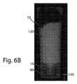
試験2の通気孔のない対照キャップは、オーバフロー液をキャップ内部に捕捉せず、かつ気体が収容容器から放出されるのを可能にしなかった。表2に示すように、試験2の通気孔のない対照キャップは、試験を行った90日後に、試験した全ての配置において、収容容器の外側に視認可能な漏れを有した。図6Bは、キャップを下にした配置で40℃、75% RHで90日間定置した試験2の通気孔のない対照キャップのCTスキャンである。図6Bは、収容容器10及びノズル15内の液体120が収容容器開口部を通って移動し、ノズル15と突起部との間の空隙内に閉じ込められることを示している。図6Bの通気孔のない対照キャップは、液体120がヘッドスペース90又は通気経路内にオーバフローするのを可能にする突起部開口部、又は気体が収容容器10から出るのを可能にする通気経路を有していない。そのような構造は、ノズルと突起部の内側表面との間の空隙への気体及び液体の流れを制限する。その結果、液体はノズルのねじ山の上に蓄積し、キャップを収容容器から取り外す前後に視覚的に視認可能な漏れ及びユーザーに対する汚れを生じさせる可能性がある。
The control cap without vents in
キャップ性能試験は、通気キャップが、気体を放出しかつ収容容器からのオーバフロー液を捕捉することによって、収容容器からの口腔ケア組成物の視認可能な漏れを適切に防止することを示している。 The cap performance test shows that the vent cap adequately prevents visible leakage of the oral care composition from the containment vessel by releasing gas and capturing overflow liquid from the containment vessel.
本明細書において開示される寸法及び値は、記載される正確な数値に厳密に限定されるとして理解されないものとする。代わりに、別途指定されない限り、各々のかかる寸法は、記載される値及びその値の周辺の機能的に同等な範囲の両方を意味することが意図される。例えば、「40mm」として開示される寸法は、「約40mm」を意味することが意図される。 The dimensions and values disclosed herein are not to be understood as being strictly limited to the exact numerical values recited. Instead, unless otherwise specified, each such dimension is intended to mean both the recited value and a functionally equivalent range surrounding that value. For example, a dimension disclosed as “40 mm” is intended to mean “about 40 mm”.
いかなる相互参照される又は関連する特許若しくは出願、及び本出願がその優先権又は利益を主張するいかなる特許出願若しくは特許も含む、本明細書において引用されるあらゆる文書は、明示的に除外されるか又は別途限定されない限り、その全体として参照により本明細書に組み込まれる。いずれの文書の引用も、それが、本明細書において開示若しくは特許請求されるいかなる発明に関しても、先行技術であること、又はそれが単独で、若しくは任意の他の参考文献(1つ又は複数)との任意の組み合わせにおいて、任意のかかる発明を教示、提唱、若しくは開示することを認めるものではない。更に、本文書における用語のいずれかの意味又は定義が、参考により組み込まれる文書における同じ用語のいずれかの意味又は定義と対立する範囲では、本文書におけるその用語に与えられた意味又は定義を優先するものとする。 Are any documents cited in this specification explicitly excluded, including any cross-referenced or related patents or applications and any patent applications or patents for which this application claims priority or benefit? Or, unless otherwise limited, is hereby incorporated by reference in its entirety. Citation of any document is prior art with respect to any invention disclosed or claimed herein, or by itself or any other reference (s) It is not permitted to teach, advocate, or disclose any such invention in any combination with. In addition, to the extent that any meaning or definition of a term in this document conflicts with any meaning or definition of the same term in a document incorporated by reference, the meaning or definition given to that term in this document takes precedence. It shall be.
本発明の特定の実施例を例示及び説明してきたが、本発明の趣旨及び範囲から逸脱することなく、他の様々な変更及び修正を行うことができることは当業者には明白であろう。したがって、添付の特許請求の範囲において、本発明の範囲内にある全てのかかる変更及び修正を網羅することが意図される。 While particular embodiments of the present invention have been illustrated and described, it would be obvious to those skilled in the art that various other changes and modifications can be made without departing from the spirit and scope of the invention. Accordingly, it is intended by the appended claims to cover all such changes and modifications that are within the scope of this invention.
Claims (12)
インサートであって、
フロアパンと、
前記フロアパンに結合された突起部近位端から、前記突起部近位端から長手方向遠方の突起部遠位端まで延在する突起部と、を含み、
前記突起部が前記突起部を貫通する突起部開口部を画定する、インサートと、
シェルであって、
前記フロアパンに結合されかつ前記フロアパンから長手方向に外側に延在する外側スカートと、
前記外側スカートに結合された上部と、を含み、
前記上部及び前記外側スカートが前記フロアパンと前記上部との間にヘッドスペースを画定し、
前記突起部が前記ヘッドスペースの一部分内まで延在する、シェルと、
前記ヘッドスペースと大気との間を流体連通する通気孔と、を備え、
前記フロアパンに結合された壁近位端から、前記壁近位端から長手方向遠方の壁遠位端まで延在する内側保持壁を更に備え、前記内側保持壁及び前記外側スカートがそれらの間にチャネルを画定する、通気キャップ。 A vent cap having a longitudinal axis,
An insert,
Floor bread,
A protrusion extending from a protrusion proximal end coupled to the floor pan to a protrusion distal end longitudinally far from the protrusion proximal end;
An insert defining a protrusion opening through which the protrusion penetrates the protrusion; and
A shell,
An outer skirt coupled to the floor pan and extending outwardly from the floor pan in a longitudinal direction;
An upper portion coupled to the outer skirt,
The top and the outer skirt define a headspace between the floor pan and the top;
A shell, wherein the protrusion extends into a portion of the headspace;
E Bei and a vent in fluid communication between said headspace and the atmosphere,
An inner retaining wall extending from a wall proximal end coupled to the floor pan to a longitudinally distal wall distal end from the wall proximal end, the inner retaining wall and the outer skirt therebetween A vent cap that defines the channel .
Applications Claiming Priority (3)
| Application Number | Priority Date | Filing Date | Title |
|---|---|---|---|
| US14/461,343 US9926109B2 (en) | 2014-08-15 | 2014-08-15 | Vented cap assembly |
| US14/461,343 | 2014-08-15 | ||
| PCT/US2015/044541 WO2016025413A1 (en) | 2014-08-15 | 2015-08-11 | Vented cap assembly |
Publications (2)
| Publication Number | Publication Date |
|---|---|
| JP2017526585A JP2017526585A (en) | 2017-09-14 |
| JP6416377B2 true JP6416377B2 (en) | 2018-10-31 |
Family
ID=53969434
Family Applications (1)
| Application Number | Title | Priority Date | Filing Date |
|---|---|---|---|
| JP2017505804A Expired - Fee Related JP6416377B2 (en) | 2014-08-15 | 2015-08-11 | Vent cap assembly |
Country Status (13)
| Country | Link |
|---|---|
| US (2) | US9926109B2 (en) |
| EP (1) | EP3180256B1 (en) |
| JP (1) | JP6416377B2 (en) |
| CN (1) | CN106573702B (en) |
| AR (1) | AR101500A1 (en) |
| AU (1) | AU2015301964B2 (en) |
| BR (1) | BR112017002742B1 (en) |
| CA (1) | CA2955491C (en) |
| ES (1) | ES2687419T3 (en) |
| MX (1) | MX2017002098A (en) |
| PL (1) | PL3180256T3 (en) |
| RU (1) | RU2676562C2 (en) |
| WO (1) | WO2016025413A1 (en) |
Families Citing this family (5)
| Publication number | Priority date | Publication date | Assignee | Title |
|---|---|---|---|---|
| US9815598B2 (en) * | 2013-08-01 | 2017-11-14 | Mars, Incorporated | Container |
| US9926109B2 (en) | 2014-08-15 | 2018-03-27 | The Procter & Gamble Company | Vented cap assembly |
| DE102019101556A1 (en) * | 2019-01-23 | 2020-07-23 | Wabco Gmbh | Vent cap on a solenoid valve in compressed air systems, for example for vehicles |
| US20220315299A1 (en) * | 2019-05-14 | 2022-10-06 | Airnov, Inc. | Receptacle for holding an active substance and corresponding closure and container with such a receptacle |
| FR3120359B1 (en) * | 2021-03-05 | 2023-10-27 | Horus Pharma | CONDITIONING DEVICE WITH INTEGRATED AERATION SYSTEM |
Family Cites Families (38)
| Publication number | Priority date | Publication date | Assignee | Title |
|---|---|---|---|---|
| US2242966A (en) | 1939-03-13 | 1941-05-20 | Pneumatic Cap & Seal Corp | Bottle closure |
| US3628697A (en) * | 1969-02-08 | 1971-12-21 | D P Inserts Ltd | Drip-preventing device for bottle |
| JPS4857450U (en) * | 1971-11-06 | 1973-07-21 | ||
| US4337875A (en) | 1981-03-12 | 1982-07-06 | Atwood Vacuum Machine Company | Overflow and vent cap for a container |
| US5108009A (en) * | 1986-02-12 | 1992-04-28 | Lever Brothers Company, Division Of Conopco, Inc. | Leak and drip resistant storage dispensing and measuring package |
| US4842165A (en) * | 1987-08-28 | 1989-06-27 | The Procter & Gamble Company | Resilient squeeze bottle package for dispensing viscous products without belching |
| EG21314A (en) * | 1992-07-16 | 2000-10-31 | Driutt Rodney Malcolm | Tamper evident closure |
| DE4332885A1 (en) * | 1992-09-28 | 1994-03-31 | Colgate Palmolive Co | Squeezable dispenser for toothpaste etc. - has inner flexible disposable container fitting into outer container and closed by cap and one-way locking valves |
| US5431306A (en) * | 1993-12-31 | 1995-07-11 | Innovative Molding, Inc. | Drain back container with internal thread |
| JPH09255009A (en) * | 1996-03-28 | 1997-09-30 | Sekisui Chem Co Ltd | Liquid container |
| US5909977A (en) * | 1997-03-31 | 1999-06-08 | Kuo; Youti | Dentifrice dispensing toothbrush with refillable cartridge |
| US5931356A (en) * | 1997-06-27 | 1999-08-03 | Dart Industries Inc. | Dispenser for oil/vinegar bottle |
| JP3068597B1 (en) * | 1999-03-02 | 2000-07-24 | 日本酸素株式会社 | Internal pressure rise prevention container |
| US6202870B1 (en) | 1999-03-29 | 2001-03-20 | Woodrow W. Pearce | Venting cap |
| WO2002060765A2 (en) * | 2001-01-31 | 2002-08-08 | Long Shot Products, Ltd. | Sealing cap having a deformable sealant material |
| US6659297B2 (en) * | 2001-11-28 | 2003-12-09 | Owens-Illinois Closure Inc. | Tamper-indicating closure, container, package and methods of manufacture |
| US20040094554A1 (en) * | 2002-06-24 | 2004-05-20 | Grybush Anthony F. | Vented fuel tank cap |
| US20030234254A1 (en) * | 2002-06-24 | 2003-12-25 | Grybush Anthony F. | Vented fuel tank cap |
| CN2606063Y (en) * | 2003-04-08 | 2004-03-10 | 林松荣 | Spice jar |
| US20130193170A1 (en) | 2003-05-28 | 2013-08-01 | Robert A. Lehmkuhl | Dispensing cap for a squeezeable bottle |
| US7204382B2 (en) * | 2003-09-15 | 2007-04-17 | Thomas Edward Cezeaux | Drinking tube and cap assembly |
| US7048140B1 (en) * | 2003-12-12 | 2006-05-23 | Brunswick Corporation | Vented liquid containment device |
| US8518323B2 (en) * | 2004-05-25 | 2013-08-27 | Vapex Environmental Technologies, Inc. | Apparatus and process for oxidizing a vapor-phase substrate with low dose zone |
| EP1647320B8 (en) * | 2004-10-15 | 2007-10-03 | ARGO-HYTOS GmbH | Breathing filter for a tank |
| US7117654B2 (en) | 2004-12-29 | 2006-10-10 | Seaquist Closures Foreign, Inc. | Packaging process employing a closure orifice seal vent |
| FR2891530B1 (en) * | 2005-10-04 | 2007-12-07 | Valois Sas | RECOVERY BODY, METHOD FOR MANUFACTURING SAME, AND FLUID PRODUCT DISPENSER USING SAME |
| FR2891533B1 (en) * | 2005-10-04 | 2007-12-07 | Valois Sas | RECOVERY BODY, METHOD FOR MANUFACTURING SAME, AND FLUID PRODUCT DISPENSER USING SAME |
| US20090108006A1 (en) | 2007-10-26 | 2009-04-30 | Coollid Corporation | Beverage container lid having liquid cooling effect |
| JP5135125B2 (en) * | 2008-08-28 | 2013-01-30 | 株式会社吉野工業所 | Application container |
| FR2945518B1 (en) * | 2009-05-18 | 2011-05-27 | Maitrise & Innovation | ANTI-DROP CAP WITH MOBILE CAP REMOVAL ELASTICALLY |
| US8511492B2 (en) * | 2010-08-20 | 2013-08-20 | The Clorox Company | Bottle with handle venting inlet and child resistant flip-top closure with pouring spout and drainback hole |
| CN202108629U (en) * | 2011-06-02 | 2012-01-11 | 重庆宗申通用动力机械有限公司 | Fuel tank cap of general purpose engine |
| SG11201403463TA (en) * | 2011-12-21 | 2014-07-30 | Advanced Tech Materials | Liner-based shipping and dispensing systems |
| CN202594055U (en) * | 2011-12-22 | 2012-12-12 | 诸峥嵘 | Thread telescopic bottleneck |
| CN104302726A (en) * | 2012-03-01 | 2015-01-21 | 格雷斯公司 | Closure liner composition with improved oxygen reduction |
| GB201212164D0 (en) * | 2012-07-06 | 2012-08-22 | Obrist Closures Switzerland | A dispensing closure |
| GB2519205B (en) * | 2013-08-16 | 2017-02-08 | Mwv Slatersville Llc | Two-piece child-resistant dispensing closure |
| US9926109B2 (en) | 2014-08-15 | 2018-03-27 | The Procter & Gamble Company | Vented cap assembly |
-
2014
- 2014-08-15 US US14/461,343 patent/US9926109B2/en active Active
-
2015
- 2015-08-11 MX MX2017002098A patent/MX2017002098A/en unknown
- 2015-08-11 AU AU2015301964A patent/AU2015301964B2/en active Active
- 2015-08-11 JP JP2017505804A patent/JP6416377B2/en not_active Expired - Fee Related
- 2015-08-11 CA CA2955491A patent/CA2955491C/en active Active
- 2015-08-11 RU RU2017102223A patent/RU2676562C2/en not_active IP Right Cessation
- 2015-08-11 CN CN201580043817.XA patent/CN106573702B/en active Active
- 2015-08-11 EP EP15754072.5A patent/EP3180256B1/en not_active Not-in-force
- 2015-08-11 PL PL15754072T patent/PL3180256T3/en unknown
- 2015-08-11 BR BR112017002742-9A patent/BR112017002742B1/en not_active IP Right Cessation
- 2015-08-11 AR ARP150102584A patent/AR101500A1/en active IP Right Grant
- 2015-08-11 WO PCT/US2015/044541 patent/WO2016025413A1/en active Application Filing
- 2015-08-11 ES ES15754072.5T patent/ES2687419T3/en active Active
-
2018
- 2018-02-07 US US15/890,400 patent/US10358267B2/en active Active
Also Published As
| Publication number | Publication date |
|---|---|
| AU2015301964B2 (en) | 2018-03-15 |
| US20160046413A1 (en) | 2016-02-18 |
| RU2676562C2 (en) | 2019-01-09 |
| WO2016025413A1 (en) | 2016-02-18 |
| CA2955491C (en) | 2019-08-27 |
| CN106573702B (en) | 2019-05-17 |
| US9926109B2 (en) | 2018-03-27 |
| BR112017002742A2 (en) | 2017-12-26 |
| PL3180256T3 (en) | 2019-01-31 |
| US20180162604A1 (en) | 2018-06-14 |
| CA2955491A1 (en) | 2016-02-18 |
| ES2687419T3 (en) | 2018-10-25 |
| RU2017102223A (en) | 2018-09-17 |
| AR101500A1 (en) | 2016-12-21 |
| EP3180256B1 (en) | 2018-07-04 |
| US10358267B2 (en) | 2019-07-23 |
| BR112017002742B1 (en) | 2021-11-16 |
| EP3180256A1 (en) | 2017-06-21 |
| MX2017002098A (en) | 2017-05-04 |
| CN106573702A (en) | 2017-04-19 |
| RU2017102223A3 (en) | 2018-09-17 |
| AU2015301964A1 (en) | 2017-02-02 |
| JP2017526585A (en) | 2017-09-14 |
Similar Documents
| Publication | Publication Date | Title |
|---|---|---|
| JP6416377B2 (en) | Vent cap assembly | |
| JP5618440B2 (en) | Syringe | |
| US10188111B2 (en) | Pharmaceutically acceptable composition comprising dilute sodium hypochlorite solution | |
| US20110058891A1 (en) | Dental cleanser and stain prevention apparatus | |
| DK164035B (en) | CONTAINER WITH MULTI-COMPONENT DENTALS AND PROCEDURE FOR ITS MANUFACTURING | |
| ES2512724T3 (en) | Packaging for a consumer product | |
| CN103327930A (en) | Device to provide enhanced flossing benefits | |
| JP2007254348A (en) | Inhibitor for preventing body fluid leakage for corpse and apparatus for treating corpse | |
| KR101675989B1 (en) | Eyewater container and method of assembling the same | |
| WO2017014360A1 (en) | Portable interdental brush | |
| JP5149504B2 (en) | Body treatment device | |
| CA2778079C (en) | Toothpaste delivery system | |
| JP4822873B2 (en) | Body fluid leakage prevention device for corpses | |
| CN208864821U (en) | A kind of sealing-plug for plasma bags efferent duct | |
| JP5139895B2 (en) | Lubricating fluid applicator for insertion tube for body fluid leakage prevention agent injection | |
| CN210612277U (en) | Cotton swab and oral care bag with same | |
| JP2013166783A (en) | Dentifrice composition | |
| CN211213640U (en) | Double-layer denture | |
| JP2010162111A (en) | Syringe for dental material | |
| JP2015074456A (en) | Tube container | |
| BR102013007953A2 (en) | PACKAGING DISPENSER AND APPLIER OF PERFUME AND METHOD OF PACKING USE | |
| IT202100013670A1 (en) | Device for containing and dispensing a solution for washing and sanitizing the dental cavity of a patient undergoing dental surgery. | |
| JP2021123362A (en) | Slit structure of tube container mouth-neck body | |
| JP2019077488A (en) | Tube container protector | |
| ITMI940425A1 (en) | CONNECTION SYSTEMS IN PARTICULAR FOR PERITONEAL DIALYSIS |
Legal Events
| Date | Code | Title | Description |
|---|---|---|---|
| A977 | Report on retrieval |
Free format text: JAPANESE INTERMEDIATE CODE: A971007 Effective date: 20180112 |
|
| A131 | Notification of reasons for refusal |
Free format text: JAPANESE INTERMEDIATE CODE: A131 Effective date: 20180123 |
|
| A601 | Written request for extension of time |
Free format text: JAPANESE INTERMEDIATE CODE: A601 Effective date: 20180423 |
|
| A601 | Written request for extension of time |
Free format text: JAPANESE INTERMEDIATE CODE: A601 Effective date: 20180622 |
|
| A521 | Request for written amendment filed |
Free format text: JAPANESE INTERMEDIATE CODE: A523 Effective date: 20180720 |
|
| TRDD | Decision of grant or rejection written | ||
| A01 | Written decision to grant a patent or to grant a registration (utility model) |
Free format text: JAPANESE INTERMEDIATE CODE: A01 Effective date: 20180907 |
|
| A61 | First payment of annual fees (during grant procedure) |
Free format text: JAPANESE INTERMEDIATE CODE: A61 Effective date: 20181003 |
|
| R150 | Certificate of patent or registration of utility model |
Ref document number: 6416377 Country of ref document: JP Free format text: JAPANESE INTERMEDIATE CODE: R150 |
|
| LAPS | Cancellation because of no payment of annual fees |