JP6416123B2 - Shock absorber with variable damping profile - Google Patents
Shock absorber with variable damping profile Download PDFInfo
- Publication number
- JP6416123B2 JP6416123B2 JP2015555209A JP2015555209A JP6416123B2 JP 6416123 B2 JP6416123 B2 JP 6416123B2 JP 2015555209 A JP2015555209 A JP 2015555209A JP 2015555209 A JP2015555209 A JP 2015555209A JP 6416123 B2 JP6416123 B2 JP 6416123B2
- Authority
- JP
- Japan
- Prior art keywords
- shock tube
- depth
- outer cylinder
- groove
- holes
- Prior art date
- Legal status (The legal status is an assumption and is not a legal conclusion. Google has not performed a legal analysis and makes no representation as to the accuracy of the status listed.)
- Active
Links
Images


Classifications
-
- F—MECHANICAL ENGINEERING; LIGHTING; HEATING; WEAPONS; BLASTING
- F16—ENGINEERING ELEMENTS AND UNITS; GENERAL MEASURES FOR PRODUCING AND MAINTAINING EFFECTIVE FUNCTIONING OF MACHINES OR INSTALLATIONS; THERMAL INSULATION IN GENERAL
- F16F—SPRINGS; SHOCK-ABSORBERS; MEANS FOR DAMPING VIBRATION
- F16F9/00—Springs, vibration-dampers, shock-absorbers, or similarly-constructed movement-dampers using a fluid or the equivalent as damping medium
- F16F9/32—Details
- F16F9/50—Special means providing automatic damping adjustment, i.e. self-adjustment of damping by particular sliding movements of a valve element, other than flexions or displacement of valve discs; Special means providing self-adjustment of spring characteristics
- F16F9/512—Means responsive to load action, i.e. static load on the damper or dynamic fluid pressure changes in the damper, e.g. due to changes in velocity
-
- F—MECHANICAL ENGINEERING; LIGHTING; HEATING; WEAPONS; BLASTING
- F16—ENGINEERING ELEMENTS AND UNITS; GENERAL MEASURES FOR PRODUCING AND MAINTAINING EFFECTIVE FUNCTIONING OF MACHINES OR INSTALLATIONS; THERMAL INSULATION IN GENERAL
- F16F—SPRINGS; SHOCK-ABSORBERS; MEANS FOR DAMPING VIBRATION
- F16F9/00—Springs, vibration-dampers, shock-absorbers, or similarly-constructed movement-dampers using a fluid or the equivalent as damping medium
- F16F9/32—Details
- F16F9/34—Special valve constructions; Shape or construction of throttling passages
- F16F9/346—Throttling passages in the form of slots arranged in cylinder walls
-
- F—MECHANICAL ENGINEERING; LIGHTING; HEATING; WEAPONS; BLASTING
- F16—ENGINEERING ELEMENTS AND UNITS; GENERAL MEASURES FOR PRODUCING AND MAINTAINING EFFECTIVE FUNCTIONING OF MACHINES OR INSTALLATIONS; THERMAL INSULATION IN GENERAL
- F16F—SPRINGS; SHOCK-ABSORBERS; MEANS FOR DAMPING VIBRATION
- F16F9/00—Springs, vibration-dampers, shock-absorbers, or similarly-constructed movement-dampers using a fluid or the equivalent as damping medium
- F16F9/32—Details
- F16F9/44—Means on or in the damper for manual or non-automatic adjustment; such means combined with temperature correction
-
- F—MECHANICAL ENGINEERING; LIGHTING; HEATING; WEAPONS; BLASTING
- F16—ENGINEERING ELEMENTS AND UNITS; GENERAL MEASURES FOR PRODUCING AND MAINTAINING EFFECTIVE FUNCTIONING OF MACHINES OR INSTALLATIONS; THERMAL INSULATION IN GENERAL
- F16F—SPRINGS; SHOCK-ABSORBERS; MEANS FOR DAMPING VIBRATION
- F16F9/00—Springs, vibration-dampers, shock-absorbers, or similarly-constructed movement-dampers using a fluid or the equivalent as damping medium
- F16F9/32—Details
- F16F9/48—Arrangements for providing different damping effects at different parts of the stroke
Description
本願は可変減衰プロファイルを有するショックアブソーバに関する。 The present application relates to a shock absorber having a variable damping profile.
ほとんどの従来の調節不可能なショックアブソーバにおいては、ストロークプロファイルに対比して進行性、矩形波、ダッシュポット、又は自己補正の衝撃力をそれぞれ送達するように設計することができるが、各々が単一の減衰プロファイルを有する個別のショックアブソーバユニットの中からユーザが選択をしなければならなかった。従って、これら従来のショックアブソーバでは、選択された特定のストロークプロファイルに対比した衝撃力の狭い帯域にパフォーマンスが調節され、負荷及び衝撃速度の変動を含む動作状態の変化を保証することができなかった。他の従来のショックアブソーバでは、矩形波又はダッシュポット減衰プロファイルとしてのみ減衰を調節可能であるために、特定の脆弱な負荷が適用される状態には適さない可能性があった。そのようなショックアブソーバの一例が特許文献1に記載されているが、ここでショックアブソーバには、オイルの流路を提供するためだけでなく、オリフィスからの流体の流れを遮断又は計測するための両方の目的のために螺旋状の溝が採用されている。 Most conventional non-adjustable shock absorbers can be designed to deliver progressive, square wave, dashpot, or self-correcting impact forces, respectively, relative to the stroke profile. The user had to make a choice from among individual shock absorber units with a single damping profile. Therefore, in these conventional shock absorbers, the performance is adjusted to a narrow band of impact force compared with the selected specific stroke profile, and it is not possible to guarantee a change in operating state including fluctuations in load and impact speed. . In other conventional shock absorbers, the damping can only be adjusted as a square wave or dashpot damping profile, which may not be suitable for situations where certain fragile loads are applied. An example of such a shock absorber is described in Patent Document 1, wherein the shock absorber not only provides an oil flow path but also blocks or measures the flow of fluid from the orifice. Helical grooves are employed for both purposes.
一方、本明細書に開示されたショックアブソーバ装置は単一で多様な範囲にわたる用途を兼ね備える。本明細書には、単一のショックアブソーバ内における様々な構成要素(例えば、ピストンヘッド、ショックチューブ、シリンダ端、外部シリンダ、及び調節機構)の間の相互作用の新規な組み合わせが開示される。従来の装置において最も複雑度が高いものであっても、例えば三つの部品の間の相互作用に限定されていたこの工業分野において、このような相互作用は未だ発見されていない。本明細書に開示された構成要素を併せて検討し、相互に関連する単一のアセンブリとして設計することで、単一の装置内において多様な範囲にわたる用途を兼ね備えることが可能になる。 On the other hand, the shock absorber device disclosed in this specification has a single and diverse range of uses. Disclosed herein is a novel combination of interactions between various components (eg, piston head, shock tube, cylinder end, outer cylinder, and adjustment mechanism) within a single shock absorber. Even the most complex of conventional devices, no such interaction has yet been discovered in this industrial field, which is limited to, for example, the interaction between three parts. Considering the components disclosed herein together and designing them as a single, interrelated assembly allows for a wide range of applications within a single device.
本発明の例示的な一実施形態は、外部シリンダのハウジング部材と、ショックチューブと、ピストンと、アキュムレータとを含むエネルギー吸収装置である。外部シリンダは先端と、基端と、内壁と、外部シリンダの内壁に形成された流路とを有する。流路は実質的に外部シリンダの長さに沿って延び、アキュムレータと流体連通する。ピストンはヘッド部とロッド部とを含む。ヘッド部はショックチューブ内に摺動可能に保持され、ロッド部はヘッド部から外部シリンダの基端を通して延び、且つ、移動中に外部本体に係合する。アキュムレータは外部シリンダ内に収容され、且つ、ピストンのヘッド部が外部シリンダの先端に向かって移動する時にショックチューブの内部から流体を回収する。 One exemplary embodiment of the present invention is an energy absorbing device that includes an outer cylinder housing member, a shock tube, a piston, and an accumulator. The outer cylinder has a tip, a base end, an inner wall, and a flow path formed in the inner wall of the outer cylinder. The flow path extends substantially along the length of the outer cylinder and is in fluid communication with the accumulator. The piston includes a head portion and a rod portion. The head portion is slidably held in the shock tube, and the rod portion extends from the head portion through the proximal end of the outer cylinder and engages the outer body during movement. The accumulator is housed in the outer cylinder, and collects fluid from the inside of the shock tube when the piston head moves toward the tip of the outer cylinder.
ショックチューブは外部シリンダ内に回転可能に取り付けられ、且つ、内表面と、外表面と、ショックチューブの長軸に沿って一列に並んだ一群の穴とを有する。各穴は流体がその中を通過することを許容するようにショックチューブの内表面からショックチューブの外表面へと貫通する。ショックチューブはまた、ショックチューブの外表面上にテーパ状溝を有する。このテーパ状溝は一群の一列に並んだ穴にわたる、ショックチューブの長軸に沿った長さを有する。テーパ状溝は一群の一列に並んだ穴の位置から開始されるが、これはショックチューブの外表面内へ向かう第一深度を形成する。テーパ状溝はショックチューブの周囲の別の位置で終了するが、これはショックチューブの外表面内へ向かう第二深度を形成する。第二深度は第一深度よりも浅く、テーパ状溝の深度は第一深度から第二深度へとテーパ状になる。 The shock tube is rotatably mounted in the outer cylinder and has an inner surface, an outer surface, and a group of holes arranged in a line along the major axis of the shock tube. Each hole penetrates from the inner surface of the shock tube to the outer surface of the shock tube to allow fluid to pass therethrough. The shock tube also has a tapered groove on the outer surface of the shock tube. The tapered groove has a length along the long axis of the shock tube that spans a group of aligned holes. The tapered groove begins at the location of a group of rows of holes, which forms a first depth into the outer surface of the shock tube. The tapered groove terminates at another location around the shock tube, which creates a second depth into the outer surface of the shock tube. The second depth is shallower than the first depth, and the depth of the tapered groove tapers from the first depth to the second depth.
ショックチューブと外部シリンダとの間の相対的な回転によって、ショックチューブから一群の一列に並んだ穴と、テーパ状溝と、流路とを通したアキュムレータへの流体の流量を調節可能に変化させるため、テーパ状溝のどの部分を流路と接続するかを変化させる。このような回転によって、エネルギー吸収装置の減衰を変化させる。 Relative rotation between the shock tube and the outer cylinder adjustably changes the flow rate of fluid from the shock tube to the accumulator through a group of aligned holes, tapered grooves and flow paths. Therefore , which part of the tapered groove is connected to the flow path is changed. Such rotation changes the attenuation of the energy absorbing device.
多くの実施形態において、テーパ状溝は実質的にショックチューブの周囲(例えば、ショックチューブの周囲に約350度)に延びてもよい。流路の幅は一群の一列に並んだ穴の幅に少なくとも等しくすることができる。多くの実施形態において、テーパ状溝の第一深度は実質的にショックチューブの厚さであってもよく、テーパ状溝の第二深度は例えばゼロ、又はほぼゼロであってもよい。多くの実施形態において、エネルギー吸収装置の減衰は、所与の時点で流路に接続される点におけるテーパ状溝の幅及び深度の投影面積に基づく。 In many embodiments, the tapered groove around the substantially shock tube (e.g., about 350 degrees around the shock tube) but it may also extend to the. The width of the flow path can be at least equal to the width of the holes in a group. In many embodiments, the first depth of the tapered groove may be substantially the thickness of the shock tube, and the second depth of the tapered groove may be, for example, zero or nearly zero. In many embodiments, the energy absorber attenuation is based on the projected area of the width and depth of the tapered groove at the point connected to the flow path at a given time.
いくつかの実施形態において、エネルギー吸収装置はショックチューブの長軸に沿って一列に並んだ複数の群の穴を含み、各群の一列に並んだ穴はショックチューブの周囲の異なる位置に配置される。このような実施形態では、複数の群の一列に並んだ穴に対応する複数のテーパ状溝を含んでもよい。これらのテーパ状溝はそれぞれ、対応する一群の一列に並んだ穴にわたる、ショックチューブの長軸に沿った長さを有する。各テーパ状溝は対応する一群の一列に並んだ穴の位置から開始される。複数の群の一列に並んだ穴を有する実施形態において、各群の一列に並んだ穴は異なる種類の減衰(例えば、矩形波減衰、ダッシュポット減衰、進行性減衰、又は自己補正減衰)を提供することができる。複数の群の一列に並んだ穴を有する実施形態において、エネルギー吸収装置は一つ以上の流路を含んでもよい。複数の群の一列に並んだ穴と一つの流路とを有する実施形態において、ユーザはどのテーパ状溝を流路に接続するかを選択することができる。代わりに、エネルギー吸収装置は複数の群の一列に並んだ穴に対応する複数の流路を含んでもよく、その場合、各流路は外部シリンダの内壁の周囲の異なる位置に形成される。 In some embodiments, the energy absorber includes a plurality of groups of holes aligned along the long axis of the shock tube, and the aligned holes in each group are located at different locations around the shock tube. The In such embodiments, but it may also include a plurality of tapered grooves corresponding to the holes in a row of a plurality of groups. Each of these tapered grooves has a length along the long axis of the shock tube over a corresponding group of aligned holes. Each tapered groove starts at the position of a corresponding group of holes in a row. In embodiments with multiple groups of aligned holes, each group of aligned holes provides a different type of attenuation (eg, square wave attenuation, dashpot attenuation, progressive attenuation, or self-corrected attenuation). can do. In embodiments having a plurality of groups of aligned holes, the energy absorber may include one or more flow paths. In embodiments having a plurality of groups of aligned holes and one channel, the user can select which tapered groove is connected to the channel. Alternatively, the energy absorbing device may include a plurality of flow paths corresponding to the holes arranged in a row in the plurality of groups, in which case each flow path is formed at a different position around the inner wall of the outer cylinder.
本発明の他の例示的な実施形態は、外部シリンダのハウジング部材と、ショックチューブと、ピストンと、アキュムレータとを含むエネルギー吸収装置である。外部シリンダは先端と、基端と、内壁と、外部シリンダの内壁に形成された流路とを有する。流路は実質的に外部シリンダの長さに沿って延び、アキュムレータと流体連通する。ピストンはヘッド部とロッド部とを含む。ヘッド部はショックチューブ内に摺動可能に保持され、ロッド部はヘッド部から外部シリンダの基端を通して延び、且つ、移動中に外部本体に係合する。アキュムレータは外部シリンダ内に収容され、且つ、ピストンのヘッド部が外部シリンダの先端に向かって移動する時にショックチューブの内部から流体を回収する。 Another exemplary embodiment of the present invention is an energy absorbing device that includes an outer cylinder housing member, a shock tube, a piston, and an accumulator. The outer cylinder has a tip, a base end, an inner wall, and a flow path formed in the inner wall of the outer cylinder. The flow path extends substantially along the length of the outer cylinder and is in fluid communication with the accumulator. The piston includes a head portion and a rod portion. The head portion is slidably held in the shock tube, and the rod portion extends from the head portion through the proximal end of the outer cylinder and engages the outer body during movement. The accumulator is housed in the outer cylinder, and collects fluid from the inside of the shock tube when the piston head moves toward the tip of the outer cylinder.
ショックチューブは外部シリンダ内に回転可能に取り付けられ、且つ、内表面と、外表面と、ショックチューブの長軸に沿って一列に並んだ一群の穴とを有する。各穴は流体がその中を通過することを許容するようにショックチューブの内表面からショックチューブの外表面へと貫通する。ショックチューブはまた、ショックチューブの外表面上に一群の一列に並んだ穴に対応する一群のテーパ状溝を有する。各テーパ状溝は対応する穴の位置から開始されるが、これはショックチューブの外表面内へ向かう第一深度を形成する。各テーパ状溝はショックチューブの周囲の別の位置で終了するが、これはショックチューブの外表面内へ向かう第二深度を形成する。溝の第二深度は溝の第一深度よりも浅く、溝の深度は第一深度から第二深度へとテーパ状になる。 The shock tube is rotatably mounted in the outer cylinder and has an inner surface, an outer surface, and a group of holes arranged in a line along the major axis of the shock tube. Each hole penetrates from the inner surface of the shock tube to the outer surface of the shock tube to allow fluid to pass therethrough. The shock tube also has a group of tapered grooves corresponding to a group of aligned holes on the outer surface of the shock tube. Each tapered groove starts at the position of the corresponding hole, which forms a first depth into the outer surface of the shock tube. Each tapered groove ends at another location around the shock tube, which forms a second depth into the outer surface of the shock tube. The second depth of the groove is shallower than the first depth of the groove, and the depth of the groove tapers from the first depth to the second depth.
ショックチューブと外部シリンダとの間の相対的な回転によって、ショックチューブから一群の一列に並んだ穴と、テーパ状溝と、流路とを通したアキュムレータへの流体の流量を調節可能に変化させるため、テーパ状溝のどの部分を流路と接続するかを変化させる。このような回転によって、エネルギー吸収装置の減衰を変化させる。 Relative rotation between the shock tube and the outer cylinder adjustably changes the flow rate of fluid from the shock tube to the accumulator through a group of aligned holes, tapered grooves and flow paths. Therefore, which part of the tapered groove is connected to the flow path is changed. Such rotation changes the attenuation of the energy absorbing device.
多くの実施形態において、テーパ状溝は実質的にショックチューブの周囲(例えば、ショックチューブの周囲に約350度)に延びてもよい。他の実施形態において、テーパ状溝はショックチューブの周囲の異なる位置で終了することができる。流路の幅は一群の一列に並んだ穴の幅に少なくとも等しくすることができる。多くの実施形態において、テーパ状溝の第一深度は実質的にショックチューブの厚さであってもよく、テーパ状溝の第二深度は例えばゼロ、又はほぼゼロであってもよい。多くの実施形態において、エネルギー吸収装置の減衰は、所与の時点で流路に接続される点におけるテーパ状溝の幅及び深度の投影面積の累積に基づく。 In many embodiments, the tapered groove may extend substantially around the shock tube (eg, about 350 degrees around the shock tube). In other embodiments, the tapered groove can terminate at different locations around the shock tube. The width of the flow path can be at least equal to the width of the holes in a group. In many embodiments, the first depth of the tapered groove may be substantially the thickness of the shock tube, and the second depth of the tapered groove may be, for example, zero or nearly zero. In many embodiments, the attenuation of the energy absorber is based on the cumulative projected area of taper groove width and depth at the point connected to the flow path at a given time.
いくつかの実施形態において、エネルギー吸収装置はショックチューブの長軸に沿って一列に並んだ複数の群の穴を含み、各群の一列に並んだ穴はショックチューブの周囲の異なる位置に配置される。このような実施形態では、複数の群の一列に並んだ穴に対応する複数の群のテーパ状溝を含んでもよく、各群のテーパ状溝は対応する一群の一列に並んだ穴の位置から開始される。複数の群の一列に並んだ穴を有する実施形態において、各群の一列に並んだ穴は異なる種類の減衰(例えば、矩形波減衰、ダッシュポット減衰、進行性減衰、又は自己補正減衰)を提供することができる。複数の群の一列に並んだ穴を有する実施形態において、エネルギー吸収装置は一つ以上の流路を含んでもよい。複数の群の一列に並んだ穴と一つの流路とを有する実施形態において、ユーザはテーパ状溝のどの群を流路に接続するかを選択することができる。代わりに、エネルギー吸収装置は複数の群のテーパ状溝に対応する複数の流路を含んでもよく、その場合、各流路は外部シリンダの内壁の周囲の異なる位置に形成される。 In some embodiments, the energy absorber includes a plurality of groups of holes aligned along the long axis of the shock tube, and the aligned holes in each group are located at different locations around the shock tube. The In such an embodiment, a plurality of groups of tapered grooves corresponding to the holes arranged in a row of the plurality of groups may be included, and the tapered grooves of each group are formed from the positions of the holes arranged in a row of the corresponding group. Be started. In embodiments with multiple groups of aligned holes, each group of aligned holes provides a different type of attenuation (eg, square wave attenuation, dashpot attenuation, progressive attenuation, or self-corrected attenuation). can do. In embodiments having a plurality of groups of aligned holes, the energy absorber may include one or more flow paths. In embodiments having a plurality of groups of aligned holes and one flow path, the user can select which group of tapered grooves to connect to the flow path. Alternatively, the energy absorbing device may include a plurality of flow paths corresponding to a plurality of groups of tapered grooves, where each flow path is formed at a different location around the inner wall of the outer cylinder.
本発明の他の例示的な実施形態は、外部シリンダのハウジング部材と、ショックチューブと、ピストンと、アキュムレータとを含むエネルギー吸収装置である。外部シリンダは先端と、基端と、内壁と、外部シリンダの内壁に形成された流路とを有する。流路は実質的に外部シリンダの長さに沿って延び、アキュムレータと流体連通する。ピストンはヘッド部とロッド部とを含む。ヘッド部はショックチューブ内に摺動可能に保持され、ロッド部はヘッド部から外部シリンダの基端を通して延び、且つ、移動中に外部本体に係合する。アキュムレータは外部シリンダ内に収容され、且つ、ピストンのヘッド部が外部シリンダの先端に向かって移動する時にショックチューブの内部から流体を回収する。 Another exemplary embodiment of the present invention is an energy absorbing device that includes an outer cylinder housing member, a shock tube, a piston, and an accumulator. The outer cylinder has a tip, a base end, an inner wall, and a flow path formed in the inner wall of the outer cylinder. The flow path extends substantially along the length of the outer cylinder and is in fluid communication with the accumulator. The piston includes a head portion and a rod portion. The head portion is slidably held in the shock tube, and the rod portion extends from the head portion through the proximal end of the outer cylinder and engages the outer body during movement. The accumulator is housed in the outer cylinder, and collects fluid from the inside of the shock tube when the piston head moves toward the tip of the outer cylinder.
ショックチューブは外部シリンダ内に回転可能に取り付けられ、且つ、内表面と、外表面と、複数の群の穴とを有する。各群の穴はショックチューブの周囲の異なる位置に配置され、各穴は流体がその中を通過することを許容するようにショックチューブの内表面からショックチューブの外表面へと貫通する。 The shock tube is rotatably mounted in the outer cylinder and has an inner surface, an outer surface, and a plurality of groups of holes. Each group of holes is located at a different location around the shock tube, and each hole penetrates from the inner surface of the shock tube to the outer surface of the shock tube to allow fluid to pass therethrough.
流路は穴の複数の群の内の一つの群とともに一時に整合するような幅を有する。ショックチューブと外部シリンダとの間の相対的な回転によって、ショックチューブから流路とともに整合した穴と、流路とを通したアキュムレータへの流体の流量を選択可能に変化させるため、穴のどの群が流路とともに整合するかを変化させる。このような回転によって、エネルギー吸収装置の減衰を変化させる。 The flow path has a width that aligns with one group of the plurality of holes at a time. The relative rotation between the shock tube and the outer cylinder allows a selectable change in the flow rate of fluid from the shock tube to the accumulator through the flow path and the holes aligned with the flow path. Change the alignment with the flow path. Such rotation changes the attenuation of the energy absorbing device.
多くの実施形態において、各群の穴は異なる種類の減衰(例えば、矩形波減衰、ダッシュポット減衰、進行性減衰、又は自己補正減衰)を提供することができる。いくつかの実施形態において流路はその長さに沿って幅が変化し、いくつかの実施形態において複数の群の穴はショックチューブの周囲に螺旋状に配置することができる。 In many embodiments, each group of holes can provide a different type of attenuation (eg, square wave attenuation, dashpot attenuation, progressive attenuation, or self-correcting attenuation). In some embodiments, the flow path varies in width along its length, and in some embodiments, multiple groups of holes can be arranged helically around the shock tube.
開示された実施形態の何れかにおいて、エネルギー吸収装置はまた、外部シリンダの基端にシリンダ端と、シリンダ端の外表面上に端溝と、シリンダ端に第一オリフィスと、ショックチューブに第二オリフィスとを含んでもよい。端溝はシリンダ端の外表面上の第一の位置から開始されるが、これはシリンダ端の外表面内へ向かう第一深度を形成する。端溝はシリンダ端の周囲の第二の位置で終了するが、これはシリンダ端の外表面内へ向かう第二深度を形成する。端溝の第二深度は端溝の第一深度よりも浅く、端溝の深度は端溝の第一深度から端溝の第二深度へとテーパ状になる。(シリンダ端の)第一オリフィスはショックチューブの内部と端溝とに流体連通し、且つ、ピストンのヘッド部が外部シリンダの基端に向かって移動する時にショックチューブの内部から端溝へと流体が流れることを許容する。(ショックチューブの)第二オリフィスは端溝とアキュムレータとに流体連通し、且つ、ピストンのヘッド部が外部シリンダの基端に向かって移動する時に端溝からアキュムレータへと流体が流れることを許容する。ショックチューブと外部シリンダとの間の相対的な回転によって、ショックチューブから(シリンダ端の)第一オリフィスと、端溝と、(ショックチューブの)第二オリフィスとを通したアキュムレータへの流体の流量を調節可能に変化させるため、端溝のどの部分を(ショックチューブの)第二オリフィスと接続するかを変化させる。このような回転によって、エネルギー吸収装置の減衰を変化させる。 In any of the disclosed embodiments, the energy absorber also includes a cylinder end at the proximal end of the outer cylinder, an end groove on the outer surface of the cylinder end, a first orifice at the cylinder end, and a second at the shock tube. And an orifice. The end groove starts from a first position on the outer surface of the cylinder end, which forms a first depth into the outer surface of the cylinder end. The end groove ends at a second position around the cylinder end, which forms a second depth into the outer surface of the cylinder end. The second depth of the end groove is shallower than the first depth of the end groove, and the end groove depth tapers from the first depth of the end groove to the second depth of the end groove. The first orifice (at the cylinder end) is in fluid communication with the shock tube interior and end groove, and when the piston head moves toward the proximal end of the external cylinder, fluid flows from the shock tube interior to the end groove. Is allowed to flow. The second orifice (of the shock tube) is in fluid communication with the end groove and the accumulator and allows fluid to flow from the end groove to the accumulator as the piston head moves toward the proximal end of the outer cylinder. . Relative rotation between the shock tube and the outer cylinder causes fluid flow from the shock tube to the accumulator through the first orifice (at the cylinder end), the end groove, and the second orifice (at the shock tube). In order to change the angle, it is changed which part of the end groove is connected to the second orifice (of the shock tube). Such rotation changes the attenuation of the energy absorbing device.
上記の内容は、同様の参照番号が異なる図面を通して同様の部分を示す添付の図面に示すように、本発明の例示的な実施形態についての以下のより詳細な説明から明らかになるであろう。図面は必ずしも一定の縮尺ではなく、むしろ本発明の実施形態を説明することに重点を置く。 The foregoing will become apparent from the following more detailed description of exemplary embodiments of the invention, as illustrated in the accompanying drawings, in which like reference numerals designate like parts throughout the different views. The drawings are not necessarily to scale, emphasis instead being placed upon illustrating embodiments of the invention.
本発明の例示的な実施形態の説明は以下の通りである。
本明細書には、単一のショックアブソーバ内における様々な構成要素(例えば、ピストンヘッド、ショックチューブ、シリンダ端、外部シリンダ、及び調節機構)の特徴の間の相互作用の新規な組み合わせが開示される。このような部品を協調して相互作用させ、予測可能に動作させるための設計及び開発は明白でも容易でもない。非線形的な流れ、流路、複数の流路の間の相互作用効果、また、装置の顧客志向に応じてアクティブ又は非アクティブとする流路についての熟考された工学技術は、未だ誰も実現できていない。本明細書には、指定された用途において最も有利なストローク減衰プロファイルに対比した衝撃力を選択し、従来は単一装置内に兼ね備えることのできなかった減衰特性の選択という技術を単一のショックアブソーバ内に兼ね備えることができる装置が開示される。これによってショックアブソーバのユーザは単一且つ単純な製品の選択決定を行い、従ってユーザがショックアブソーバの特定の用途のために所望する正確なパフォーマンスを発揮するように装置を調節することが可能になる。
A description of exemplary embodiments of the invention follows.
Disclosed herein is a novel combination of interactions between features of various components (eg, piston head, shock tube, cylinder end, outer cylinder, and adjustment mechanism) within a single shock absorber. The Designing and developing such parts to interact in concert and operate predictably is not obvious or easy. Well-developed engineering techniques for non-linear flow, flow paths, interaction effects between multiple flow paths, and flow paths that are active or inactive depending on the customer orientation of the device can still be realized by anyone Not. This specification describes a technique for selecting shock characteristics relative to the most advantageous stroke damping profile for a given application and selecting damping characteristics that could not previously be combined in a single device. An apparatus that can be combined in an absorber is disclosed. This allows the shock absorber user to make a single and simple product selection decision and thus adjust the device to deliver the exact performance desired by the user for the particular application of the shock absorber. .
図1は、本発明の例示的な一実施形態に係るエネルギー吸収装置100の概略断面図である。図1は、互いに整合した装置100の例示的な構成要素を示す。図1に示す実施形態は負荷の下で内部シリンダ(ショックチューブ)110の内部へと軸方向に移動するピストンヘッド115を含む。ショックチューブ110は第二シリンダ(外部シリンダ)105の内部に配置され、外部シリンダの遠位端部における構成要素である遠位シリンダ端135に接続される。ショックチューブ110及びシリンダ端135は、ショックチューブ110の外径と外部シリンダ105の内径との間で機械的に近接して適合されるが、外部に位置する調節部品(例えば、調節つまみ)150を介して回転させることができる。外部シリンダ105の内径は円形であるが、装置100の一側面に軸方向に延びる流路140によって遮られる。この流路140は一定の面積としてもよいし、外部シリンダの軸上の位置に対比して可変なサイズとなるように構成してもよい。
FIG. 1 is a schematic cross-sectional view of an
ショックチューブ110は穴(一群の穴)145の複数の配置とともに構成することができ、穴の各群は外部シリンダ105の内径面上の流路140とほぼ同じサイズであり、ショックチューブ110上の領域に限定される。穴145の各群は流路140に沿った「オリフィスパターン」と呼ぶことができ、装置100の効果的な減衰特性を決定する。各パターンが異なる入力条件の下で最適なパフォーマンスを発揮するように調節された状態で、複数のオリフィスパターンを単一のショックチューブ内に組み込んでもよい。ユーザは外部シリンダ105に対して相対的にショックチューブ110を回転させることによって、どのパターンをアクティブとするかを選択することができる。いくつかの実施形態においてオリフィスパターン145は、外部シリンダ105の内径壁内の流路140と協調して設計された螺旋状の構成とすることができる。この構成は、ユーザが従来の調節可能なショックアブソーバと同様の方法で調節することができる装置において、効果的に矩形波減衰を実現する。
The
単一の装置100内にダッシュポット、矩形波、進行波、及び自己補正減衰を兼ね備える技術は、調節可能な装置内において入力速度パフォーマンスに対比したほぼ直線的な減衰力を送達する技術としてそれ自体前例がない。これは装置100のユーザのサイズ計算及びサイズ決定をはるかに容易にし、且つ、ユーザがショックアブソーバ100を例えば調節つまみ150の回転によって特定の用途に容易且つ簡便に調節することを可能にする。これはまた、製造工程における製品のばらつきを低減し、従来のショックアブソーバのモデルよりも製造量をはるかに低いレベルとすることができるため、経済的である。
The technology that combines dashpot, square wave, traveling wave, and self-correcting damping within a
図2は、本発明の例示的な一実施形態に係るエネルギー吸収装置200の概略断面図である。図2は外部シリンダ205の内径上の例示的な流路240を、三つのオリフィスパターン245を含むショックチューブ210とともにより詳細に示す。図示の例示的な実施形態は、流路240が一時に三つのオリフィスパターン245の内の一つのみとしか整合できないためにオリフィスパターン245の内の一つのみが所与の時点においてアクティブとなることによって、図2に示す例示的な装置200が一つの装置内において三つの個別のショックアブソーバとして機能し得るということを示す。
FIG. 2 is a schematic cross-sectional view of an
図3A及び3Bは、本発明の例示的な一実施形態に係るテーパ状溝320を有するショックチューブ310の概略図である。図3A及び3Bに示す例示的なショックチューブ310はショックチューブ310の外径上に少なくとも一つの周テーパ状溝320を含む。一方の端部におけるテーパ状溝320はショックチューブ310内へ向かう所定の深度を形成し、溝320の他方の端部においてより浅い深度となるようにテーパ状になる。例えば、テーパ状溝320はショックチューブ310の外径の周囲に約350度延びてもよく、一方の端部から所定の深度で開始され、溝320が開始された位置から約350度の、溝320の他方の端部でゼロの深度までテーパ状となってもよい。外部シリンダ(図示なし)の長さに沿って軸方向に入れられたスロットは、オイル又は流体がオリフィス330、溝320、及びスロット(図示なし)を通して流れることを許容するように溝320に接続する。スロットは図2に示す流路240と同様のものであるが、より狭いものであってもよい。
3A and 3B are schematic views of a
外部シリンダのスロットがテーパ状溝320の一部分と整合した時、テーパ状溝320は結果として投影面積と、装置のオイル又は流体が移動するための流路とを提供する。投影面積は溝320の幅及び深度と、スロットの幅とに基づく。ショックチューブ310が外部シリンダに対して相対的に回転された時、外部シリンダのスロットはテーパ状溝320の異なる部分と整合する。外部シリンダに相対したショックチューブ310の回転によって溝320の深度が変化すると、それを通してオイル又は流体が移動し得る投影面積も変化する。外部シリンダに対して相対的にショックチューブ310が回転し、従って投影面積が変化することによって、ショックアブソーバの減衰を調節することができる。いくつかの実施形態において、ショックチューブの様々なオリフィス330は様々な回転流遮断路を実現するため、溝320に沿った異なる開始点及び終了点を有してもよい。さらなる、又は他の実施形態においてショックチューブ310は、ショックチューブ310の周囲の異なる点において開始、終了する複数のテーパ状溝320を含んでもよい。
When the slot of the outer cylinder is aligned with a portion of the tapered
図3A及び3Bの例示的なショックチューブ310は外部シリンダのハウジング部材と、ショックチューブ310と、ピストンと、アキュムレータとを含むエネルギー吸収装置における使用に適しており、ここでショックチューブ310は外部シリンダ内に回転可能に取り付けられ、且つ、内表面と、外表面と、ショックチューブ310の長軸に沿って一列に並んだ一群の穴330とを有する。このような装置において、各穴330は流体がその中を通過することを許容するようにショックチューブ310の内表面からショックチューブ310の外表面へと貫通する。ショックチューブ310はまた、ショックチューブ310の外表面上に、一群の一列に並んだ穴330に対応する一群のテーパ状溝320を有する。各テーパ状溝320は対応する穴330の位置から開始されるが、これはショックチューブの外表面内へ向かう第一深度を形成する。各テーパ状溝320はショックチューブ310の周囲の別の位置で終了するが、これはショックチューブ310の外表面内へ向かう第二深度を形成する。溝320の第二深度は溝320の第一深度よりも浅く、溝320の深度は第一深度から第二深度へとテーパ状になる。
The
このようなエネルギー吸収装置において、外部シリンダは先端と、基端と、内壁と、外部シリンダの内壁に形成された流路とを有する(図示なし)。流路は実質的に外部シリンダの長さに沿って延び、アキュムレータと流体連通する。ピストンはヘッド部とロッド部とを含む。ヘッド部はショックチューブ内に摺動可能に保持され、ロッド部はヘッド部から外部シリンダの基端を通して延び、且つ、移動中に外部本体に係合する。アキュムレータは外部シリンダ内に収容され、且つ、ピストンのヘッド部が外部シリンダの先端に向かって移動する時にショックチューブの内部から流体を回収する。ショックチューブ310と外部シリンダとの間の相対的な回転によって、ショックチューブから一群の一列に並んだ穴330と、テーパ状溝320と、流路とを通したアキュムレータへの流体の流量を調節可能に変化させるため、テーパ状溝320のどの部分を流路と接続するかを変化させる。このような回転によって、エネルギー吸収装置の減衰を変化させる。
In such an energy absorbing device, the outer cylinder has a distal end, a proximal end, an inner wall, and a flow path formed in the inner wall of the outer cylinder (not shown). The flow path extends substantially along the length of the outer cylinder and is in fluid communication with the accumulator. The piston includes a head portion and a rod portion. The head portion is slidably held in the shock tube, and the rod portion extends from the head portion through the proximal end of the outer cylinder and engages the outer body during movement. The accumulator is housed in the outer cylinder, and collects fluid from the inside of the shock tube when the piston head moves toward the tip of the outer cylinder. Relative rotation between
図4A〜4Dは、本発明の例示的な一実施形態に係るテーパ状溝420を有するショックチューブ410の概略図である。図4A〜4Dは複数の周テーパ状溝420を有する例示的なショックチューブ410の様々な図を示す。
4A-4D are schematic views of a
図5A及び5Bは、本発明の例示的な一実施形態に係る少なくとも一つのテーパ状溝520、又は525、535を有する例示的なショックチューブ510、512の概略図である。例えば図5Aに示す例示的なショックチューブ510は、ショックチューブ510の外径上に周テーパ状溝520を含む。テーパ状溝520は一方の端部においてショックチューブ510内へ向かう所定の深度522を形成し、テーパ状溝520の他方の端部においてより浅い深度524となるようにテーパ状になる。例えば、テーパ状溝520はショックチューブ510の外径の周囲に約350度延びてもよく、一方の端部から所定の深度522で開始され、テーパ状溝520が開始された点から約350度の、テーパ状溝520の他方の端部でゼロの深度524までテーパ状となってもよい。外部シリンダ(図示なし)の長さに沿って軸方向に入れられたスロットは、オイル又は流体がオリフィス530、テーパ状溝520、及びスロット(図示なし)を通して流れることを許容するようにテーパ状溝520に接続する。スロットは図2に示す流路240と同様のものであるが、より狭いものであってもよい。多くの実施形態において、テーパ状溝520はショックチューブのオリフィスパターン530の長さにわたるように開始される。例えば図5Bに示すように、いくつかの実施形態においてショックチューブ512は、ショックチューブ512の周囲の異なる点523、526、532、534において開始、終了する複数のテーパ状溝525、535を含んでもよく、外部シリンダは対応する複数のスロット(図示なし)を含んでもよい。
5A and 5B are schematic views of an
例えば図5Aを参照すると、外部シリンダのスロットがテーパ状溝520の一部分と整合した時、テーパ状溝520は結果として投影面積と、装置のオイル又は流体が移動するための流路とを提供する。投影面積はテーパ状溝520の幅及び深度と、スロットの幅とに基づく。ショックチューブ510が外部シリンダに対して相対的に回転された時、外部シリンダのスロットはテーパ状溝520の異なる部分と整合する。外部シリンダに相対したショックチューブ510の回転によってテーパ状溝520の深度が変化すると、それを通してオイル又は流体が移動し得る投影面積も変化する。外部シリンダに対して相対的にショックチューブ510が回転し、従って投影面積が変化することによって、ショックアブソーバの減衰を調節することができる。
For example, referring to FIG. 5A, when the outer cylinder slot is aligned with a portion of the tapered
図5A及び5Bの例示的なショックチューブ510、512は外部シリンダのハウジング部材と、ショックチューブと、ピストンと、アキュムレータとを含むエネルギー吸収装置における使用に適しており、ここで例えば図5Aの場合のショックチューブであるショックチューブ510は外部シリンダ内に回転可能に取り付けられ、且つ、内表面と、外表面と、ショックチューブ510の長軸に沿って一列に並んだ一群の穴530とを有する。このような装置において、各穴530は流体がその中を通過することを許容するようにショックチューブ510の内表面からショックチューブ510の外表面へと貫通する。ショックチューブ510はまた、ショックチューブ510の外表面上にテーパ状溝520を有する。テーパ状溝520は一群の一列に並んだ穴530の位置から開始されるが、これはショックチューブ510の外表面内へ向かう第一深度522を形成する。テーパ状溝520はショックチューブ510の周囲の別の位置で終了するが、これはショックチューブ510の外表面内へ向かう第二深度524を形成する。第二深度524は第一深度522よりも浅く、テーパ状溝520の深度は第一深度522から第二深度524へとテーパ状になる。
The
このようなエネルギー吸収装置において、外部シリンダは先端と、基端と、内壁と、外部シリンダの内壁に形成された流路とを有する(図示なし)。流路は実質的に外部シリンダの長さに沿って延び、アキュムレータと流体連通する。ピストンはヘッド部とロッド部とを含む。ヘッド部はショックチューブ内に摺動可能に保持され、ロッド部はヘッド部から外部シリンダの基端を通して延び、且つ、移動中に外部本体に係合する。アキュムレータは外部シリンダ内に収容され、且つ、ピストンのヘッド部が外部シリンダの先端に向かって移動する時にショックチューブの内部から流体を回収する。ショックチューブ510と外部シリンダとの間の相対的な回転によって、ショックチューブから一群の一列に並んだ穴530と、テーパ状溝と、流路とを通したアキュムレータへの流体の流量を調節可能に変化させるため、テーパ状溝520のどの部分を流路と接続するかを変化させる。このような回転によって、エネルギー吸収装置の減衰を変化させる。
In such an energy absorbing device, the outer cylinder has a distal end, a proximal end, an inner wall, and a flow path formed in the inner wall of the outer cylinder (not shown). The flow path extends substantially along the length of the outer cylinder and is in fluid communication with the accumulator. The piston includes a head portion and a rod portion. The head portion is slidably held in the shock tube, and the rod portion extends from the head portion through the proximal end of the outer cylinder and engages the outer body during movement. The accumulator is housed in the outer cylinder, and collects fluid from the inside of the shock tube when the piston head moves toward the tip of the outer cylinder. Relative rotation between the
開示された、一群の一列に並んだ穴にわたる、ショックチューブの長軸に沿った長さを有するテーパ状溝を用いた実施形態の利点の一例は、加工コストを低減できることである。精密公差機械切削でショックチューブを製造するよりも、このようなテーパ状溝を含むことによって製造面においてより安価であり、高速且つ簡便な広範囲の切削を可能にする。 One example of the advantages of the disclosed embodiment using a tapered groove having a length along the long axis of the shock tube over a group of aligned holes is that processing costs can be reduced. Rather than manufacturing a shock tube by precision tolerance machining, the inclusion of such a tapered groove is cheaper in terms of manufacturing and enables a wide range of cutting that is fast and simple.
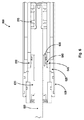
図6は、本発明の例示的な一実施形態に係る減衰調節のために用いられるシリンダ端630上にテーパ状溝(端溝)640を有するエネルギー吸収装置600の概略断面図である。シリンダ端630上のこのような溝640はショックチューブ610の壁を通したオリフィスパターン(図示なし)との組み合わせであるか、単独で存在するかの何れかである。シリンダ端630を通して存在するオリフィスは、そのサイズ及び流量特性からショックチューブ610の壁を通して存在するオリフィスと比較してユニークな減衰特性が得られ、ダッシュポット減衰と、衝撃速度のほぼ直線的な力に比例した減衰力及び衝撃力を送達する可能性とを含む。
FIG. 6 is a schematic cross-sectional view of an
例えば、上記で開示された実施形態の何れかにおいて、エネルギー吸収装置は外部シリンダ605の基端にシリンダ端630と、シリンダ端630の外表面上に端溝640と、シリンダ端630に第一オリフィス635と、ショックチューブ610に第二オリフィス645とを含んでもよい。端溝640はシリンダ端630の外表面上の第一の位置から開始されるが、これはシリンダ端630の外表面内へ向かう第一深度を形成する。端溝640はシリンダ端630の周囲の第二の位置で終了するが、これはシリンダ端630の外表面内へ向かう第二深度を形成する。端溝640の第二深度は端溝640の第一深度よりも浅く、端溝640の深度は端溝640の第一深度から端溝640の第二深度へとテーパ状になる。(シリンダ端の)第一オリフィス635はショックチューブ610の内部と端溝640とに流体連通し、且つ、ピストンのヘッド部615が外部シリンダ605の基端に向かって移動する時にショックチューブ610の内部から端溝640へと流体が流れることを許容する。(ショックチューブの)第二オリフィス645は端溝640とアキュムレータ625とに流体連通し、且つ、ピストンのヘッド部615が外部シリンダ605の基端に向かって移動する時に端溝640からアキュムレータ625へと流体が流れることを許容する。ショックチューブ610と外部シリンダ605との間の相対的な回転によって、ショックチューブ610から(シリンダ端の)第一オリフィス635と、端溝640と、(ショックチューブの)第二オリフィス645とを通したアキュムレータ625への流体の流量を調節可能に変化させるため、端溝640のどの部分を(ショックチューブの)第二オリフィス645と接続するかを変化させる。このような回転によって、エネルギー吸収装置の減衰を変化させる。
For example, in any of the embodiments disclosed above, the energy absorbing device may include a
シリンダ端630の外表面上に存在する端溝の代わりに、端溝をショックチューブ610の内表面上、又はショックチューブ610の外表面に配置することができる。また、端溝はアキュムレータ625に対して装置の反対側の端部(例えば、図6に示す実施形態の遠位端部)に配置してもよく、いくつかの実施形態において、アキュムレータ領域625への流路を提供するため、ショックチューブ610の外径上に軸方向溝を入れてもよい。
Instead of the end groove present on the outer surface of the
本発明はその例示的な実施形態を参照しながら特に示し、説明されてきたが、添付の特許請求の範囲に包含される発明の範囲から逸脱することなく、形状及び詳細についての様々な変更がなされてもよいことが当業者に理解されるであろう。 Although the invention has been particularly shown and described with reference to exemplary embodiments thereof, various changes in form and detail may be made without departing from the scope of the invention as encompassed by the appended claims. One skilled in the art will understand that this may be done.
Claims (17)
先端と、基端と、内壁とを有する外部シリンダのハウジング部材と、
前記外部シリンダ内に回転可能に取り付けられたショックチューブであって、
内表面と、
外表面と、
前記ショックチューブの長軸に沿って一列に並んだ一群の穴を含み、前記穴の各々は流体が前記穴の中を通過することを許容するように前記ショックチューブの前記内表面から前記ショックチューブの前記外表面へと貫通することと、
前記ショックチューブの前記外表面上にテーパ状溝を含み、前記テーパ状溝は一群の一列に並んだ前記穴にわたる、前記ショックチューブの長軸に沿った長さを有し、前記テーパ状溝は一群の一列に並んだ前記穴の位置から開始され、且つ、前記ショックチューブの前記外表面内へ向かう第一深度を形成することと、前記テーパ状溝は前記ショックチューブの周囲の別の位置で終了し、且つ、前記ショックチューブの前記外表面内へ向かう第二深度を形成することと、前記第二深度は前記第一深度よりも浅く、前記テーパ状溝の深度は前記第一深度から前記第二深度へとテーパ状になることと
を含むショックチューブと、
ヘッド部とロッド部とを含むピストンを含み、前記ヘッド部は前記ショックチューブ内に摺動可能に保持されることと、前記ロッド部は前記ヘッド部から前記外部シリンダの前記基端を通して延び、且つ、移動中に外部本体に係合するように構成されることと、
前記外部シリンダ内に収容されたアキュムレータを含み、前記アキュムレータは前記ピストンの前記ヘッド部が前記外部シリンダの前記先端に向かって移動する時に前記ショックチューブの内部から前記流体を回収することと、
前記外部シリンダの前記内壁に形成された流路を含み、前記流路は前記外部シリンダの長さに沿って延び、且つ、前記アキュムレータと流体連通することと、前記ショックチューブと前記外部シリンダとの間の相対的な回転によって前記ショックチューブから一群の一列に並んだ前記穴と、前記テーパ状溝と、前記流路とを通した前記アキュムレータへの前記流体の流量を調節可能に変化させるため、前記テーパ状溝のどの部分を前記流路と接続するかを変化させることと、前記回転によって前記エネルギー吸収装置の減衰を変化させることと
を含むエネルギー吸収装置。 An energy absorber,
An outer cylinder housing member having a distal end, a proximal end, and an inner wall;
A shock tube rotatably mounted in the outer cylinder,
An inner surface,
An outer surface,
A group of holes aligned along the major axis of the shock tube, each of the holes from the inner surface of the shock tube to allow fluid to pass through the hole; Penetrating into the outer surface of
A taper groove on the outer surface of the shock tube, the taper groove having a length along the major axis of the shock tube across the holes in a group of rows, the taper groove being Starting from the position of the holes in a group and forming a first depth into the outer surface of the shock tube; and the tapered groove at another position around the shock tube; And forming a second depth into the outer surface of the shock tube, the second depth being shallower than the first depth, and the depth of the tapered groove from the first depth to the A shock tube including tapering to a second depth;
A piston including a head portion and a rod portion, wherein the head portion is slidably held in the shock tube; and the rod portion extends from the head portion through the proximal end of the outer cylinder; and Configured to engage the external body during movement;
Including an accumulator housed in the outer cylinder, the accumulator collecting the fluid from the inside of the shock tube when the head portion of the piston moves toward the tip of the outer cylinder;
A flow path formed in the inner wall of the outer cylinder, the flow path extending along a length of the outer cylinder, and in fluid communication with the accumulator; and between the shock tube and the outer cylinder In order to adjustably change the flow rate of the fluid to the accumulator through the holes lined up from the shock tube, the tapered groove, and the flow path by relative rotation between An energy absorbing device comprising: changing which portion of the tapered groove is connected to the flow path; and changing attenuation of the energy absorbing device by the rotation.
前記ショックチューブの長軸に沿って一列に並んだ複数の群の前記穴を含み、各群の一列に並んだ前記穴は前記ショックチューブの周囲の異なる位置に配置されることと、
複数の群の一列に並んだ前記穴に対応する複数の前記テーパ状溝を含み、前記テーパ状溝の各々は対応する一群の一列に並んだ前記穴の位置から開始されることと
をさらに含むエネルギー吸収装置。 The energy absorption device according to claim 1,
Including a plurality of groups of holes arranged in a line along the major axis of the shock tube, wherein the holes arranged in a line in each group are arranged at different positions around the shock tube;
A plurality of tapered grooves corresponding to the holes arranged in a row of a plurality of groups, each of the tapered grooves starting from a position of the holes arranged in a corresponding group of rows. Energy absorber.
複数の群の一列に並んだ前記穴に対応する複数の前記流路を含み、前記流路の各々は前記外部シリンダの前記内壁の周囲の異なる位置に形成されることと
をさらに含むエネルギー吸収装置。 The energy absorbing device according to claim 6,
And a plurality of the flow paths corresponding to the holes arranged in a row, each of the flow paths being formed at different positions around the inner wall of the outer cylinder. .
先端と、基端と、内壁とを有する外部シリンダのハウジング部材と、
前記外部シリンダ内に回転可能に取り付けられたショックチューブであって、
内表面と、
外表面と、
前記ショックチューブの長軸に沿って一列に並んだ一群の穴を含み、前記穴の各々は流体が前記穴の中を通過することを許容するように前記ショックチューブの前記内表面から前記ショックチューブの前記外表面へと貫通することと、
前記ショックチューブの前記外表面上に一群の一列に並んだ前記穴に対応する一群のテーパ状溝を含み、前記テーパ状溝の各々は対応する前記穴の位置から開始され、且つ、前記ショックチューブの前記外表面内へ向かう第一深度を形成することと、前記テーパ状溝の各々は前記ショックチューブの周囲の別の位置で終了し、且つ、前記ショックチューブの前記外表面内へ向かう第二深度を形成することと、前記テーパ状溝の前記第二深度は前記テーパ状溝の前記第一深度よりも浅く、前記テーパ状溝の深度は前記第一深度から前記第二深度へとテーパ状になることと、前記テーパ状溝の各々は対応する前記穴に対して周方向において非対称であることと
を含むショックチューブと、
ヘッド部とロッド部とを含むピストンを含み、前記ヘッド部は前記ショックチューブ内に摺動可能に保持されることと、前記ロッド部は前記ヘッド部から前記外部シリンダの前記基端を通して延び、且つ、移動中に外部本体に係合するように構成されることと、
前記外部シリンダ内に収容されたアキュムレータを含み、前記アキュムレータは前記ピストンの前記ヘッド部が前記外部シリンダの前記先端に向かって移動する時に前記ショックチューブの内部から前記流体を回収することと、
前記外部シリンダの前記内壁に形成された流路を含み、前記流路は前記外部シリンダの長さに沿って延び、且つ、前記アキュムレータと流体連通することと、前記ショックチューブと前記外部シリンダとの間の相対的な回転によって前記ショックチューブから一群の一列に並んだ前記穴と、前記テーパ状溝と、前記流路とを通した前記アキュムレータへの前記流体の流量を調節可能に変化させるため、前記テーパ状溝のどの部分を前記流路と接続するかを変化させることと、前記回転によって前記エネルギー吸収装置の減衰を変化させることと
を含むエネルギー吸収装置。 An energy absorber,
An outer cylinder housing member having a distal end, a proximal end, and an inner wall;
A shock tube rotatably mounted in the outer cylinder,
An inner surface,
An outer surface,
A group of holes aligned along the major axis of the shock tube, each of the holes from the inner surface of the shock tube to allow fluid to pass through the hole; Penetrating into the outer surface of
A group of tapered grooves corresponding to the holes aligned in a row on the outer surface of the shock tube, each of the tapered grooves starting from the position of the corresponding hole, and the shock tube Forming a first depth into the outer surface, and each of the tapered grooves terminates at a different location around the shock tube and second into the outer surface of the shock tube. Forming a depth, and the second depth of the tapered groove is shallower than the first depth of the tapered groove, and the depth of the tapered groove is tapered from the first depth to the second depth. And each of the tapered grooves is asymmetric in the circumferential direction with respect to the corresponding hole,
A piston including a head portion and a rod portion, wherein the head portion is slidably held in the shock tube; and the rod portion extends from the head portion through the proximal end of the outer cylinder; and Configured to engage the external body during movement;
Including an accumulator housed in the outer cylinder, the accumulator collecting the fluid from the inside of the shock tube when the head portion of the piston moves toward the tip of the outer cylinder;
A flow path formed in the inner wall of the outer cylinder, the flow path extending along a length of the outer cylinder, and in fluid communication with the accumulator; and between the shock tube and the outer cylinder In order to adjustably change the flow rate of the fluid to the accumulator through the holes lined up from the shock tube, the tapered groove, and the flow path by relative rotation between An energy absorbing device comprising: changing which portion of the tapered groove is connected to the flow path; and changing attenuation of the energy absorbing device by the rotation.
前記ショックチューブの長軸に沿って一列に並んだ複数の群の前記穴を含み、各群の一列に並んだ前記穴は前記ショックチューブの周囲の異なる位置に配置されることと、
複数の群の一列に並んだ前記穴に対応する複数の群の前記テーパ状溝を含み、各群の前記テーパ状溝は対応する一群の一列に並んだ前記穴の位置から開始されることと
をさらに含むエネルギー吸収装置。 The energy absorbing device according to claim 8 , wherein
Including a plurality of groups of holes arranged in a line along the major axis of the shock tube, wherein the holes arranged in a line in each group are arranged at different positions around the shock tube;
A plurality of groups of the tapered grooves corresponding to the holes arranged in a row of a plurality of groups, each tapered groove of each group starting from a position of the holes arranged in a corresponding group of rows; Further comprising an energy absorbing device.
前記外部シリンダの前記基端にシリンダ端を含むことと、
前記シリンダ端の前記外表面上に端溝を含み、前記端溝は前記シリンダ端の前記外表面上の第一の位置から開始され、且つ、前記シリンダ端の前記外表面内へ向かう端溝第一深度を形成することと、前記端溝は前記シリンダ端の周囲の第二の位置で終了し、且つ、前記シリンダ端の前記外表面内へ向かう端溝第二深度を形成することと、前記端溝第二深度は前記端溝第一深度よりも浅く、前記端溝の深度は前記端溝第一深度から前記端溝第二深度へとテーパ状になることと、
前記シリンダ端に第一オリフィスを含み、前記第一オリフィスは前記ショックチューブの内部と前記端溝とに流体連通し、且つ、前記ピストンの前記ヘッド部が前記外部シリンダの前記基端に向かって移動する時に前記ショックチューブの内部から前記端溝へと前記流体が流れることを許容することと、
前記ショックチューブに第二オリフィスを含み、前記第二オリフィスは前記端溝と前記アキュムレータとに流体連通し、且つ、前記ピストンの前記ヘッド部が前記外部シリンダの前記基端に向かって移動する時に前記端溝から前記アキュムレータへと前記流体が流れることを許容することと、前記ショックチューブと前記外部シリンダとの間の相対的な回転によって前記ショックチューブから前記第一オリフィスと、前記端溝と、前記第二オリフィスとを通した前記アキュムレータへの前記流体の流量を調節可能に変化させるため、前記端溝のどの部分を前記第二オリフィスと接続するかを変化させることと、前記回転によって前記エネルギー吸収装置の減衰を変化させることと
をさらに含むエネルギー吸収装置。 The energy absorbing device according to claim 8 , wherein
Including a cylinder end at the proximal end of the outer cylinder;
An end groove is included on the outer surface of the cylinder end, the end groove starting from a first position on the outer surface of the cylinder end, and an end groove first toward the outer surface of the cylinder end. Forming a depth, the end groove ending in a second position around the cylinder end, and forming an end groove second depth into the outer surface of the cylinder end; The end groove second depth is shallower than the end groove first depth, and the end groove depth is tapered from the end groove first depth to the end groove second depth;
The cylinder end includes a first orifice, the first orifice is in fluid communication with the inside of the shock tube and the end groove, and the head portion of the piston moves toward the base end of the outer cylinder. Allowing the fluid to flow from the inside of the shock tube to the end groove when
The shock tube includes a second orifice, wherein the second orifice is in fluid communication with the end groove and the accumulator, and when the head portion of the piston moves toward the base end of the outer cylinder. Allowing the fluid to flow from an end groove to the accumulator; and by relative rotation between the shock tube and the outer cylinder, the first orifice from the shock tube, the end groove, and the Changing the portion of the end groove connected to the second orifice to adjustably change the flow rate of the fluid through the second orifice to the accumulator; and Changing the attenuation of the device.
先端と、基端と、内壁とを有する外部シリンダのハウジング部材と、
前記外部シリンダ内に回転可能に取り付けられたショックチューブを含み、前記ショックチューブは内表面と、外表面と、前記ショックチューブの長さに沿って配置された複数の群の穴とを含むことと、各群の前記穴は前記ショックチューブの周囲の距離にわたることと、各群の前記穴の各々は前記ショックチューブの周囲の異なる位置に配置されることと、前記穴の各々は流体が前記穴の中を通過することを許容するように前記ショックチューブの前記内表面から前記ショックチューブの前記外表面へと貫通することと、
ヘッド部とロッド部とを含むピストンを含み、前記ヘッド部は前記ショックチューブ内に摺動可能に保持されることと、前記ロッド部は前記ヘッド部から前記外部シリンダの前記基端を通して延び、且つ、移動中に外部本体に係合するように構成されることと、
前記外部シリンダ内に収容されたアキュムレータを含み、前記アキュムレータは前記ピストンの前記ヘッド部が前記外部シリンダの前記先端に向かって移動する時に前記ショックチューブの内部から前記流体を回収することと、
前記外部シリンダの前記内壁に形成された流路を含み、前記流路は前記外部シリンダの長さに沿って延び、且つ、前記アキュムレータと流体連通することと、前記流路は前記穴の複数の群の各々にわたる周方向幅を有することと、前記ショックチューブと前記外部シリンダとの間の相対的な回転によって前記ショックチューブから前記流路とともに整合した前記穴と、前記流路とを通した前記アキュムレータへの前記流体の流量を選択可能に変化させるため、前記穴の群の内のどの穴が前記流路とともに整合するかを変化させることと、前記回転によって前記エネルギー吸収装置の減衰を変化させることと
を含むエネルギー吸収装置。 An energy absorber,
An outer cylinder housing member having a distal end, a proximal end, and an inner wall;
A shock tube rotatably mounted within the outer cylinder, the shock tube including an inner surface, an outer surface, and a plurality of groups of holes disposed along the length of the shock tube; The holes in each group span a distance around the shock tube; each of the holes in each group is located at a different location around the shock tube; Penetrating from the inner surface of the shock tube to the outer surface of the shock tube to allow passage through
A piston including a head portion and a rod portion, wherein the head portion is slidably held in the shock tube; and the rod portion extends from the head portion through the proximal end of the outer cylinder; and Configured to engage the external body during movement;
Including an accumulator housed in the outer cylinder, the accumulator collecting the fluid from the inside of the shock tube when the head portion of the piston moves toward the tip of the outer cylinder;
A flow path formed in the inner wall of the outer cylinder, the flow path extending along a length of the outer cylinder, and in fluid communication with the accumulator; and the flow path is a plurality of holes. Having a circumferential width across each of the groups; and through the holes, the holes aligned with the flow path from the shock tube by relative rotation between the shock tube and the outer cylinder, and the flow path. To selectably change the flow rate of the fluid to the accumulator, changing which hole in the group of holes aligns with the flow path and changing the attenuation of the energy absorber by the rotation. And an energy absorber.
Applications Claiming Priority (9)
| Application Number | Priority Date | Filing Date | Title |
|---|---|---|---|
| US201361755051P | 2013-01-22 | 2013-01-22 | |
| US61/755,051 | 2013-01-22 | ||
| US201361827900P | 2013-05-28 | 2013-05-28 | |
| US61/827,900 | 2013-05-28 | ||
| US201361861115P | 2013-08-01 | 2013-08-01 | |
| US61/861,115 | 2013-08-01 | ||
| US14/159,135 | 2014-01-20 | ||
| US14/159,135 US9133902B2 (en) | 2013-01-22 | 2014-01-20 | Shock absorber with variable damping profile |
| PCT/US2014/012246 WO2014116557A1 (en) | 2013-01-22 | 2014-01-21 | Shock absorber with variable damping profile |
Publications (3)
| Publication Number | Publication Date |
|---|---|
| JP2016504551A JP2016504551A (en) | 2016-02-12 |
| JP2016504551A5 JP2016504551A5 (en) | 2017-02-23 |
| JP6416123B2 true JP6416123B2 (en) | 2018-10-31 |
Family
ID=51206862
Family Applications (1)
| Application Number | Title | Priority Date | Filing Date |
|---|---|---|---|
| JP2015555209A Active JP6416123B2 (en) | 2013-01-22 | 2014-01-21 | Shock absorber with variable damping profile |
Country Status (5)
| Country | Link |
|---|---|
| US (1) | US9133902B2 (en) |
| EP (1) | EP2951459B1 (en) |
| JP (1) | JP6416123B2 (en) |
| CA (1) | CA2898851C (en) |
| WO (1) | WO2014116557A1 (en) |
Families Citing this family (24)
| Publication number | Priority date | Publication date | Assignee | Title |
|---|---|---|---|---|
| US8616351B2 (en) | 2009-10-06 | 2013-12-31 | Tenneco Automotive Operating Company Inc. | Damper with digital valve |
| US9884533B2 (en) | 2013-02-28 | 2018-02-06 | Tenneco Automotive Operating Company Inc. | Autonomous control damper |
| US9217483B2 (en) | 2013-02-28 | 2015-12-22 | Tenneco Automotive Operating Company Inc. | Valve switching controls for adjustable damper |
| US9399383B2 (en) | 2013-02-28 | 2016-07-26 | Tenneco Automotive Operating Company Inc. | Damper with integrated electronics |
| US9879748B2 (en) | 2013-03-15 | 2018-01-30 | Tenneco Automotive Operating Company Inc. | Two position valve with face seal and pressure relief port |
| US9163691B2 (en) | 2013-03-15 | 2015-10-20 | Tenneco Automotive Operating Company Inc. | Rod guide arrangement for electronically controlled valve applications |
| US9879746B2 (en) | 2013-03-15 | 2018-01-30 | Tenneco Automotive Operating Company Inc. | Rod guide system and method with multiple solenoid valve cartridges and multiple pressure regulated valve assemblies |
| US9404551B2 (en) | 2013-03-15 | 2016-08-02 | Tenneco Automotive Operating Company Inc. | Rod guide assembly with multi-piece valve assembly |
| JP2016130543A (en) * | 2015-01-13 | 2016-07-21 | 株式会社ショーワ | Pressure buffering device |
| DE112016000579B4 (en) * | 2015-02-03 | 2024-03-28 | Tenneco Automotive Operating Company Inc. | SECONDARY DAMPING ARRANGEMENT FOR A SHOCK ABSORBER |
| CN107429774B (en) | 2015-02-06 | 2019-09-27 | 天纳克汽车营运公司 | Secondary damper assembly for damper |
| WO2016149654A1 (en) * | 2015-03-19 | 2016-09-22 | Kynetec Corporation | Recoil shock absorber for long barrel firearms |
| CN104930017B (en) * | 2015-06-29 | 2017-01-11 | 中国科学院广州能源研究所 | Hydraulic device capable of adjusting buffer energy on two ends |
| FR3046824A1 (en) * | 2016-01-18 | 2017-07-21 | Hydraulique Pb | PROGRESSIVE END-OF-STROKE RETARDER AND PROGRESSIVE STARTING START DEVICE FOR HYDRAULIC CYLINDER |
| JP2017172777A (en) * | 2016-03-25 | 2017-09-28 | 株式会社ショーワ | Air spring structure |
| US10006739B2 (en) | 2016-06-08 | 2018-06-26 | Outdoor Sport Innovations, Llc | Firearm recoil absorber |
| CN110088498B (en) * | 2016-12-26 | 2021-01-15 | 日立汽车系统株式会社 | Cylinder device |
| US10479160B2 (en) | 2017-06-06 | 2019-11-19 | Tenneco Automotive Operating Company Inc. | Damper with printed circuit board carrier |
| US10588233B2 (en) | 2017-06-06 | 2020-03-10 | Tenneco Automotive Operating Company Inc. | Damper with printed circuit board carrier |
| DE102017212021A1 (en) * | 2017-07-13 | 2019-01-17 | Siemens Aktiengesellschaft | Arrangement and method for damping switching movements in high-voltage circuit breakers |
| US11199237B2 (en) * | 2018-08-08 | 2021-12-14 | Raptor Performance Shocks, LLC | Internal bypass shock absorber |
| EP3809012A1 (en) * | 2019-10-18 | 2021-04-21 | Öhlins Racing AB | Front fork position-dependent damping for bicycles and motorcycles |
| CN110921458B (en) * | 2019-12-16 | 2021-08-20 | 安徽金晥泵业科技股份有限公司 | Snub type hydraulic buffer |
| DE102021117898A1 (en) * | 2021-07-12 | 2023-01-12 | Stabilus Gmbh | Fluid damper for modulating a restraining force of a seat belt |
Family Cites Families (13)
| Publication number | Priority date | Publication date | Assignee | Title |
|---|---|---|---|---|
| JPS4842267A (en) * | 1971-10-06 | 1973-06-20 | ||
| US3840097A (en) | 1973-01-22 | 1974-10-08 | Hennells W Co Inc | Adjustable shock absorber |
| US4059175A (en) * | 1975-05-06 | 1977-11-22 | Dressell Jr Richard G | Linear force shock absorber |
| US4026533A (en) * | 1975-08-29 | 1977-05-31 | Hennells Ransom J | Shock absorber with conical control elements |
| US4071122A (en) * | 1976-04-21 | 1978-01-31 | Efdyn Corporation | Adjustable shock absorber |
| JPS5528191U (en) * | 1978-08-15 | 1980-02-23 | ||
| JPS6131558Y2 (en) * | 1981-04-10 | 1986-09-13 | ||
| US4690255A (en) * | 1986-03-10 | 1987-09-01 | Enertrols, Inc. | Compact shock absorber |
| US5598904A (en) * | 1995-06-05 | 1997-02-04 | Enidine, Inc. | Adjustable energy absorption device |
| US6065573A (en) * | 1998-09-04 | 2000-05-23 | Enidine, Inc. | Adjustable energy absorption device with break-off adjustment knob |
| FR2806770B1 (en) * | 2000-03-24 | 2002-08-23 | Jean Perret Ets | HYDRAULIC SHOCK ABSORBER WITH DAMPING TYPE ADJUSTMENT |
| US6883650B2 (en) | 2002-11-15 | 2005-04-26 | Arvinmeritor Technology, Llc. | Adjustable shock absorber |
| US6974002B2 (en) * | 2003-03-20 | 2005-12-13 | Ace Controls, Inc. | Adjustable shock absorber |
-
2014
- 2014-01-20 US US14/159,135 patent/US9133902B2/en active Active
- 2014-01-21 EP EP14703695.8A patent/EP2951459B1/en active Active
- 2014-01-21 WO PCT/US2014/012246 patent/WO2014116557A1/en active Application Filing
- 2014-01-21 JP JP2015555209A patent/JP6416123B2/en active Active
- 2014-01-21 CA CA2898851A patent/CA2898851C/en active Active
Also Published As
| Publication number | Publication date |
|---|---|
| US20140202808A1 (en) | 2014-07-24 |
| US9133902B2 (en) | 2015-09-15 |
| EP2951459A1 (en) | 2015-12-09 |
| EP2951459B1 (en) | 2020-05-06 |
| WO2014116557A1 (en) | 2014-07-31 |
| CA2898851A1 (en) | 2014-07-31 |
| CA2898851C (en) | 2020-04-14 |
| JP2016504551A (en) | 2016-02-12 |
Similar Documents
| Publication | Publication Date | Title |
|---|---|---|
| JP6416123B2 (en) | Shock absorber with variable damping profile | |
| JP2016504551A5 (en) | ||
| TWI356135B (en) | Shock absorber | |
| JP6259722B2 (en) | shock absorber | |
| EP3220079B1 (en) | Electronic expansion valve | |
| JP2017517683A (en) | Frequency dependent damping valve device | |
| CN109114106A (en) | Bearing damp device element, the bearing for being equipped with it and compressor element and manufacturing method | |
| US9731305B2 (en) | Nozzle apparatus and method | |
| JP4884782B2 (en) | shock absorber | |
| KR100877613B1 (en) | Shock absorber | |
| WO2013077849A1 (en) | Nozzle apparatus and method | |
| JP6198926B1 (en) | Hydraulic shock absorber | |
| EP2721307A1 (en) | Device for damping of a piston inside a cylinder housing | |
| US20090008196A1 (en) | Multistage Adjusting Device | |
| US20040045612A1 (en) | Throttle device for high fluid pressures | |
| CN101251195A (en) | Rotating regulation type throttling valve | |
| EP1756465B1 (en) | A hydraulic restrictor | |
| JP6224638B2 (en) | Damping force adjustment device | |
| JP5647183B2 (en) | Hydraulic valves and hydraulic dampers | |
| JP6626336B2 (en) | shock absorber | |
| RU2467224C1 (en) | Hydraulic damping double-acting device | |
| RU2794000C1 (en) | Double-acting hydraulic damper | |
| CN108980257B (en) | Buffer device | |
| RU2017138559A (en) | REDUCING NOISE DIFFUSER THROTTLE WITH CHEVRON | |
| JP2009103283A (en) | Variable damping valve |
Legal Events
| Date | Code | Title | Description |
|---|---|---|---|
| A521 | Written amendment |
Free format text: JAPANESE INTERMEDIATE CODE: A523 Effective date: 20170116 |
|
| A621 | Written request for application examination |
Free format text: JAPANESE INTERMEDIATE CODE: A621 Effective date: 20170116 |
|
| A977 | Report on retrieval |
Free format text: JAPANESE INTERMEDIATE CODE: A971007 Effective date: 20171019 |
|
| A131 | Notification of reasons for refusal |
Free format text: JAPANESE INTERMEDIATE CODE: A131 Effective date: 20171024 |
|
| A521 | Written amendment |
Free format text: JAPANESE INTERMEDIATE CODE: A523 Effective date: 20180122 |
|
| A131 | Notification of reasons for refusal |
Free format text: JAPANESE INTERMEDIATE CODE: A131 Effective date: 20180313 |
|
| A601 | Written request for extension of time |
Free format text: JAPANESE INTERMEDIATE CODE: A601 Effective date: 20180601 |
|
| A521 | Written amendment |
Free format text: JAPANESE INTERMEDIATE CODE: A523 Effective date: 20180910 |
|
| TRDD | Decision of grant or rejection written | ||
| A01 | Written decision to grant a patent or to grant a registration (utility model) |
Free format text: JAPANESE INTERMEDIATE CODE: A01 Effective date: 20180925 |
|
| A61 | First payment of annual fees (during grant procedure) |
Free format text: JAPANESE INTERMEDIATE CODE: A61 Effective date: 20181003 |
|
| R150 | Certificate of patent or registration of utility model |
Ref document number: 6416123 Country of ref document: JP Free format text: JAPANESE INTERMEDIATE CODE: R150 |
|
| R250 | Receipt of annual fees |
Free format text: JAPANESE INTERMEDIATE CODE: R250 |