JP6415735B2 - Power transmission device - Google Patents
Power transmission device Download PDFInfo
- Publication number
- JP6415735B2 JP6415735B2 JP2017538730A JP2017538730A JP6415735B2 JP 6415735 B2 JP6415735 B2 JP 6415735B2 JP 2017538730 A JP2017538730 A JP 2017538730A JP 2017538730 A JP2017538730 A JP 2017538730A JP 6415735 B2 JP6415735 B2 JP 6415735B2
- Authority
- JP
- Japan
- Prior art keywords
- gear
- driven
- bevel gear
- power transmission
- transmission device
- Prior art date
- Legal status (The legal status is an assumption and is not a legal conclusion. Google has not performed a legal analysis and makes no representation as to the accuracy of the status listed.)
- Active
Links
Images


Classifications
-
- F—MECHANICAL ENGINEERING; LIGHTING; HEATING; WEAPONS; BLASTING
- F16—ENGINEERING ELEMENTS AND UNITS; GENERAL MEASURES FOR PRODUCING AND MAINTAINING EFFECTIVE FUNCTIONING OF MACHINES OR INSTALLATIONS; THERMAL INSULATION IN GENERAL
- F16H—GEARING
- F16H19/00—Gearings comprising essentially only toothed gears or friction members and not capable of conveying indefinitely-continuing rotary motion
- F16H19/02—Gearings comprising essentially only toothed gears or friction members and not capable of conveying indefinitely-continuing rotary motion for interconverting rotary or oscillating motion and reciprocating motion
- F16H19/04—Gearings comprising essentially only toothed gears or friction members and not capable of conveying indefinitely-continuing rotary motion for interconverting rotary or oscillating motion and reciprocating motion comprising a rack
-
- F—MECHANICAL ENGINEERING; LIGHTING; HEATING; WEAPONS; BLASTING
- F16—ENGINEERING ELEMENTS AND UNITS; GENERAL MEASURES FOR PRODUCING AND MAINTAINING EFFECTIVE FUNCTIONING OF MACHINES OR INSTALLATIONS; THERMAL INSULATION IN GENERAL
- F16H—GEARING
- F16H1/00—Toothed gearings for conveying rotary motion
- F16H1/02—Toothed gearings for conveying rotary motion without gears having orbital motion
- F16H1/20—Toothed gearings for conveying rotary motion without gears having orbital motion involving more than two intermeshing members
- F16H1/22—Toothed gearings for conveying rotary motion without gears having orbital motion involving more than two intermeshing members with a plurality of driving or driven shafts; with arrangements for dividing torque between two or more intermediate shafts
- F16H1/222—Toothed gearings for conveying rotary motion without gears having orbital motion involving more than two intermeshing members with a plurality of driving or driven shafts; with arrangements for dividing torque between two or more intermediate shafts with non-parallel axes
-
- F—MECHANICAL ENGINEERING; LIGHTING; HEATING; WEAPONS; BLASTING
- F16—ENGINEERING ELEMENTS AND UNITS; GENERAL MEASURES FOR PRODUCING AND MAINTAINING EFFECTIVE FUNCTIONING OF MACHINES OR INSTALLATIONS; THERMAL INSULATION IN GENERAL
- F16H—GEARING
- F16H1/00—Toothed gearings for conveying rotary motion
- F16H1/02—Toothed gearings for conveying rotary motion without gears having orbital motion
- F16H1/04—Toothed gearings for conveying rotary motion without gears having orbital motion involving only two intermeshing members
- F16H1/12—Toothed gearings for conveying rotary motion without gears having orbital motion involving only two intermeshing members with non-parallel axes
- F16H1/14—Toothed gearings for conveying rotary motion without gears having orbital motion involving only two intermeshing members with non-parallel axes comprising conical gears only
-
- F—MECHANICAL ENGINEERING; LIGHTING; HEATING; WEAPONS; BLASTING
- F16—ENGINEERING ELEMENTS AND UNITS; GENERAL MEASURES FOR PRODUCING AND MAINTAINING EFFECTIVE FUNCTIONING OF MACHINES OR INSTALLATIONS; THERMAL INSULATION IN GENERAL
- F16H—GEARING
- F16H1/00—Toothed gearings for conveying rotary motion
- F16H1/28—Toothed gearings for conveying rotary motion with gears having orbital motion
- F16H1/32—Toothed gearings for conveying rotary motion with gears having orbital motion in which the central axis of the gearing lies inside the periphery of an orbital gear
-
- F—MECHANICAL ENGINEERING; LIGHTING; HEATING; WEAPONS; BLASTING
- F16—ENGINEERING ELEMENTS AND UNITS; GENERAL MEASURES FOR PRODUCING AND MAINTAINING EFFECTIVE FUNCTIONING OF MACHINES OR INSTALLATIONS; THERMAL INSULATION IN GENERAL
- F16H—GEARING
- F16H19/00—Gearings comprising essentially only toothed gears or friction members and not capable of conveying indefinitely-continuing rotary motion
- F16H19/02—Gearings comprising essentially only toothed gears or friction members and not capable of conveying indefinitely-continuing rotary motion for interconverting rotary or oscillating motion and reciprocating motion
- F16H19/04—Gearings comprising essentially only toothed gears or friction members and not capable of conveying indefinitely-continuing rotary motion for interconverting rotary or oscillating motion and reciprocating motion comprising a rack
- F16H19/043—Gearings comprising essentially only toothed gears or friction members and not capable of conveying indefinitely-continuing rotary motion for interconverting rotary or oscillating motion and reciprocating motion comprising a rack for converting reciprocating movement in a continuous rotary movement or vice versa, e.g. by opposite racks engaging intermittently for a part of the stroke
-
- F—MECHANICAL ENGINEERING; LIGHTING; HEATING; WEAPONS; BLASTING
- F16—ENGINEERING ELEMENTS AND UNITS; GENERAL MEASURES FOR PRODUCING AND MAINTAINING EFFECTIVE FUNCTIONING OF MACHINES OR INSTALLATIONS; THERMAL INSULATION IN GENERAL
- F16H—GEARING
- F16H55/00—Elements with teeth or friction surfaces for conveying motion; Worms, pulleys or sheaves for gearing mechanisms
- F16H55/02—Toothed members; Worms
- F16H55/10—Constructively simple tooth shapes, e.g. shaped as pins, as balls
-
- F—MECHANICAL ENGINEERING; LIGHTING; HEATING; WEAPONS; BLASTING
- F16—ENGINEERING ELEMENTS AND UNITS; GENERAL MEASURES FOR PRODUCING AND MAINTAINING EFFECTIVE FUNCTIONING OF MACHINES OR INSTALLATIONS; THERMAL INSULATION IN GENERAL
- F16H—GEARING
- F16H55/00—Elements with teeth or friction surfaces for conveying motion; Worms, pulleys or sheaves for gearing mechanisms
- F16H55/02—Toothed members; Worms
- F16H55/17—Toothed wheels
- F16H55/18—Special devices for taking up backlash
- F16H55/20—Special devices for taking up backlash for bevel gears
-
- F—MECHANICAL ENGINEERING; LIGHTING; HEATING; WEAPONS; BLASTING
- F16—ENGINEERING ELEMENTS AND UNITS; GENERAL MEASURES FOR PRODUCING AND MAINTAINING EFFECTIVE FUNCTIONING OF MACHINES OR INSTALLATIONS; THERMAL INSULATION IN GENERAL
- F16H—GEARING
- F16H57/00—General details of gearing
- F16H57/04—Features relating to lubrication or cooling or heating
- F16H57/042—Guidance of lubricant
- F16H57/043—Guidance of lubricant within rotary parts, e.g. axial channels or radial openings in shafts
-
- F—MECHANICAL ENGINEERING; LIGHTING; HEATING; WEAPONS; BLASTING
- F16—ENGINEERING ELEMENTS AND UNITS; GENERAL MEASURES FOR PRODUCING AND MAINTAINING EFFECTIVE FUNCTIONING OF MACHINES OR INSTALLATIONS; THERMAL INSULATION IN GENERAL
- F16H—GEARING
- F16H1/00—Toothed gearings for conveying rotary motion
- F16H1/02—Toothed gearings for conveying rotary motion without gears having orbital motion
- F16H1/24—Toothed gearings for conveying rotary motion without gears having orbital motion involving gears essentially having intermeshing elements other than involute or cycloidal teeth
-
- F—MECHANICAL ENGINEERING; LIGHTING; HEATING; WEAPONS; BLASTING
- F16—ENGINEERING ELEMENTS AND UNITS; GENERAL MEASURES FOR PRODUCING AND MAINTAINING EFFECTIVE FUNCTIONING OF MACHINES OR INSTALLATIONS; THERMAL INSULATION IN GENERAL
- F16H—GEARING
- F16H1/00—Toothed gearings for conveying rotary motion
- F16H1/28—Toothed gearings for conveying rotary motion with gears having orbital motion
-
- F—MECHANICAL ENGINEERING; LIGHTING; HEATING; WEAPONS; BLASTING
- F16—ENGINEERING ELEMENTS AND UNITS; GENERAL MEASURES FOR PRODUCING AND MAINTAINING EFFECTIVE FUNCTIONING OF MACHINES OR INSTALLATIONS; THERMAL INSULATION IN GENERAL
- F16H—GEARING
- F16H55/00—Elements with teeth or friction surfaces for conveying motion; Worms, pulleys or sheaves for gearing mechanisms
- F16H55/02—Toothed members; Worms
- F16H55/26—Racks
Description
本発明は、動力伝達装置に係り、より詳細には、安定した動作具現が可能でありながらも、全体的な高さが低くなって、インデックスのようにコンパクトな装備にも広く適用可能な動力伝達装置に関する。 The present invention relates to a power transmission device. More specifically, the present invention relates to a power transmission device that can realize stable operation but has a low overall height and can be widely applied to compact equipment such as an index. The present invention relates to a transmission device.
動力伝達装置は、回転運動を直線運動に、または直線運動を回転運動に転換させるラックとピニオン、回転運動のみを伝達するが、回転速度とトルクとを変換させるギア列に大別される。 A power transmission device transmits a rotary motion to a linear motion, or a rack and pinion that converts a linear motion to a rotary motion, and transmits only the rotary motion, but is roughly classified into a gear train that converts a rotational speed and a torque.
通常、動力伝達装置の動力伝達体系は、インボリュート曲線を原理とした歯形が主に使われているが、稀にはサイクロイド曲線を原理とした歯形とピン歯車とを使用する場合もある。 Normally, a tooth profile based on the involute curve is mainly used as the power transmission system of the power transmission device. However, a tooth profile based on the cycloid curve and a pin gear may be used in rare cases.
このような動力伝達装置は、半導体装備、LCD、PDP、OLEDなどの平面ディスプレイ装備などを含めた多様な産業機械などに広く使われている。 Such power transmission devices are widely used in various industrial machines including semiconductor equipment, flat display equipment such as LCD, PDP, and OLED.
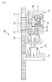
図1は、従来技術による動力伝達装置の使用状態の側面構造図である。 FIG. 1 is a side structural diagram of a power transmission device in use according to the prior art.
図1を参照すれば、従来技術による動力伝達装置1は、例えば、ベースプレート2に対してレール4構造で結合されたスライダー3を直線運動させるために、スライダー3に部分的に結合されうる。
Referring to FIG. 1, the power transmission device 1 according to the related art may be partially coupled to the slider 3 in order to linearly move the slider 3 coupled to the base plate 2 with a
ベースプレート2に対するスライダー3の直線運動のために、スライダー3に連結される動力伝達装置1には、ベースプレート2の領域に位置固定されるラック5と噛み合うピニオン6とが設けられる。 For the linear motion of the slider 3 with respect to the base plate 2, the power transmission device 1 connected to the slider 3 is provided with a pinion 6 that meshes with a rack 5 that is fixed in the region of the base plate 2.
ピニオン6は、動力伝達装置1の外側に延設されるシャフト7の端部に結合されて、図1のような装置の結合時に、ラック5と噛み合う。 The pinion 6 is coupled to an end portion of a shaft 7 extending outside the power transmission device 1 and meshes with the rack 5 when the device as shown in FIG. 1 is coupled.
このような構造によって、動力伝達装置1のモータ8が動作すれば、動力伝達装置1の内蔵部品の相互作用に基づいてシャフト7が回転しながら、ピニオン6が回転する。 With this structure, when the motor 8 of the power transmission device 1 operates, the pinion 6 rotates while the shaft 7 rotates based on the interaction of the built-in components of the power transmission device 1.
この際、ピニオン6は、位置固定されたラック5と噛み合っているために、結果として、回転するピニオン6は、ラック5の長手方向に沿って直線運動することによって、ベースプレート2に対するスライダー3の直線運動が具現される。 At this time, since the pinion 6 meshes with the rack 5 whose position is fixed, as a result, the rotating pinion 6 linearly moves along the longitudinal direction of the rack 5, so that the straight line of the slider 3 with respect to the base plate 2. Movement is embodied.
したがって、スライダー3上に所望の部品や装置を搭載した場合、当該部品や装置が直線運動することができる。 Therefore, when a desired part or device is mounted on the slider 3, the part or device can move linearly.
図1に開示された動力伝達装置1の構造は、現場で最も多く使われている形態であって、ピニオン6の回転軸心に減速機9と共にモータ8が直結される形態なので、動力伝達装置1の全体的な高さ(H1)が高くなるしかない。
The structure of the power transmission device 1 disclosed in FIG. 1 is a form that is most frequently used in the field, and is a form in which the motor 8 is directly connected to the rotational axis of the pinion 6 together with the
従来技術のように、動力伝達装置1の全体的な高さ(H1)が高くなる場合、コンパクトな装備に適用が難しいなど装備適用に多少制約があり得る。 When the overall height (H1) of the power transmission device 1 is increased as in the prior art, there are some restrictions on the application of equipment, such as difficulty in application to compact equipment.
例えば、半導体装備や平面ディスプレイ装備などに広く適用されるインデックス(INDEX)のようなコンパクトな装備には、図1のように、高さ(H1)が高い動力伝達装置1を適用することは困難であるという点を考慮する時、全体的な高さ(H1)を下げながらも、安定した動作具現が可能な動力伝達装置に対する技術開発が必要な実情である。 For example, it is difficult to apply the power transmission device 1 having a high height (H1) as shown in FIG. 1 to a compact equipment such as an index (INDEX) that is widely applied to semiconductor equipment and flat display equipment. Therefore, it is necessary to develop a technology for a power transmission device that can realize stable operation while reducing the overall height (H1).
本発明が解決しようとする技術的な課題は、安定した動作具現が可能でありながらも、全体的な高さが低くなって、インデックスのようにコンパクトな装備にも広く適用可能な動力伝達装置を提供するところにある。 The technical problem to be solved by the present invention is a power transmission device that can realize stable operation but has a low overall height and can be widely applied to compact equipment such as an index. Is to provide.
本発明の一側面によれば、外部ギアに形成される歯形に互いに対応して相対移動する多数の動力伝達ピンを備えるピン歯車と、前記ピン歯車の回転軸心に対して交差する方向に配され、前記ピン歯車の回転のための動力を発生させるモータと、前記ピン歯車と前記モータとの間で前記ピン歯車と前記モータに連結され、前記モータの回転運動を前記ピン歯車の回転運動に伝達する運動伝達ユニットと、を含むことを特徴とする動力伝達装置が提供されうる。 According to one aspect of the present invention, a pin gear having a large number of power transmission pins that move relative to each other in correspondence with the tooth profile formed on the external gear, and a pin gear that is arranged in a direction intersecting the rotational axis of the pin gear. And a motor for generating power for rotation of the pin gear, and the pin gear and the motor are connected to the pin gear and the motor, and the rotational motion of the motor is changed to the rotational motion of the pin gear. And a motion transmission unit for transmitting the power transmission device.
前記運動伝達ユニットは、ユニットハウジングと、前記ユニットハウジングの内部に設けられ、前記モータ側の回転力を減速させて、前記ピン歯車に伝達する内蔵型減速モジュールと、を含みうる。 The motion transmission unit may include a unit housing and a built-in reduction module that is provided inside the unit housing and decelerates the rotational force on the motor side and transmits the reduced rotational force to the pin gear.
前記内蔵型減速モジュールは、前記ピン歯車の回転軸心に対して交差する方向に前記ユニットハウジングに形成される第1貫通部に挿入され、前記モータによって回転する駆動ギアと、前記第1貫通部と連通され、前記第1貫通部と交差する方向に形成される第2貫通部に挿入され、前記駆動ギアと噛合して、前記駆動ギアの回転力を減速させる被動ギアと、を含みうる。 The built-in speed reduction module is inserted into a first penetration part formed in the unit housing in a direction intersecting with the rotation axis of the pin gear, and is rotated by the motor, and the first penetration part And a driven gear which is inserted into a second through part formed in a direction intersecting with the first through part and meshes with the drive gear to reduce the rotational force of the drive gear.
前記駆動ギアは、駆動傘歯車であり、前記被動ギアは、被動傘歯車であり得る。 The driving gear may be a driving bevel gear, and the driven gear may be a driven bevel gear.
前記内蔵型減速モジュールは、前記駆動傘歯車と結合されて、前記駆動傘歯車を固定させる駆動傘歯車固定部材と、前記駆動傘歯車固定部材を前記駆動傘歯車に締結させる第1締結部と、をさらに含みうる。 The built-in reduction module includes a driving bevel gear fixing member that is coupled to the driving bevel gear to fix the driving bevel gear, and a first fastening portion that fastens the driving bevel gear fixing member to the driving bevel gear; May further be included.
前記内蔵型減速モジュールは、前記駆動傘歯車固定部材に離隔配され、前記駆動傘歯車の回転をガイドする多数の駆動側軸受をさらに含みうる。 The built-in reduction module may further include a plurality of drive-side bearings that are spaced apart from the drive bevel gear fixing member and guide the rotation of the drive bevel gear.
前記内蔵型減速モジュールは、前記駆動傘歯車固定部材に接して、前記第1締結部によって前記駆動傘歯車と共に締結され、前記駆動傘歯車の軸方向の遊隔を調節する駆動傘歯車遊隔調節部材をさらに含みうる。 The built-in reduction module is in contact with the driving bevel gear fixing member and is fastened together with the driving bevel gear by the first fastening portion, and adjusts a free movement of the driving bevel gear in the axial direction. A member may further be included.
前記内蔵型減速モジュールは、前記第2貫通部側で前記被動傘歯車と連結され、前記被動傘歯車の回転をガイドする多数の被動側軸受をさらに含みうる。 The built-in reduction module may further include a plurality of driven-side bearings that are coupled to the driven bevel gear on the second penetrating portion side and guide rotation of the driven bevel gear.
前記内蔵型減速モジュールは、前記被動傘歯車と連結され、前記被動傘歯車の組立位置の遊隔を調節する被動傘歯車遊隔調節部材をさらに含みうる。 The built-in speed reduction module may further include a driven bevel gear clearance adjustment member that is connected to the driven bevel gear and adjusts a clearance of an assembly position of the driven bevel gear.
前記内蔵型減速モジュールは、前記被動傘歯車を前記ユニットハウジングに固定させる被動傘歯車固定アダプタをさらに含みうる。 The built-in reduction module may further include a driven bevel gear fixing adapter that fixes the driven bevel gear to the unit housing.
前記内蔵型減速モジュールは、前記第2貫通部の領域で前記被動傘歯車と連結される駆動歯車をさらに含みうる。 The built-in speed reduction module may further include a driving gear connected to the driven bevel gear in the region of the second through portion.
前記内蔵型減速モジュールは、前記駆動歯車の一端部に形成される非円形シャフトが圧入されるシャフト圧入ホールを備えるシャフト圧入部と、前記被動傘歯車に形成される連結ピンが挿入されるピン挿入口と、を備え、前記駆動歯車と連結されて一体型を成す駆動歯車圧入構造体と、前記駆動歯車と前記駆動歯車圧入構造体とを締結させる駆動歯車締結部と、をさらに含みうる。 The built-in reduction module includes a shaft press-fitting portion having a shaft press-fitting hole into which a non-circular shaft formed at one end of the drive gear is press-fitted, and a pin insertion into which a connecting pin formed in the driven bevel gear is inserted. And a drive gear press-fit structure that is connected to the drive gear to form an integral type, and a drive gear fastening portion that fastens the drive gear and the drive gear press-fit structure.
前記内蔵型減速モジュールは、前記駆動歯車と隣接するように前記第2貫通部と平行な方向に前記ユニットハウジングに形成される第3貫通部に結合され、前記駆動歯車からの回転力を前記ピン歯車に伝達する被動歯車をさらに含みうる。 The built-in speed reduction module is coupled to a third through portion formed in the unit housing in a direction parallel to the second through portion so as to be adjacent to the drive gear, and applies rotational force from the drive gear to the pin. It may further include a driven gear that transmits to the gear.
前記内蔵型減速モジュールは、前記被動歯車と結合され、前記被動歯車の回転をガイドする多数の出力側軸受と、前記被動歯車と結合されて、前記被動歯車を予圧する被動歯車予圧部材と、をさらに含みうる。 The built-in reduction module includes a plurality of output-side bearings coupled to the driven gear to guide the rotation of the driven gear, and a driven gear preloading member coupled to the driven gear to preload the driven gear. It may further include.
前記運動伝達ユニットは、前記ユニットハウジングに結合されて、前記被動歯車を保護する被動歯車蓋と、前記被動歯車蓋の反対側で前記ユニットハウジングに結合されて、前記被動歯車の離脱を阻止させる出力端固定プレートと、前記ユニットハウジングに結合されて、前記駆動歯車を保護する駆動歯車蓋と、をさらに含みうる。 The motion transmission unit is coupled to the unit housing to protect the driven gear, and the output is coupled to the unit housing on the opposite side of the driven gear lid to prevent the driven gear from being detached. An end fixing plate and a drive gear lid coupled to the unit housing and protecting the drive gear may be further included.
前記第1貫通部側に結合され、前記モータと前記駆動ギアとを連結させるモータ連結部をさらに含みうる。 A motor coupling unit coupled to the first penetration unit side and coupling the motor and the driving gear may be further included.
前記モータ連結部は、前記モータが装着されるモータ装着ブロックと、前記モータ装着ブロックに結合されて、前記モータをクランピングさせるモータクランプと、前記ユニットハウジングの第1貫通部に結合される入力軸構造体と、前記入力軸構造体と前記モータ装着ブロックとに連結されて、前記モータの回転力を前記駆動ギアに伝達する入力軸固定アダプタと、前記ユニットハウジングに向けた前記入力軸固定アダプタの前側に配される入力側オイルシールと、を含みうる。 The motor connecting portion includes a motor mounting block on which the motor is mounted, a motor clamp coupled to the motor mounting block to clamp the motor, and an input shaft coupled to the first through portion of the unit housing. A structure, an input shaft fixing adapter connected to the input shaft structure and the motor mounting block to transmit the rotational force of the motor to the drive gear, and the input shaft fixing adapter facing the unit housing. And an input side oil seal disposed on the front side.
前記ユニットハウジングには、少なくとも1つの組立基準整列部がさらに形成されうる。 The unit housing may further include at least one assembly reference alignment part.
前記外部ギアは、ラック、外歯車または内歯車のうち何れか1つであり得る。 The external gear may be any one of a rack, an external gear, and an internal gear.
本発明によれば、安定した動作具現が可能でありながらも、全体的な高さが低くなって、インデックスのようにコンパクトな装備にも広く適用可能である。 According to the present invention, while stable operation can be realized, the overall height is low, and it can be widely applied to compact equipment such as an index.
本発明と本発明の動作上の利点及び本発明の実施によって達成される目的を十分に理解するためには、本発明の望ましい実施形態を例示する添付図面及び添付図面に記載の内容を参照しなければならない。 For a full understanding of the invention, its operational advantages, and the objectives achieved by the practice of the invention, reference should be made to the accompanying drawings that illustrate preferred embodiments of the invention and the contents described in the accompanying drawings. There must be.
以下、添付図面を参照して、本発明の望ましい実施形態を説明することによって、本発明を詳しく説明する。各図面に付された同じ参照符号は、同じ部材を示す。 Hereinafter, exemplary embodiments of the present invention will be described in detail with reference to the accompanying drawings. The same reference numerals in each drawing denote the same members.
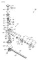
図2は、本発明の一実施形態による動力伝達装置がラックに結合された状態の斜視図であり、図3及び図4は、それぞれ図2を他の角度で示す図面であり、図5は、図2の正面図であり、図6は、図5のA−A線に沿って見た断面図であり、図7は、図5のB−B線に沿って見た断面図であり、図8及び図9は、それぞれ図3及び図4の要部拡大図であり、図10及び図11は、それぞれ図8及び図9の分解斜視図であり、図12及び図13は、それぞれ図10及び図11の要部拡大図であり、図14は、本発明の一実施形態による動力伝達装置が外歯車に結合された状態の斜視図であり、図15は、本発明の一実施形態による動力伝達装置が内歯車に結合された状態の斜視図である。 2 is a perspective view showing a state in which a power transmission device according to an embodiment of the present invention is coupled to a rack. FIGS. 3 and 4 are views showing FIG. 2 at other angles, respectively. 2 is a front view of FIG. 2, FIG. 6 is a cross-sectional view taken along line AA of FIG. 5, and FIG. 7 is a cross-sectional view taken along line BB of FIG. 8 and 9 are enlarged views of main parts of FIGS. 3 and 4, respectively. FIGS. 10 and 11 are exploded perspective views of FIGS. 8 and 9, respectively. FIGS. 10 and FIG. 11 are enlarged views of main parts, FIG. 14 is a perspective view of a state where a power transmission device according to an embodiment of the present invention is coupled to an external gear, and FIG. 15 is an embodiment of the present invention. It is a perspective view in the state where the power transmission device by a form was combined with an internal gear.
図2ないし図13を参照すれば、本実施形態による動力伝達装置100は、安定した動作具現が可能でありながらも、全体的な高さ(H2、図5を参照)が、図1の既存の動力伝達装置1の高さ(H1)よりも遥かに低くなって、インデックスのようにコンパクトな装備にも広く適用可能にしたものであって、外部ギアとしてのラック110と相互作用するピン歯車115と、ピン歯車115の回転のための動力を発生させるモータ(M)と、モータ(M)の回転運動をピン歯車115の回転運動に伝達する運動伝達ユニット120と、を含む。
2 to 13, the
本実施形態において、ラック110は、直線状の棒状のギアであって、ピン歯車115との相互作用に起因して直線運動することができる。例えば、ピン歯車115がその場で回転する場合、ラック110は、直線運動することができる。
In the present embodiment, the
参考までに、本実施形態の場合、外部ギアとしてラック110を開示しているが、外部ギアは、図14に示された外歯車110aや、あるいは図15に示された内歯車110bにもなりうる。
For reference, in the case of the present embodiment, the
例えば、図2のように、外部ギアがラック110である場合には、本実施形態による動力伝達装置100が駆動される時、ラック110が直線運動することができる。そして、図14及び図15のように、外部ギアが外歯車110aあるいは内歯車110bである場合には、本実施形態による動力伝達装置100が駆動される時、外歯車110aあるいは内歯車110bが回転運動させうる。
For example, as shown in FIG. 2, when the external gear is a
ラック110の一側には、ラック歯形111が形成される。ラック歯形111は、ラック110の一側でラック110の長手方向に沿って連続して均等に形成される。ラック110に形成されるラック歯形111は、トロコイド(trochoid)歯形、サイクロイド(cycloid)歯形及びインボリュート(involute)歯形のうちから選択される何れか1つの歯形で適用可能である。
A
ラック110が直線運動を行うように、ピン歯車115は、ラック110と結合されて、その場で回転運動を行う。
The
図9にさらに詳しく示したように、ピン歯車115は、互いに離隔して平行に配されるピン歯車本体117の間に円周方向に沿って多数の動力伝達ピン116が連結される構造を有する。
As shown in more detail in FIG. 9, the
動力伝達ピン116の間隔は、ラック110に形成されるラック歯形111に対応しうる。ピン歯車115に対する細部構造は、本出願人によって既出願されて登録された多数の文献を参照する。
The distance between the power transmission pins 116 may correspond to the
一方、図5に示したように、本実施形態による動力伝達装置100に適用されるモータ(M)は、図1に示された従来の動力伝達装置1とは異なって、ピン歯車115の回転軸心に対して交差する方向に配され、その位置でピン歯車115の回転のための動力を発生させる。
On the other hand, as shown in FIG. 5, the motor (M) applied to the
すなわち、本実施形態の場合、以前のように、ピン歯車115の回転軸心にモータ(M)が直結される形態ではなく、ピン歯車115の回転軸心に対して交差するように横にぶら下がって結合される形態、言い換えれば、ラック110の長手方向と平行にモータ(M)が連結される構造を有する。したがって、動力伝達装置100の全体的な高さ(H2、図2を参照)が、図1の既存の動力伝達装置1の高さ(H1)よりも遥かに低くなって、インデックスのようにコンパクトな装備にも広く適用可能となる。
That is, in the case of the present embodiment, the motor (M) is not directly connected to the rotational axis of the
一方、運動伝達ユニット120は、ピン歯車115とモータ(M)との間でピン歯車115とモータ(M)に連結され、モータ(M)の回転運動を前記ピン歯車115の回転運動に伝達する役割を果たす。
Meanwhile, the
本実施形態において、運動伝達ユニット120は、ユニットハウジング121と、ユニットハウジング121の内部に設けられ、モータ(M)側の回転力を減速させてピン歯車115に伝達する内蔵型減速モジュール125と、を含む。
In the present embodiment, the
ユニットハウジング121は、運動伝達ユニット120の外観構造物である。ユニットハウジング121内に多数の部品の組合わせからなって内蔵型減速モジュール125が有機的なメカニズムを有し、配列及び連結されなければならないために、ユニットハウジング121は、内部が空き金属構造物で製作することができる。
The
このようなユニットハウジング121には、図12及び図13に詳しく示したように、側面に第1ないし第3貫通部121a〜121cが形成される。第1ないし第3貫通部121a〜121cは、ユニットハウジング121の内部で互いに連通されうる。
As shown in detail in FIGS. 12 and 13, the
第1ないし第3貫通部121a〜121cを通じてユニットハウジング121内に内蔵型減速モジュール125がコンパクトに結合される。
A built-in
このように、内蔵型減速モジュール125がユニットハウジング121内に最適化状態で設けられることによって、モータ(M)のサイド搭載が可能となり、これにより、動力伝達装置100の全体的な高さ(H2)を減らせて、インデックスのようにコンパクトな装備にも広く適用可能となる。
As described above, the built-in
参考までに、図6及び図7のように、ユニットハウジング121内に設けられて、互いに連結される多数の部品のうち、駆動歯車蓋155、被動歯車蓋164、出力端固定プレート165などのカバー構造物を除き、残りの部品は、内蔵型減速モジュール125に該当するので、以下の説明では、内蔵型減速モジュール125を別途に区別しないようにする。
For reference, as shown in FIG. 6 and FIG. 7, covers such as a
内蔵型減速モジュール125についての説明に先立って、ユニットハウジング121の第1ないし第3貫通部121a〜121cに装着される代表的な部品についてしばらく言及すれば、下記の通りである。
Prior to the description of the built-in
第1貫通部121aには、ユニットハウジング121の外部に結合されるモータ(M)からの回転動力を受けて駆動する駆動ギア131と、それに付属する部品が順次に結合される。
A
第1貫通部121aに交差して配される第2貫通部121bには、駆動ギア131と噛合して、モータ(M)側の回転力を減速させる被動ギア132と、被動ギア132に連結される駆動歯車151、そして、これらに付属する部品が結合される。
The second penetrating
そして、第3貫通部121cには、駆動歯車151と噛み合って回転する被動歯車161と、それに付属する部品が結合される。被動歯車161は、最終的にピン歯車115に連結されることによって、ピン歯車115を回転させる。
And the driven
結果として、モータ(M)からの回転力は、駆動ギア131、被動ギア132、駆動歯車151、被動歯車161及びピン歯車115に伝達されて、ピン歯車115が回転するようにする。
As a result, the rotational force from the motor (M) is transmitted to the
一方、前述したように、ユニットハウジング121は、運動伝達ユニット120の外観構造物をなす。
On the other hand, as described above, the
ユニットハウジング121の一側面には、組立基準整列部122が形成される。組立基準整列部122には、組立基準を形成する別途の治具(図示せず)が装着され、このような治具を通じて動力伝達装置100を部品別に組み立てるための組立基準を形成しうる。すなわち、組立基準整列部122に装着される治具を通じて、本実施形態による動力伝達装置100を部品別に組み立てる時、ラック110との組立距離、相対位置またはモータ(M)などの組立軸線を整列するための基準を形成しうる。
An assembly
本実施形態において、組立基準整列部122は、互いに交差するように多数個設けられ、溝の形態を有しうる。しかし、組立基準整列部122は、突起の形態にもなりうる。
In the present embodiment, a plurality of assembly
ユニットハウジング121の一側には、モータ連結部170が設けられる。モータ連結部170は、ラック110の長手方向に沿って配されるモータ(M、図5を参照)を第1貫通部121a側に結合される駆動ギア131と連結させる役割を果たす。
A
このようなモータ連結部170は、モータ(M)が装着されるモータ装着ブロック171と、モータ装着ブロック171に結合されて、モータ(M)をクランピングさせるモータクランプ172と、ユニットハウジング121の第1貫通部121aに結合される入力軸構造体173と、入力軸構造体173とモータ装着ブロック171とを連結させる入力軸固定アダプタ174と、を含む。
Such a
ほとんどのモータ(M)が断面四角形状をなすために、本実施形態において、モータ装着ブロック171も、モータ(M)の形状に対応するように四角のブロック構造をなす。しかし、本発明の権利範囲が、これに限定されるものではない。すなわち、モータ装着ブロック171が、必ずしも四角のブロック構造を成す必要はなく、円形であるか、それともその他の多角のブロック構造を有しても良い。
Since most motors (M) have a quadrangular cross section, in this embodiment, the
モータクランプ172は、モータ装着ブロック171の内側クランプ収容部171aに挿入された状態でモータ(M)を堅固にクランピングする。
The
入力軸構造体173は、ユニットハウジング121の第1貫通部121aの入口に結合される構造物である。多数のボルト(B1)によって入力軸構造体173は、ユニットハウジング121の第1貫通部121aの入口に結合されうる。この際、入力軸構造体173の軸受支持具173aは、第1貫通部121a内に挿入され、残りのボディー173bが、ユニットハウジング121の外側に突出する。軸受支持具173aの内側には、機密保持のためにOリング(O−Ring、R1)が結合されうる。
The
入力軸固定アダプタ174は、入力軸構造体173とモータ装着ブロック171に連結される構造物であって、実質的には、モータ(M)の回転力を駆動ギア131に伝達する役割を果たす。したがって、入力軸固定アダプタ174は、駆動側軸受135と連結されうる。
The input
入力軸固定アダプタ174と駆動側軸受135とが連結される時、これらの間のオイルが漏れないように、ユニットハウジング121に向けた前記入力軸固定アダプタ174の前側には、入力側オイルシール175が結合される。
When the input
一方、本実施形態による動力伝達装置100には、内蔵型減速モジュール125の一部品として、駆動ギア131と、駆動ギア131と噛合して、駆動ギア131の回転力を減速させる被動ギア132と、が設けられる。
On the other hand, in the
前述したように、駆動ギア131は、モータ(M)によって回転する部分であって、ユニットハウジング121の第1貫通部121a内に配され、被動ギア132は、ユニットハウジング121の第2貫通部121b内に配されて、駆動ギア131と噛合する。
As described above, the
このような駆動ギア131と被動ギア132とを適用するに当って、ウォームとウォームホイールとを使用することもあるが、本実施形態の場合、傘歯車を適用している。
In applying the
以下、説明の便宜上、駆動ギア131と被動ギア132とを駆動傘歯車131と被動傘歯車132として説明する。混沌を防ぐために、駆動ギア131と駆動傘歯車131、そして、被動ギア132及び被動傘歯車132に同じ参照符号を付与する。
Hereinafter, for convenience of explanation, the
図12及び図13に詳しく示されたように、駆動傘歯車131と被動傘歯車132とのサイズが異なる。すなわち、被動傘歯車132よりも駆動傘歯車131のサイズ、すなわち、ギア数が遥かに少ない。したがって、駆動傘歯車131が1回回転しても、駆動歯車151と連結される被動傘歯車132は1回回転しないために、減速比を具現させうる。
As shown in detail in FIGS. 12 and 13, the
駆動傘歯車131がユニットハウジング121の第1貫通部121a内に結合されるように、駆動傘歯車固定部材133と、第1締結部134と、が設けられる。
A driving bevel
駆動傘歯車固定部材133は、駆動傘歯車131が空回りしないように駆動傘歯車131を固定させる役割を果たす。このために、駆動傘歯車131には、キーブロック131aが形成され、駆動傘歯車固定部材133は、キーブロック131aが挿入されるキー溝133aが形成される。
The driving bevel
第1締結部134は、駆動傘歯車固定部材133を駆動傘歯車131に締結させる役割を果たす。第1締結部134は、ヘッドが外側に突出しない皿頭ボルトであり得る。
The
駆動傘歯車131の軸方向に沿って駆動傘歯車131の円滑な回転動作をガイドする手段として、多数の駆動側軸受135が設けられる。この際、駆動側軸受135は、単列アンギュラ玉軸受であり得る。
A number of drive-
駆動側軸受135を含んで駆動傘歯車131を組み立てる時、駆動傘歯車131が軸方向に押されれば、駆動側軸受135の遊隔が大きくなるしかないために、このような遊隔を無くすために、遊隔調節部材136が設けられる。
When assembling the
言い換えれば、遊隔調節部材136は、駆動傘歯車固定部材133に接して第1締結部134によって駆動傘歯車131と共に締結され、駆動傘歯車131の軸方向の遊隔を調節する役割を果たす。
In other words, the
遊隔調節部材136は、リング(ring)タイプの構造物として適用可能であるが、遊隔程度によって適切な厚さが選択されうる。
The
前述した駆動傘歯車131がユニットハウジング121内で被動傘歯車132と相互作用するために、被動傘歯車132が第2貫通部121b内に挿入されて、駆動傘歯車131と噛合する。
Since the driving
被動傘歯車132の周辺にも被動傘歯車132と連結されて、被動傘歯車132の回転をガイドする多数の被動側軸受141が設けられる。被動側軸受141は、前述した駆動側軸受135とは異なって、単列深溝玉軸受として適用可能である。
A number of driven-
被動傘歯車132がユニットハウジング121に固定されるように、ユニットハウジング121には、被動傘歯車固定アダプタ143が設けられる。
A driven bevel
被動傘歯車固定アダプタ143は、被動側軸受141を支持する軸受支持具143aと、軸受支持具143aと連結されるアダプタブロック143bと、を含む。軸受支持具143aの内側には、Oリング(R2)が結合されうる。
The driven bevel gear fixed
被動側軸受141を含んで被動傘歯車132をユニットハウジング121の第2貫通部121b内に挿入して駆動傘歯車131と組み立てる時、部品の公差上あるいは組み立て公差上の組立位置に遊隔が発生しうるが、このような遊隔を無くすために、被動傘歯車遊隔調整部材142が設けられる。言い換えれば、被動傘歯車遊隔調整部材142は、被動傘歯車132と連結され、被動傘歯車132の組立位置の遊隔を調節する役割を果たす。
When the driven
被動傘歯車遊隔調整部材142が被動傘歯車132と連結されるように、被動傘歯車132には、多数の連結ピン132aが設けられ、被動傘歯車遊隔調整部材142には、連結ピン132aが挿入される第1ピン挿入口142aが形成される。
The driven
一方、内蔵型減速モジュール125の一部品として、駆動歯車151と、被動歯車161と、が設けられ、これらは、ユニットハウジング121内で隣となった部品とコンパクトに結合される。
On the other hand, a
前にもしばらく言及したように、駆動歯車151は、被動傘歯車132と連結される。そして、被動歯車161は、駆動歯車151とピン歯車115とを連結する。
As mentioned before for a while, the
駆動歯車151について先に説明すれば、駆動歯車151は、被動傘歯車132と同様にユニットハウジング121の第2貫通部121bの領域で被動傘歯車132と連結される。
The
駆動歯車151の一側には、ユニットハウジング121に結合されて駆動歯車151を支持する駆動歯車支持部158が設けられる。
On one side of the
駆動歯車151が被動傘歯車132と連結されるために、駆動歯車151は、被動傘歯車132と同回転しうる。
Since the
この際、駆動歯車151と被動傘歯車132は、直結されず、駆動歯車圧入構造体152を介して連結される。
At this time, the
駆動歯車圧入構造体152は、図11に拡大示したように、駆動歯車151の一端部に形成される非円形シャフト151a(図11を参照)が圧入されるシャフト圧入ホール152aを備えるシャフト圧入部152bと、被動傘歯車132に形成される連結ピン132aが挿入される第2ピン挿入口152cと、を含む。
The drive gear press-
駆動歯車151の非円形シャフト151aは、被動傘歯車132の内部中央ホール132b(図13を参照)を通過して、その上部に配される駆動歯車圧入構造体152のシャフト圧入部152bのシャフト圧入ホール152aに圧入されうる。この際、圧入のみでは結合が解除されることもあるために、駆動歯車締結部153が設けられて、駆動歯車151と駆動歯車圧入構造体152とを締結させることができる。駆動歯車締結部153は、ワッシャー153aと、ワッシャー153aを通じて駆動歯車151に締結される第2締結部153bとしてのボルトと、を含みうる。
The
そして、駆動歯車151と駆動歯車圧入構造体152とが締結される時、被動傘歯車132に形成される連結ピン132aは、被動傘歯車遊隔調整部材142に形成される第1ピン挿入口142aを通過して駆動歯車圧入構造体152の第2ピン挿入口152cに挿入されうる。
When the
ユニットハウジング121には、第2貫通部121bの領域に駆動歯車151を保護する駆動歯車蓋155が結合される。内部のメンテナンスのために、駆動歯車蓋155は、ボルトによってユニットハウジング121から着脱されうる。
A
次いで、被動歯車161は、駆動歯車151と隣接するようにユニットハウジング121の第3貫通部121cに結合される。
Next, the driven
被動歯車161は、モータ(M)、駆動傘歯車131、被動傘歯車132及び駆動歯車151から伝達される回転力をピン歯車115に伝達する。したがって、被動歯車161は、ユニットハウジング121内で駆動歯車151と噛合する。
The driven
被動歯車161にピン歯車115が連結されるために、被動歯車161とピン歯車115には、相互連結のための連結ホール(C1、C2、図10及び図11を参照)が形成される。連結ホール(C1、C2)には、図示していないピンが結合されて被動歯車161とピン歯車115とを互いに連結させる。
Since the
このような被動歯車161の周辺には、被動歯車161の回転をガイドする多数の出力側軸受162が設けられる。出力側軸受162は、単列アンギュラ玉軸受として適用可能である。
A number of
そして、被動歯車161が回転する時、被動歯車161に予圧をかけるための手段として、被動歯車予圧部材163が被動歯車161に連結される。被動歯車161に被動歯車予圧部材163が連結されるために、被動歯車161の端部には、多数の予圧ホール161aが形成され、被動歯車予圧部材163には、予圧ホール161aに結合される多数の予圧突起163aが設けられる。被動歯車161の下部には、出力側オイルシール167が結合される。
When the driven
被動歯車161が結合される第3貫通部121cの領域のユニットハウジング121には、被動歯車161を保護する被動歯車蓋164が結合される。
A driven
そして、被動歯車蓋164の反対側には、ユニットハウジング121に結合されて被動歯車161の離脱を阻止させる出力端固定プレート165が結合される。
An output
内部のメンテナンスのために、被動歯車蓋164と出力端固定プレート165は、ボルトによって着脱されうる。
For internal maintenance, the driven
このような構成によって、モータ(M)が動作すれば、モータ(M)からの回転力が駆動ギア131、被動ギア132、駆動歯車151、被動歯車161及びピン歯車115に渡されて、ピン歯車115が回転し、これにより、ラック110がピン歯車115との相互作用に起因して運動することができる。
With this configuration, when the motor (M) operates, the rotational force from the motor (M) is passed to the
このような構造と作用とを有する本実施形態の動力伝達装置100によれば、安定した動作具現が可能でありながらも、特に、全体的な高さ(H2)が低くなって、インデックスのようにコンパクトな装備にも広く適用可能となる。
According to the
このように、本発明は、記載の実施形態に限定されるものではなく、本発明の思想及び範囲を外れずに多様な修正及び変形できるということは、当業者に自明である。したがって、そのような修正例や変形例は、本発明の特許請求の範囲に属するものと言わなければならない。 Thus, it is obvious to those skilled in the art that the present invention is not limited to the described embodiments, and various modifications and changes can be made without departing from the spirit and scope of the present invention. Therefore, it should be said that such modifications and variations belong to the scope of the claims of the present invention.
本発明の動力伝達装置は、回転運動または直線運動を要する各種工作機械を含めて産業用機械装置、半導体あるいは平面ディスプレイ製造設備、そして、各種物流移送設備などに用いられうる。 The power transmission device of the present invention can be used in industrial machine devices, semiconductor or flat display manufacturing facilities, various logistics transfer facilities, and the like, including various machine tools that require rotational motion or linear motion.
Claims (17)
前記ピン歯車の回転軸心に対して交差する方向に配され、前記ピン歯車の回転のための動力を発生させるモータと、
前記ピン歯車と前記モータとの間で前記ピン歯車と前記モータに連結され、前記モータの回転運動を前記ピン歯車の回転運動に伝達する運動伝達ユニットと、
を含み、
前記運動伝達ユニットは、
ユニットハウジングと、
前記ユニットハウジングの内部に設けられ、前記モータ側の回転力を減速させて、前記ピン歯車に伝達する内蔵型減速モジュールと、
を含み、
前記内蔵型減速モジュールは、
前記ピン歯車の回転軸心に対して交差する方向に前記ユニットハウジングに形成される第1貫通部に挿入され、前記モータによって回転する駆動ギアと、
前記第1貫通部と連通され、前記第1貫通部と交差する方向に形成される第2貫通部に挿入され、前記駆動ギアと噛合して、前記駆動ギアの回転力を減速させる被動ギアと、
を含むことを特徴とする動力伝達装置。 A pin gear comprising a number of power transmission pins that move relative to each other in correspondence with the tooth profile formed on the external gear;
A motor that is arranged in a direction intersecting with the rotational axis of the pin gear and generates power for rotation of the pin gear;
A motion transmission unit coupled to the pin gear and the motor between the pin gear and the motor, and transmitting the rotational motion of the motor to the rotational motion of the pin gear;
Including
The motion transmission unit is
A unit housing;
A built-in reduction module that is provided inside the unit housing and decelerates the rotational force on the motor side and transmits it to the pin gear
Including
The built-in deceleration module is
A drive gear that is inserted into a first through portion formed in the unit housing in a direction intersecting with the rotation axis of the pin gear and is rotated by the motor;
A driven gear that communicates with the first penetrating part and is inserted into a second penetrating part formed in a direction intersecting the first penetrating part and meshes with the driving gear to reduce the rotational force of the driving gear; ,
A power transmission device comprising:
前記駆動傘歯車と結合されて、前記駆動傘歯車を固定させる駆動傘歯車固定部材と、
前記駆動傘歯車固定部材を前記駆動傘歯車に締結させる第1締結部と、
をさらに含むことを特徴とする請求項2に記載の動力伝達装置。 The built-in deceleration module is
A driving bevel gear fixing member that is coupled to the driving bevel gear and fixes the driving bevel gear;
A first fastening portion for fastening the drive bevel gear fixing member to the drive bevel gear;
The power transmission device according to claim 2 , further comprising:
前記駆動傘歯車固定部材に離隔配され、前記駆動傘歯車の回転をガイドする多数の駆動側軸受をさらに含むことを特徴とする請求項3に記載の動力伝達装置。 The built-in deceleration module is
The power transmission device according to claim 3 , further comprising a plurality of drive-side bearings spaced apart from the drive bevel gear fixing member and guiding rotation of the drive bevel gear.
前記駆動傘歯車固定部材に接して、前記第1締結部によって前記駆動傘歯車と共に締結され、前記駆動傘歯車の軸方向の遊隔を調節する駆動傘歯車遊隔調節部材をさらに含むことを特徴とする請求項3に記載の動力伝達装置。 The built-in deceleration module is
The driving bevel gear fixing member further includes a driving bevel gear looseness adjusting member that is in contact with the driving bevel gear fixing member and is fastened together with the driving bevel gear by the first fastening portion and adjusts an axial clearance of the driving bevel gear. The power transmission device according to claim 3 .
前記第2貫通部側で前記被動傘歯車と連結され、前記被動傘歯車の回転をガイドする多数の被動側軸受をさらに含むことを特徴とする請求項2に記載の動力伝達装置。 The built-in deceleration module is
3. The power transmission device according to claim 2 , further comprising a plurality of driven-side bearings connected to the driven bevel gear on the second penetrating portion side and guiding rotation of the driven bevel gear.
前記被動傘歯車と連結され、前記被動傘歯車の組立位置の遊隔を調節する被動傘歯車遊隔調節部材をさらに含むことを特徴とする請求項6に記載の動力伝達装置。 The built-in deceleration module is
The power transmission device according to claim 6 , further comprising a driven bevel gear clearance adjustment member that is connected to the driven bevel gear and adjusts a clearance of an assembly position of the driven bevel gear.
前記被動傘歯車を前記ユニットハウジングに固定させる被動傘歯車固定アダプタをさらに含むことを特徴とする請求項7に記載の動力伝達装置。 The built-in deceleration module is
The power transmission device according to claim 7 , further comprising a driven bevel gear fixing adapter for fixing the driven bevel gear to the unit housing.
前記第2貫通部の領域で前記被動傘歯車と連結される駆動歯車をさらに含むことを特徴とする請求項2に記載の動力伝達装置。 The built-in deceleration module is
The power transmission device according to claim 2 , further comprising a drive gear connected to the driven bevel gear in a region of the second penetrating portion.
前記駆動歯車の一端部に形成される非円形シャフトが圧入されるシャフト圧入ホールを備えるシャフト圧入部と、前記被動傘歯車に形成される連結ピンが挿入されるピン挿入口と、を備え、前記駆動歯車と連結されて一体型を成す駆動歯車圧入構造体と、
前記駆動歯車と前記駆動歯車圧入構造体とを締結させる駆動歯車締結部と、
をさらに含むことを特徴とする請求項9に記載の動力伝達装置。 The built-in deceleration module is
A shaft press-fit portion having a shaft press-fit hole into which a non-circular shaft formed at one end of the drive gear is press-fitted, and a pin insertion port into which a connecting pin formed in the driven bevel gear is inserted, A drive gear press-fitting structure connected to the drive gear to form an integral type; and
A drive gear fastening portion for fastening the drive gear and the drive gear press-fit structure;
The power transmission device according to claim 9 , further comprising:
前記駆動歯車と隣接するように前記第2貫通部と平行な方向に前記ユニットハウジングに形成される第3貫通部に結合され、前記駆動歯車からの回転力を前記ピン歯車に伝達する被動歯車をさらに含むことを特徴とする請求項9に記載の動力伝達装置。 The built-in deceleration module is
A driven gear that is coupled to a third through portion formed in the unit housing in a direction parallel to the second through portion so as to be adjacent to the drive gear, and transmits a rotational force from the drive gear to the pin gear. The power transmission device according to claim 9 , further comprising:
前記被動歯車と結合され、前記被動歯車の回転をガイドする多数の出力側軸受と、
前記被動歯車と結合されて、前記被動歯車を予圧する被動歯車予圧部材と、
をさらに含むことを特徴とする請求項11に記載の動力伝達装置。 The built-in deceleration module is
A number of output side bearings coupled to the driven gear for guiding rotation of the driven gear;
A driven gear preloading member coupled with the driven gear to preload the driven gear;
The power transmission device according to claim 11 , further comprising:
前記ユニットハウジングに結合されて、前記被動歯車を保護する被動歯車蓋と、
前記被動歯車蓋の反対側で前記ユニットハウジングに結合されて、前記被動歯車の離脱を阻止させる出力端固定プレートと、
前記ユニットハウジングに結合されて、前記駆動歯車を保護する駆動歯車蓋と、
をさらに含むことを特徴とする請求項11に記載の動力伝達装置。 The motion transmission unit is
A driven gear lid coupled to the unit housing to protect the driven gear;
An output end fixing plate coupled to the unit housing on the opposite side of the driven gear lid to prevent the driven gear from being detached;
A drive gear lid coupled to the unit housing to protect the drive gear;
The power transmission device according to claim 11 , further comprising:
前記モータが装着されるモータ装着ブロックと、
前記モータ装着ブロックに結合されて、前記モータをクランピングさせるモータクランプと、
前記ユニットハウジングの第1貫通部に結合される入力軸構造体と、
前記入力軸構造体と前記モータ装着ブロックとに連結されて、前記モータの回転力を前記駆動ギアに伝達する入力軸固定アダプタと、
前記ユニットハウジングに向けた前記入力軸固定アダプタの前側に配される入力側オイルシールと、
を含むことを特徴とする請求項14に記載の動力伝達装置。 The motor connecting portion is
A motor mounting block on which the motor is mounted;
A motor clamp coupled to the motor mounting block for clamping the motor;
An input shaft structure coupled to the first through part of the unit housing;
An input shaft fixing adapter connected to the input shaft structure and the motor mounting block to transmit the rotational force of the motor to the drive gear;
An input-side oil seal disposed on the front side of the input shaft fixing adapter facing the unit housing;
The power transmission device according to claim 14 , comprising:
Applications Claiming Priority (3)
| Application Number | Priority Date | Filing Date | Title |
|---|---|---|---|
| KR10-2015-0009240 | 2015-01-20 | ||
| KR1020150009240A KR101587833B1 (en) | 2015-01-20 | 2015-01-20 | A transmission device for converting a torque |
| PCT/KR2015/011916 WO2016117809A1 (en) | 2015-01-20 | 2015-11-06 | Power transmission device |
Publications (2)
| Publication Number | Publication Date |
|---|---|
| JP2018508720A JP2018508720A (en) | 2018-03-29 |
| JP6415735B2 true JP6415735B2 (en) | 2018-10-31 |
Family
ID=55309074
Family Applications (1)
| Application Number | Title | Priority Date | Filing Date |
|---|---|---|---|
| JP2017538730A Active JP6415735B2 (en) | 2015-01-20 | 2015-11-06 | Power transmission device |
Country Status (6)
| Country | Link |
|---|---|
| US (1) | US10458527B2 (en) |
| EP (1) | EP3249260B1 (en) |
| JP (1) | JP6415735B2 (en) |
| KR (1) | KR101587833B1 (en) |
| CN (1) | CN107208746B (en) |
| WO (1) | WO2016117809A1 (en) |
Families Citing this family (9)
| Publication number | Priority date | Publication date | Assignee | Title |
|---|---|---|---|---|
| US10968678B2 (en) * | 2017-07-03 | 2021-04-06 | Hall Labs Llc | Automated sliding panel mechanism with manual release mechanism |
| CN107882941B (en) * | 2017-11-30 | 2023-12-19 | 中铁宝桥集团有限公司 | Gear rack transmission mechanism suitable for circular motion |
| CN107979226A (en) * | 2017-12-28 | 2018-05-01 | 广东欧珀移动通信有限公司 | A kind of multi output driving device and electronic equipment |
| KR102075980B1 (en) * | 2018-04-13 | 2020-02-12 | 주식회사 세진아이지비 | Difference transmission |
| CN108799432A (en) * | 2018-08-08 | 2018-11-13 | 江苏欧邦电机制造有限公司 | A kind of Linear reducer |
| CN109630634B (en) * | 2019-01-23 | 2020-03-24 | 昆明理工大学 | Rotary reciprocating motion device based on gear meshing turning |
| JP6584045B1 (en) | 2019-06-28 | 2019-10-02 | 加茂精工株式会社 | Pinion and power transmission device |
| CN110962999B (en) * | 2019-12-04 | 2021-12-28 | 江南造船(集团)有限责任公司 | Connecting device and connecting method for underwater joint of water floating platform |
| KR102305262B1 (en) | 2020-01-08 | 2021-09-27 | 주식회사 세진아이지비 | Self-driving car |
Family Cites Families (11)
| Publication number | Priority date | Publication date | Assignee | Title |
|---|---|---|---|---|
| JPH0733358A (en) | 1993-07-20 | 1995-02-03 | Techman:Kk | Lubricating device for cargo elevator |
| JP3133005B2 (en) * | 1996-12-25 | 2001-02-05 | 加茂精工株式会社 | Rotational and linear motion converter |
| KR200155923Y1 (en) | 1997-01-14 | 1999-09-01 | 배진원 | A reduction gear of an automatic operating apparatus for door |
| WO2003076825A2 (en) | 2002-03-05 | 2003-09-18 | Metal Forming & Coining Corporation | Pinion carrier for planetary gear train and method of making same |
| DE102004032442B4 (en) | 2004-07-05 | 2021-06-17 | Bühler AG | traction drive |
| WO2008025140A1 (en) * | 2006-08-28 | 2008-03-06 | Empire Dynamic Structures Ltd. | Motion transfer system |
| DE102009005343A1 (en) * | 2009-01-16 | 2010-07-22 | Sew-Eurodrive Gmbh & Co. Kg | Bevel gear transmission has block-shaped housing with drive side and output side, where ring-shaped reinforcement is equipped in drive side around through-opening |
| KR101009742B1 (en) | 2010-10-29 | 2011-01-19 | 주식회사 세진아이지비 | A transmission device for converting a torque |
| KR101101900B1 (en) * | 2011-04-18 | 2012-01-02 | 주식회사 세진아이지비 | A transmission device for converting a torque |
| KR20120121470A (en) * | 2011-04-27 | 2012-11-06 | 박정용 | Tool unit for gang type of lathe |
| KR101398073B1 (en) * | 2012-10-31 | 2014-05-27 | (주)로보티즈 | Actuator assembly |
-
2015
- 2015-01-20 KR KR1020150009240A patent/KR101587833B1/en active IP Right Grant
- 2015-11-06 JP JP2017538730A patent/JP6415735B2/en active Active
- 2015-11-06 WO PCT/KR2015/011916 patent/WO2016117809A1/en active Application Filing
- 2015-11-06 CN CN201580073980.0A patent/CN107208746B/en active Active
- 2015-11-06 US US15/543,202 patent/US10458527B2/en active Active
- 2015-11-06 EP EP15879063.4A patent/EP3249260B1/en active Active
Also Published As
| Publication number | Publication date |
|---|---|
| EP3249260B1 (en) | 2019-06-19 |
| EP3249260A4 (en) | 2018-03-14 |
| CN107208746B (en) | 2019-06-28 |
| JP2018508720A (en) | 2018-03-29 |
| WO2016117809A1 (en) | 2016-07-28 |
| CN107208746A (en) | 2017-09-26 |
| EP3249260A1 (en) | 2017-11-29 |
| US20180003274A1 (en) | 2018-01-04 |
| KR101587833B1 (en) | 2016-01-22 |
| US10458527B2 (en) | 2019-10-29 |
Similar Documents
| Publication | Publication Date | Title |
|---|---|---|
| JP6415735B2 (en) | Power transmission device | |
| KR101595845B1 (en) | Decelerator | |
| KR101376006B1 (en) | Reduction gear mechanism, and its manufacturing method | |
| EP2149724B1 (en) | Reduction gear device | |
| CN107246461B (en) | Servo steering engine and robot | |
| CN104033542A (en) | Cycloidal-pin wheel decelerating mechanism | |
| KR200450505Y1 (en) | Gear reducer | |
| JP6483862B2 (en) | Inscribed planetary gear reducer | |
| KR101716453B1 (en) | A transmission device for converting a torque | |
| JP2866249B2 (en) | Speed reducer series with internal meshing planetary gear structure | |
| CN108687708B (en) | Impact tool | |
| KR101464000B1 (en) | Spindle appratus for a machine tool | |
| KR200445028Y1 (en) | Multy worm geared speed reducer | |
| KR200494509Y1 (en) | a Rack and roller pinion | |
| KR101761987B1 (en) | Connection between a drive shaft of a motor and a driven shaft of a driven apparatus | |
| CN109844365B (en) | Planetary gear speed reducer for ultra-high speed reduction | |
| WO2013132748A1 (en) | Eccentric oscillation-type gear device | |
| KR101925805B1 (en) | A driving device of the milling turret | |
| JP2008095705A (en) | Parallel axis gear power transmission device | |
| JP2018105373A (en) | Speed reducer, articulation device and robot arm structure | |
| TWI760515B (en) | Speed reducer | |
| KR100633701B1 (en) | Perpendicular power transmission apparatus | |
| KR20190068416A (en) | Gear unit and method of assembling the same | |
| KR20170115948A (en) | Gear apparatus | |
| KR102554086B1 (en) | Actuator |
Legal Events
| Date | Code | Title | Description |
|---|---|---|---|
| A131 | Notification of reasons for refusal |
Free format text: JAPANESE INTERMEDIATE CODE: A131 Effective date: 20180515 |
|
| A521 | Request for written amendment filed |
Free format text: JAPANESE INTERMEDIATE CODE: A523 Effective date: 20180802 |
|
| TRDD | Decision of grant or rejection written | ||
| A01 | Written decision to grant a patent or to grant a registration (utility model) |
Free format text: JAPANESE INTERMEDIATE CODE: A01 Effective date: 20180918 |
|
| A61 | First payment of annual fees (during grant procedure) |
Free format text: JAPANESE INTERMEDIATE CODE: A61 Effective date: 20181002 |
|
| R150 | Certificate of patent or registration of utility model |
Ref document number: 6415735 Country of ref document: JP Free format text: JAPANESE INTERMEDIATE CODE: R150 |
|
| R250 | Receipt of annual fees |
Free format text: JAPANESE INTERMEDIATE CODE: R250 |
|
| R250 | Receipt of annual fees |
Free format text: JAPANESE INTERMEDIATE CODE: R250 |
|
| R250 | Receipt of annual fees |
Free format text: JAPANESE INTERMEDIATE CODE: R250 |