JP6415707B2 - Ratchet tool - Google Patents
Ratchet tool Download PDFInfo
- Publication number
- JP6415707B2 JP6415707B2 JP2017517157A JP2017517157A JP6415707B2 JP 6415707 B2 JP6415707 B2 JP 6415707B2 JP 2017517157 A JP2017517157 A JP 2017517157A JP 2017517157 A JP2017517157 A JP 2017517157A JP 6415707 B2 JP6415707 B2 JP 6415707B2
- Authority
- JP
- Japan
- Prior art keywords
- claw
- ratchet mechanism
- ratchet
- sleeve
- shaft
- Prior art date
- Legal status (The legal status is an assumption and is not a legal conclusion. Google has not performed a legal analysis and makes no representation as to the accuracy of the status listed.)
- Expired - Fee Related
Links
Images


Classifications
-
- B—PERFORMING OPERATIONS; TRANSPORTING
- B25—HAND TOOLS; PORTABLE POWER-DRIVEN TOOLS; MANIPULATORS
- B25B—TOOLS OR BENCH DEVICES NOT OTHERWISE PROVIDED FOR, FOR FASTENING, CONNECTING, DISENGAGING OR HOLDING
- B25B15/00—Screwdrivers
- B25B15/02—Screwdrivers operated by rotating the handle
- B25B15/04—Screwdrivers operated by rotating the handle with ratchet action
-
- B—PERFORMING OPERATIONS; TRANSPORTING
- B25—HAND TOOLS; PORTABLE POWER-DRIVEN TOOLS; MANIPULATORS
- B25B—TOOLS OR BENCH DEVICES NOT OTHERWISE PROVIDED FOR, FOR FASTENING, CONNECTING, DISENGAGING OR HOLDING
- B25B23/00—Details of, or accessories for, spanners, wrenches, screwdrivers
- B25B23/18—Devices for illuminating the head of the screw or the nut
Landscapes
- Engineering & Computer Science (AREA)
- Mechanical Engineering (AREA)
- Details Of Spanners, Wrenches, And Screw Drivers And Accessories (AREA)
Description
[発明の分野]
本発明は手工具、より詳細にはラチェット工具に関する。
[従来技術の説明]
ドライバーは、ねじを締めてねじを所定位置に保持するために使用される工具であり、軸と柄とを有する。一般に従来技術のドライバーは、柄に固定された軸を有する。使用時に、柄を握る手は小さい角度でしか回すことができない。このため、要素を何回も続けて回転させる必要がある場合、手を所定角度だけ逆に回すことができるように、工程中に手を数回止める必要がある。その方法の1つは、手で握っているドライバーを一時的に要素から放して、手を逆向きに回すことができるようにすることである。この場合、再びドライバーを要素に差し向ける必要がある。別の方法は、もう一方の手を使用して柄を握っている手が柄を放して逆向きに回ることができるように助けることである。明らかに、二つの方法とも不便であり、それが作業効率に影響し、ねじ頭も損傷しやすい。
[Field of the Invention]
The present invention relates to hand tools, and more particularly to ratchet tools.
[Description of prior art]
A screwdriver is a tool used to tighten a screw and hold the screw in place, and has a shaft and a handle. Generally, prior art drivers have a shaft fixed to the handle. In use, the hand holding the handle can only be turned at a small angle. For this reason, if it is necessary to rotate the element several times in succession, it is necessary to stop the hand several times during the process so that the hand can be turned backward by a predetermined angle. One way is to temporarily release the driver from the hand so that the hand can be turned in the opposite direction. In this case, it is necessary to send the driver to the element again. Another way is to help the hand holding the handle using the other hand to release the handle and turn in the opposite direction. Obviously, both methods are inconvenient, which affects work efficiency and the screw heads are prone to damage.
上記の欠陥を克服するために、必要に応じて方向性手回しドライバーが製造される。このような手回しドライバーの「方向性」機能とは、柄が一方の方向に回転されたときに、柄が作動軸を一緒に回転させることで要素にトルクを加えることができ、柄が他方の方向に回転されたときに、柄が作動軸に対して相対的に回転されて作動軸が要素上で位置決めされ、それにより柄を手に持ったまま止まることなく連続的に前後に回すことができ、要素を素早くねじ締めすることまたはねじ外しすることという目的が実現され、さらにこの動作が方向可変性であることである。 To overcome the above deficiencies, a directional hand screwdriver is manufactured as needed. The “directional” function of such a hand screwdriver is that when the handle is rotated in one direction, the handle can apply torque to the element by rotating the operating shaft together, and When rotated in the direction, the handle is rotated relative to the operating shaft so that the operating shaft is positioned on the element so that it can be continuously rotated back and forth without holding the handle in the hand. And the purpose of quickly screwing or unscrewing the element is realized, and this action is also variable in direction.
中国特許第ZL201010184827.4号明細書には、柄と軸とを備えるラチェットドライバーが開示されており、該ドライバーでは、柄の前端部に逆向きかつ部分回転可能な2つの爪と、2つの爪の位置状態を制御するためのトグル部品とを有するように配置された爪座を有する。トグル部品には、上記2つの爪にそれぞれ対応する2つのトグルブロックが設けられる。軸の後端部には、ラチェット座に設けられて2つの爪のうちの少なくとも1つと係合する爪スリーブが設けられ、柄に配置可能な制御部材がトグル部品の位置を変更するために設けられる。分析及び実験から、上記のラチェットドライバーに以下の欠点があることが証明されている。 Chinese Patent No. ZL2010101844827.4 discloses a ratchet driver having a handle and a shaft, in which two nails and two claws that are reverse and partially rotatable at the front end of the handle are disclosed. And a toggle part for controlling the position state of the claw seat. The toggle component is provided with two toggle blocks respectively corresponding to the two claws. A claw sleeve provided on the ratchet seat and engaged with at least one of the two claws is provided at the rear end of the shaft, and a control member that can be disposed on the handle is provided to change the position of the toggle part. It is done. Analysis and experiments prove that the ratchet driver has the following drawbacks.
1.爪スリーブの軸穴と軸穴内に向かって前方に延在する爪座の軸部分とが互いに協働するように構成された結果、軸と爪ベース部との協働領域が小さくなり、軸が爪座に対して激しくぐらつき、ねじ締め性能が劣る。 1. As a result that the shaft hole of the claw sleeve and the shaft portion of the claw seat extending forward toward the inside of the shaft hole cooperate with each other, the cooperation area between the shaft and the claw base portion is reduced, The shaft sways violently against the nail seat and the screwing performance is poor.
2.爪と爪スリーブとの間で係合される歯の数が少なく、トルク伝達能力が低い。
3.ラチェットの歯数が少なく、回し戻し中に必要な回転力が大きいため、プレテンション力が小さいドライバーが回されたときに「方向性」特徴が良好に働かない。
2. The number of teeth engaged between the claw and the claw sleeve is small, and the torque transmission capability is low.
3. Since the number of teeth of the ratchet is small and the rotational force required during turning back is large, the “directionality” feature does not work well when a driver with low pretension force is turned.
そのため、軸のぐらつき問題を解決することができ、効率もよいドライバーが望まれている。
加えて、ラチェットドライバーは広く使用されており、弱い照明下又は暗い環境下で使用された場合、通常は追加の照明装置が用いられる。それにより作業が不便になるため、さらなる照明特徴を有するラチェットドライバーが望まれている。
[発明の概要]
本発明の1つの目的は、軸部材がラチェット機構の内部に延在し、かつ単純な構造に設計されて使用が便利な、軸のぐらつきが低減されたラチェット工具を提供することである。
Therefore, there is a demand for an efficient driver that can solve the shaft wobble problem.
In addition, ratchet drivers are widely used, and additional lighting devices are usually used when used in weak or dark environments. As a result, work becomes inconvenient, so a ratchet driver with additional lighting features is desired.
[Summary of Invention]
One object of the present invention is to provide a ratchet tool with reduced shaft wobble, in which the shaft member extends inside the ratchet mechanism and is designed to be simple and convenient to use.
本発明の別の目的は、ラチェット及び爪の歯数を変更することにより、回し戻しの際に大きな回転力が必要とされ、トルク伝達能力が低いという通常のドライバーの問題を解決することである。 Another object of the present invention is to solve the problem of a normal driver that a large rotational force is required for turning back and the torque transmission ability is low by changing the number of teeth of the ratchet and claw. .
本発明の更なる目的は、照明装置を導入することにより、通常のドライバーにない照明特徴を実現することである。
上記の目的を実現するために、本発明は、軸部材と、柄と、ラチェット機構とを備えるラチェット工具を提供し、該ラチェット工具において、柄はラチェット機構に接続され、軸部材はラチェット機構の前端部からラチェット機構の中心軸に沿ってラチェット機構の内部に延在し、ラチェット機構に接続される。
A further object of the present invention is to realize lighting features not found in ordinary drivers by introducing lighting devices.
In order to achieve the above object, the present invention provides a ratchet tool including a shaft member, a handle, and a ratchet mechanism, wherein the handle is connected to the ratchet mechanism, and the shaft member is connected to the ratchet mechanism. The ratchet mechanism extends from the front end along the central axis of the ratchet mechanism and is connected to the ratchet mechanism.
好ましくは、軸部材はラチェット機構の前端部からラチェット機構の中心軸に沿ってラチェット機構の後端部を貫通し、ラチェット機構に接続される。より好ましくは、軸部材はラチェット機構に対して取り外し可能に接続される。さらに、軸部材は柄から離れた側の第1の端部と、柄に隣接する側の第2の端部とを有する。第1の端部又は第2の端部は、ラチェット機構の前端部からラチェット機構の中心軸に沿ってラチェット機構の内部に延在することができ、ラチェット機構に接続される。 Preferably, the shaft member passes through the rear end portion of the ratchet mechanism along the central axis of the ratchet mechanism from the front end portion of the ratchet mechanism, and is connected to the ratchet mechanism. More preferably, the shaft member is detachably connected to the ratchet mechanism. Further, the shaft member has a first end portion on the side away from the handle and a second end portion on the side adjacent to the handle. The first end or the second end can extend from the front end of the ratchet mechanism to the inside of the ratchet mechanism along the central axis of the ratchet mechanism, and is connected to the ratchet mechanism.
さらに、軸部材は、軸と、ラチェット機構の前端部からラチェット機構の中央軸に沿ってラチェット機構の内部に延在し、ラチェット機構に接続される延在部とを備える。
さらに、軸は延在部と一体的に又は延在部から分離して設計される。
Further, the shaft member includes a shaft and an extending portion that extends from the front end portion of the ratchet mechanism along the central axis of the ratchet mechanism to the inside of the ratchet mechanism and is connected to the ratchet mechanism.
Furthermore, the shaft is designed integrally with the extension or separately from the extension.
さらに、ラチェット機構は、中心軸の両側に沿って爪ベース部上に2つの部分回転可能な爪、すなわち第1の爪及び第2の爪を有するように対称的に構成される爪ベース部と、2つの爪の位置状態を制御するための方向切換部材であって、方向切換部材の上に2つの止めブロック、すなわち第1の止めブロック及び第2の止めブロックを、第1の爪及び第2の爪をそれぞれ押すために2つの爪それぞれの外側に有する方向切換部材とを備え、第1及び第2の爪ならびに第1及び第2の止めブロックの外側には爪スリーブが配置され、爪スリーブの内壁が環状に分布する内側爪歯を有し、爪スリーブが第1の爪及び第2の爪の歯と係合可能である。 Furthermore, the ratchet mechanism includes a claw base portion configured symmetrically so as to have two partially rotatable claws on the claw base portion along both sides of the central axis, that is, a first claw and a second claw. A direction switching member for controlling the position state of two claws, wherein two stop blocks, that is, a first stop block and a second stop block are provided on the direction switch member, the first pawl and the first pawl. A direction switching member provided on the outside of each of the two claws for pressing the two claws, and a claw sleeve is disposed on the outside of the first and second claws and the first and second retaining blocks. The inner wall of the sleeve has inner claw teeth distributed in an annular shape, and the claw sleeve is engageable with the teeth of the first claw and the second claw.
さらに、爪スリーブの内側爪歯の数は60より多く、好ましくは72である。第1の爪の歯の数は3より多く、好ましくは5である。第2の爪の歯の数は3より多く、好ましくは5である。 Furthermore, the number of inner claw teeth of the claw sleeve is more than 60, preferably 72. The number of teeth of the first nail is more than 3, preferably 5. The number of teeth of the second nail is more than 3, preferably 5.
さらに、方向切換部材に接続される位置決め装置も爪スリーブの外側に配置され、好ましくは爪スリーブの外側の周囲に配置される環状スリーブである。
さらに、ラチェット工具は、照明装置をさらに備え、位置決め装置は、照明器具が取り付けられるキャビティを有する。照明装置は、電気回路基板と、電気回路基板に搭載された電源とを有する。
Furthermore, the positioning device connected to the direction switching member is also arranged on the outside of the claw sleeve, preferably an annular sleeve arranged around the outside of the claw sleeve.
Furthermore, the ratchet tool further comprises a lighting device, and the positioning device has a cavity in which the lighting fixture is mounted. The lighting device includes an electric circuit board and a power source mounted on the electric circuit board.
ラチェット機構は、2つの端部、すなわち爪スリーブに隣接する側の端部及び爪スリーブから離れた側の別の端部、を有する。前端部とは、爪スリーブに隣接する側の端部を指し、同様に、後端部とは、爪スリーブから離れた側のもう一方の端部を指す。 The ratchet mechanism has two ends: an end adjacent to the claw sleeve and another end away from the claw sleeve. The front end portion refers to the end portion on the side adjacent to the claw sleeve, and similarly, the rear end portion refers to the other end portion on the side away from the claw sleeve.
「ラチェット機構の内部に延在する」には、ラチェット機構の後端部を貫通する場合、及びラチェット機構の後端部を貫通しない場合の2つの場合が含まれる。
本発明の目的、特徴、及び利点を十分に理解できるようするために、本発明の概念、詳細な構造、及び期待される技術的効果に関するさらなる説明を、添付の図面を参照して行う。
“Extending inside the ratchet mechanism” includes two cases of passing through the rear end portion of the ratchet mechanism and not passing through the rear end portion of the ratchet mechanism.
In order that the objectives, features, and advantages of the present invention may be fully understood, further description regarding the concept, detailed structure, and expected technical effects of the present invention will be made with reference to the accompanying drawings.
[好適な実施形態の詳細な説明]
(実施形態1)
図1−15は本発明の好適な実施形態の関連構造概略図である。
[Detailed Description of Preferred Embodiments]
(Embodiment 1)
1-15 is a schematic diagram of the relevant structure of the preferred embodiment of the present invention.
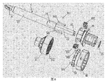
図1−3に示すように、本発明のラチェット工具は、軸部材1と、柄2と、ラチェット機構3とを有する。柄2はラチェット機構3に接続される。軸部材1は、ラチェット機構3の前端部からラチェット機構3の中心軸に沿ってラチェット機構3の内部に延在し、ラチェット機構3に接続される。本実施形態では、軸部材1が、ラチェット機構3の前端部からラチェット機構3の中心軸に沿ってラチェット機構3の後端部を貫通し、ラチェット機構3に接続されることが好ましい。
As illustrated in FIG. 1C, the ratchet tool of the present invention includes a
軸部材1は、さらに軸11と延在部12とを有する。本実施形態では、軸11は延在部12と一体的に設計されており、延在部12は、ラチェット機構3の内部に延在し、ラチェット機構3の前端部からラチェット機構3の中心軸に沿ってラチェット機構3の後端部を貫通し、ラチェット機構3に接続される。軸部材1の構造をより明確に図6に示しており、軸11の後端部には、1つの部分又は軸11の対向する両側に位置する1対の部分(図7に示す)として設計され得るキー溝14が設けられる。キー溝14は、爪スリーブ31の形状に合致し、軸11と爪スリーブ31とを強固に固定するために用いられ、トルク伝達時に軸11が爪スリーブ31に対してぐらつかないようにする。
The
トルクを出力するために、作動部4が柄から離れた側の軸部材1の端部に設けられる。作動部4は具体的には、柄から離れた側の軸部材1の端部に取り付けられる(図1に示す)、スロット付きのトルクス(登録商標)又はヘックスソケットドライバービットなどの様々な型のドライバービットであってもよい。作動部4は様々な型のスリーブであってもよく、スリーブは軸部材1と一体的に設計されてもよく(図8に示す)、様々な型のスリーブを取り付けるために使用可能な接続部材41(図9に示す)を介して軸部材1に接続されてもよい。
In order to output torque, the operating
軸11の直径は、延在部12の直径よりも大きい。延在部12の後端部には軸溝15が設けられ、固定リング13(リテーナリングなど)が軸溝15の形状と合致するように対応して設計される。延在部12が爪ベース部36の穴を貫通する場合には、軸溝15の形状と合致する固定リング13が軸溝内に固着される。軸11の直径が延在部12の直径より大きく、軸溝15と固定リング13とが組み合わされて協働的に使用されるため、爪ベース部36は、軸方向に移動することなく軸部材に強固に固定される。加えて、軸部材1とラチェット機構3とをこのように接続することで、軸部材1と爪ベース部36の穴との間に形状が合致する長い面が生まれ、軸部材1と爪ベース部36との間の接触面積が増すため、ラチェット工具を使用する際における軸11の爪ベース部36に対するぐらつきの問題が解決され、ねじ締め効率が良好になる。
The diameter of the
本実施形態では、柄2から入力されたいずれの方向(時計回り方向又は反時計回り方向)のトルクも軸部材1に伝達され、軸部材1は所定方向(時計回り又は反時計回り)にトルクを出力する。
In the present embodiment, torque in any direction (clockwise direction or counterclockwise direction) input from the
図4−6に示すように、ラチェット機構3は、軸部材1上に配置されて中心軸に沿って軸部材1が貫通する爪ベース部36を備える。爪ベース部36は、爪ベース部上において中央軸の両側に沿って配置される2つの部分回転可能な爪、すなわち第1の爪351及び第2の爪352と、2つの爪の位置状態を制御するための方向切換部材33とを有するように対称的に構成される。方向切換部材33はその上に2つの止めブロック、すなわち第1の止めブロック331及び第2の止めブロック332を有する。第1の止めブロック331は第1の爪351に対応し、第2の止めブロック332は第2の爪352に対応する。爪スリーブ31は、第1及び第2の爪351、352、ならびに第1及び第2の止めブロック331、332の外側に配置される。
As shown in FIG. 4-6, the
爪スリーブ31の内壁には環状に分布する内側爪歯311が設けられる。爪スリーブ31は第1の爪351及び第2の爪352の周りに配置され、その内側爪歯311は第1の爪351及び第2の爪352の歯と係合する。方向切換部材33が接続される位置決め装置32も爪スリーブ31の外側に配置され、方向切換部材33と一体的に接続されることも可能である。位置決め装置32は、具体的には回転スリーブであり、爪スリーブ31の外側の周囲に配置される環状スリーブである。中央位置にあるときの位置決め装置32が図10及び11に示されている。
Inner claw teeth 311 distributed in an annular shape are provided on the inner wall of the
位置決め装置32が回転されると、方向切換部材33がそれに伴って移動し、方向切換部材33上の第1及び第2の止めブロック331、332もそれに伴って移動する。図12及び13に示すように、位置決め装置32が時計回りに回されると、第2の止めブロック332が第2の爪352を押して第2の爪352を爪スリーブ31の内側爪歯311から外し、第1の爪351は爪スリーブ31の内側爪歯311と係合した状態を継続する。このとき、柄を時計回りに回すことにより、爪ベース部36、爪スリーブ31と係合する第1の爪351、及び爪スリーブ31を介して、柄から軸へとトルクを伝達することができる。柄が反時計周りに回されると、爪スリーブ31と係合する第1の爪351は、爪ベース部36によって運ばれて、軸にトルクを伝達することなく爪スリーブ31の内側爪歯311上方をスライドすることができ、柄が回転される。図14及び15に示すように、位置決め装置32が反時計回りに回転されると、第1の止めブロック331が第1の爪351を押して第1の爪351を爪スリーブ31の内側爪歯311から外し、第2の爪352は爪スリーブ31の内側爪歯311と係合した状態を継続する。このとき、柄を反時計回りに回すことにより、爪ベース部36、爪スリーブ31と係合する第2の爪352、及び爪スリーブ31を介して、柄から軸へとトルクを伝達することができる。柄が時計周りに回されると、爪スリーブ31と係合する第2の爪352は、爪ベース部によって運ばれて、軸にトルクを伝達することなく爪スリーブ31の内側爪歯311上方をスライドすることができ、柄が回転される。図中のどの位置まで回転スリーブが回転されようとも、回転スリーブをその位置に配置し、維持することができる。
When the
さらに、2つの爪351、352を開いて爪スリーブに当接させるための第1の弾性部材37が、第1及び第2の爪の間に支持される。方向切換部材33上の第1の止めブロック331が対応する第1の爪351の外側に位置し、方向切換部材33上の第2の止めブロック332が対応する第2の爪352の外側に位置することにより、第1及び第2の爪351、352が確実に爪スリーブ31と係合する。
Further, a first
加えて、第1の爪351が、第1のピン341を介して爪ベース部36に接続され、第2の爪352が、第2のピン342を介して爪ベース部36に接続されることにより、第1及び第2の爪351、352が確実に素早く回転することができ、同時に爪がトルクを伝達するための十分な能力を確実に有する。
In addition, the
図10−15に示すように、回転スリーブの内壁は、第1の位置決め凹部324と、第2の位置決め凹部325と、第3の位置決め凹部326とを有する。爪ベース部36は、その上に位置決めボール321を有するように構成され、位置決めボール321は、第1の位置決め凹部324、第2の位置決め凹部325、及び第3の位置決め凹部326のうちの1つに、第2の弾性部材323により支持されており、それにより柄上での回転スリーブの位置決めが実現される。本構造によれば、回転スリーブが図10及び11に示す状態にあるときに、位置決めボール321は第2の位置決め凹部325内にあり、第1の爪351及び第2の爪352は図11に示す状態にある。回転スリーブが図12及び13に示す状態にあるときに、位置決めボール321は第3の位置決め凹部326内にあり、第1の爪351及び第2の爪352は図13に示す状態にある。回転スリーブが図14及び15に示す状態にあるときに、位置決めボール321は第1の位置決め凹部324内にあり、第1の爪351及び第2の爪352は図15に示す状態にある。
As shown in FIG. 10-15, the inner wall of the rotary sleeve has a
図10及び11に示すように、爪ベース部は凹部361を有し、該凹部361内には方向切換部材33が配置される。回転スリーブと方向切換部材33とがそれらの間の固定具322(ねじなど)によって接続されることにより凹部361内の方向切換部材33が軸方向に移動できないように制限することによる、すなわち回転スリーブが作動位置から離脱することを固定具322により防止することによる、回転スリーブの制限が実現されると同時に、回転スリーブによる方向切換部材33の作動が実現される。
As shown in FIGS. 10 and 11, the claw base portion has a
「方向性」特徴を最適化すべく回し戻しの際に必要な回転力をさらに減少させるために、本発明では爪スリーブ31の内側爪歯311の歯の数がさらに改良される。本実施形態では、内側爪歯311の歯の数は60より多く、好ましくは72以上(例えば72)である。
In order to further reduce the rotational force required for turning back to optimize the “directional” feature, the present invention further improves the number of teeth of the inner claw teeth 311 of the
その一方で、トルク伝達能力を強化するために、本発明では爪スリーブ31と係合する第1及び第2の爪の歯の数を増加させている。本実施形態では、第1及び第2の爪の歯の数が3より多く、好ましくは5以上(例えば5)に設定される。同様に、数が60より多いという前提の下、爪スリーブ31の内側爪歯311の歯の数は、第1及び第2の爪の歯の数に適合するように設定される。
(実施形態2)
本実施形態は実施形態1に類似し、主な違いは軸部材の構造である。
On the other hand, in order to strengthen the torque transmission capability, in the present invention, the number of teeth of the first and second claws engaged with the
(Embodiment 2)
The present embodiment is similar to the first embodiment, and the main difference is the structure of the shaft member.
本実施形態において、軸部材は柄から離れた側の第1の端部と、柄に隣接する側の第2の端部と、第1の端部と第2の端部との間に位置する中央部とを有する。中央部の半径は、中央部から両側に延在する部分の半径より大きい。軸部材の第1の端部がラチェット機構の内部に延在する場合、中央部の半径の方が大きいため、爪スリーブが取り付けられ、軸部材の軸方向の固定を実現することができる。あるいは、軸部材が引き出され、軸部材の第2の端部がラチェット機構の内部に挿入され、爪スリーブが取り付けられると、軸部材の軸方向の固定を同じく実現することができる。 In the present embodiment, the shaft member is positioned between the first end on the side away from the handle, the second end on the side adjacent to the handle, and the first end and the second end. And a central portion. The radius of the central portion is larger than the radius of the portion extending from the central portion to both sides. When the first end portion of the shaft member extends inside the ratchet mechanism, since the radius of the central portion is larger, the claw sleeve is attached, and the shaft member can be fixed in the axial direction. Alternatively, when the shaft member is pulled out, the second end portion of the shaft member is inserted into the ratchet mechanism, and the claw sleeve is attached, the axial fixing of the shaft member can be similarly realized.
軸部材の第1の端部は具体的には、スリーブ、スリーブが取り付けられた接続部材、様々な型のドライバービット(ヘックスソケットブラスドライバービット等)などの作動部であってもよい。軸部材の第2の端部も具体的には、スリーブ、スリーブが取り付けられた接続部材、様々な型のドライバービット(ヘックスソケットブラスドライバービット等)などの作動部であってもよく、実現される第1の端部の特徴と第2の端部の特徴とは同じでないことが好ましい。すなわち、軸部材の第1の端部と第2の端部とは2つの異なる特徴を有することが好ましい。軸部材の第1の端部がラチェット機構内に位置する場合には、ラチェット工具は1つの特徴を有し、軸部材が引き出され、方向を切り換えて使用される場合、すなわち軸部材の第2の端部がラチェット機構内にある場合には、ラチェット工具は別の特徴を有する。軸部材のこのような設計によって、自由な取り外し及び軸部材の両方向での使用が実現され、さらには1つのラチェット工具が2つの異なる特徴を持つことが可能になる。
(実施形態3)
図1、図4、及び図10−21は本発明の別の好適な実施形態の構造概略図である。
Specifically, the first end portion of the shaft member may be an operating portion such as a sleeve, a connecting member to which the sleeve is attached, and various types of driver bits (hex socket brass driver bit or the like). Specifically, the second end portion of the shaft member may be an operating portion such as a sleeve, a connecting member to which the sleeve is attached, and various types of driver bits (hex socket brass driver bits, etc.), and is realized. Preferably, the first end feature and the second end feature are not the same. That is, it is preferable that the first end portion and the second end portion of the shaft member have two different characteristics. When the first end of the shaft member is located in the ratchet mechanism, the ratchet tool has one feature, when the shaft member is pulled out and used in a switched direction, i.e. the second of the shaft member. The ratchet tool has another feature when the end of the is in the ratchet mechanism. Such a design of the shaft member allows free removal and use of the shaft member in both directions, and furthermore allows one ratchet tool to have two different features.
(Embodiment 3)
1, 4 and 10-21 are structural schematics of another preferred embodiment of the present invention.
本実施形態は実施形態1に類似し、主な違いは軸部材1の構造である。
図16に示すように、本発明のラチェット工具は、軸部材1と、柄2と、ラチェット機構3とを備える。柄2はラチェット機構3に接続される。軸部材1は、ラチェット機構3の前端部からラチェット機構3の中心軸に沿ってラチェット機構3の内部に延在し、ラチェット機構3に接続される。本実施形態では、軸部材1は、ラチェット機構3の前端部からラチェット機構3の中心軸に沿ってラチェット機構3の後端部を貫通し、ラチェット機構3に接続されることが好ましい。
The present embodiment is similar to the first embodiment, and the main difference is the structure of the
As shown in FIG. 16, the ratchet tool of the present invention includes a
軸部材1はさらに、軸11と延在部12とを有する。本実施形態では、軸11は延在部12から分離して設計されており、延在部12は、ラチェット機構3の内部に延在し、ラチェット機構3の前端部からラチェット機構3の中心軸に沿ってラチェット機構3の後端部を貫通し、ラチェット機構3に接続される。軸部材1の構造をより明確に図18−19に示す。軸11には、爪スリーブ31の形状と合致する六角軸端111が設けられる。六角軸端111は爪スリーブ31を貫通し、軸11と爪スリーブ31とを強固に固定するために用いられ、トルク伝達時に軸11が爪スリーブ31に対してぐらつかないようにする。
The
トルクを出力するために、作動部4が、柄から離れた側の軸部材1の端部に設けられる。作動部4は具体的には、スロット付きのトルクス又はヘックスソケットドライバービットなどの様々な型のドライバービットであってもよく、ドライバービットは、柄から離れた側の軸部材1の端部に取り付けられる(図16に示す)。作動部4は様々な型のスリーブであってもよく、スリーブは、軸部材1と一体的に設計されてもよく(図20に示す)、様々な型のスリーブを取り付けるために用いることができる接続部材41(図21に示す)を介して軸部材1に接続されてもよい。
In order to output torque, the operating
延在部12の後端部には軸溝15が設けられ、固定リング13(リテーナリングなど)が軸溝15の形状と合致するように対応して設計される。延在部12が爪ベース部36の穴を貫通するときに、延在部12は六角軸端111と密接に接触し、軸溝15の形状と合致する固定リング13が軸溝15内に固着される。六角軸端111と爪スリーブ31とが協働し、軸溝15と固定リング13とが組み合わされて協働的に使用されるため、爪ベース部36は、軸方向に移動することなく軸部材に強固に固定される。加えて、軸部材1とラチェット機構3との軸貫通接続により、軸部材1と爪ベース部36の穴との間に長い形状合致面が生まれ、軸部材1と爪ベース部36との間の接触面積が増すため、ラチェット工具使用時における軸11の爪ベース部36に対するぐらつきの問題が解決され、ねじ締め効率が良好になる。
A
本実施形態では、柄2から入力されたトルクは、どちらの方向(時計回り又は反時計回り)であっても軸部材1に伝達され、軸部材1が所定方向(時計回り又は反時計回り)にトルクを出力する。
In this embodiment, the torque input from the
図4及び図18に示すように、ラチェット機構3は、軸部材1上に配置されるとともに中心軸に沿って軸部材1が貫通する爪ベース部36を備える。爪ベース部36は、中心軸の両側に沿って爪ベース部36上に部分回転可能な2つの爪、すなわち第1の爪351及び第2の爪352と、2つの爪の位置状態を制御するための方向切換部材33であって、2つの止めブロック、すなわち第1の止めブロック331及び第2の止めブロック332を有する方向切換部材33とを有するように対称的に構成される。第1の止めブロック331は第1の爪351に対応し、第2の止めブロック332は第2の爪352に対応する。爪スリーブ31は第1及び第2の爪351、352、ならびに第1及び第2の止めブロック331、332の外側に配置される。
As shown in FIGS. 4 and 18, the
爪スリーブ31の内側壁には、環状に分布する内側爪歯311が設けられる。爪スリーブ31は第1の爪351及び第2の爪352の周りに配置され、その内側爪歯311は第1の爪351及び第2の爪352の歯と係合する。方向切換部材33が接続される位置決め装置32も爪スリーブ31の外側に配置され、方向切換部材33に一体的に接続することも可能である。位置決め装置32は、具体的には回転スリーブであり、爪スリーブ31の外側の周囲に配置される環状スリーブである。中央位置にあるときの位置決め装置32が図10及び11に示されている。
Inner claw teeth 311 distributed annularly are provided on the inner wall of the
位置決め装置32が回転されると、方向切換部材33がそれに伴って移動し、方向切換部材33上の第1及び第2の止めブロック331、332もそれに伴って移動する。図12及び13に表すように、位置決め装置32が時計回りに回されると、第2の止めブロック332が第2の爪352を押して第2の爪352を爪スリーブ31の内側爪歯311から外し、第1の爪351は爪スリーブ31の内側爪歯311と係合した状態を継続する。このとき、柄を時計回りに回すと、爪ベース部36、爪スリーブ31と係合する第1の爪351、及び爪スリーブ31を介して、柄から軸へとトルクを伝達することができる。柄が反時計周りに回されると、爪スリーブ31と係合する第1の爪351は、爪ベース部36によって運ばれて、軸にトルクを伝達することなく爪スリーブ31の内側爪歯311上方でスライドすることができ、柄が回転される。図14及び15に示すように、位置決め装置32が反時計回りに回転されると、第1の止めブロック331が第1の爪351を押して第1の爪351を爪スリーブ31の内側爪歯311から外し、第2の爪352は爪スリーブ31の内側爪歯311と係合した状態を継続する。このとき、柄を反時計回りに回すと、爪ベース部36、爪スリーブ31と係合する第2の爪352、及び爪スリーブ31を介して、柄から軸へとトルクを伝達することができる。柄が時計回りに回されると、爪スリーブ31と係合する第2の爪352は、爪ベース部によって運ばれて、軸にトルクを伝達することなく爪スリーブ31の内側爪歯311上方でスライドすることができ、柄が回転される。図中のどの位置まで回転スリーブが回転されようとも、回転スリーブをその位置に配置し、維持することができる。
When the
さらに、2つの爪351、352を開いて爪スリーブに当接させるための第1の弾性部材37が、第1及び第2の爪の間に支持される。方向切換部材33上の第1の止めブロック331が、対応する第1の爪351の外側に位置し、方向切換部材33上の第2の止めブロック332が、対応する第2の爪352の外側に位置することにより、第1及び第2の爪351、352が確実に爪スリーブ31と係合される。
Further, a first
加えて、第1の爪351が、第1のピン341によって爪ベース部36に接続され、第2の爪352が、第2のピン342によって爪ベース部36に接続されることにより、第1及び第2の爪351、352が確実に素早く回転することができ、同時に爪がトルクを伝達するための十分な能力も確実に有する。
In addition, the
図10−15に示すように、回転スリーブの内壁には、第1の位置決め凹部324と、第2の位置決め凹部325と、第3の位置決め凹部326とが設けられる。爪ベース部36は、その上に位置決めボール321を有するように構成され、位置決めボール321は、第1の位置決め凹部324、第2の位置決め凹部325、及び第3の位置決め凹部326のうちの1つに、第2の弾性部材323によって支持されており、それにより柄上における回転スリーブの位置決めが実現される。本構造によれば、回転スリーブが図10及び11に示す状態にあるときに、位置決めボール321は第2の位置決め凹部325内にあり、第1の爪351及び第2の爪352は、図11に示す状態にある。回転スリーブが図12及び13に示す状態にあるときには、位置決めボール321は第3の位置決め凹部326内にあり、第1の爪351及び第2の爪352は図13に示す状態にある。回転スリーブが図14及び15に示す状態にあるときには、位置決めボール321は第1の位置決め凹部324内にあり、第1の爪351及び第2の爪352は図15に示す状態にある。
As shown in FIG. 10-15, the inner wall of the rotary sleeve is provided with a
図10及び11に示すように、爪ベース部には、方向切換部材33が配置される凹部361が設けられる。回転スリーブと方向切換部材33とがそれらの間の固定具322(ねじなど)を介して接続されることにより、軸方向に移動できないように凹部361内の方向切換部材33を制限することによる、すなわち、固定具322による回転スリーブの作動位置からの離脱を防止することによる、回転スリーブの制限が実現される一方で、回転スリーブによる方向切換部材33の作動が実現される。
As shown in FIGS. 10 and 11, the claw base portion is provided with a
「方向性」特徴を最適化するために回し戻しの際に必要な回転力をさらに減少させるために、本発明では爪スリーブの内側爪歯311の歯の数が改良されている。本実施形態では、内側爪歯311の歯の数は60より多く、好ましくは72以上(例えば72)である。 In order to further reduce the rotational force required for turning back to optimize the “directivity” feature, the present invention improves the number of teeth of the inner claw teeth 311 of the claw sleeve. In the present embodiment, the number of teeth of the inner claw tooth 311 is more than 60, preferably 72 or more (for example, 72).
同時に、トルク伝達能力を強化するために、本発明では、爪スリーブ31と係合する第1及び第2の爪の歯の数を増加させている。本実施形態では、第1及び第2の爪の歯の数が3より多く、好ましくは5以上(例えば5)に設定される。これに対応して、60より多いという前提の下、爪スリーブ31の内側爪歯311の歯の数は第1及び第2の爪の歯の数に適合するように設定される。
(実施形態4)
図7、図10−15、及び図22−25は、本発明のさらなる好適な実施形態の構造概略図である。
At the same time, in order to enhance the torque transmission capability, in the present invention, the number of teeth of the first and second claws engaged with the
(Embodiment 4)
Figures 7, 10-15, and 22-25 are structural schematics of further preferred embodiments of the present invention.
本実施形態は実施形態1に類似し、主な違いは追加された照明装置であることが図から見て取れる。
本実施形態では、実施形態1に基づいて照明装置が加えられている。照明装置の特定の位置を図23に示す。位置決め装置32は、具体的には回転スリーブであり、爪スリーブ31の外側の周囲に配置される環状スリーブである。本実施形態では、位置決め装置32は、照明装置が取り付けられるキャビティ321を有する。図24及び25に示すように、照明装置は、電気回路基板5と、電気回路基板に搭載された電源7とを有する。照明装置が位置決め装置32のキャビティ321内に強固に取り付けられると、透明カバー6が覆い、位置決め装置32に固定される。これにより照明特徴が実現される。
This embodiment is similar to the first embodiment, and it can be seen from the drawing that the main difference is the added lighting device.
In the present embodiment, a lighting device is added based on the first embodiment. A specific position of the lighting device is shown in FIG. The
照明装置を本実施形態に適用することにより、ラチェット回転部品と照明装置との効率的な組み合わせが実現され、本発明のラチェット工具は回転部品の特徴を有するだけでなく、同時に照明の特徴をも有することができる。
(実施形態5)
本実施形態は実施形態2及び3に類似し、主な違いは追加された照明装置である。照明装置は、実施形態4の照明装置と同じである。
By applying the illuminating device to this embodiment, an efficient combination of the ratchet rotating component and the illuminating device is realized, and the ratchet tool of the present invention has not only the characteristics of the rotating component but also the characteristics of the illumination at the same time. Can have.
(Embodiment 5)
This embodiment is similar to
特定の実施形態を参照して上記に本発明を例証した。しかしながら、本発明の概念に基づき、一般的な当業者により多くの改変及び変更をなすことが可能であることは理解されるべきである。ゆえに、当業者が本発明の概念に基づいて論理的分析、推論、又は限られた実験から獲得したいかなる技術的な体系も、特許請求の範囲に規定された本発明の範囲内にある。 The invention has been illustrated above with reference to specific embodiments. However, it should be understood that many modifications and changes can be made by those of ordinary skill in the art based on the concepts of the present invention. Therefore, any technical scheme obtained by a person skilled in the art from logical analysis, reasoning, or limited experimentation based on the inventive concept is within the scope of the invention as defined in the claims.
Claims (15)
前記柄が前記ラチェット機構に接続され、前記軸部材が、前記ラチェット機構の前端部から前記ラチェット機構の中心軸に沿って前記ラチェット機構の内部に延在し、前記ラチェット機構に接続され、
前記ラチェット機構は爪ベース及び爪スリーブを備え、
前記軸部材が軸と延在部とを有し、前記軸が前記延在部と一体的に設計され、前記軸の直径が前記延在部の直径よりも大きく、前記延在部には、固定リングの形状と合致し、前記延在部を前記ラチェット機構に対して軸方向に移動不能にする軸溝が設けられ、前記柄に隣接する側の前記軸の端部は、前記爪スリーブの形状と合致して前記軸と前記爪スリーブとを固定するために用いられる軸端を有し、前記軸端が六角軸端である、ラチェット工具。 A ratchet tool comprising a shaft member, a handle, and a ratchet mechanism,
The handle is connected to the ratchet mechanism, and the shaft member extends from the front end of the ratchet mechanism along the central axis of the ratchet mechanism to the inside of the ratchet mechanism, and is connected to the ratchet mechanism;
The ratchet mechanism includes a claw base and a claw sleeve,
The shaft member has a shaft and an extending portion, the shaft is designed integrally with the extending portion, the diameter of the shaft is larger than the diameter of the extending portion, A shaft groove that matches the shape of the fixing ring and makes the extension portion axially immovable with respect to the ratchet mechanism is provided, and an end portion of the shaft adjacent to the handle is formed on the claw sleeve. A ratchet tool having a shaft end used to fix the shaft and the claw sleeve in conformity with a shape, the shaft end being a hexagonal shaft end .
前記ラチェット機構はさらに、前記2つの爪の位置状態を制御するための方向切換部材を備え、該方向切換部材は、その上に2つの止めブロック、すなわち第1の止めブロック及び第2の止めブロックを、前記第1の爪及び前記第2の爪をそれぞれ押すために前記2つの爪それぞれの外側に有し、
前記第1及び第2の爪ならびに前記第1及び第2の止めブロックの外側には前記爪スリーブが配置され、該爪スリーブの内側壁が環状に分布する内側爪歯を有し、前記爪スリーブが前記第1の爪及び前記第2の爪の歯と係合する、請求項5に記載のラチェット工具。 The claw base portion is symmetrically constructed to have two parts rotatable pawl along both sides of the central axis on the claw base portion, i.e., the first pawl and the second pawl,
The ratchet mechanism further includes a direction switching member for controlling the position state of the two claws, the direction switching member comprises two stop blocks on top of its, that is, the first stop block and a second stop the block, have a first pawl and said second pawl on the outside of each of the two claws to push each
Wherein the outside of the first and second pawl and said first and second stop blocks said pawl sleeve is disposed, an inner pawl teeth of the inner walls of the pawl sleeve is annularly distributed, said pawl sleeve The ratchet tool of claim 5 wherein the engages with teeth of the first and second pawls.
Applications Claiming Priority (1)
| Application Number | Priority Date | Filing Date | Title |
|---|---|---|---|
| PCT/CN2014/079842 WO2015188373A1 (en) | 2014-06-13 | 2014-06-13 | Ratchet tool |
Publications (3)
| Publication Number | Publication Date |
|---|---|
| JP2017518894A JP2017518894A (en) | 2017-07-13 |
| JP2017518894A5 JP2017518894A5 (en) | 2017-08-24 |
| JP6415707B2 true JP6415707B2 (en) | 2018-10-31 |
Family
ID=54832747
Family Applications (1)
| Application Number | Title | Priority Date | Filing Date |
|---|---|---|---|
| JP2017517157A Expired - Fee Related JP6415707B2 (en) | 2014-06-13 | 2014-06-13 | Ratchet tool |
Country Status (6)
| Country | Link |
|---|---|
| US (1) | US9770813B2 (en) |
| EP (1) | EP3156178B1 (en) |
| JP (1) | JP6415707B2 (en) |
| AU (1) | AU2014397458A1 (en) |
| CA (1) | CA2951958C (en) |
| WO (1) | WO2015188373A1 (en) |
Families Citing this family (6)
| Publication number | Priority date | Publication date | Assignee | Title |
|---|---|---|---|---|
| US10556328B2 (en) * | 2016-09-13 | 2020-02-11 | Leon Robert Palmer | Inline screwdriver with hands-free activated dual-drive self-ratcheting mechanism |
| US10668600B1 (en) | 2019-02-06 | 2020-06-02 | Jingrong Ye | Wrench |
| US11235441B2 (en) | 2019-02-06 | 2022-02-01 | Albertson Enterprises, Llc | Wrench |
| US11161222B2 (en) | 2019-02-06 | 2021-11-02 | Weikai Yang | Wrench |
| US11944502B2 (en) | 2020-04-10 | 2024-04-02 | Medartis Ag | Torque limiting ratcheting handle for medical instrument |
| US12023014B2 (en) | 2020-04-10 | 2024-07-02 | Nextremity Solutions, Inc. | Ratcheting handle for medical instrument |
Family Cites Families (37)
| Publication number | Priority date | Publication date | Assignee | Title |
|---|---|---|---|---|
| US2720296A (en) * | 1952-02-28 | 1955-10-11 | Amalite Inc | Ratchet tools |
| US5613585A (en) * | 1995-05-02 | 1997-03-25 | Beere Precision Medical Instruments, Inc. | Ratcheting screwdriver |
| US5806381A (en) * | 1997-03-20 | 1998-09-15 | Lin; Ching Chou | Ratchet screw driver assembly |
| US6047801A (en) * | 1997-12-09 | 2000-04-11 | Liao; Yung-Chuan | Ratchet screwdriver |
| US6082226A (en) * | 1999-06-21 | 2000-07-04 | Lin; Jack | Ratchet tool having a ratchet direction positioning device |
| US6224229B1 (en) * | 1999-08-18 | 2001-05-01 | Ching Chou Lin | Rotatable driving tool having light device |
| US6244139B1 (en) | 2000-06-20 | 2001-06-12 | Daniel Huang | Adjustable shifter for controlling the racing of a slideable ratchet shank |
| US6658970B2 (en) * | 2001-12-14 | 2003-12-09 | Hsuan-Sen Shiao | Ratchet screwdriver |
| US20030126958A1 (en) * | 2002-01-09 | 2003-07-10 | Great Neck Saw Manufacturers, Inc. | Ratchet driver |
| US6925912B2 (en) * | 2002-08-23 | 2005-08-09 | Chin-Tan Huang | Operating device for a screwdriver |
| US7137320B2 (en) * | 2003-02-07 | 2006-11-21 | Easco Hand Tools, Inc. | Ratcheting tool driver |
| US6935211B2 (en) * | 2004-01-20 | 2005-08-30 | Su Shia Chen | Ratchet tool having improved driving shank |
| US7028587B1 (en) * | 2005-07-15 | 2006-04-18 | Shu Chi Chiang | Ratchet tool |
| JP5057738B2 (en) * | 2006-10-02 | 2012-10-24 | 中国電力株式会社 | Driver lighting system |
| US20080266845A1 (en) * | 2007-04-25 | 2008-10-30 | Unity Opto Technology Co., Ltd. | Auxiliary lighting device |
| US20080278930A1 (en) * | 2007-05-09 | 2008-11-13 | Unity Opto Technology Co., Ltd. | Tool structure with illumination |
| US20080278931A1 (en) * | 2007-05-11 | 2008-11-13 | Unity Opto Technology Co., Ltd. | Tool structure with illumination |
| CN100569456C (en) | 2007-05-25 | 2009-12-16 | 王宁生 | Ratchet batch |
| US20090044668A1 (en) * | 2007-08-16 | 2009-02-19 | Shu-Sui Lin | Torque device for use in tools |
| US7748296B2 (en) | 2008-07-24 | 2010-07-06 | Gong Fong Enterprise Co., Ltd. | Ratchet screwdriver with an accelerating structure |
| US7993023B2 (en) * | 2009-09-16 | 2011-08-09 | Chien-Kuo Wang | Hand tool with an illuminating device |
| US8210072B2 (en) * | 2010-02-26 | 2012-07-03 | Suter Robert Lee | Roller bearing ratchet tool |
| CN201816012U (en) | 2010-03-18 | 2011-05-04 | 上海齐迈五金有限公司 | Ratcheting screw driver handle with lamp |
| CN201677279U (en) | 2010-05-27 | 2010-12-22 | 杭州巨星科技股份有限公司 | Screw driver of ratchet wheel |
| CN101890688B (en) | 2010-05-27 | 2012-12-26 | 杭州巨星科技股份有限公司 | Ratchet screw driver |
| US8272298B2 (en) * | 2010-09-08 | 2012-09-25 | Yi-Fu Chen | Steering device for a ratchet screwdriver |
| US8806987B2 (en) * | 2010-09-08 | 2014-08-19 | Yi-Fu Chen | Steering device for a ratchet screwdriver |
| US9028088B2 (en) * | 2010-09-30 | 2015-05-12 | Black & Decker Inc. | Lighted power tool |
| US8544365B2 (en) * | 2011-08-16 | 2013-10-01 | Tzu-Chien Wang | Ratchet tool |
| US9242355B2 (en) * | 2012-04-17 | 2016-01-26 | Black & Decker Inc. | Illuminated power tool |
| DE102012010528B3 (en) * | 2012-05-29 | 2013-07-11 | Jin-Tsai Lai | Ratchet screwdriver with reversing direction |
| US9427861B2 (en) * | 2013-02-28 | 2016-08-30 | Sicom Industries Ltd. | Bit tool having a bit storage member, light assembly for a bit tool and bit tool having a ratcheting handle assembly |
| CN103192337A (en) | 2013-03-07 | 2013-07-10 | 绍兴环洲工具制造有限公司 | Telescopic mounting/dismounting tool |
| US10022846B2 (en) * | 2013-05-27 | 2018-07-17 | Hangzhou Great Star Tools Co., Ltd. | Screwdriver |
| US9162348B2 (en) * | 2013-07-01 | 2015-10-20 | Shih-Chi Ho | Steering and positioning structure of a ratchet screwdriver |
| US20150049467A1 (en) * | 2013-08-19 | 2015-02-19 | Mark R Thompson | Hands-Free Device to Illuminate Work Areas |
| US9278435B2 (en) * | 2013-11-06 | 2016-03-08 | Chiung-Chang Tsai | Ratchet screwdriver |
-
2014
- 2014-06-13 JP JP2017517157A patent/JP6415707B2/en not_active Expired - Fee Related
- 2014-06-13 EP EP14894623.9A patent/EP3156178B1/en active Active
- 2014-06-13 AU AU2014397458A patent/AU2014397458A1/en not_active Abandoned
- 2014-06-13 WO PCT/CN2014/079842 patent/WO2015188373A1/en active Application Filing
- 2014-06-13 US US14/369,795 patent/US9770813B2/en active Active
- 2014-06-13 CA CA2951958A patent/CA2951958C/en not_active Expired - Fee Related
Also Published As
| Publication number | Publication date |
|---|---|
| CA2951958A1 (en) | 2015-12-17 |
| EP3156178A1 (en) | 2017-04-19 |
| CA2951958C (en) | 2021-03-30 |
| AU2014397458A1 (en) | 2017-02-02 |
| JP2017518894A (en) | 2017-07-13 |
| US9770813B2 (en) | 2017-09-26 |
| EP3156178A4 (en) | 2018-01-24 |
| US20170087696A1 (en) | 2017-03-30 |
| WO2015188373A1 (en) | 2015-12-17 |
| EP3156178B1 (en) | 2020-01-01 |
Similar Documents
| Publication | Publication Date | Title |
|---|---|---|
| JP6415707B2 (en) | Ratchet tool | |
| TWI661909B (en) | Penetrating electric ratchet wrench and using method thereof | |
| US7311018B1 (en) | Wrench | |
| US9833883B2 (en) | Bi-directional screwdriver | |
| AU2016101315A4 (en) | Power tool | |
| US7228767B2 (en) | Tool connecting device | |
| US8424421B1 (en) | Jog-shuttle type ratchet wrench | |
| US7069818B1 (en) | Ratchet wrench | |
| US20090217789A1 (en) | Ratchet control structure | |
| KR101475877B1 (en) | Multi directional screwdriver bit adapter | |
| TW201834792A (en) | Hub for ratchet gears | |
| US20130008755A1 (en) | Clutch Capable of Force Transmission in a Selected One of Two Directions | |
| CN105328622B (en) | Ratchet tool | |
| US6550357B1 (en) | Wrench connector | |
| CN104339296B (en) | Ratchet screw driver | |
| EP2727686A1 (en) | Socket wrench | |
| CN204019432U (en) | Ratchet tool | |
| US20150101461A1 (en) | Driving tool combination | |
| CA2984687C (en) | Multi-bit tool | |
| US20150047472A1 (en) | Dual-drive, self-ratcheting, mechanism with multiple input ports | |
| US20170080550A1 (en) | One-way ratchet tool set | |
| JP6461274B2 (en) | Bidirectional wrench | |
| JPH10151575A (en) | Wrench for thumbscrew | |
| JPH081532A (en) | Screw driver | |
| GB2517446A (en) | Multipurpose tool |
Legal Events
| Date | Code | Title | Description |
|---|---|---|---|
| A521 | Request for written amendment filed |
Free format text: JAPANESE INTERMEDIATE CODE: A523 Effective date: 20170608 |
|
| A621 | Written request for application examination |
Free format text: JAPANESE INTERMEDIATE CODE: A621 Effective date: 20170608 |
|
| A977 | Report on retrieval |
Free format text: JAPANESE INTERMEDIATE CODE: A971007 Effective date: 20180409 |
|
| A131 | Notification of reasons for refusal |
Free format text: JAPANESE INTERMEDIATE CODE: A131 Effective date: 20180417 |
|
| A521 | Request for written amendment filed |
Free format text: JAPANESE INTERMEDIATE CODE: A523 Effective date: 20180713 |
|
| TRDD | Decision of grant or rejection written | ||
| A01 | Written decision to grant a patent or to grant a registration (utility model) |
Free format text: JAPANESE INTERMEDIATE CODE: A01 Effective date: 20180904 |
|
| A61 | First payment of annual fees (during grant procedure) |
Free format text: JAPANESE INTERMEDIATE CODE: A61 Effective date: 20181002 |
|
| R150 | Certificate of patent or registration of utility model |
Ref document number: 6415707 Country of ref document: JP Free format text: JAPANESE INTERMEDIATE CODE: R150 |
|
| R250 | Receipt of annual fees |
Free format text: JAPANESE INTERMEDIATE CODE: R250 |
|
| LAPS | Cancellation because of no payment of annual fees |