JP6415195B2 - Drive device - Google Patents
Drive device Download PDFInfo
- Publication number
- JP6415195B2 JP6415195B2 JP2014182054A JP2014182054A JP6415195B2 JP 6415195 B2 JP6415195 B2 JP 6415195B2 JP 2014182054 A JP2014182054 A JP 2014182054A JP 2014182054 A JP2014182054 A JP 2014182054A JP 6415195 B2 JP6415195 B2 JP 6415195B2
- Authority
- JP
- Japan
- Prior art keywords
- vibrator
- friction
- relative movement
- holding member
- contact
- Prior art date
- Legal status (The legal status is an assumption and is not a legal conclusion. Google has not performed a legal analysis and makes no representation as to the accuracy of the status listed.)
- Active
Links
Images


Description
本発明は振動子に超音波振動を発生させることにより駆動力を発生する超音波モータ等の駆動装置に関する。 The present invention relates to a driving device such as an ultrasonic motor that generates a driving force by generating ultrasonic vibration in a vibrator.
従来から、動作音が無く、低速から高速までの駆動が可能であり、高トルク出力などの特徴を活かして、例えば、カメラやレンズの駆動源として超音波モータが採用されている。特許文献1に開示された超音波モータは、振動子が摩擦部材に対して弾性部材によって付勢された状態である、所謂、加圧接触状態で保持されている。その加圧接触状態下で当該振動子に超音波振動が励起されると、振動子の摩擦部材と接している接触部に楕円運動が生じ、振動子が直進駆動される。この際、振動子を加圧または押圧部材は円筒の一部からなる線接触部を有していて、振動子の駆動方向に直交する軸周りに自在に動き振動子に摩擦部材の摩擦接触面に対して垂直に加圧することができる。 Conventionally, there is no operation sound, driving from low speed to high speed is possible, and for example, an ultrasonic motor is used as a drive source for a camera or a lens, taking advantage of features such as high torque output. The ultrasonic motor disclosed in Patent Document 1 is held in a so-called pressure contact state in which the vibrator is biased by an elastic member with respect to the friction member. When ultrasonic vibration is excited in the vibrator under the pressure contact state, elliptical motion is generated in the contact portion in contact with the friction member of the vibrator, and the vibrator is driven straight. At this time, the vibrator is pressed or the pressing member has a line contact portion formed of a part of a cylinder, and freely moves around an axis orthogonal to the driving direction of the vibrator. The pressure can be applied perpendicular to.
特許文献1に開示された超音波モータにおいて振動子は、摩擦部材との接触面を平面で構成しており、構成部品の組み立てや加工による誤差が生じると、摩擦部材の摩擦接触面と振動子の当接面に傾きが生じ、摩擦接触面と振動子当接面が不安定な当接となっていた。 In the ultrasonic motor disclosed in Patent Document 1, the vibrator has a flat contact surface with the friction member, and if an error occurs due to assembly or processing of the component parts, the friction contact surface of the friction member and the vibrator As a result, the friction contact surface and the vibrator contact surface are in an unstable contact.
本発明は、上述の問題に鑑み、振動子に発生する超音波振動による楕円運動により駆動する駆動装置としての超音波モータにおいて、簡単な構成により振動子当接面と摩擦部材を安定して確実に当接させることを目的とする。 In view of the above-described problems, the present invention provides an ultrasonic motor as a driving device that is driven by elliptical motion generated by ultrasonic vibration generated in a vibrator, and the vibrator contact surface and the friction member are stably and reliably provided with a simple configuration. It aims at making it contact.
上記課題を解決するために、本発明にかかる駆動装置は、圧電素子及び振動板からなる振動子と、前記振動子と接触する摩擦接触面を有する摩擦部材と、前記振動子を保持する保持部材と、前記振動子を前記摩擦部材に加圧する加圧手段と、を備え、前記圧電素子に印加された電圧により前記振動板が振動することで前記摩擦部材と前記振動子とが相対移動する駆動装置であって、前記振動子は、前記摩擦接触面に接し、相対移動方向に平行な軸まわりに曲面形状を有する突起部を有し、前記突起部は、前記摩擦接触面に垂直な方向において、前記加圧手段と重なるように配置されることを特徴とする。
In order to solve the above-described problems, a drive device according to the present invention includes a vibrator including a piezoelectric element and a diaphragm, a friction member having a friction contact surface in contact with the vibrator, and a holding member that holds the vibrator. When, the vibrator and a pressurizing means for pressurizing said friction member, wherein the voltage applied to the piezoelectric element and the friction member by the vibrating plate is vibrated with the vibrator move relative to the drive an apparatus, wherein the transducer, the frictional contact surfaces in contact, have a protrusion which have a curved shape about an axis parallel to the relative movement direction, said protrusions perpendicular to the friction contact surface It arrange | positions so that it may overlap with the said pressurization means in a direction .
本発明によれば、振動子に発生する超音波振動による楕円運動により被駆動部を駆動する駆動装置としての超音波モータにおいて、振動子と摩擦部材を安定して当接させる構成を提供することができる。 According to the present invention, in an ultrasonic motor as a driving device that drives a driven part by an elliptical motion caused by ultrasonic vibration generated in a vibrator, a configuration in which the vibrator and a friction member are stably brought into contact with each other is provided. Can do.
以下、図面を参照しながら本発明の好適な実施の形態を説明する。尚、以下の実施形態によりこの発明が限定されるものではない。また、各実施例の説明において図面との関連においての理解を容易にするべく、振動子と摩擦部材との相対移動方向を「X軸」、加圧ばねにより振動子が摩擦部材に対して加圧される加圧方向を「Z軸」、X軸とZ軸とに直交する方向を「Y軸」と規定し、説明を行う。 Hereinafter, preferred embodiments of the present invention will be described with reference to the drawings. In addition, this invention is not limited by the following embodiment. In the description of each embodiment, in order to facilitate understanding in relation to the drawings, the relative movement direction of the vibrator and the friction member is “X axis”, and the vibrator is applied to the friction member by a pressurizing spring. The pressing direction to be pressed is defined as “Z axis”, and the direction orthogonal to the X axis and Z axis is defined as “Y axis”.
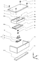
図1は、本発明の実施例1である駆動装置としての超音波モータ1の分解斜視図である。なお、同一部材は同一記号で図示される。101は後述する振動子104が加圧接触する摩擦接触面101aを備える摩擦部材である。102は摩擦部材101の摩擦接触面101aに接触する接触部を備える振動板であり、103は振動板102に対して接着材などにより圧着されている圧電素子である。そして、振動板102に圧電素子103が圧着された状態で圧電素子103に電圧を印加することにより超音波振動を発生させ、振動板102に楕円運動を発生させることができる。なお、振動子104は振動板102と圧電素子103により構成される。105は振動子104を保持するための保持部としての振動子基台である。106は振動子104を、加圧部材107を介してコイルばね108により加圧保持する保持部材である。尚、振動子104を加圧できれば加圧手段はコイルばねに限定されない。コイルばね108はばねの弾性による加圧反力を受けるベース部材109と当接している。ベース部材109は、案内溝109aで転動部材110と当接し、案内溝109aに沿って転動部材110を案内する。ベース部材109に対向するカバー部材111は、カバー部材111に設けられた案内溝111aで転動部材110と当接し、案内溝111aに沿って転動部材110を案内する。カバー部材111は固定部材112にねじ113により固定される。同時に摩擦部材101も固定部材112に固定される。
FIG. 1 is an exploded perspective view of an ultrasonic motor 1 serving as a driving apparatus that is Embodiment 1 of the present invention. In addition, the same member is illustrated with the same symbol.
ベース部材109は、摩擦部材101との相対移動方向において振動子基台105の接触部105aと当接するようにして振動子基台105を収容する。圧電素子103により発生した超音波振動による楕円運動により振動子104は摩擦部材101に対し摩擦部材101の長手方向(X軸方向)に相対移動する。そして、振動子104が接着固定された振動子基台105、及び振動子基台105を収容したベース部材109は摩擦部材101に対し摩擦部材101の長手方向に相対移動する。上記で説明した振動子104と摩擦部材101の相対移動する方向(X軸方向)を相対移動方向と定義する。
The
次に、超音波モータ1の構成部材の詳細について説明する。図2及び図3は図1における振動板102と振動子基台105の接合状態を説明する拡大斜視図である。図2は摩擦部材101側から見た図である。振動板102と振動子基台105は接着材、溶接などにより接合部102bにおいて接合される。図において振動板102の中央部には、相対移動方向に離間して並んだ2個の略球面形状を有する突起部102aが形成されている。本実施例においては略球面形状の突起部を2個としたが、振動子104を相対移動方向に傾かずに保持する為に、離間して並んだ略球面形状を有する突起部の2個以上の複数設けられていればよい。
Next, details of the constituent members of the ultrasonic motor 1 will be described. 2 and 3 are enlarged perspective views for explaining a joined state of the
一方、図3は摩擦部材101側とは逆側から見た図である。図3に示す振動板102の突起部102aが形成されている面の裏面部には圧電素子103が接着材などにより圧着されている。なお、振動板102と圧電素子103の圧着は、圧着されればその方法は限定されない。この圧電素子103は複数の圧電素子膜を積層して一体化したものである。そしてこの圧電素子103に所望の交流電圧を印加することで励振させ、圧電素子103が圧着された振動板102に2つの振動モードを励起する。このとき2つの振動モードの振動位相が所望の位相差となるように設定することで、突起部102aには図2の矢印で示すような楕円運動が発生する。この楕円運動を図2に示すように振動子104で発生させ、摩擦部材101の摩擦接触面101aに伝達することで、摩擦部材101に対して振動子104を相対移動させることが可能となる。なお、前述の圧電素子の積層構造や振動モードに関する詳細は特許文献2に記載された内容と同様である為、それらの説明は割愛する。
On the other hand, FIG. 3 is a view seen from the side opposite to the
図4は振動板102の離間した2つの略球面形状の突起部102a中心部を通る直線を含むXZ面における断面で超音波モータ1を切断した断面図である。保持部材106は圧電素子103と当接し、振動板102の略球面形状の突起部102aは垂直な方向(Z軸方向)にコイルばね108により摩擦部材101へ付勢される。振動子104は、加圧部材107を介して保持部材106によりコイルばね108からの加圧力(付勢力)を受け、摩擦部材101に対し摩擦接触面101aで加圧接触することが可能となっている。そして、前記のとおり突起部102aが楕円運動することにより、振動子104は摩擦部材101に対し図4の左右方向である相対移動方向に相対駆動される。
FIG. 4 is a cross-sectional view of the ultrasonic motor 1 cut along a cross section in the XZ plane including a straight line passing through the central part of two substantially
一方、振動板102に固定された振動子基台105は振動板102に追従して摩擦部材101に対し相対駆動される。振動子基台105はベース部材109と2箇所の接触部105aで当接してベース部材109に収容されており、ベース部材109は振動子基台105に追従して摩擦部材101に対し相対移動する。ここで本実施例では振動子基台105とベース部材109は振動子104の超音波振動を阻害しない為に適度にクリアランスをもった構成としているが、これは、この当接を有して収容する構造に限ったものではない。振動子基台105とおおよそ一対に駆動する為に当接されていればよく、例えば、ばね部材により振動子基台105を相対移動方向へベース部材109に対し付勢を行い、反転駆動時におけるヒステリシスを打ち消す構成等も考えられる。一方、ベース部材109は相対移動方向に振動子基台105から駆動力を与えられると同時にコイルばね108からの加圧力の反力を受ける。
On the other hand, the
加圧部材107は、摩擦部材101の摩擦接触面101aに対しおおよそ垂直な方向のみに移動可能にベース部材109に支持され、加圧部材107は保持部材106を摩擦接触面101aに対し垂直に付勢している。従って、保持部材106は、コイルばね108の付勢方向と平行な方向において振動子を変位可能に保持することができる。保持部材106は加圧部材107との接触部に、摩擦接触面101aに平行であって相対移動方向に直交するY軸まわりに振動子が摩擦接触面101aに対し回転変位可能に保持され得る凸部106aを備える。加圧部材107は平面状の接触部107aで保持部材106の凸部106aと接触することにより凸部106aを中心とした相対移動方向に直交するY軸まわりに回転変位可能とされている。また保持部材106はベース部材109の支持部109bで支持される。支持部109bの形状を相対移動方向において保持部材106に対しクリアランスを持たせることで、保持部材106は凸部106aを中心とした回転変位方向に自在に支持が可能となる。このことにより、例えば摩擦部材101の相対移動方向の傾きに応じて常に振動板102の略球面形状の突起部102aが摩擦接触面101aに垂直に確実に安定して当接することが可能となる。
The
なお、保持部材106の凸部106aは、相対移動方向に直交するY軸に中心軸線が延在する円筒形状で構成されてもよい。即ち、保持部材106の凸部106aは、相対移動方向に直交するY軸まわりに振動子が摩擦接触面101aに対し回転変位可能に保持され得るような構成であれば、曲面形状等いかなる形状を有することも出来る。
In addition, the
図5は相対移動方向と直交するYZ面の断面であって、加圧部材107の鉛直方向(Z軸方向)の中心軸に沿う断面図である。ここで突起部102a部は、振動子104が相対移動方向に平行なX軸まわりに回転変位可能に形成された円弧形状断面の突起部であり、摩擦部材101と点で接触する。
FIG. 5 is a cross-sectional view of the YZ plane orthogonal to the relative movement direction, and is a cross-sectional view taken along the central axis of the
図6は、図5と同様の断面において、それぞれの超音波モータの構成部材に加工公差による形状誤差、例えば接着工程における組み立てによる誤差が発生した場合を示す。かかる場合、上記の本実施例に示されたように、振動板102には略球面形状の突起部102aが設けられている。これにより、突起部102aと摩擦接触面101aとの間に相対的な傾きが発生し、突起部の接触が不安定となることを防ぎ、安定した振動子と摩擦部材の接触状態を得ることができる。
FIG. 6 shows a case where a shape error due to processing tolerance, for example, an error due to assembly in the bonding process occurs in the constituent members of each ultrasonic motor in the same cross section as FIG. In such a case, as shown in the present embodiment, the
図7に示す実施例2は、実施例1の変形型であり、振動板102は実施例1の振動板102の突起部102aの形状を変えた例である。尚、振動板102以外は実施例1と同様な構成である。
The second embodiment shown in FIG. 7 is a modification of the first embodiment, and the
図7は振動板102と摩擦部材101とが圧接されている状態を示した図であり、振動板102の中央部を相対移動方向において切断したXZ断面図である。ここで振動板102は略円筒形状の突起部102cを備え相対移動方向に線状に摩擦部材101の摩擦接触面101aと接触する。
FIG. 7 is a view showing a state in which the
図8も図7の振動板102と摩擦部材101とが圧接されている状態を示した、相対移動方向に垂直なYZ面の断面図である。
8 is also a cross-sectional view of the YZ plane perpendicular to the relative movement direction, showing a state where the
上記のとおり、振動子の突起部102aは、相対移動方向にほぼ平行に延在する中心軸線を有する円筒形状で構成されてもよい。即ち、振動子の突起部102aは、相対移動方向に平行な軸まわりに摩擦接触面に対し回転変位可能に摩擦接触面に接するような構成であれば曲面形状等いかなる形状も有することができる。
As described above, the
振動板が上記した構成を有することにより略円筒形状の突起部102cと摩擦接触面101aとの間に図6と同様な相対的な傾きを発生させることができ、突起部の接触が不安定となることを防ぎ、安定した振動子と摩擦部材の接触状態を得ることができる。
Since the diaphragm has the above-described configuration, a relative inclination similar to that shown in FIG. 6 can be generated between the substantially
以上本発明の好適な実施例について説明したが、本発明はこれらの実施例に限定されず、その要旨の範囲内で種々の変形及び変更が可能である。上記実施例においては摩擦部材が矩形形状からなる摩擦接触面を有する直線駆動型の超音波モータについて述べた。しかしこれには限られず、例えば、摩擦部材が円環形状からなる摩擦接触面を有する回転駆動型の超音波モータであっても良い。 The preferred embodiments of the present invention have been described above, but the present invention is not limited to these embodiments, and various modifications and changes can be made within the scope of the gist thereof. In the above embodiment, the linear drive type ultrasonic motor has been described in which the friction member has a frictional contact surface having a rectangular shape. However, the present invention is not limited to this, and for example, a rotary drive type ultrasonic motor having a frictional contact surface having an annular shape may be used.
1 超音波モータ
101 摩擦部材
101a 摩擦接触面
102 振動板
102a 突起部
102b 接合部
102c 突起部
103 圧電素子
104 振動子
105 振動子基台
105a 接触部
106 保持部材
106a 凸部
107 加圧部材
108 コイルばね
109 ベース部材
109a 案内溝
110 転動部材
111 カバー部材
112 固定部材
113 ねじ
DESCRIPTION OF SYMBOLS 1
Claims (9)
前記振動子と接触する摩擦接触面を有する摩擦部材と、
前記振動子を保持する保持部材と、
前記振動子を前記摩擦部材に加圧する加圧手段と、
を備え、前記圧電素子に印加された電圧により前記振動板が振動することで前記摩擦部材と前記振動子とが相対移動する駆動装置であって、
前記振動子は、前記摩擦接触面に接し、相対移動方向に平行な軸まわりに曲面形状を有する突起部を有し、
前記突起部は、前記摩擦接触面に垂直な方向において、前記加圧手段と重なるように配置されることを特徴とする駆動装置。 A vibrator comprising a piezoelectric element and a diaphragm;
A friction member having a friction contact surface in contact with the vibrator;
A holding member for holding the vibrator;
Pressurizing means for pressurizing the vibrator to the friction member;
Wherein the the voltage applied to the piezoelectric element and the friction member by the vibrating plate is vibrated with the vibrator A driving device for the relative movement,
The vibrator before Symbol frictional contact surface in contact, have a protrusion which have a curved shape about an axis parallel to the relative movement direction,
The driving device according to claim 1, wherein the protrusion is disposed so as to overlap the pressurizing unit in a direction perpendicular to the friction contact surface .
Priority Applications (1)
| Application Number | Priority Date | Filing Date | Title |
|---|---|---|---|
| JP2014182054A JP6415195B2 (en) | 2014-09-08 | 2014-09-08 | Drive device |
Applications Claiming Priority (1)
| Application Number | Priority Date | Filing Date | Title |
|---|---|---|---|
| JP2014182054A JP6415195B2 (en) | 2014-09-08 | 2014-09-08 | Drive device |
Publications (3)
| Publication Number | Publication Date |
|---|---|
| JP2016059121A JP2016059121A (en) | 2016-04-21 |
| JP2016059121A5 JP2016059121A5 (en) | 2017-10-19 |
| JP6415195B2 true JP6415195B2 (en) | 2018-10-31 |
Family
ID=55759094
Family Applications (1)
| Application Number | Title | Priority Date | Filing Date |
|---|---|---|---|
| JP2014182054A Active JP6415195B2 (en) | 2014-09-08 | 2014-09-08 | Drive device |
Country Status (1)
| Country | Link |
|---|---|
| JP (1) | JP6415195B2 (en) |
Families Citing this family (3)
| Publication number | Priority date | Publication date | Assignee | Title |
|---|---|---|---|---|
| JP6808344B2 (en) * | 2016-04-28 | 2021-01-06 | キヤノン株式会社 | Electronic devices equipped with vibration wave motors and vibration wave motors, lens barrels, imaging devices |
| US10763763B2 (en) | 2016-04-28 | 2020-09-01 | Canon Kabushiki Kaisha | Motor and electronic apparatus including motor |
| CN111726034B (en) * | 2020-05-25 | 2021-05-25 | 南京航空航天大学 | Surface-mounted piezoelectric rotating mechanism and driving method thereof |
Family Cites Families (2)
| Publication number | Priority date | Publication date | Assignee | Title |
|---|---|---|---|---|
| JPH08251953A (en) * | 1995-03-13 | 1996-09-27 | Canon Inc | Oscillation driver |
| JP2008079359A (en) * | 2006-09-19 | 2008-04-03 | Nsk Ltd | Actuator for driving slider |
-
2014
- 2014-09-08 JP JP2014182054A patent/JP6415195B2/en active Active
Also Published As
| Publication number | Publication date |
|---|---|
| JP2016059121A (en) | 2016-04-21 |
Similar Documents
| Publication | Publication Date | Title |
|---|---|---|
| KR101685362B1 (en) | Vibration actuator and lens apparatus including the same | |
| JP5773900B2 (en) | motor | |
| JP5975614B2 (en) | Ultrasonic motor and lens apparatus having the same | |
| KR101604991B1 (en) | Ultrasonic motor and lens apparatus including the same | |
| JP2009017735A (en) | Ultrasonic motor | |
| JP6415195B2 (en) | Drive device | |
| JP6257224B2 (en) | Motor and lens device | |
| JP6576214B2 (en) | Vibration type actuator, lens barrel, imaging device and stage device | |
| JP2016059121A5 (en) | ||
| JP6479238B2 (en) | motor | |
| JP5985004B2 (en) | Vibration type motor and lens device having the same | |
| JP2016082611A (en) | Drive unit | |
| JP5985013B2 (en) | Motor and lens barrel | |
| JP2016140130A (en) | Vibration wave motor | |
| JP5985012B2 (en) | Motor and lens barrel | |
| JP2013078230A (en) | Ultrasonic motor and lens device having the same | |
| JP6310514B2 (en) | Vibration type motor and lens device having the same | |
| JP2014209819A (en) | Driving device | |
| JP6106306B2 (en) | Ultrasonic motor and lens apparatus having the same | |
| JP5871763B2 (en) | Ultrasonic motor and lens apparatus having the same | |
| JP2018019518A (en) | Vibration wave motor and optical instrument having vibration wave motor | |
| JP2011259557A (en) | Drive mechanism of mobile by vibration type drive unit | |
| JP2007282373A (en) | Driver, vibration actuator, electronic device, manufacturing method of driver |
Legal Events
| Date | Code | Title | Description |
|---|---|---|---|
| A521 | Written amendment |
Free format text: JAPANESE INTERMEDIATE CODE: A523 Effective date: 20170907 |
|
| A621 | Written request for application examination |
Free format text: JAPANESE INTERMEDIATE CODE: A621 Effective date: 20170907 |
|
| RD05 | Notification of revocation of power of attorney |
Free format text: JAPANESE INTERMEDIATE CODE: A7425 Effective date: 20171214 |
|
| RD04 | Notification of resignation of power of attorney |
Free format text: JAPANESE INTERMEDIATE CODE: A7424 Effective date: 20180126 |
|
| A977 | Report on retrieval |
Free format text: JAPANESE INTERMEDIATE CODE: A971007 Effective date: 20180613 |
|
| A131 | Notification of reasons for refusal |
Free format text: JAPANESE INTERMEDIATE CODE: A131 Effective date: 20180628 |
|
| A521 | Written amendment |
Free format text: JAPANESE INTERMEDIATE CODE: A523 Effective date: 20180823 |
|
| TRDD | Decision of grant or rejection written | ||
| A01 | Written decision to grant a patent or to grant a registration (utility model) |
Free format text: JAPANESE INTERMEDIATE CODE: A01 Effective date: 20180904 |
|
| A61 | First payment of annual fees (during grant procedure) |
Free format text: JAPANESE INTERMEDIATE CODE: A61 Effective date: 20181002 |
|
| R151 | Written notification of patent or utility model registration |
Ref document number: 6415195 Country of ref document: JP Free format text: JAPANESE INTERMEDIATE CODE: R151 |