JP6414847B2 - Developing device and image forming apparatus - Google Patents

Developing device and image forming apparatus Download PDF

Info

Publication number
JP6414847B2
JP6414847B2 JP2014259859A JP2014259859A JP6414847B2 JP 6414847 B2 JP6414847 B2 JP 6414847B2 JP 2014259859 A JP2014259859 A JP 2014259859A JP 2014259859 A JP2014259859 A JP 2014259859A JP 6414847 B2 JP6414847 B2 JP 6414847B2
Authority
JP
Japan
Prior art keywords
developer
toner
conveying means
developing device
sheet member
Prior art date
Legal status (The legal status is an assumption and is not a legal conclusion. Google has not performed a legal analysis and makes no representation as to the accuracy of the status listed.)
Active
Application number
JP2014259859A
Other languages
Japanese (ja)
Other versions
JP2016118747A5 (en
JP2016118747A (en
Inventor
智博 田中
智博 田中
英雄 名倉
英雄 名倉
直樹 田丸
直樹 田丸
昌志 脇坂
昌志 脇坂
中島 良
良 中島
Current Assignee (The listed assignees may be inaccurate. Google has not performed a legal analysis and makes no representation or warranty as to the accuracy of the list.)
Canon Finetech Nisca Inc
Original Assignee
Canon Finetech Nisca Inc
Priority date (The priority date is an assumption and is not a legal conclusion. Google has not performed a legal analysis and makes no representation as to the accuracy of the date listed.)
Filing date
Publication date
Application filed by Canon Finetech Nisca Inc filed Critical Canon Finetech Nisca Inc
Priority to JP2014259859A priority Critical patent/JP6414847B2/en
Priority to US14/976,254 priority patent/US9977369B2/en
Priority to EP15202287.7A priority patent/EP3037891A1/en
Priority to CN201510983066.1A priority patent/CN105739263B/en
Publication of JP2016118747A publication Critical patent/JP2016118747A/en
Publication of JP2016118747A5 publication Critical patent/JP2016118747A5/ja
Application granted granted Critical
Publication of JP6414847B2 publication Critical patent/JP6414847B2/en
Active legal-status Critical Current
Anticipated expiration legal-status Critical

Links

Images

Description

本発明は、電子写真方式等を採用した複写機やプリンタ、あるいはファクシミリ等の画像形成装置に使用される現像装置に関する。 The present invention relates to a developing device used in an image forming apparatus such as a copying machine, a printer, or a facsimile employing an electrophotographic system.

従来、電子写真画像形成装置において、現像剤が使用されて消費された場合に、新たに現像剤を補給する現像剤補給方式が用いられている。現像剤補給方式としては、電子写真画像形成装置に着脱自在なトナーボトルのような現像剤補給容器を交換することにより、現像剤を補給する方式が用いられている。   Conventionally, in an electrophotographic image forming apparatus, when a developer is used and consumed, a developer replenishment method is newly employed in which a new developer is replenished. As the developer replenishing method, a method of replenishing the developer by replacing a developer replenishing container such as a toner bottle that is detachable from the electrophotographic image forming apparatus is used.

例えば、特許文献1には、補給されたトナーを現像装置内に偏って堆積させないように、回転軸のまわりに螺旋状の部材を取り付けた2本の攪拌搬送部材を並べて配置し、現像剤の循環経路を形成する現像装置が記載されている。   For example, in Patent Document 1, two agitating and conveying members, each having a helical member attached around a rotation shaft, are arranged side by side so as to prevent the replenished toner from being deposited in the developing device. A developing device for forming a circulation path is described.

また、特許文献2には、トナー収容部のトナーをトナー供給部へ搬送する攪拌部材の回転攪拌羽根に形成される舌状の撓み方向を常に一定に維持することで、トナーを中央に寄せることのできるトナー供給装置が記載されている。   Further, in Patent Document 2, the toner is brought to the center by always maintaining the tongue-like bending direction formed on the rotating stirring blade of the stirring member that conveys the toner in the toner storage portion to the toner supply portion. A toner supply device is described.

特開平8−30084号公報JP-A-8-30084 特開2010−32754号公報JP 2010-32754 A

しかしながら、特許文献1に記載された現像装置は、2本の螺旋状の回転部材を設けているため、それぞれを回転駆動させるための構造が必要となり、装置の複雑化、大型化、高コスト化を招くといった課題があった。   However, since the developing device described in Patent Document 1 is provided with two spiral rotating members, a structure for rotating and driving each of them is required, which makes the device more complicated, larger, and higher in cost. There was a problem of inviting.

また、特許文献2に記載されたトナー供給装置は、容器内端部に残留するトナーを容器中央部に寄せることでトナーの攪拌を行うもので、攪拌部材の回転軸方向端部側への十分な攪拌ができないため、トナーの帯電不良により濃度ムラの無い画像を得ることができないといった課題があった。   In addition, the toner supply device described in Patent Document 2 stirs the toner by bringing the toner remaining at the inner end of the container toward the center of the container. Therefore, there is a problem that an image having no density unevenness cannot be obtained due to poor charging of the toner.

このような課題を解決するために、本発明者らは、現像剤収容部内の現像剤をより十分に攪拌することで、現像剤担持体により均一に現像剤を供給できる画像形成装置の現像装置を検討している。   In order to solve such a problem, the present inventors have developed a developing device of an image forming apparatus capable of supplying the developer uniformly by a developer carrier by sufficiently stirring the developer in the developer accommodating portion. Are considering.

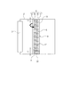
図12は、このような現像装置であって、未だ公知になっていない、試作検討中の現像装置の断面概略図である。   FIG. 12 is a schematic cross-sectional view of such a developing device, which is not yet publicly known, and is under development.

現像装置1は、電子写真方式等を採用した複写機やプリンタ、あるいはファクシミリ等の画像形成装置に使用される装置である。現像剤収容部としての現像容器2は、不図示の像担持体である感光ドラム表面に形成された静電潜像を可視化するための磁石が内包された現像剤担持体としての現像ロール3を有する。また、現像装置1は、現像剤としてのトナー8を帯電させるとともに現像ロール3の表面に形成されたトナー層を規制する現像ブレード4を備えている。さらに、現像剤収容部内の現像剤を攪拌搬送する部材として、現像容器2には、現像ロール3側へトナー8を攪拌しつつ供給・搬送する攪拌搬送部材6を備えている。   The developing device 1 is an apparatus used for an image forming apparatus such as a copying machine, a printer, or a facsimile employing an electrophotographic system. A developer container 2 as a developer container includes a developing roll 3 as a developer carrier that contains a magnet for visualizing an electrostatic latent image formed on the surface of a photosensitive drum, which is an image carrier (not shown). Have. The developing device 1 also includes a developing blade 4 that charges the toner 8 as a developer and regulates the toner layer formed on the surface of the developing roll 3. Further, as a member for stirring and transporting the developer in the developer accommodating portion, the developing container 2 is provided with a stirring and transporting member 6 that supplies and transports the toner 8 to the developing roll 3 side while stirring.

トナーボトル7は、現像容器2に対して着脱可能な現像剤補給部であり、その現像剤補給部内には磁性一成分トナー8が収容され、現像容器2へのトナー8の補給が行われる開口であるトナー補給口9を有する。また、トナーボトル7は、その内部で回転可能な攪拌部材10を有する。攪拌部材10は、トナーボトル7のトナー8を、トナー補給口9を介して現像容器2へ供給する。供給されたトナー8は、攪拌搬送部材6におけるトナー補給口9に対向する対向領域11へ案内される。   The toner bottle 7 is a developer replenishing portion that can be attached to and detached from the developing container 2. The developer replenishing portion contains a magnetic one-component toner 8, and an opening through which the toner 8 is replenished to the developing container 2. A toner replenishing port 9. Further, the toner bottle 7 has a stirring member 10 that can rotate inside thereof. The stirring member 10 supplies the toner 8 in the toner bottle 7 to the developing container 2 through the toner supply port 9. The supplied toner 8 is guided to a facing area 11 facing the toner supply port 9 in the stirring and conveying member 6.

図13は、攪拌搬送部材6が有する複数の現像剤搬送手段を説明する模式図であり、現像容器2にトナーボトル7をトナー補給口9と攪拌搬送部材6の対向領域11とが対向可能となるように取り付けた構成の内部を、その上部から見た模式図である。   FIG. 13 is a schematic diagram for explaining a plurality of developer conveying means included in the agitating / conveying member 6. The toner bottle 7 can be opposed to the developing container 2 with the toner supply port 9 and the opposed region 11 of the agitating / conveying member 6. It is the schematic diagram which looked at the inside of the structure attached so that it might become from the upper part.

攪拌搬送部材6は、現像ロール3の回転軸方向と同じ方向に沿って延在する回転軸12と、その回転軸12に対して直交する方向の辺と回転軸12の軸方向の辺とを有する搬送面13を備えたシート部材14とを有している。シート部材14は、回転軸12に取り付けられて、現像剤収容部である現像容器2の内部を、回転軸12を中心に回転可能に設けられている。また、シート部材14は、回転半径方向における回転中心から回転端までの間に、回転軸12の軸方向に現像剤であるトナー8を搬送する現像剤搬送手段を複数有している。   The agitating / conveying member 6 includes a rotation shaft 12 extending along the same direction as the rotation axis direction of the developing roller 3, a side perpendicular to the rotation shaft 12, and a side in the axial direction of the rotation shaft 12. And a sheet member 14 having a conveying surface 13. The sheet member 14 is attached to the rotary shaft 12 and is provided so as to be rotatable around the rotary shaft 12 inside the developing container 2 which is a developer accommodating portion. Further, the sheet member 14 includes a plurality of developer conveying means for conveying the toner 8 as the developer in the axial direction of the rotary shaft 12 between the rotation center and the rotation end in the rotation radius direction.

現像容器2には、攪拌搬送部材6の回転軸12より下方に、トナー補給口9から供給されたトナー8が貯留されている。また、シート部材14の搬送面13には、回転軸12の回りをトナー補給口9から現像容器2の内部下方を経て現像ロール3の方向へ回転移動することで、回転軸12の軸方向に沿ってトナーを搬送移動させる複数の現像剤搬送手段を備えている。ここでは、現像剤搬送手段は、搬送面13に回転軸12の軸方向に沿って延在する、第一の現像剤搬送手段15と第二の現像剤搬送手段16とから構成されている。そして、第一の現像剤搬送手段15は、第二の現像剤搬送手段16よりも回転軸12の回転半径方向における回転端の側に併設して配置されている。   In the developing container 2, toner 8 supplied from the toner replenishing port 9 is stored below the rotating shaft 12 of the stirring and conveying member 6. Further, on the conveying surface 13 of the sheet member 14, the sheet rotates around the rotation shaft 12 from the toner replenishing port 9 toward the developing roll 3 through the inside of the developing container 2, thereby moving in the axial direction of the rotation shaft 12. A plurality of developer conveying means for conveying and moving the toner is provided. Here, the developer conveying means includes a first developer conveying means 15 and a second developer conveying means 16 that extend on the conveying surface 13 along the axial direction of the rotary shaft 12. The first developer conveying means 15 is arranged adjacent to the rotating end in the rotational radius direction of the rotating shaft 12 relative to the second developer conveying means 16.

ここで、第一の現像剤搬送手段15によるトナー8の搬送方向と第二の現像剤搬送手段16によるトナー8の搬送方向とは回転軸12の軸方向に関して互いに逆方向となるように構成されている。このような搬送方向が互いに逆方向である現像剤搬送手段15、16は、攪拌搬送部材6の回転に伴って、搬送面13の面にそれぞれのトナー搬送経路を形成する。搬送面13の面に沿って第一の現像剤搬送手段15で回転軸12の軸方向の一方端側へ搬送されたトナー8は、そこで第二の現像剤搬送手段16によって、反対側の端部側へ向かって循環するように搬送される。これにより、現像容器2の端部でのトナー8の滞留を防止して、より均一化されるようにトナー8を攪拌することができる。   Here, the conveying direction of the toner 8 by the first developer conveying means 15 and the conveying direction of the toner 8 by the second developer conveying means 16 are configured to be opposite to each other with respect to the axial direction of the rotary shaft 12. ing. The developer conveying means 15 and 16 whose conveying directions are opposite to each other form respective toner conveying paths on the surface of the conveying surface 13 as the stirring and conveying member 6 rotates. The toner 8 conveyed to the one end side in the axial direction of the rotary shaft 12 by the first developer conveying means 15 along the surface of the conveying surface 13 there is an end on the opposite side by the second developer conveying means 16 there. It is conveyed so as to circulate toward the part side. Thereby, the toner 8 can be prevented from staying at the end of the developing container 2 and the toner 8 can be stirred so as to be more uniform.

第一の現像剤搬送手段15と第二の現像剤搬送手段16とは、シート部材14の現像剤搬送面13に、以下に述べるような所定形状の開口部17がそれぞれ列状に複数配置されている。   The first developer conveying means 15 and the second developer conveying means 16 each have a plurality of predetermined openings 17 arranged in a row on the developer conveying surface 13 of the sheet member 14 as described below. ing.

開口部17は、軸方向に沿ったトナー搬送方向に直交する向きの開口の大きさ(開口幅)が、トナー搬送方向に向かって大きくなるような形状を有している。搬送面13が回転軸12の軸回りを回動すると、搬送面13に押し動かされるトナー8が搬送面13の表側から裏側(回転方向の前方から後方)へ向けて開口部17を抜ける際に、開口部17の開口幅の小さい方から大きい方へ移動する(例えば、図14の矢印の方向)。このトナー8の移動によって、所定の方向へのトナー搬送が生じる。これは、回転する搬送面13に対するトナー8からの圧力が小さくなる方向へ、すなわち、開口幅が大きくなる方向(例えば、図14の矢印方向)へ、トナー8が搬送面13に押されて移動することで上述のような所定方向へのトナー搬送が行われることによる。   The opening 17 has such a shape that the size of the opening (opening width) in the direction perpendicular to the toner conveyance direction along the axial direction increases toward the toner conveyance direction. When the transport surface 13 rotates about the axis of the rotation shaft 12, the toner 8 pushed and moved by the transport surface 13 passes through the opening 17 from the front side to the back side (front to back in the rotation direction) of the transport surface 13. Then, the opening 17 moves from the smaller opening width to the larger one (for example, in the direction of the arrow in FIG. 14). This movement of the toner 8 causes toner conveyance in a predetermined direction. This is because the toner 8 is pushed and moved by the conveyance surface 13 in the direction in which the pressure from the toner 8 on the rotating conveyance surface 13 decreases, that is, in the direction in which the opening width increases (for example, the arrow direction in FIG. 14). This is because the toner is conveyed in the predetermined direction as described above.

図14は、現像剤搬送手段としてのシート部材14の搬送面13に形成された開口部17の一例を示す模式図である。   FIG. 14 is a schematic diagram illustrating an example of the opening 17 formed on the conveyance surface 13 of the sheet member 14 as the developer conveyance unit.

開口部17は、搬送面13が受けるトナー8の圧力が小さくなるように開口幅が大きくなるような、トナー8を搬送する方向とは逆方向に三角形の頂点が向いている形状である。したがって、第一の現像剤搬送手段15の複数の開口部17の三角形の頂点の向きと、第二の現像剤搬送手段16の複数の開口部17の三角形の頂点の向きとは、互いに逆の関係になっている。   The opening 17 has a shape in which the apex of the triangle faces in the direction opposite to the direction in which the toner 8 is conveyed so that the opening width increases so that the pressure of the toner 8 received by the conveying surface 13 decreases. Accordingly, the direction of the apexes of the triangles of the plurality of openings 17 of the first developer conveying means 15 and the direction of the apexes of the triangles of the plurality of openings 17 of the second developer conveying means 16 are opposite to each other. It has become a relationship.

上述したような構成の攪拌搬送部材6を回転させることにより、その回転軸12の方向に沿ってトナー8を搬送面13の面上で循環させることができる。   By rotating the stirring and conveying member 6 having the above-described configuration, the toner 8 can be circulated on the surface of the conveying surface 13 along the direction of the rotation shaft 12.

しかしながら、現像容器2にあるトナー8は、攪拌搬送部材6が回転することにより、その搬送面13に形成された2つの現像剤搬送手段15、16によって、それぞれ現像容器2の両端部へ搬送される。ここで、第一の現像剤搬送手段15によって現像容器2の一方端へ搬送されるトナー8と、第二の現像剤搬送手段16によって現像容器2の他方側の端部へ搬送されるトナー8と、が存在するため、現像容器2の端部では、トナー8が攪拌されるたびにトナー8のトナー面高さ(剤面高さ)が上下に大きく変動している。そのため、現像容器2の内部のトナー8の残量を検知しようとすると、トナー面の上下変動により、残量検知精度が不安定になるという新たな課題を、本発明者らは見出した。   However, the toner 8 in the developing container 2 is transported to both ends of the developing container 2 by the two developer transporting means 15 and 16 formed on the transporting surface 13 as the stirring and transporting member 6 rotates. The Here, the toner 8 conveyed to one end of the developing container 2 by the first developer conveying means 15 and the toner 8 conveyed to the other end of the developing container 2 by the second developer conveying means 16. Therefore, at the end of the developing container 2, the toner surface height (agent surface height) of the toner 8 greatly fluctuates up and down each time the toner 8 is agitated. For this reason, the present inventors have found a new problem that when the remaining amount of the toner 8 inside the developing container 2 is detected, the remaining amount detection accuracy becomes unstable due to the vertical fluctuation of the toner surface.

本発明は、現像剤を収容する現像剤収容部と、前記現像剤収容部に収容されている現像剤の内で、現像剤検知可能領域に在る現像剤を検知する現像剤検知ユニットと、前記現像剤収容部で回転軸に対して回転自在に配置されるシート部材と、備え、前記シート部材は、前記回転軸の軸方向一端部側に向かう方向に現像剤を搬送する第一の現像剤搬送手段と、前記第一の現像剤搬送手段とは、前記回転軸との距離が異なる位置に形成され、前記回転軸の軸方向他端部側に向かう方向に現像剤を搬送する第二の現像剤搬送手段と、を有し、前記現像剤検知ユニットは、前記現像剤収容部における前記一端部に対応する位置に配置され、前記現像剤検知可能領域における、前記シート部材の前記一端部側に向かう現像剤搬送能力は、前記第一の現像剤搬送手段の現像剤搬送方向において、前記現像剤検知可能領域よりも上流側の領域における、前記第一の現像剤搬送手段の前記一端部側に向かう現像剤搬送能力よりも小さいことを特徴とする。 The present invention includes a developer accommodating portion for accommodating the developer, among the developer contained in the developer containing portion, a developer detection unit for detecting the developer located in the developer detectable regions, A sheet member arranged to be rotatable with respect to the rotation axis in the developer accommodating portion, and the sheet member conveys the developer in a direction toward one end side in the axial direction of the rotation shaft. The agent transporting unit and the first developer transporting unit are formed at positions where the distance from the rotation shaft is different, and the second transports the developer in a direction toward the other axial end of the rotation shaft. The developer conveying means, and the developer detecting unit is disposed at a position corresponding to the one end of the developer containing portion, and the one end of the sheet member in the developer detectable region The developer transport capability toward the side is the first development In the developer conveying direction of the conveying means, wherein the upstream region from the developer detectable regions, and wherein the less than the developer conveying capacity towards the one end side of the first developer conveying means .

本発明によれば、現像剤収容部内の現像剤を十分に攪拌することができるとともに、現像剤収容部内の現像剤を精度良く検知できる現像装置を提供することができる。 According to the present invention, it is possible to sufficiently agitated developer in the developer accommodating portion, it is possible to provide a developing apparatus and developer in the developer container can be accurately detected.

本発明に係る現像装置の概略図である。1 is a schematic view of a developing device according to the present invention. 本発明に係る現像装置の内部を上部から見た模式図である。It is the schematic diagram which looked at the inside of the developing device concerning the present invention from the upper part. 透磁率センサ22の周辺の構成を現像容器2の側面から見た断面模式図である。3 is a schematic cross-sectional view of the configuration around the magnetic permeability sensor 22 as viewed from the side surface of the developing container 2. FIG. 現像容器内のトナー残量に対する透磁率センサの検知出力を表した図である。FIG. 6 is a diagram illustrating a detection output of a magnetic permeability sensor with respect to a toner remaining amount in a developing container. 比較例の現像容器の内部を上部から見た模式図である。It is the schematic diagram which looked at the inside of the development container of a comparative example from the upper part. 比較例の透磁率センサ周辺の構成を現像容器の側面から見た断面模式図である。It is the cross-sectional schematic diagram which looked at the structure of the magnetic permeability sensor periphery of the comparative example from the side surface of the developing container. 比較例の現像容器内のトナー残量に対する透磁率センサの検知出力を表した図である。It is a figure showing the detection output of the magnetic permeability sensor with respect to the toner remaining amount in the developing container of the comparative example. 本発明に係る第2実施形態の現像装置の内部を上部から見た模式図である。It is the schematic diagram which looked at the inside of the developing device of a 2nd embodiment concerning the present invention from the upper part. 本発明に係る第3実施形態の現像装置の内部を上部から見た模式図である。It is the schematic diagram which looked at the inside of the developing device of a 3rd embodiment concerning the present invention from the upper part. 本発明に係る第4実施形態の現像装置の内部を上部から見た模式図である。It is the schematic diagram which looked at the inside of the developing device of a 4th embodiment concerning the present invention from the upper part. 本発明に係る第5実施形態の現像装置の内部を上部から見た模式図である。It is the schematic diagram which looked at the inside of the developing device of a 5th embodiment concerning the present invention from the upper part. 本発明に関連した試作検討中の現像装置の断面概略図である。FIG. 2 is a schematic cross-sectional view of a developing device under examination related to the present invention. 攪拌搬送部材が有する複数の現像剤搬送手段を説明する模式図である。FIG. 6 is a schematic diagram illustrating a plurality of developer conveying units included in the agitating / conveying member. シート部材の搬送面に形成された開口部の模式図である。It is a schematic diagram of the opening part formed in the conveyance surface of a sheet member.

〔第1実施形態〕
(現像装置の構成)
図1は本発明に係る現像装置1の概略図であり、図2は現像剤収容部としての現像容器2にトナーボトル7をトナー補給口9と攪拌搬送部材6の対向領域11とが対向可能となるように取り付けた構成の内部を、その上部から見た模式図である。
[First Embodiment]
(Configuration of developing device)
FIG. 1 is a schematic view of a developing device 1 according to the present invention, and FIG. 2 shows that a toner bottle 7 can be opposed to a toner replenishing port 9 and a facing region 11 of an agitating and conveying member 6 in a developing container 2 as a developer container. It is the schematic diagram which looked at the inside of the structure attached so that it might become.

本実施形態の現像装置1は、公知前の試作検討中の図12乃至図14の構成を有する現像装置1に、後述する2つの現像剤搬送手段である第一の現像剤搬送手段15及び第二の現像剤搬送手段16に、現像剤検知可能領域A(検知領域)及び現像剤検知部材(現像剤検知ユニット)22の構成を付加するものである。その2つの現像剤搬送手段は、シート状の部材であるシート部材14に、回転半径方向における回
転中心から半径方向外側の自由端までの間に配され、回転軸12の軸方向に沿って現像剤8を搬送する第一の現像剤搬送手段15と、第一の現像剤搬送手段とは逆方向に軸方向に沿って現像剤8を搬送する第二の現像剤搬送手段16と、を配する構成を有している。
The developing device 1 according to the present embodiment is different from the developing device 1 having the configuration shown in FIGS. 12 to 14 that is under examination of a prototype before publicly known, in the first developer conveying means 15 and the second developer conveying means described later. The configuration of a developer detectable area A (detection area) and a developer detection member (developer detection unit) 22 is added to the second developer conveying means 16. The two developer conveying means are arranged on the sheet member 14, which is a sheet-like member, between the rotational center in the rotational radius direction and the free end on the radially outer side, and along the axial direction of the rotational shaft 12. A first developer conveying means 15 for conveying the developer 8, and a second developer conveying means 16 for conveying the developer 8 along the axial direction in the direction opposite to the first developer conveying means. It has a configuration to distribute.

本実施形態に係る現像装置1は、感光ドラム等の像担持体の表面に形成された静電潜像を、現像容器2に収容された現像剤8を、現像ロール3を介して像担持体表面へ供給し現像して画像形成する画像形成装置に用いるものである。   In the developing device 1 according to the present embodiment, an electrostatic latent image formed on the surface of an image carrier such as a photosensitive drum, a developer 8 accommodated in a developer container 2 is passed through a developing roll 3 and the image carrier. It is used in an image forming apparatus that supplies an image to the surface and develops it to form an image.

このような本実施形態では、2つの搬送方向が互いに逆方向である現像剤搬送手段15、16により、攪拌搬送部材6の回転に伴ってシート部材14の搬送面13にトナー搬送経路5を形成する。このトナー搬送経路5は、トナーボトル7のトナー補給口9から補給されたトナー8が、搬送面13に沿って第一の現像剤搬送手段15によって回転軸12の一方端側へ搬送され、そこで第二の現像剤搬送手段16によって回転軸12の反対方向端側へ向かって搬送面13に沿って循環するように搬送されることで形成される。このように攪拌搬送部材6により、現像剤を搬送する現像剤搬送装置が構成されている。 In this embodiment, the toner conveying path 5 is formed on the conveying surface 13 of the sheet member 14 by the rotation of the agitating and conveying member 6 by the developer conveying means 15 and 16 whose two conveying directions are opposite to each other. To do. In the toner transport path 5, the toner 8 replenished from the toner replenishing port 9 of the toner bottle 7 is transported along the transport surface 13 to the one end side of the rotating shaft 12 by the first developer transport means 15. It is formed by being conveyed by the second developer conveying means 16 so as to circulate along the conveying surface 13 toward the opposite end of the rotating shaft 12. In this way, the agitation transport member 6 constitutes a developer transport device that transports the developer.

これにより、現像剤搬送方向を回転軸として回転する攪拌搬送部材6により、現像容器2に補給されたトナー8は、攪拌搬送部材6の回転軸12の両端部での滞留を抑えつつ、よりトナー8の攪拌状態を回転軸12の方向に関しても均一して、現像ロール3へ搬送される。 As a result, the toner 8 replenished to the developing container 2 by the stirring / conveying member 6 that rotates about the developer conveying direction as the rotation axis can be more toner while suppressing staying at both ends of the rotating shaft 12 of the stirring / conveying member 6. 8 is made uniform in the direction of the rotary shaft 12 and is conveyed to the developing roll 3.

本実施形態では、回転軸12を中心に回転可能なシート部材14はPPS樹脂を使用して形成されている。シート部材14の搬送面13に形成された開口部17は、底辺の長さが11mm、高さが16mmの二等辺三角形の形状の孔を有するものである。そして、開口部17は、軸方向に沿ったトナー搬送方向に直交する向きの開口の大きさ(開口幅)が、トナー搬送方向に向かって拡がって大きくなるような形状を有している。つまり、この開口の形状により、開口幅の小さい方から大きい方へ向かってトナー流が形成される。 In this embodiment, the sheet | seat member 14 which can rotate centering on the rotating shaft 12 is formed using PPS resin. The opening 17 formed in the conveying surface 13 of the sheet member 14 has an isosceles triangular hole having a base length of 11 mm and a height of 16 mm. The opening 17 has such a shape that the size of the opening (opening width) in the direction perpendicular to the toner conveyance direction along the axial direction expands and becomes larger in the toner conveyance direction. In other words, a toner flow is formed from the smaller opening width toward the larger opening width due to the shape of the opening.

なお、シート部材14の材料や開口部17の形状や大きさは、この例に限られるものではない。   Note that the material of the sheet member 14 and the shape and size of the opening 17 are not limited to this example.

(現像剤搬送手段と現像剤検知可能領域の構成)
現像剤搬送手段は、シート部材14の搬送面13に回転軸12の軸方向に延在する、第一の現像剤搬送手段15及び第一の現像剤搬送手段15とは回転軸12との距離が異なる位置で撹拌部材6に設けられている第二の現像剤搬送手段16とから構成されている。そして、第一の現像剤搬送手段15及び第二の現像剤搬送手段16は、それぞれ複数の開口部17が搬送面13に回転軸12に沿った方向に列状に並んで形成されている。
(Configuration of developer conveying means and developer detectable area)
The developer conveying means extends in the axial direction of the rotating shaft 12 on the conveying surface 13 of the sheet member 14. The first developer conveying means 15 and the first developer conveying means 15 are spaced from the rotating shaft 12. Are composed of the second developer conveying means 16 provided on the stirring member 6 at different positions . The first developer conveying means 15 and the second developer conveying means 16 are each formed with a plurality of openings 17 arranged in a line in the direction along the rotation axis 12 on the conveying surface 13.

それらの列状に並んだ開口部17のうち、現像剤検知部材22側端の最も端部側に位置する開口部17と、現像剤検知部材22が配された現像容器2の内壁と、の間の現像剤検知可能領域Aが入る間隔をL1とし、反対側の列端の最も端部側に位置する開口部17と、その側の現像容器2の内壁と、の間の間隔をL2とすると、L1>L2の関係を有している。この関係は、第一の現像剤搬送手段15の開口部17の配列と第二の現像剤搬送手段16の開口部17の配列との双方がこの関係を有している。そして、L1とL2の距離差は、開口部17が回転軸12の軸方向に1つ入るものである。 Of the openings 17 arranged in a row, the opening 17 located closest to the end of the developer detection member 22 and the inner wall of the developer container 2 in which the developer detection member 22 is disposed The interval between the developer detectable areas A is L1, and the interval between the opening 17 located on the most end side of the opposite row end and the inner wall of the developer container 2 on that side is L2. Then, there is a relationship of L1> L2. In this relationship, both the arrangement of the openings 17 of the first developer conveying means 15 and the arrangement of the openings 17 of the second developer conveying means 16 have this relationship. The distance difference between L1 and L2 is such that one opening 17 is inserted in the axial direction of the rotary shaft 12.

ここで、検知領域である現像剤検知可能領域Aとは、現像剤検知部材22がトナー8の有無を判断できる領域である。 Here, the developer detectable area A, which is a detection area, is an area where the developer detection member 22 can determine the presence or absence of the toner 8.

本実施形態における現像剤検知部材22の検知領域は、現像剤検知部材22のトナー検知面から5mm以内となっている。この現像剤検知部材22のトナー検知領域が大きくなれば、現像剤検知可能領域Aも対応して大きくなる。   In the present embodiment, the detection area of the developer detection member 22 is within 5 mm from the toner detection surface of the developer detection member 22. When the toner detection area of the developer detection member 22 is increased, the developer detectable area A is correspondingly increased.

(現像剤検知部材の構成)
現像剤検知部材22は、図1に示すように、攪拌搬送部材6のシート部材14が回転軸12の周囲を回転する際に、シート部材14の回転半径方向に沿った辺が対面する位置の現像容器2の内面に配されている。
(Configuration of developer detection member)
As shown in FIG. 1, the developer detecting member 22 is located at a position where the sides along the rotational radius direction of the sheet member 14 face each other when the sheet member 14 of the stirring and conveying member 6 rotates around the rotation shaft 12. Arranged on the inner surface of the developing container 2.

さらに、本実施形態では、現像容器2の上部から見た図2に示すように、シート部材14の搬送面13に列状に配された開口部17から形成される2つの現像剤搬送手段15、16を、現像剤検知可能領域Aに対応するシート部材14の部位に開口部17を設けないようにしている。このようにして、2つの現像剤搬送手段15、16は、現像剤検知可能領域Aには設けられていない。そして、この現像剤検知可能領域Aに対面する現像容器2の内面に、現像剤検知部材22が配されている。   Furthermore, in this embodiment, as shown in FIG. 2 as viewed from the top of the developing container 2, the two developer conveying means 15 formed from the openings 17 arranged in a line on the conveying surface 13 of the sheet member 14. 16, the opening 17 is not provided in the portion of the sheet member 14 corresponding to the developer detectable region A. In this way, the two developer conveying means 15 and 16 are not provided in the developer detectable region A. A developer detection member 22 is disposed on the inner surface of the developer container 2 facing the developer detectable region A.

現像剤検知部材22は、透磁率センサを用いた残量検知システムである。透磁率センサ22は、現像剤検知可能領域A内のトナー8中に含まれる磁性体の透磁率に応じたセンサ出力電圧を出力し、このセンサ出力電圧値が基準電圧値を超えたかどうかの検知を行う。   The developer detection member 22 is a remaining amount detection system using a magnetic permeability sensor. The magnetic permeability sensor 22 outputs a sensor output voltage corresponding to the magnetic permeability of the magnetic material contained in the toner 8 in the developer detectable area A, and detects whether or not the sensor output voltage value exceeds the reference voltage value. I do.

透磁率センサ22は、攪拌搬送部材6の1回転を1サイクルとし、その1サイクルの間に一定の周期でサンプリングを行う。1サイクルのサンプリング結果に基づいて、検知されたセンサ出力電圧値が基準電圧値を超えた回数を計数係数し、透磁率センサ22のサンプリング1サイクル当たりの基準電圧値超えの回数が予め定めた閾値未満の場合はトナー無とし、閾値以上の場合はトナー有と判断する構成となっている。   The magnetic permeability sensor 22 performs one rotation of the agitating and conveying member 6 as one cycle, and performs sampling at a constant cycle during the one cycle. The number of times the detected sensor output voltage value exceeds the reference voltage value is counted based on the sampling result of one cycle, and the number of times the permeability sensor 22 exceeds the reference voltage value per sampling cycle is a predetermined threshold value. When the value is less than the threshold value, no toner is used.

図3は、透磁率センサ22の周辺の構成を現像容器2の側面から見た断面模式図であり、現像容器2の内部を、回転軸12を中心にしてシート部材14が回転することで、攪拌されるトナー8の剤面(トナー面)の変化の様子を模式的に表したものである。   FIG. 3 is a schematic cross-sectional view of the configuration around the magnetic permeability sensor 22 as viewed from the side surface of the developing container 2. The sheet member 14 rotates around the rotation shaft 12 inside the developing container 2. 3 schematically shows how the surface of the toner 8 to be stirred (toner surface) changes.

本実施形態では、現像剤検知可能領域Aを通過するシート部材14の搬送面13に開口部17を設けないことで、現像剤検知可能領域に第一の現像剤搬送手段15及び第二の現像剤搬送手段16を設けないという構成を実現している。   In this embodiment, the opening 17 is not provided in the conveyance surface 13 of the sheet member 14 that passes through the developer detectable area A, so that the first developer conveying means 15 and the second development are provided in the developer detectable area. The structure which does not provide the agent conveyance means 16 is implement | achieved.

この現像剤検知可能領域A内に透磁率センサ22へ向かう現像剤搬送機能を抑制する構成により、現像剤検知可能領域A内での攪拌搬送部材6による回転軸12に沿った方向のトナー8の移動を抑制している。これにより、現像剤検知可能領域Aにおける、シート部材14の一端部側に向かう現像剤搬送能力は、第一の現像剤搬送手段15の現像剤搬送方向において、現像剤検知可能領域Aの上流側の領域における、第一の現像剤搬送手段15の一端部側に向かう現像剤搬送能力よりも小さいため、検知領域における透磁率センサ22に向かうトナー搬送機能を抑制することができる。 With the configuration in which the developer conveying function toward the magnetic permeability sensor 22 is suppressed in the developer detectable area A, the toner 8 in the direction along the rotation axis 12 by the agitating and conveying member 6 in the developer detectable area A. The movement is suppressed. As a result, the developer transport capability toward the one end side of the sheet member 14 in the developer detectable region A is upstream of the developer detectable region A in the developer transport direction of the first developer transport unit 15. In this area, the toner conveying function toward the magnetic permeability sensor 22 in the detection area can be suppressed because it is smaller than the developer conveying ability toward the one end of the first developer conveying means 15 .

このように、回転軸12の軸方向へのトナー8の移動を抑えることにより、シート部材14がトナー貯まりの外にあっても(図3(a))、また、シート部材14がトナー貯まりの中を回転移動中であっても(図3(b))、現像剤検知可能領域A内のトナー8のトナー面高さの上下変動は低減される。そのため、透磁率センサ22のトナー有無検知の精度をより安定させることができる。   In this way, by suppressing the movement of the toner 8 in the axial direction of the rotating shaft 12, even if the sheet member 14 is outside the toner reservoir (FIG. 3A), the sheet member 14 is not stored in the toner reservoir. Even when the inside is rotating (FIG. 3B), the vertical fluctuation of the toner surface height of the toner 8 in the developer detectable region A is reduced. Therefore, the accuracy of the presence / absence detection of the toner of the magnetic permeability sensor 22 can be further stabilized.

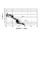
次に、現像容器2内のトナー8を消費しながら、透磁率センサ22による残量検知の出力をモニタリングし、2回の測定を行った。   Next, while the toner 8 in the developing container 2 was consumed, the output of the remaining amount detection by the magnetic permeability sensor 22 was monitored, and the measurement was performed twice.

図4は、その測定結果であり、現像容器2内のトナー残量に対する透磁率センサ22の検知出力を、縦軸を残量検知の出力値、横軸を現像容器2内のトナー残量とする図である。   FIG. 4 shows the measurement results. The detected output of the magnetic permeability sensor 22 with respect to the remaining amount of toner in the developing container 2 is represented by the output value of the remaining amount detection on the vertical axis and the remaining toner amount in the developing container 2 on the horizontal axis. It is a figure to do.

透磁率センサ22の検知出力は、現像剤検知可能領域A内のトナー面高さが安定していることにより、1回目の測定(N=1)と2回目の測定(N=2)との両方で、ともに残量検知出力値のリップルが小さくなり、現像容器2内のトナー残量を精度よく検知することができる。   The detection output of the magnetic permeability sensor 22 indicates that the first measurement (N = 1) and the second measurement (N = 2) because the toner surface height in the developer detectable region A is stable. In both cases, the ripple of the remaining amount detection output value is reduced, and the remaining amount of toner in the developing container 2 can be detected with high accuracy.

(比較例)
図5は、比較例として、公知前の試作検討中の現像装置1に透磁率センサ22を本実施形態と同じ位置に設けた現像容器2の内部を上部から見た模式図である。
(Comparative example)
As a comparative example, FIG. 5 is a schematic view of the inside of the developing container 2 in which the magnetic permeability sensor 22 is provided at the same position as that of the present embodiment in the developing device 1 under the trial examination before publicly known, as viewed from above.

図5にあるように、現像剤検知可能領域Aに含まれるシート部材14の搬送面13に、2つの現像剤搬送手段15、16の端部にそれぞれ開口部17が設けられており、この現像剤検知可能領域A内にも2つの現像剤搬送手段15,16が存在していることが分かる。   As shown in FIG. 5, an opening 17 is provided at each end of the two developer conveying means 15 and 16 on the conveying surface 13 of the sheet member 14 included in the developer detectable area A. It can be seen that there are also two developer conveying means 15 and 16 in the agent detectable region A.

図6は、比較例の透磁率センサ22周辺の構成を現像容器2の側面から見た断面模式図である。これは、現像容器2の内部を、回転軸12を中心にしてシート部材14が回転することで、攪拌されるトナー8の剤面の変化の様子を模式的に表したものである。   FIG. 6 is a schematic cross-sectional view of the configuration around the magnetic permeability sensor 22 of the comparative example as seen from the side surface of the developing container 2. This schematically shows how the surface of the toner 8 to be agitated changes as the sheet member 14 rotates around the rotation shaft 12 inside the developing container 2.

この比較例では、現像容器2内のトナー8は、攪拌搬送部材6が回転することにより、シート部材14の搬送面13に設けられた第一の現像剤搬送手段15によって現像容器2の端部(回転軸12の軸方向端部)に搬送されるトナー8と、第二の現像剤搬送手段16によって現像容器2の端部とは反対側の端部へ搬送されるトナー8と、が存在する。   In this comparative example, the toner 8 in the developing container 2 is fed to the end portion of the developing container 2 by the first developer conveying means 15 provided on the conveying surface 13 of the sheet member 14 by the rotation of the agitating and conveying member 6. There is toner 8 conveyed to the axial end of the rotating shaft 12 and toner 8 conveyed to the end opposite to the end of the developer container 2 by the second developer conveying means 16. To do.

このように、現像容器2の端部では、攪拌搬送部材6によって攪拌される度に、トナー8が現像容器2の攪拌搬送部材6の軸方向端部に押し寄せるとともに、現像容器2の端部にあるトナー8を現像容器2の内側に向かって搬送する。そのため、シート部材14がトナー貯まりの外にあるとき(図6(a))と、シート部材14がトナー貯まりの中を回転移動中のとき(図6(b))とでは、トナー面高さが上下に大きく変動してしまい、トナー面高さは安定しない。   As described above, at the end of the developing container 2, the toner 8 presses against the end in the axial direction of the agitating / conveying member 6 of the developing container 2 every time it is agitated by the agitating / conveying member 6. A certain toner 8 is conveyed toward the inside of the developing container 2. Therefore, when the sheet member 14 is outside the toner reservoir (FIG. 6A) and when the sheet member 14 is rotating in the toner reservoir (FIG. 6B), the toner surface height is increased. Greatly fluctuates up and down, and the toner surface height is not stable.

次に、比較例の現像容器2内のトナー8を消費しながら、透磁率センサ22による残量検知の出力をモニタリングし、2回の測定を行った。   Next, the output of the remaining amount detection by the magnetic permeability sensor 22 was monitored while consuming the toner 8 in the developing container 2 of the comparative example, and the measurement was performed twice.

図7は、その測定結果であり、現像容器2内のトナー残量に対する透磁率センサ22の検知出力を、縦軸を残量検知の出力値、横軸を現像容器2内のトナー残量とする図である。   FIG. 7 shows the measurement result. The detection output of the magnetic permeability sensor 22 with respect to the remaining amount of toner in the developing container 2 is represented by the vertical axis representing the remaining amount detection output value, and the horizontal axis representing the remaining toner amount in the developing container 2. It is a figure to do.

現像容器2の端部のトナー面高さは、上下に大きく変動して不安定なため、透磁率センサ22による残量検知の出力が不安定になり、1回目の測定(N=1)と2回目の測定(N=2)との両方で、ともに透磁率センサ22の残量検知出力値のリップルが大きく、トナー無と判定するときの現像容器2内の実際のトナー残量は大きく異なっており、比較例の構成では、精度良く検知することができない。   Since the toner surface height at the end of the developing container 2 fluctuates up and down and becomes unstable, the output of the remaining amount detection by the magnetic permeability sensor 22 becomes unstable and the first measurement (N = 1) and In both the second measurement (N = 2), the ripple of the remaining amount detection output value of the magnetic permeability sensor 22 is large, and the actual toner remaining amount in the developing container 2 when determining that there is no toner is greatly different. Therefore, the configuration of the comparative example cannot be detected with high accuracy.

(第2実施形態)
図8は、本発明に係る第2実施形態の現像装置1の内部を上部から見た模式図である。
(Second Embodiment)
FIG. 8 is a schematic view of the inside of the developing device 1 according to the second embodiment of the present invention as viewed from above.

第2実施形態では、現像剤検知可能領域A内に2つの現像剤搬送手段15、16を設けない構成として、回転軸12の軸方向に沿った方向へのトナー搬送機能を有さない形状であって、シート部材14の一方の面から反対側の面にトナー8を搬送する開口部18を設けたものである。その他は、第1実施形態の現像装置1と同様の構成である。   In the second embodiment, the two developer conveying means 15 and 16 are not provided in the developer detectable region A, and the shape does not have a toner conveying function in the direction along the axial direction of the rotary shaft 12. The sheet member 14 is provided with an opening 18 for conveying the toner 8 from one surface to the opposite surface. Other configurations are the same as those of the developing device 1 of the first embodiment.

開口部18の形状は、トナーが搬送されて来る方向に関して、その方向と直交する開口の幅が一定の形状を有するものである。   The shape of the opening 18 has a shape in which the width of the opening perpendicular to the direction is constant with respect to the direction in which the toner is conveyed.

攪拌搬送部材6が回転することにより、第一の現像剤搬送手段15と第二の現像剤搬送手段16とによって回転軸12の軸方向へのトナー移動と現像ロール3へのトナー移動とが行われる。現像剤検知可能領域A内のトナー8は、回転軸12の軸方向に沿った方向への搬送機能を有していない開口部18により、透磁率センサ22に向かうトナー流及び離れるトナー流を大きく抑制することができる。さらに、攪拌搬送部材6の透磁率センサ22側の端部の現像ロール3側へのトナー搬送量も抑制することができる。   As the agitating / conveying member 6 rotates, the first developer conveying means 15 and the second developer conveying means 16 perform toner movement in the axial direction of the rotary shaft 12 and toner movement to the developing roll 3. Is called. The toner 8 in the developer detectable region A has a large toner flow toward and away from the magnetic permeability sensor 22 due to the opening 18 that does not have a conveying function in the axial direction of the rotation shaft 12. Can be suppressed. Further, the toner conveyance amount to the developing roll 3 side at the end of the agitation conveyance member 6 on the magnetic permeability sensor 22 side can also be suppressed.

これにより、現像剤検知可能領域Aにおける透磁率センサ22に向かうトナー搬送機能を抑制することができる。   Thereby, the toner conveyance function toward the magnetic permeability sensor 22 in the developer detectable region A can be suppressed.

この現像剤検知可能領域A内に透磁率センサ22へ向かう現像剤搬送機能を抑制する構成により、現像剤検知可能領域A内のトナー8のトナー面高さの上下変動は低減されるので、透磁率センサ22のトナー有無検知の精度をより安定させることができる。   With the configuration in which the developer conveying function toward the magnetic permeability sensor 22 is suppressed in the developer detectable area A, the vertical fluctuation of the toner surface height of the toner 8 in the developer detectable area A is reduced. The accuracy of toner presence / absence detection of the magnetic susceptibility sensor 22 can be further stabilized.

本実施形態の構成によっても、透磁率センサ22の出力結果は、現像剤検知可能領域A内のトナー面高さが安定していることにより残量検知出力値のリップルが小さくなり、現像容器2内のトナー残量を精度よく検知することができる。   Even according to the configuration of the present embodiment, the output result of the magnetic permeability sensor 22 shows that the ripple of the remaining amount detection output value is reduced due to the stable toner surface height in the developer detectable region A, and the developer container 2 It is possible to accurately detect the remaining toner amount.

本実施形態の構成は、透磁率センサ22側の端部における現像ロール3方向へのトナー搬送量が多くなるときに有効である。   The configuration of the present embodiment is effective when the toner conveyance amount in the direction of the developing roll 3 at the end portion on the magnetic permeability sensor 22 side increases.

(第3実施形態)
図9は、本発明に係る第3実施形態の現像装置1の内部を上部から見た模式図である。
(Third embodiment)
FIG. 9 is a schematic view of the inside of the developing device 1 according to the third embodiment of the present invention as viewed from above.

第3実施形態では、現像剤検知可能領域A内において、回転軸12の軸方向の中央側へトナー搬送を行う第二の現像剤搬送手段16の開口部17は設けられているが、透磁率センサ22のある端部側へトナー搬送を行う第一の現像剤搬送手段15の開口部17は設けられていない。そして、この位置には、第二の現像剤搬送手段16の開口部17と同じ配置の、回転軸12の軸方向の中央側へトナー搬送を行う、第三の現像剤搬送手段としての開口部19が設けられている。その他は、第1実施形態の現像装置1と同様の構成である。 In the third embodiment, in the developer detectable region A, the opening 17 of the second developer transporting unit 16 that transports the toner to the central side in the axial direction of the rotating shaft 12 is provided. The opening 17 of the first developer conveying means 15 that conveys the toner to the end side of the sensor 22 is not provided. At this position, an opening serving as a third developer transporting unit that transports toner toward the center in the axial direction of the rotary shaft 12, having the same arrangement as the opening 17 of the second developer transporting unit 16. 19 is provided. Other configurations are the same as those of the developing device 1 of the first embodiment.

開口部17及び開口部19は、軸方向に沿ったトナー搬送方向に直交する向きの開口の大きさ(開口幅)が、トナー搬送方向に向かって大きくなるような形状を有している。つまり、この開口の形状により、開口幅の小さい方から大きい方へ向かってトナー流が形成されるので、上述した、現像剤検知可能領域A内にある、軸方向中央側に底辺を有する三角形状を有する開口部17及び開口部19は、ともに軸方向の中央側へトナー搬送を行う働きを行う。   The opening 17 and the opening 19 have such a shape that the size of the opening (opening width) in the direction perpendicular to the toner conveyance direction along the axial direction increases toward the toner conveyance direction. That is, the shape of the opening forms a toner flow from the smaller opening width to the larger opening width. Therefore, the triangular shape having the bottom on the axial center side in the developer detectable region A described above. Both the opening 17 and the opening 19 having a function of conveying toner toward the center in the axial direction.

これにより、攪拌搬送部材6が回転することにより、現像剤検知可能領域Aにある開口部17及び開口部19によって、シート部材14の透磁率センサ22側端部のトナーは、回転軸12の軸方向中央側へ移動するように搬送される。また、回転移動するシート部材14によっても、トナーは現像ロール3側へも搬送される。   As a result, when the stirring and conveying member 6 rotates, the toner at the end of the sheet member 14 on the side of the magnetic permeability sensor 22 is transferred to the axis of the rotary shaft 12 by the opening 17 and the opening 19 in the developer detectable region A. It is conveyed so as to move toward the center in the direction. The toner is also conveyed to the developing roll 3 side by the rotating sheet member 14.

この現像剤検知可能領域A内に透磁率センサ22へ向かう現像剤搬送機能を抑制する構成により、現像剤検知可能領域Aにおける透磁率センサ22に向かうトナー搬送機能を抑制することができるので、現像剤検知可能領域A内のトナー面高さの変動は低減され、トナー面高さは安定する。そのため、透磁率センサ22の出力結果は、残量検知出力値のリップルが小さくなり、現像容器2内のトナー残量を精度よく検知することができる。   Since the developer conveying function toward the magnetic permeability sensor 22 in the developer detectable area A is suppressed, the toner conveying function toward the magnetic permeability sensor 22 in the developer detectable area A can be suppressed. Variation in the toner surface height in the agent detectable region A is reduced, and the toner surface height is stabilized. For this reason, the output result of the magnetic permeability sensor 22 has a small ripple in the remaining amount detection output value, and the remaining amount of toner in the developing container 2 can be accurately detected.

本実施形態の構成は、透磁率センサ22側の端部でトナー面高さが高くなるときに有効である。また、トナー補給口9が、回転軸12の中央部よりも透磁率センサ22に近い位置に設けられている構成のように、透磁率センサ22側の端部でトナー量が多くなり易い構成においても有効である。   The configuration of the present embodiment is effective when the toner surface height is increased at the end on the magnetic permeability sensor 22 side. Further, in the configuration in which the toner replenishing port 9 is likely to increase in the amount of toner at the end on the magnetic permeability sensor 22 side, such as the configuration in which the toner supply port 9 is provided closer to the magnetic permeability sensor 22 than the central portion of the rotating shaft 12. Is also effective.

(第4実施形態)
図10は、本発明に係る第4実施形態の現像装置1の内部を上部から見た模式図である。
(Fourth embodiment)
FIG. 10 is a schematic view of the inside of the developing device 1 according to the fourth embodiment of the present invention as viewed from above.

第4実施形態では、現像剤検知可能領域A内において、2つの現像剤搬送手段15、16のそれぞれの透磁率センサ22側の端部に、シート部材14の回転方向自由端側(シート部材14の回転半径外側)へトナー8を搬送するように、第四の現像剤搬送手段としての開口部20が配されている。その他は、第1実施形態の現像装置1と同様の構成である。 In the fourth embodiment, in the developer detectable region A, the end of each of the two developer transporting means 15 and 16 on the magnetic permeability sensor 22 side is on the free end side (sheet member 14 in the rotation direction of the sheet member 14). An opening 20 serving as a fourth developer conveying means is disposed so as to convey the toner 8 to the outer side of the rotation radius of the toner. Other configurations are the same as those of the developing device 1 of the first embodiment.

この2つの開口部20は、シート部材14の回転方向自由端方向に直交する向きの開口の大きさ(開口幅)が、シート部材14の自由端へ向かって大きくなるような形状を有しているので、攪拌搬送部材6による透磁率センサ22側へのトナー搬送を抑制することができる。これにより、現像剤検知可能領域Aにおける透磁率センサ22に向かうトナー搬送機能を抑制することができる。   The two openings 20 have a shape such that the size (opening width) of the opening in the direction orthogonal to the rotation direction free end direction of the sheet member 14 increases toward the free end of the sheet member 14. Therefore, toner conveyance to the magnetic permeability sensor 22 side by the agitation conveyance member 6 can be suppressed. Thereby, the toner conveyance function toward the magnetic permeability sensor 22 in the developer detectable region A can be suppressed.

また、この構成によって、シート部材14の回転移動による現像ロール3側へのトナー搬送は抑制されることはない。   Further, with this configuration, toner conveyance to the developing roll 3 side due to the rotational movement of the sheet member 14 is not suppressed.

この現像剤検知可能領域A内に透磁率センサ22へ向かう現像剤搬送機能を抑制する構成により、シート部材14による透磁率センサ22側へのトナー搬送は抑制されるので、現像剤検知可能領域A内のトナー面高さの変動は低減され、トナー面高さは安定する。そのため、透磁率センサ22の出力結果は、残量検知出力値のリップルが小さくなり、現像容器2内のトナー残量を精度よく検知することができる。   With the configuration in which the developer conveying function toward the magnetic permeability sensor 22 is suppressed in the developer detectable area A, the toner conveyance to the magnetic permeability sensor 22 by the sheet member 14 is suppressed, and therefore the developer detectable area A The fluctuation in the toner surface height is reduced, and the toner surface height is stabilized. For this reason, the output result of the magnetic permeability sensor 22 has a small ripple in the remaining amount detection output value, and the remaining amount of toner in the developing container 2 can be accurately detected.

本実施形態は、透磁率センサ22近傍のトナー8を積極的にシート部材14の回転方向である半径方向外側へ搬送させる構成なので、透磁率センサ22が現像容器2の側壁の高さ方向に関して3分の1以下の高さの位置に取り付けられているときに有効である。 In the present embodiment, since the toner 8 in the vicinity of the magnetic permeability sensor 22 is positively conveyed outward in the radial direction that is the rotation direction of the sheet member 14, the magnetic permeability sensor 22 is 3 in the height direction of the side wall of the developing container 2. It is effective when it is installed at a height of 1 / min or less.

(第5実施形態)
図11は、本発明に係る第5実施形態の現像装置1の内部を上部から見た模式図である。
(Fifth embodiment)
FIG. 11 is a schematic view of the inside of the developing device 1 according to the fifth embodiment of the present invention as viewed from above.

第5実施形態では、現像剤検知可能領域A内において、2つの現像剤搬送手段15、16のそれぞれの透磁率センサ22側の端部に、シート部材14の回転軸側(シート部材14の回転半径内側)へトナー8を搬送するように開口部21が配されている。その他は、第1実施形態の現像装置1と同様の構成である。   In the fifth embodiment, in the developer detectable region A, the end of each of the two developer conveying units 15 and 16 on the magnetic permeability sensor 22 side is on the rotation axis side of the sheet member 14 (the rotation of the sheet member 14). An opening 21 is disposed so as to convey the toner 8 toward the inside of the radius. Other configurations are the same as those of the developing device 1 of the first embodiment.

この2つの開口部21は、シート部材14の自由端方向に直交する向きの開口の大きさ(開口幅)が、シート部材14の固定端へ向かって大きくなるような形状を有しているので、攪拌搬送部材6による透磁率センサ22側へのトナー搬送を抑制することができる。これにより、現像剤検知可能領域Aにおける透磁率センサ22に向かうトナー搬送機能を抑制することができる。   The two openings 21 have such a shape that the size of the opening (opening width) in the direction perpendicular to the free end direction of the sheet member 14 increases toward the fixed end of the sheet member 14. In addition, toner conveyance to the magnetic permeability sensor 22 side by the agitating and conveying member 6 can be suppressed. Thereby, the toner conveyance function toward the magnetic permeability sensor 22 in the developer detectable region A can be suppressed.

また、この構成によって、シート部材14の回転移動による現像ロール3側へのトナー搬送は抑制されることはない。   Further, with this configuration, toner conveyance to the developing roll 3 side due to the rotational movement of the sheet member 14 is not suppressed.

この現像剤検知可能領域A内に透磁率センサ22へ向かう現像剤搬送機能を抑制する構成により、シート部材14による透磁率センサ22側へのトナー搬送は抑制されるので、現像剤検知可能領域A内のトナー面高さの変動は低減され、トナー面高さは安定する。そのため、透磁率センサ22の出力結果は、残量検知出力値のリップルが小さくなり、現像容器2内のトナー残量を精度よく検知することができる。   With the configuration in which the developer conveying function toward the magnetic permeability sensor 22 is suppressed in the developer detectable area A, the toner conveyance to the magnetic permeability sensor 22 by the sheet member 14 is suppressed, and therefore the developer detectable area A The fluctuation in the toner surface height is reduced, and the toner surface height is stabilized. For this reason, the output result of the magnetic permeability sensor 22 has a small ripple in the remaining amount detection output value, and the remaining amount of toner in the developing container 2 can be accurately detected.

本実施形態は、透磁率センサ22近傍のトナー8を積極的にシート部材14の回転方向である半径方向内側へ搬送させる構成なので、透磁率センサ22が現像容器2の側壁の高さ方向に関して3分の1以上の高さの位置に取り付けられているときに有効である。 In the present embodiment, since the toner 8 in the vicinity of the magnetic permeability sensor 22 is positively conveyed inward in the radial direction that is the rotation direction of the sheet member 14, the magnetic permeability sensor 22 is 3 in the height direction of the side wall of the developing container 2. It is effective when it is attached to a position at a height of 1 / min or more.

上述した第1実施形態〜第5実施形態は、交換可能なトナーボトル7を有する補給方式を採用した現像装置を用いて説明したが、本発明はこれに限られるものではない。使い切り方式を採用したカートリッジにおいても同様の効果が得られる。   The first to fifth embodiments described above have been described using the developing device adopting the replenishment method having the replaceable toner bottle 7, but the present invention is not limited to this. The same effect can be obtained with a cartridge that uses a single-use system.

1・・・現像装置
2・・・現像容器
3・・・現像ロール
4・・・現像ブレード
5・・・トナー搬送経路
6・・・攪拌搬送部材
7・・・トナーボトル
8・・・トナー
9・・・トナー補給口
10・・・攪拌部材
11・・・補給口連絡領域
12・・・回転軸
13・・・搬送面
14・・・シート部材
15・・・第一の現像剤搬送手段
16・・・第二の現像剤搬送手段
17・・・開口部
18・・・開口部
19・・・開口部
20・・・開口部
21・・・開口部
22・・・透磁率センサ
A・・・現像剤検知可能領域
DESCRIPTION OF SYMBOLS 1 ... Developing device 2 ... Developing container 3 ... Developing roll 4 ... Developing blade 5 ... Toner conveying path 6 ... Stirring conveying member 7 ... Toner bottle 8 ... Toner 9 ... Toner supply port 10 ... Agitating member 11 ... Supply port communication area 12 ... Rotating shaft 13 ... Conveying surface 14 ... Sheet member 15 ... First developer conveying means 16 ... second developer conveying means 17 ... opening 18 ... opening 19 ... opening 20 ... opening 21 ... opening 22 ... permeability sensor A ...・ Developer detectable area

Claims (10)

現像剤を収容する現像剤収容部と、
前記現像剤収容部に収容されている現像剤の内で、現像剤検知可能領域に在る現像剤を検知する現像剤検知ユニットと、
前記現像剤収容部で回転軸に対して回転自在に配置されるシート部材と、備え、
前記シート部材は、前記回転軸の軸方向一端部側に向かう方向に現像剤を搬送する第一の現像剤搬送手段と、前記第一の現像剤搬送手段とは、前記回転軸との距離が異なる位置に形成され、前記回転軸の軸方向他端部側に向かう方向に現像剤を搬送する第二の現像剤搬送手段と、を有し、
前記現像剤検知ユニットは、前記現像剤収容部における前記一端部に対応する位置に配置され、
前記現像剤検知可能領域における、前記シート部材の前記一端部側に向かう現像剤搬送能力は、前記第一の現像剤搬送手段の現像剤搬送方向において、前記現像剤検知可能領域よりも上流側の領域における、前記第一の現像剤搬送手段の前記一端部側に向かう現像剤搬送能力よりも小さい
ことを特徴とする現像装置。
A developer accommodating portion for accommodating the developer;
Among the developers stored in the developer storage unit, a developer detection unit that detects the developer in the developer detectable region;
A sheet member arranged rotatably with respect to the rotation axis in the developer accommodating portion,
The sheet member includes a first developer conveying unit that conveys the developer in a direction toward one axial end of the rotating shaft, and the first developer conveying unit has a distance from the rotating shaft. A second developer conveying means that is formed at a different position and conveys the developer in a direction toward the other axial end of the rotating shaft,
The developer detection unit is disposed at a position corresponding to the one end of the developer accommodating portion,
In the developer detectable region, the developer conveying capability toward the one end of the sheet member is upstream of the developer detectable region in the developer conveying direction of the first developer conveying means. The developing device according to claim 1, wherein the developing device has a smaller ability to convey the developer toward the one end of the first developer conveying means.
前記シート部材の前記現像剤検知可能領域に位置する範囲内には、前記第一の現像剤搬送手段と前記第二の現像剤搬送手段と、が設けられていないことを特徴とする請求項1に記載の現像装置。   The first developer conveying means and the second developer conveying means are not provided within a range of the sheet member positioned in the developer detectable region. The developing device according to 1. 前記現像剤検知可能領域における、前記シート部材の前記一端部側に向かう現像剤搬送能力は、ゼロであることを特徴とする請求項1または請求項2に記載の現像装置。3. The developing device according to claim 1, wherein the developer conveying capability toward the one end of the sheet member in the developer detectable region is zero. 4. 前記シート部材は、前記第一の現像剤搬送手段よりも前記一端部側に、前記軸方向中央側へ現像剤を搬送する第三の現像剤搬送手段を有することを特徴とする請求項1または請求項2に記載の現像装置。 The sheet member, the one end side of the first developer conveying means, according to claim 1 characterized by having a third developer conveying means for conveying the developer to said axial center side or The developing device according to claim 2 . 前記シート部材は、前記第一の現像剤搬送手段及び前記第二の現像剤搬送手段の中で最も前記一端部側に位置する現像剤搬送手段よりも前記一端部側に、前記シート部材の回転方向へ現像剤を搬送する第四の現像剤搬送手段を有することを特徴とする請求項1または請求項2に記載の現像装置。 The sheet member is rotated closer to the one end than the developer conveying means located closest to the one end among the first developer conveying means and the second developer conveying means. the developing device according to claim 1 or claim 2, characterized in that it has a fourth developer conveying means for conveying the developer in the direction. 前記第一及び第二の現像剤搬送手段のそれぞれは、前記シート部材に開口が前記軸方向に複数配置して構成されることを特徴とする請求項1乃至4のいずれか1項に記載の現像装置。 5. The apparatus according to claim 1, wherein each of the first and second developer conveying units includes a plurality of openings arranged in the axial direction in the sheet member. Development device. 前記現像剤検知ユニットは、前記一端部に対応する前記現像剤収容部の内壁に配置されており、
前記第一及び第二の現像剤搬送手段の前記開口の中で、最も前記一端部側に位置する開口と前記内壁との間隔をL1とし、前記第一及び第二の現像剤搬送手段の前記開口の中で最も他端部側に位置する開口と他端部側の前記現像剤収容部の内壁との間隔をL2とは、L1>L2の関係を有していることを特徴とする請求項に記載の現像装置。
The developer detection unit is disposed on an inner wall of the developer accommodating portion corresponding to the one end portion,
Among the openings of the first and second developer conveying means, the distance between the opening located closest to the one end and the inner wall is L1, and the first and second developer conveying means are The distance between the opening located on the other end side of the opening and the inner wall of the developer accommodating portion on the other end side has a relationship of L1> L2. Item 7. The developing device according to Item 6 .
前記第一の現像剤搬送手段の前記開口と前記第二の現像剤搬送手段の前記開口とは、前記回転軸方向において重複する領域を有することを特徴とする請求項または請求項に記載の現像装置。 Wherein the opening of the first said opening and the second developer conveying means of the developer conveying unit, according to claim 6 or claim and having a region overlapping in the axial direction of the rotary shaft 7 The developing device according to 1. 前記開口の形状は、現像剤の搬送方向に向かうにしたがって開口幅が拡がる孔であることを特徴とする請求項乃至のいずれか1項に記載の現像装置。 The shape of the opening, a developing device according to any one of claims 6 to 8, characterized in that a hole opening width widens toward the conveying direction of the developer. 像担持体に形成した静電潜像を現像装置により現像して画像形成する画像形成装置において、
前記現像装置として請求項1乃至のいずれか1項に記載の現像装置を備えることを特徴とする画像形成装置。
In an image forming apparatus that forms an image by developing an electrostatic latent image formed on an image carrier with a developing device,
An image forming apparatus comprising: a developing device according to any one of claims 1 to 9 as the developing device.
JP2014259859A 2014-12-24 2014-12-24 Developing device and image forming apparatus Active JP6414847B2 (en)

Priority Applications (4)

Application Number Priority Date Filing Date Title
JP2014259859A JP6414847B2 (en) 2014-12-24 2014-12-24 Developing device and image forming apparatus
US14/976,254 US9977369B2 (en) 2014-12-24 2015-12-21 Developer conveying apparatus and developing apparatus
EP15202287.7A EP3037891A1 (en) 2014-12-24 2015-12-23 Developer conveying apparatus and developing apparatus
CN201510983066.1A CN105739263B (en) 2014-12-24 2015-12-24 Developer conveying device and developing device

Applications Claiming Priority (1)

Application Number Priority Date Filing Date Title
JP2014259859A JP6414847B2 (en) 2014-12-24 2014-12-24 Developing device and image forming apparatus

Related Child Applications (1)

Application Number Title Priority Date Filing Date
JP2018111086A Division JP6512587B2 (en) 2018-06-11 2018-06-11 Developing device and image forming apparatus

Publications (3)

Publication Number Publication Date
JP2016118747A JP2016118747A (en) 2016-06-30
JP2016118747A5 JP2016118747A5 (en) 2017-10-19
JP6414847B2 true JP6414847B2 (en) 2018-10-31

Family

ID=56244202

Family Applications (1)

Application Number Title Priority Date Filing Date
JP2014259859A Active JP6414847B2 (en) 2014-12-24 2014-12-24 Developing device and image forming apparatus

Country Status (1)

Country Link
JP (1) JP6414847B2 (en)

Families Citing this family (1)

* Cited by examiner, † Cited by third party
Publication number Priority date Publication date Assignee Title
US10197946B2 (en) * 2015-04-16 2019-02-05 Canon Finetech Nisca Inc. Developing apparatus and image forming apparatus having opposite direction developer conveying portions

Family Cites Families (3)

* Cited by examiner, † Cited by third party
Publication number Priority date Publication date Assignee Title
US7248806B2 (en) * 2005-05-11 2007-07-24 Lexmark International, Inc. Paddle positioning system
JP2008089842A (en) * 2006-09-29 2008-04-17 Kyocera Mita Corp Developing device and image forming apparatus equipped therewith
JP5004604B2 (en) * 2007-01-31 2012-08-22 京セラドキュメントソリューションズ株式会社 Developing device and image forming apparatus equipped with the same

Also Published As

Publication number Publication date
JP2016118747A (en) 2016-06-30

Similar Documents

Publication Publication Date Title
JP4492667B2 (en) Developing device and image forming apparatus having the same
JP4402039B2 (en) Developing device and image forming apparatus provided with developing device
JP5430214B2 (en) Development device
JP6167365B2 (en) Developing device and image forming apparatus
JP6003713B2 (en) Conveying member, developing device, and image forming apparatus
JP5874668B2 (en) Powder conveying device, developing device, image forming device
JP5631040B2 (en) Development device
JP6414847B2 (en) Developing device and image forming apparatus
JP4551861B2 (en) Developing device and image forming apparatus
JP6347740B2 (en) Developer transport device, developing device, and image forming apparatus
JP2016118744A5 (en) Developer transport device, developing device, and image forming apparatus
JP6512587B2 (en) Developing device and image forming apparatus
CN105739263B (en) Developer conveying device and developing device
JP6363641B2 (en) Development device
JP4848885B2 (en) Image forming apparatus
JP6414848B2 (en) Developer supply container, developing device, and image forming apparatus
JP5256937B2 (en) Developing device, process cartridge, and image forming apparatus
JP2016118747A5 (en)
JP6382710B2 (en) Developer transport device, developing device, and image forming apparatus
JP5323012B2 (en) Developing device and image forming apparatus including the same
JP4421433B2 (en) Development device
JP2018169572A (en) Developing device and image forming apparatus
JP6662430B2 (en) Agitation / conveyance member, developing device, and image forming device
JP2016118745A5 (en) Developer transport device, developing device, and image forming apparatus
JPH0619315A (en) Developing device

Legal Events

Date Code Title Description
A521 Request for written amendment filed

Free format text: JAPANESE INTERMEDIATE CODE: A523

Effective date: 20170905

A621 Written request for application examination

Free format text: JAPANESE INTERMEDIATE CODE: A621

Effective date: 20170905

A131 Notification of reasons for refusal

Free format text: JAPANESE INTERMEDIATE CODE: A131

Effective date: 20180417

A977 Report on retrieval

Free format text: JAPANESE INTERMEDIATE CODE: A971007

Effective date: 20180418

A521 Request for written amendment filed

Free format text: JAPANESE INTERMEDIATE CODE: A523

Effective date: 20180611

TRDD Decision of grant or rejection written
A01 Written decision to grant a patent or to grant a registration (utility model)

Free format text: JAPANESE INTERMEDIATE CODE: A01

Effective date: 20180904

A61 First payment of annual fees (during grant procedure)

Free format text: JAPANESE INTERMEDIATE CODE: A61

Effective date: 20180926

R150 Certificate of patent or registration of utility model

Ref document number: 6414847

Country of ref document: JP

Free format text: JAPANESE INTERMEDIATE CODE: R150

R250 Receipt of annual fees

Free format text: JAPANESE INTERMEDIATE CODE: R250

R250 Receipt of annual fees

Free format text: JAPANESE INTERMEDIATE CODE: R250