JP6412537B2 - Slide rail assembly and operating method thereof - Google Patents
Slide rail assembly and operating method thereof Download PDFInfo
- Publication number
- JP6412537B2 JP6412537B2 JP2016214297A JP2016214297A JP6412537B2 JP 6412537 B2 JP6412537 B2 JP 6412537B2 JP 2016214297 A JP2016214297 A JP 2016214297A JP 2016214297 A JP2016214297 A JP 2016214297A JP 6412537 B2 JP6412537 B2 JP 6412537B2
- Authority
- JP
- Japan
- Prior art keywords
- rail
- switch
- fitting
- block
- operating
- Prior art date
- Legal status (The legal status is an assumption and is not a legal conclusion. Google has not performed a legal analysis and makes no representation as to the accuracy of the status listed.)
- Active
Links
Images


Classifications
-
- A—HUMAN NECESSITIES
- A47—FURNITURE; DOMESTIC ARTICLES OR APPLIANCES; COFFEE MILLS; SPICE MILLS; SUCTION CLEANERS IN GENERAL
- A47B—TABLES; DESKS; OFFICE FURNITURE; CABINETS; DRAWERS; GENERAL DETAILS OF FURNITURE
- A47B88/00—Drawers for tables, cabinets or like furniture; Guides for drawers
- A47B88/40—Sliding drawers; Slides or guides therefor
- A47B88/44—Sequencing or synchronisation of drawer slides or functional units
- A47B88/443—Successive movement of rails within drawer slides, i.e. at least one rail element is not moving during the movement of other elements
-
- H—ELECTRICITY
- H05—ELECTRIC TECHNIQUES NOT OTHERWISE PROVIDED FOR
- H05K—PRINTED CIRCUITS; CASINGS OR CONSTRUCTIONAL DETAILS OF ELECTRIC APPARATUS; MANUFACTURE OF ASSEMBLAGES OF ELECTRICAL COMPONENTS
- H05K7/00—Constructional details common to different types of electric apparatus
- H05K7/18—Construction of rack or frame
- H05K7/183—Construction of rack or frame support rails therefor
-
- A—HUMAN NECESSITIES
- A47—FURNITURE; DOMESTIC ARTICLES OR APPLIANCES; COFFEE MILLS; SPICE MILLS; SUCTION CLEANERS IN GENERAL
- A47B—TABLES; DESKS; OFFICE FURNITURE; CABINETS; DRAWERS; GENERAL DETAILS OF FURNITURE
- A47B88/00—Drawers for tables, cabinets or like furniture; Guides for drawers
- A47B88/40—Sliding drawers; Slides or guides therefor
- A47B88/423—Fastening devices for slides or guides
- A47B88/43—Fastening devices for slides or guides at cabinet side
-
- A—HUMAN NECESSITIES
- A47—FURNITURE; DOMESTIC ARTICLES OR APPLIANCES; COFFEE MILLS; SPICE MILLS; SUCTION CLEANERS IN GENERAL
- A47B—TABLES; DESKS; OFFICE FURNITURE; CABINETS; DRAWERS; GENERAL DETAILS OF FURNITURE
- A47B88/00—Drawers for tables, cabinets or like furniture; Guides for drawers
- A47B88/40—Sliding drawers; Slides or guides therefor
- A47B88/49—Sliding drawers; Slides or guides therefor with double extensible guides or parts
- A47B88/493—Sliding drawers; Slides or guides therefor with double extensible guides or parts with rollers, ball bearings, wheels, or the like
-
- A—HUMAN NECESSITIES
- A47—FURNITURE; DOMESTIC ARTICLES OR APPLIANCES; COFFEE MILLS; SPICE MILLS; SUCTION CLEANERS IN GENERAL
- A47B—TABLES; DESKS; OFFICE FURNITURE; CABINETS; DRAWERS; GENERAL DETAILS OF FURNITURE
- A47B88/00—Drawers for tables, cabinets or like furniture; Guides for drawers
- A47B88/50—Safety devices or the like for drawers
- A47B88/57—Safety devices or the like for drawers preventing complete withdrawal of the drawer
-
- F—MECHANICAL ENGINEERING; LIGHTING; HEATING; WEAPONS; BLASTING
- F16—ENGINEERING ELEMENTS AND UNITS; GENERAL MEASURES FOR PRODUCING AND MAINTAINING EFFECTIVE FUNCTIONING OF MACHINES OR INSTALLATIONS; THERMAL INSULATION IN GENERAL
- F16C—SHAFTS; FLEXIBLE SHAFTS; ELEMENTS OR CRANKSHAFT MECHANISMS; ROTARY BODIES OTHER THAN GEARING ELEMENTS; BEARINGS
- F16C29/00—Bearings for parts moving only linearly
- F16C29/12—Arrangements for adjusting play
- F16C29/123—Arrangements for adjusting play using elastic means
-
- H—ELECTRICITY
- H05—ELECTRIC TECHNIQUES NOT OTHERWISE PROVIDED FOR
- H05K—PRINTED CIRCUITS; CASINGS OR CONSTRUCTIONAL DETAILS OF ELECTRIC APPARATUS; MANUFACTURE OF ASSEMBLAGES OF ELECTRICAL COMPONENTS
- H05K7/00—Constructional details common to different types of electric apparatus
- H05K7/14—Mounting supporting structure in casing or on frame or rack
- H05K7/1485—Servers; Data center rooms, e.g. 19-inch computer racks
- H05K7/1488—Cabinets therefor, e.g. chassis or racks or mechanical interfaces between blades and support structures
- H05K7/1489—Cabinets therefor, e.g. chassis or racks or mechanical interfaces between blades and support structures characterized by the mounting of blades therein, e.g. brackets, rails, trays
-
- A—HUMAN NECESSITIES
- A47—FURNITURE; DOMESTIC ARTICLES OR APPLIANCES; COFFEE MILLS; SPICE MILLS; SUCTION CLEANERS IN GENERAL
- A47B—TABLES; DESKS; OFFICE FURNITURE; CABINETS; DRAWERS; GENERAL DETAILS OF FURNITURE
- A47B2210/00—General construction of drawers, guides and guide devices
- A47B2210/0002—Guide construction for drawers
- A47B2210/0016—Telescopic drawer slide latch device
-
- A—HUMAN NECESSITIES
- A47—FURNITURE; DOMESTIC ARTICLES OR APPLIANCES; COFFEE MILLS; SPICE MILLS; SUCTION CLEANERS IN GENERAL
- A47B—TABLES; DESKS; OFFICE FURNITURE; CABINETS; DRAWERS; GENERAL DETAILS OF FURNITURE
- A47B2210/00—General construction of drawers, guides and guide devices
- A47B2210/0002—Guide construction for drawers
- A47B2210/0064—Guide sequencing or synchronisation
- A47B2210/0081—Telescopic drawer rails with stop blocks, e.g. synchronization buffers
-
- F—MECHANICAL ENGINEERING; LIGHTING; HEATING; WEAPONS; BLASTING
- F16—ENGINEERING ELEMENTS AND UNITS; GENERAL MEASURES FOR PRODUCING AND MAINTAINING EFFECTIVE FUNCTIONING OF MACHINES OR INSTALLATIONS; THERMAL INSULATION IN GENERAL
- F16C—SHAFTS; FLEXIBLE SHAFTS; ELEMENTS OR CRANKSHAFT MECHANISMS; ROTARY BODIES OTHER THAN GEARING ELEMENTS; BEARINGS
- F16C2314/00—Personal or domestic articles, e.g. household appliances such as washing machines, dryers
- F16C2314/70—Furniture
- F16C2314/72—Drawers
Description
本発明は、スライドレールアセンブリ及びその操作方法に関する。 The present invention relates to a slide rail assembly and a method for operating the same.
一般に、スライドレールアセンブリは少なくとも2個以上のレール部材を有する。
これらレール部材は、相互に相対して移動可能である。これにより、スライドレールアセンブリは、延伸或いは収納の状態を備える。
中でも、第一レール、第二レール及び第三レールを有する三節式スライドレールアセンブリを例とすると、通常では、第二レールと第三レールが第一レールに相対して一方向へと移動し、完全延伸状態で、スライドレールアセンブリは、完全延伸距離を有する。
完全延伸距離の状態下では、従来の技術中では、第二レールは第一レールに相対して完全延伸位置を保持する。
Generally, a slide rail assembly has at least two or more rail members.
These rail members are movable relative to each other. Thereby, the slide rail assembly is provided with an extended or retracted state.
Among them, taking a three-bar slide rail assembly having a first rail, a second rail and a third rail as an example, the second rail and the third rail usually move in one direction relative to the first rail, In the fully extended state, the slide rail assembly has a fully extended distance.
Under the fully extended distance condition, in the prior art, the second rail maintains a fully extended position relative to the first rail.
しかし、操作者がスライドレールアセンブリの第二レールを、第一レールに相対して、完全延伸位置に未到達の状態に一時的に保持しようとしても、このタイプのスライドレールアセンブリでは対応することができない。 However, this type of slide rail assembly can accommodate if the operator attempts to temporarily hold the second rail of the slide rail assembly relative to the first rail in a state where the fully extended position is not reached. Can not.
先行技術には、スライドレールアセンブリの第二レールを、第一レールに相対して、完全延伸位置に未到達の状態に一時的に保持しようとしても、操作者が対応できないという欠点がある。 The prior art has a drawback in that an operator cannot cope with temporarily holding the second rail of the slide rail assembly in a state where the second rail of the slide rail assembly has not reached the fully extended position.
本発明は、スライドレールアセンブリの延伸距離を短縮でき、限られた環境空間下での操作者によるスライドレールアセンブリのレール部材の取り付けまたは取り外しであるメンテナンスに有利なスライドレールアセンブリを提供する。また、スライドレールアセンブリの延伸距離を短縮でき、限られた環境空間内での応用に有利なスライドレールアセンブリの操作方法を提供する。 The present invention provides a slide rail assembly that can reduce the extension distance of the slide rail assembly and is advantageous for maintenance, which is installation or removal of a rail member of the slide rail assembly by an operator under a limited environmental space. Further, it is possible to shorten the extension distance of the slide rail assembly, and to provide an operation method of the slide rail assembly which is advantageous for application in a limited environmental space.
本発明の一実施形態によるスライドレールアセンブリは、第一レール、第二レール、第三レール、及び第一嵌着メカニズムを有する。
第一レールは、前端と後端を有する。
第二レールは、第一レールに相対して移動する。
第三レールは、第二レールに相対して移動し、前端と後端を有する。
第一嵌着メカニズムは、第二レールに移動可能に取り付けられる。
第二レールは、第一レールに相対して、第一位置から第一方向に向かい、第二位置へと移動する。
第三レールは、第二レールに相対して、第一方向に向かって第三位置へと移動し、第二レールを超過すると、第一レールの後端と第三レールの前端との間に、第一長さを区画形成する。
第二レールが第二位置から第二方向に向かって第四位置へと移動するとき、第一レールの後端と第三レールの前端との間の第一長さは、第二長さへと短縮され、第一嵌着メカニズムにより、第二レールが第一レールに相対して第四位置に位置する。
A slide rail assembly according to an embodiment of the present invention includes a first rail, a second rail, a third rail, and a first fitting mechanism.
The first rail has a front end and a rear end.
The second rail moves relative to the first rail.
The third rail moves relative to the second rail and has a front end and a rear end.
The first fitting mechanism is movably attached to the second rail.
The second rail moves from the first position in the first direction to the second position relative to the first rail.
The third rail moves to the third position in the first direction relative to the second rail, and when the second rail is exceeded, the third rail is between the rear end of the first rail and the front end of the third rail. The first length is partitioned.
When the second rail moves from the second position to the fourth position in the second direction, the first length between the rear end of the first rail and the front end of the third rail is changed to the second length. The second rail is positioned at the fourth position relative to the first rail by the first fitting mechanism.
好ましくは、スライドレールアセンブリは、第一作動部材及び係止台をさらに備える。
第一作動部材は、第三レールに取り付けられ、第一作動位置と第二作動位置との間で操作される。
係止台は、第二レールに取り付けられ、係止部を有する。
第三レールが第一方向に向かって第三位置まで移動するとき、第一作動部材が第一作動位置において、係止部の一方側に接触する。
第一作動部材が第一作動位置から第二作動位置へと移動するとき、第一作動部材が係止部と離れ、第三レールは第二レールに相対して第一方向とは逆方向の第二方向に移動する。
Preferably, the slide rail assembly further includes a first actuating member and a locking base.
The first operating member is attached to the third rail and is operated between the first operating position and the second operating position.
The locking base is attached to the second rail and has a locking portion.
When the third rail moves to the third position in the first direction, the first operating member contacts one side of the locking portion at the first operating position.
When the first actuating member moves from the first actuating position to the second actuating position, the first actuating member is separated from the locking portion, and the third rail is opposite to the first direction relative to the second rail. Move in the second direction.
好ましくは、スライドレールアセンブリは、第三レールに弾性を有するよう取り付けられる第二作動部材をさらに備える。
第三レールが第一方向に向かって第三位置へと移動したとき、第二作動部材が係止台の係止部に沿って移動する。
第二作動部材が係止部を越えたとき、第二作動部材は、係止部の他方側に接触する。
Preferably, the slide rail assembly further includes a second actuating member attached to the third rail to be elastic.
When the third rail moves to the third position in the first direction, the second actuating member moves along the locking portion of the locking base.
When the second operating member exceeds the locking portion, the second operating member contacts the other side of the locking portion.
好ましくは、スライドレールアセンブリは、第三レールに取り付けられるスイッチ部材をさらに備える。
スイッチ部材は、第一スイッチ位置或いは第二スイッチ位置で操作される。
スイッチ部材が第一スイッチ位置にあるとき、スイッチ部材と係止部とが離れる。
スイッチ部材が第二スイッチ位置にあるとき、スイッチ部材と係止部とが接触している。
Preferably, the slide rail assembly further includes a switch member attached to the third rail.
The switch member is operated at the first switch position or the second switch position.
When the switch member is in the first switch position, the switch member and the locking portion are separated.
When the switch member is in the second switch position, the switch member and the locking portion are in contact with each other.
好ましくは、第三レールは、前ブロックを有する。
前ブロックとスイッチ部材とは、離間されている。
Preferably, the third rail has a front block.
The front block and the switch member are separated from each other.
好ましくは、スライドレールアセンブリは、第一レールに配置される第一ブロック部材をさらに備える。
第二レールが第四位置にあるとき、第二レールは、第一嵌着メカニズムにより第一ブロック部材に接触する。
Preferably, the slide rail assembly further includes a first block member disposed on the first rail.
When the second rail is in the fourth position, the second rail contacts the first block member by the first fitting mechanism.
好ましくは、第一嵌着メカニズムは、第一嵌着部材、及び第一嵌着部材に弾力を作用する弾性部材を有する。
第二レールが第四位置にあるとき、第一嵌着部材は、第一弾性部材の弾力により、第一ブロック部材に接触する。
Preferably, the first fitting mechanism has a first fitting member and an elastic member that acts on the first fitting member.
When the second rail is in the fourth position, the first fitting member contacts the first block member by the elasticity of the first elastic member.
好ましくは、スライドレールアセンブリは、第二ブロック部材及び第二嵌着メカニズムをさらに備える。
第二ブロック部材は、第一レールに配置され、嵌着解除部を有する。
第二嵌着メカニズムは、第二レールに移動可能に取り付けられる。
第三レールは、後ブロックを有する。
第三レールは、後ブロックにより第二嵌着メカニズムを押し、第二レールと同期して連動し、第一位置から第一方向に向かって移動し、予定位置まで移動するとき、嵌着解除部により、第二嵌着メカニズムが後ブロックから離脱する。
Preferably, the slide rail assembly further includes a second block member and a second fitting mechanism.
The second block member is disposed on the first rail and has a fitting release portion.
The second fitting mechanism is movably attached to the second rail.
The third rail has a rear block.
The third rail pushes the second fitting mechanism by the rear block, interlocks in synchronization with the second rail, moves from the first position toward the first direction, and moves to the planned position. Thus, the second fitting mechanism is detached from the rear block.
好ましくは、第二嵌着メカニズムは、第二嵌着部材、及び第二嵌着部材に弾力を作用する第二弾性部材を有する。第三レールは、後ブロックにより、第二嵌着部材を押す。 Preferably, the second fitting mechanism includes a second fitting member and a second elastic member that exerts elasticity on the second fitting member. The third rail pushes the second fitting member by the rear block.
好ましくは、スライドレールアセンブリは、第二レールに移動可能に取り付けられる第三嵌着メカニズムをさらに備える。
第二ブロック部材は、第二ブロック部材に隣り合う位置制限部をさらに有する。
第二レールが第二位置へと移動するとき、第三嵌着メカニズムは、位置制限部に位置する。
Preferably, the slide rail assembly further comprises a third fitting mechanism movably attached to the second rail.
The second block member further has a position limiting portion adjacent to the second block member.
When the second rail moves to the second position, the third fitting mechanism is located at the position limiting portion.
好ましくは、第三嵌着メカニズムは、第三嵌着部材、及び第三嵌着部材に弾力を作用する第三弾性部材を有する。
第二レールが第二位置へと移動するとき、第三嵌着部材は、第三弾性部材の弾力に反応し、位置制限部に位置する。
Preferably, the third fitting mechanism has a third fitting member and a third elastic member that acts elastically on the third fitting member.
When the second rail moves to the second position, the third fitting member reacts with the elasticity of the third elastic member and is positioned at the position limiting portion.
本発明のもう一つの実施形態によるスライドレールアセンブリは、シャーシへの搭載物の取り付けに適用される。
スライドレールアセンブリは、第一レール、第二レール、第三レール、第一ブロック部材、第一嵌着メカニズム、及び第一作動部材を有する。
第一レールは、シャーシに取り付けられ、しかも前端と後端を有し、第二レールは、第一レールに相対して移動する。
第三レールは、第二レールに相対して移動でき、第三レールにより搭載物を搭載し、しかも前端と後端を有し、第一ブロック部材は第一レールに配置される。
第一嵌着メカニズムは、第二レールに可動するように取り付けられる。
第一作動部材は、第三レールに取り付けられ、第一作動部材は、第一作動位置と第二作動位置との間で操作される。
第二レールが第一レールに相対して、第一位置から第一方向に向かい、第二位置へと移動し、しかも第三レールが第二レールに相対して、第一方向から第三位置に向かい、第二レールを超過すると、第一レールの後端と第三レールの前端との間に、第一長さを形成する。
第二レールが第二位置から第二方向に向かい、第四位置へと移動すると、第一レールの後端と第三レールの前端との間の第一長さは、第二長さへと短縮され、しかも第一嵌着メカニズムにより第一ブロック部材に接触し、第二レールは第一レールに相対して第四位置に位置する。
第一作動部材が操作され、第一作動位置から第二作動位置へと移動すると、第三レールは、第二レールに相対して取り外される。
The slide rail assembly according to another embodiment of the present invention is applied to mounting a load on a chassis.
The slide rail assembly includes a first rail, a second rail, a third rail, a first block member, a first fitting mechanism, and a first actuating member.
The first rail is attached to the chassis and has a front end and a rear end, and the second rail moves relative to the first rail.
The third rail can move relative to the second rail. The third rail mounts a load, and has a front end and a rear end. The first block member is disposed on the first rail.
The first fitting mechanism is attached to the second rail so as to be movable.
The first operating member is attached to the third rail, and the first operating member is operated between the first operating position and the second operating position.
The second rail moves from the first position toward the first direction and moves to the second position relative to the first rail, and the third rail moves from the first direction to the third position relative to the second rail. When the second rail is exceeded, a first length is formed between the rear end of the first rail and the front end of the third rail.
When the second rail moves in the second direction from the second position and moves to the fourth position, the first length between the rear end of the first rail and the front end of the third rail becomes the second length. The first block member is shortened and contacted with the first block member, and the second rail is positioned at the fourth position relative to the first rail.
When the first operating member is operated and moved from the first operating position to the second operating position, the third rail is removed relative to the second rail.
また、本発明は、上記スライドレールアセンブリの操作方法として提供される。
第二レールを、第一レールに相対して、第一位置から第一方向に向かって第二位置へと移動させる。
第三レールを、第二レールに相対して、第一方向に向かって第三位置へと移動させ、第三レールが第二レールを超過するとき、第一レールの後端と第三レールの前端との間に、第一長さを形成する。
第二レールを、第二位置から第二方向に向かって第四位置へと移動させるとき、第一長さを第二長さへと短縮させ、第一嵌着メカニズムを用いて、第二レールを第一レールに相対して第四位置に移動させる。
第一長さが第二長さに短縮されているとき、第一作動部材を第一作動位置から第二作動位置まで操作し、第三レールが第二レールに相対して取り外される。
The present invention is also provided as a method for operating the slide rail assembly.
The second rail is moved from the first position to the second position in the first direction relative to the first rail.
The third rail is moved to the third position in the first direction relative to the second rail, and when the third rail exceeds the second rail, the rear end of the first rail and the third rail A first length is formed between the front end.
When the second rail is moved from the second position to the fourth position in the second direction, the first length is shortened to the second length, and the second rail is used. Is moved to the fourth position relative to the first rail.
When the first length is shortened to the second length, the first operating member is operated from the first operating position to the second operating position, and the third rail is removed relative to the second rail.
本発明のスライドレールアセンブリは、スライドレールアセンブリの延伸距離を短縮でき、限られた環境空間下での操作者によるメンテナンスに有利で、またその操作方法は、スライドレールアセンブリの延伸距離を短縮でき、限られた環境空間内での応用に有利である。 The slide rail assembly of the present invention can reduce the extension distance of the slide rail assembly, which is advantageous for maintenance by an operator in a limited environmental space, and the operation method can reduce the extension distance of the slide rail assembly, It is advantageous for application in a limited environmental space.
(一実施形態)
図1に示す通り、本発明一実施形態の一対のスライドレールアセンブリ20は、搭載物22をシャーシ(rack)24に取り付けられる。
具体的には、各スライドレールアセンブリ20は、第一ブラケット26aと第二ブラケット26bにより、シャーシ24の第一シャーシ柱28aと第二シャーシ柱28bに取り付けられる。
この部分は領域において通常の知識を有する者なら理解可能な技術範疇であるため、説明を簡略化するため、説明を省く。
(One embodiment)
As shown in FIG. 1, a pair of
Specifically, each
Since this part is a technical category that can be understood by those who have ordinary knowledge in the field, the description will be omitted to simplify the explanation.
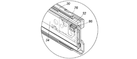
図2に示す通り、スライドレールアセンブリ20は、第一レール30、第二レール32及び第三レール34を備える。
第一レール30は、第一ブラケット26aと第二ブラケット26bを有する。
また、第一レール30は、前端36a、後端36b、及び前端36aと後端36bとの間に位置する第一通路38を有する。
第一レール30は、少なくとも1個の接触部40を有する。
接触部40は、後端36bに隣り合う2個の突出物などである。
As shown in FIG. 2, the
The
The
The
The
本実施形態において、スライドレールアセンブリ20は、第一ブロック部材42と第二ブロック部材44をさらに備える。
第一ブロック部材42は、第一レール30に隣り合う後端36bに配置される。
第二ブロック部材44は、第一レール30から離れた後端36bに配置される。
In the present embodiment, the
The
The
第二レール32は、第一レール30の第一通路38に取り付けられる。
第二レール32は、前端46a、後端46b、及び前端46aと後端46bとの間に位置する第二通路48を有する。
スライドレールアセンブリ20は、第一嵌着メカニズム50、第二嵌着メカニズム52、第三嵌着メカニズム54及び係止台56をさらに備える。
第一嵌着メカニズム50、第二嵌着メカニズム52及び第三嵌着メカニズム54は、それぞれ異なる位置で、第二レール32に取り付けられる。
The
The
The
The first
例えば、第二嵌着メカニズム52の位置は、第一嵌着メカニズム50と第三嵌着メカニズム54との間で、第一嵌着メカニズム50は、第二レール32の後端46bに隣り合う。
第一嵌着メカニズム50は、第一嵌着部材58、及び第一嵌着部材58に弾力を作用する第一弾性部材60を有する。
第二嵌着メカニズム52は、第二嵌着部材62、及び第二嵌着部材62に弾力を作用する第二弾性部材64を有する。
第三嵌着メカニズム54は、第三嵌着部材66、及び第三嵌着部材66に弾力を作用する第三弾性部材68を有する。
For example, the position of the second
The first
The second
The third
スライドレールアセンブリ20は、第一枢接部材70、第二枢接部材72、第一嵌着部材58、第二嵌着部材62、及び第三枢接部材74をさらに備える。
第三枢接部材74は、第三嵌着部材66をそれぞれ第二レール32に枢接する
The
The third pivot member 74 pivots the third
図3に示す通り、係止台56は、第二レール32に配置され、例えば、第二レール32に隣り合う前端46aなどに配置される。
係止台56は、係止部76を有する。
As shown in FIG. 3, the locking
The locking
第三レール34は、第二レール32の第二通路48に取り付けられる。第三レール34により、搭載物22(図示なし)が搭載される。
この部分は領域において通常の知識を有する者なら理解可能な技術範疇であるため、説明を簡略化するため、説明を省く。
The
Since this part is a technical category that can be understood by those who have ordinary knowledge in the field, the description will be omitted to simplify the explanation.
図4と図5に示す通り、第三レール34は、前端78aと後端78bを有する。
第三レール34は、上壁80a、下壁80b、及び上壁80aと下壁80bとの間に連接される縦方向壁82(図4と図5に示す第三レール34は反対であるため、同図が示す上壁80aと下壁80bなどの部品もすべて反対である)を有する。
第三レール34は、後ブロック84と前ブロック86を有する。
後ブロック84は、第三レール34に隣り合う後端78bに位置する。
前ブロック86は、第三レール34に隣り合う前端78aに位置する。
本実施形態において、後ブロック84と前ブロック86とは、突出物を例とする。
As shown in FIGS. 4 and 5, the
The
The
The
The
In the present embodiment, the
スライドレールアセンブリ20は、第一作動部材88、及び第三レール34の縦方向壁82に取り付けられる第二作動部材90をさらに備える。
また、スライドレールアセンブリ20は、、第四枢接部材92及び第五枢接部材94をさらに備える。
第五枢接部材94は、第一作動部材88と第二作動部材90を第三レール34の縦方向壁82にそれぞれ枢接する。
The
The
The
スライドレールアセンブリ20は、弾性台96、第一操作部材98、第二操作部材100、第一補助弾性部材102及び第二補助弾性部材104をさらに備える。
弾性台96は、第三レール34の縦方向壁82に連接し、第一作動部材88の少なくとも1個の部分と第二作動部材90の少なくとも1個の部分を弾性的にサポートする。
第一操作部材98と第二操作部材100とは、第一作動部材88と第二作動部材90とをそれぞれ操作する。
第一補助弾性部材102と第二補助弾性部材104とは、第一操作部材98と第二操作部材100とにそれぞれ弾力を作用する。
The
The
The
The first auxiliary
スライドレールアセンブリ20は、スイッチ部材106をさらに備える。
スイッチ部材106は、第三レール34に取り付けられている。
スイッチ部材106と前ブロック86とは、相互に縦方向距離を隔ており、離間されている。
具体的には、スイッチ部材106は、移動可能に連接され、例えば、第六枢接部材108により第三レール34の縦方向壁82に取り付けられる。
The
The
The
Specifically, the
第三レール34は、サポート特徴110をさらに有する。
スイッチ部材106は、2個のスイッチ特徴112を有する。
スイッチ部材106が異なる位置にある時には、各スイッチ特徴112は、サポート特徴110により対応してサポートされる。
サポート特徴110と2個のスイッチ特徴112とは、凹と凸、凸と凹、或いは凸と凸の対応構造とすることができる。
The
The
Each
The
図6に示す通り、第一嵌着部材58、第二嵌着部材62及び第三嵌着部材66は、第一延伸部113、第二延伸部115、及び第二レール32から伸び出し、第一レール30に対応する第三延伸部117をそれぞれ有する。
第二ブロック部材44は、嵌着解除部114、及び嵌着解除部114から延伸し、一角度の屈折を呈する位置制限部116を有する。
嵌着解除部114は、斜面或いは曲面である。
スライドレールアセンブリ20が収納状態にあると、第二レール32は第一レール30に相対して収納され、しかも第二レール32の後端46bは、第一レール30の少なくとも1個の接触部40に接触し、第一位置P1に位置する。
第三レール34が第二レール32に相対して収納され、第三レール34の前ブロック86は、係止台56の係止部76に接触する(この部分は図7を参照されたい)。
第一嵌着部材58の2個の相対部位は、第一弾性部材60と第三レール34(例えば第三レール34の下壁80b)により、それぞれサポートを提供され、予定状態を保持する。
一方、第二嵌着部材62と第三嵌着部材66とは、第二弾性部材64と第三弾性部材68によりそれぞれ弾力を作用され、予定状態を保持する。
第二嵌着部材62が予定状態にあると、第二嵌着部材62の位置は、第三レール34の後ブロック84に対応する。
本実施形態において、後ブロック84と第二嵌着部材62との間には、一距離を備え、第二嵌着部材62の第二延伸部115の位置は、第二ブロック部材44の嵌着解除部114に対応する。
一方、第三嵌着部材66が予定状態にあると、第三嵌着部材66の第三延伸部117の位置は、第二ブロック部材44の嵌着解除部114に対応する。
As shown in FIG. 6, the first
The
The
When the
The
The two relative portions of the first
On the other hand, the second
When the second
In the present embodiment, a distance is provided between the
On the other hand, when the third
図8に示す通り、第三レール34が第二レール32に相対して第一方向D1へと移動すると、第三レール34は、後ブロック84により、第二嵌着部材62を押す。第二レール32と同期して連動し、第二レール32が第一位置P1から第一方向D1へと移動する。
第三レール34が移動したとき、第三嵌着部材66の第三延伸部117は、第二ブロック部材44の嵌着解除部114により導引され、第二ブロック部材44上に接触する。
これにより、第三弾性部材68は弾力を蓄え、第二嵌着部材62の第二延伸部115は、第二ブロック部材44の嵌着解除部114に接触する。
As shown in FIG. 8, when the
When the
As a result, the third
図9に示す通り、第三レール34がさらに第一方向D1に向かい予定位置まで移動すると、第二ブロック部材44の嵌着解除部114により、第二嵌着部材62を導引して一角度の偏りを呈する。
これにより、第二嵌着部材62は、第三レール34の後ブロック84から離脱し、第二レール32と第三レール34の同期移動関係を解除する。しかも、第二レール32は第一レール30に相対して、第二位置P2にすでに達している。
As shown in FIG. 9, when the
Thereby, the second
一方、第二ブロック部材44を過ぎた後は、第三嵌着部材66は、第三弾性部材68の弾力に反応し、一角度の偏りを呈する。しかも第二ブロック部材44に隣り合う位置制限部116に位置し、これにより第二レール32は一時的に第二位置P2に止まる。
この他、第三レール34は第二レール32に相対して第一方向D1に向かい継続して移動するため、第一嵌着部材58への第三レール34(例えば、第三レール34の下壁80b)によるサポートは解消される。
しかも、第一嵌着部材58は、第一弾性部材60の弾力に反応し一角度の偏りを呈し、第一ブロック部材42に対応する。
On the other hand, after passing the
In addition, since the
In addition, the first
さらに、第三レール34は第二レール32に相対して第一方向D1へと第三位置P3(例えば、延伸位置)まで移動し、しかも第三レール34の前端78aは、第二レール32の前端46aを超過した状態下で、第一レール30、第二レール32及び第三レール34は第一長さL1を形成する。
つまり、第一レール30の後端36bと第三レール34の前端78aとの間には、第一長さL1が形成される。
Further, the
That is, the first length L1 is formed between the
図10に合わせて示す通り、第三レール34が第三位置P3に到達すると、第一作動部材88は、第一作動位置X1において、係止台56の係止部76の一方側S1に接触する。
一方、第三レール34が第三位置P3に到達する過程では、第二作動部材90は、係止台56の係止部76に沿って移動し弾力を生じる。
第二作動部材90は、係止台56の係止部76を越えると、弾力を開放する。これにより第二作動部材90は、第一作動位置Y1において、係止台56の係止部76の他方側S2に接触する。
すなわち、この状態下では、第三レール34は、第二レール32に相対して延伸或いは収納されることはない。
As shown in FIG. 10, when the
On the other hand, in the process in which the
The
That is, under this state, the
図11と図12に示す通り、操作者が力量F1を加え、第二操作部材100を移動させ、第二作動部材90を操作して、第一作動位置Y1から第二作動位置Y2へと一角度の偏りを呈すると、第二作動部材90は他方側S2への接触を解消する。
つまり、この状態下で、第三レール34は、第二レール32に相対して第二方向D2へと収納される。
As shown in FIGS. 11 and 12, the operator applies the force F1, moves the
That is, under this state, the
図13と図14に示す通り、操作者はスイッチ部材106を第一スイッチ位置W1から第二スイッチ位置W2へと操作する。
第一スイッチ位置W1にある時には、スイッチ部材106と係止台56の係止部76とは離れる。
第二スイッチ位置W2にある時には、スイッチ部材106と係止台56の係止部76とは接触している。
As shown in FIGS. 13 and 14, the operator operates the
When in the first switch position W1, the
When in the second switch position W2, the
図14に示す通り、第三レール34が第二レール32に相対して延伸位置から第二方向D2に向かい一位置に移動すると、第三レール34(例えば、第三レール34の下壁80b)は、第三嵌着部材66に接触する。
これにより、第三嵌着部材66は、一角度の偏りを呈し、第二ブロック部材44の位置制限部116を離脱する。
As shown in FIG. 14, when the
As a result, the third
図14と図15に示す通り、第一ブロック部材42は、導引部118と導引部118から延伸し、しかも一角度の屈折を呈する嵌着部120を有する。
導引部118は、斜面或いは曲面である。
第三レール34がさらに第二方向D2に向かい移動すると、第三レール34は、スイッチ部材106により、第二スイッチ位置W2において係止台56の係止部76の他方側S2を押す(この部分は図16を参照されたい)。
これにより、第二レール32は、第三レール34に従い、第二位置P2から第二方向D2へと移動し、しかも第二方向D2へと移動する過程において、導引部118の導引により、第一嵌着部材58は一角度の偏りを呈し、しかも第一弾性部材60の弾力に反応し、第一ブロック部材42の嵌着部120に接触する。
これにより、第二レール32は、収納位置等の第四位置P4を保持する。
この状態下で、第二レール32は、第一レール30に相対して第二方向D2或いは第一方向D1(第二方向D2に反対の方向)へと移動することはできない。
As shown in FIGS. 14 and 15, the
The guiding
When the
Thereby, the
Thereby, the
Under this state, the
スイッチ部材106は、第三レール34の前ブロック86に置換され、係止台56の係止部76の他方側S2に隣り合うため、第三レール34が第二レール32に相対して収納される時、第三レール34の後ブロック84と第二嵌着部材62とはある距離を保持し、第三レール34の移動時には、同期に第二レール32を連動することはできない。
Since the
図17に示す通り、第二レール32が第四位置P4にある状態下では、第三レール34は、第二レール32に相対して、第一作動部材88が係止台56の係止部76の一方側S1に接触するまで第一方向D1へと移動する。
この時、第一レール30の後端36bと第三レール34の前端78aとの間には、第二長さL2が形成され、第二長さL2は、第一長さL1(図9参照)より短い。
すなわち、第二レール32により第一レール30に相対して第四位置P4へと収納されると、第一長さL1は、第二長さL2へと短縮される。
As shown in FIG. 17, when the
At this time, a second length L2 is formed between the
That is, when the
図18と図19に示す通り、第二長さL2の状態下で、操作者が力量F2を加えて第一操作部材98を移動させ、第一作動部材88を操作し、第一作動位置X1から第二作動位置X2へと移動させると、第一作動部材88は、係止台56の係止部76の一方側S1から離脱する。これにより、第三レール34は、第二レール32に相対して取り外される。
As shown in FIGS. 18 and 19, in the state of the second length L2, the operator applies the force F2 to move the
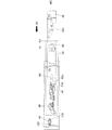
図20に示す通り、限られた空間環境下で、スライドレールアセンブリ20が延伸状態を呈すると、スライドレールアセンブリ20と環境物件122(例えばドア或いは壁)との間には、第一空間d1を有する。
しかし、第一空間d1は、操作者がスライドレールアセンブリ20のメンテナンスを行う、例えば第三レール34を取り外すには、かなり狭い。
As shown in FIG. 20, when the
However, the first space d1 is quite small for the operator to perform maintenance of the
図21に示す通り、操作者は上述の操作方式を利用し、第二レール32を第一レール30に相対して収納させ、しかも一時的に第一レール30に嵌着させる。
これにより、スライドレールアセンブリ20の全体的な長さは短縮される。
この状態下で、スライドレールアセンブリ20と環境物件122との間には、第二空間d2を有する。
第二空間d2は、第一空間d1より大きいため、その十分な空間を操作者は運用でき、スライドレールアセンブリ20のメンテナンス作業、或いは第三レール34を第二レール32から取り外すのに便利である。
As shown in FIG. 21, the operator stores the
This reduces the overall length of the
Under this state, a second space d2 is provided between the
Since the second space d2 is larger than the first space d1, the operator can operate the sufficient space, which is convenient for the maintenance work of the
この他、本発明はスライドレールアセンブリの操作方法を提供する。
方法は、上述の実施形態中に開示しており、説明を簡略化するため、ここでは再度の記述はしない。
In addition, the present invention provides a method for operating a slide rail assembly.
The method is disclosed in the above embodiment and will not be described again here for the sake of simplicity.
前述した本発明の実施形態は本発明を限定するものではなく、よって、本発明により保護される範囲は後述される特許請求の範囲を基準とする。 The embodiments of the present invention described above do not limit the present invention, and therefore the scope protected by the present invention is based on the claims described below.
20 スライドレールアセンブリ、
22 搭載物、
24 シャーシ、
26a 第一ブラケット、
26b 第二ブラケット、
28a 第一シャーシ柱、
28b 第二シャーシ柱、
30 第一レール、
32 第二レール、
34 第三レール、
36a 前端、
36b 後端、
38 第一通路、
40 少なくとも1個の接触部、
42 第一ブロック部材、
44 第二ブロック部材、
46a 前端、
46b 後端、
48 第二通路、
50 第一嵌着メカニズム、
52 第二嵌着メカニズム、
54 第三嵌着メカニズム、
56 係止台、
58 第一嵌着部材、
60 第一弾性部材、
62 第二嵌着部材、
64 第二弾性部材、
66 第三嵌着部材、
68 第三弾性部材、
70 第一枢接部材、
72 第二枢接部材、
74 第三枢接部材、
76 係止部、
78a 前端、
78b 後端、
80a 上壁、
80b 下壁、
82 縦方向壁、
84 後ブロック、
86 前ブロック、
88 第一作動部材、
90 第二作動部材、
92 第四枢接部材、
94 第五枢接部材、
96 弾性台、
98 第一操作部材、
100 第二操作部材、
102 第一補助弾性部材、
104 第二補助弾性部材、
106 スイッチ部材、
108 第六枢接部材、
110 サポート特徴、
112 スイッチ特徴、
113 第一延伸部、
114 嵌着解除部、
115 第二延伸部、
116 位置制限部、
117 第三延伸部、
118 導引部、
120 嵌着部、
122 環境物件、
D1 第一方向、
D2 第二方向、
L1 第一長さ、
L2 第二長さ、
P1 第一位置、
P2 第二位置、
P3 第三位置、
P4 第四位置、
d1 第一空間、
d2 第二空間、
W1 第一スイッチ位置、
W2 第二スイッチ位置、
X1 第一作動位置、
X2 第二作動位置、
Y1 第一作動位置、
Y2 第二作動位置。
20 slide rail assembly,
22 Mounted items,
24 chassis,
26a first bracket,
26b second bracket,
28a first chassis pillar,
28b Second chassis pillar,
30 First rail,
32 Second rail,
34 Third rail,
36a front end,
36b rear end,
38 First passage,
40 at least one contact,
42 first block member,
44 second block member,
46a front end,
46b rear end,
48 Second passage,
50 First fitting mechanism,
52 second fitting mechanism,
54 Third fitting mechanism,
56 Locking base,
58 first fitting member,
60 first elastic member,
62 second fitting member,
64 second elastic member,
66 third fitting member,
68 third elastic member,
70 first pivot member,
72 second pivot member,
74 Third pivotal member,
76 locking part,
78a front end,
78b rear end,
80a upper wall,
80b lower wall,
82 longitudinal walls,
84 back block,
86 Previous block,
88 first actuating member,
90 second actuating member,
92 Fourth pivotal member,
94 Fifth pivotal member,
96 elastic base,
98 first operation member,
100 second operation member,
102 first auxiliary elastic member,
104 second auxiliary elastic member,
106 switch member,
108 sixth pivotal member,
110 Support features,
112 switch features,
113 first stretching part,
114 disengagement part,
115 second stretched part,
116 position limiter,
117 third stretched part,
118 Guide part,
120 fitting part,
122 Environmental properties,
D1 first direction,
D2 second direction,
L1 first length,
L2 second length,
P1 first position,
P2 second position,
P3 third position,
P4 4th position,
d1 first space,
d2 second space,
W1 first switch position,
W2 Second switch position,
X1 first operating position,
X2 second operating position,
Y1 first operating position,
Y2 Second operating position.
Claims (7)
前記第一レールは、前端と後端を有し、
前記第二レールは、前記第一レールに相対して移動し、
前記第三レールは、前記第二レールに相対して移動し、前端と後端を有し、
前記第一嵌着メカニズムは、前記第二レールに移動可能に取り付けられ、
前記第二レールは、前記第一レールに相対して、第一位置から第一方向に向かい、第二位置へと移動し、
前記第三レールは、前記第二レールに相対して、第一方向に向かって第三位置へと移動し、前記第二レールを超過すると、前記第一レールの後端と前記第三レールの前端との間に、第一長さを区画形成し、
前記第二レールが前記第二位置から第二方向に向かって第四位置へと移動するとき、前記第一長さが第二長さへと短縮され、前記第一嵌着メカニズムにより、前記第二レールが前記第一レールに相対して前記第四位置に位置し、
前記第一作動部材は、前記第三レールに取り付けられ、第一作動位置と第二作動位置との間で操作され、
前記係止台は、前記第二レールに取り付けられ、係止部を有し、
前記第三レールが第一方向に向かって第三位置へと移動したとき、前記第一作動部材が前記第一作動位置において前記係止部の一方側に接触し、
前記第一作動部材が前記第一作動位置から前記第二作動位置へと移動するとき、前記第一作動部材が前記係止部と離れ、前記第三レールは前記第二レールに相対して第一方向に移動し、
前記スイッチ部材は、前記第三レールに取り付けられており、第一スイッチ位置、或いは、第二スイッチ位置で操作され、
前記スイッチ部材が前記第一スイッチ位置にあるとき、前記スイッチ部材と前記係止部とが離れ、
前記スイッチ部材が前記第二スイッチ位置にあるとき、前記スイッチ部材と前記係止部とが接触し、
前記第三レールは、前ブロックを有し、
前記前ブロックと前記スイッチ部材とは、離間されており、
前記第一ブロック部材は、前記第一レールに配置されており、
前記第一嵌着メカニズムは、第一嵌着部材、及び前記第一嵌着部材に弾力を作用する第一弾性部材を有し、
前記第三レールが前記第二レールに向かって移動して、前記スイッチ部材と前記係止部とが接触したとき、前記第二レールは、前記第一嵌着メカニズムにより前記第一ブロック部材に接触し、
前記第一嵌着部材は、前記第一弾性部材の弾力により、前記第一ブロック部材に接触し、前記第二レールは、前記第四位置で保持されることを特徴とするスライドレールアセンブリ。 A first rail, a second rail, a third rail, a first fitting mechanism, a first operating member, a locking base, a switch member, and a first block member ;
The first rail has a front end and a rear end;
The second rail moves relative to the first rail;
The third rail moves relative to the second rail and has a front end and a rear end;
The first fitting mechanism is movably attached to the second rail,
The second rail is moved from the first position to the first direction relative to the first rail, and moved to the second position.
The third rail moves to the third position in the first direction relative to the second rail, and when the second rail is exceeded, the rear end of the first rail and the third rail A first length is defined between the front end and
When the second rail moves from the second position to the fourth position in the second direction, the first length is shortened to the second length, and the first fitting mechanism Two rails are located in the fourth position relative to the first rail;
The first operating member is attached to the third rail and is operated between a first operating position and a second operating position;
The locking base is attached to the second rail, has a locking portion,
When the third rail moves to the third position in the first direction, the first operating member contacts one side of the locking portion at the first operating position,
When the first actuating member moves from the first actuating position to the second actuating position, the first actuating member is separated from the locking portion, and the third rail is opposed to the second rail. Move in one direction,
The switch member is attached to the third rail, and is operated at a first switch position or a second switch position.
When the switch member is in the first switch position, the switch member and the locking portion are separated,
When the switch member is in the second switch position, the switch member and the locking portion are in contact with each other,
The third rail has a front block;
The front block and the switch member are separated from each other,
The first block member is disposed on the first rail,
The first fitting mechanism has a first fitting member, and a first elastic member that acts elastically on the first fitting member,
When the third rail moves toward the second rail and the switch member comes into contact with the locking portion, the second rail contacts the first block member by the first fitting mechanism. And
The slide rail assembly, wherein the first fitting member contacts the first block member by the elasticity of the first elastic member, and the second rail is held at the fourth position.
前記第三レールが第一方向に向かって第三位置へと移動したとき、前記第二作動部材が、前記係止部に沿って移動し、
前記第二作動部材が前記係止部を越えたとき、前記第二作動部材は、前記係止部の他方側に接触することを特徴とする請求項1に記載のスライドレールアセンブリ。 A second actuating member attached to the third rail to have elasticity;
When the third rail moves to the third position in the first direction, the second actuating member moves along the locking portion,
When said second actuating member exceeds the locking portion, the second actuating member, the slide rail assembly according to claim 1, characterized in that contacts the other side of the locking portion.
前記第二ブロック部材は、前記第一レールに配置され、嵌着解除部を有し、
前記第二嵌着メカニズムは、前記第二レールに移動可能に取り付けられ、第二嵌着部材、及び前記第二嵌着部材に弾力を作用する第二弾性部材を有し、
前記第三レールは、後ブロックを有し、
前記第三レールが、前記後ブロックにより前記第二嵌着メカニズムを押し、前記第二レールと同期して連動し、前記第一位置から第一方向に向かって移動し、予定位置まで移動するとき、前記嵌着解除部により、前記第二嵌着メカニズムが前記後ブロックから離脱することを特徴とする請求項1に記載のスライドレールアセンブリ。 A second block member and a second fitting mechanism;
The second block member is disposed on the first rail and has a fitting release portion.
The second fitting mechanism is movably attached to the second rail, has a second fitting member, and a second elastic member that acts elastically on the second fitting member,
The third rail has a rear block;
When the third rail pushes the second fitting mechanism by the rear block, interlocks with the second rail, moves in the first direction from the first position, and moves to the planned position , by the fitted and release unit, the slide rail assembly of claim 1, wherein the second fitting mechanism, characterized in that separated from the rear block.
前記第二ブロック部材は、位置制限部をさらに有し、
前記第三嵌着メカニズムは、第三嵌着部材、及び前記第三嵌着部材に弾力を作用する第三弾性部材を有し、
前記第二レールが前記第二位置へと移動するとき、
前記第三嵌着メカニズムは、前記位置制限部に隣り合うように位置し、
前記第三嵌着部材は、前記第三弾性部材の弾力に反応し、前記位置制限部に位置することを特徴とする請求項3に記載のスライドレールアセンブリ。 A third fitting mechanism movably attached to the second rail;
The second block member further has a position limiting portion,
The third fitting mechanism has a third fitting member, and a third elastic member that acts elastically on the third fitting member,
When the second rail moves to the second position,
The third fitting mechanism is located adjacent to the position limiting portion ,
4. The slide rail assembly according to claim 3 , wherein the third fitting member is positioned at the position limiting portion in response to the elasticity of the third elastic member.
前記スライドレールアセンブリは、第一レール、第二レール、第三レール、第一ブロック部材、第一嵌着メカニズム、第一作動部材、係止部及びスイッチ部材を備え、
前記第一レールは、前記シャーシに取り付けられ、前端と後端を有し、
前記第二レールは、前記第一レールに相対して移動し、
前記第三レールは、前記第二レールに相対して移動し、前記搭載物を搭載し、前端と後端を有し、
前記第一ブロック部材は、前記第一レールに配置され、
前記第一嵌着メカニズムは、前記第二レールに移動可能に取り付けられ、
前記第一作動部材は、前記第三レールに取り付けられ、第一作動位置と第二作動位置との間で操作され、
前記第二レールは、前記第一レールに相対して、第一位置から第一方向に向かい、第二位置へと移動し、
前記第三レールは、前記第二レールに相対して、第一方向に向かって第三位置へと移動し、前記第二レールを超過すると、前記第一レールの後端と前記第三レールの前端との間に、第一長さが区画形成し、
前記第二レールが前記第二位置から第二方向に向かって第四位置へと移動するとき、前記第一長さが第二長さへと短縮され、前記第一嵌着メカニズムにより、前記第二レールが前記第一レールに相対して前記第四位置に位置し、
前記第一作動部材が操作され、前記第一作動位置から前記第二作動位置へと移動するとき、前記第三レールは、前記第二レールに相対して第一方向に移動し、
前記スイッチ部材は、前記第三レールに取り付けられており、第一スイッチ位置、或いは、第二スイッチ位置で操作され、
前記スイッチ部材が前記第一スイッチ位置にあるとき、前記スイッチ部材と前記係止部とが離れ、
前記スイッチ部材が前記第二スイッチ位置にあるとき、前記スイッチ部材と前記係止部とが接触し、
前記第三レールは、前ブロックを有し、
前記前ブロックと前記スイッチ部材とは、離間されており、
前記第一ブロック部材は、前記第一レールに配置されており、
前記第一嵌着メカニズムは、第一嵌着部材、及び前記第一嵌着部材に弾力を作用する第一弾性部材を有し、
前記第三レールが前記第二レールに向かって移動して、前記スイッチ部材と前記係止部とが接触したとき、前記第二レールは、前記第一嵌着メカニズムにより前記第一ブロック部材に接触し、
前記第一嵌着部材は、前記第一弾性部材の弾力により、前記第一ブロック部材に接触し、前記第二レールは、前記第四位置で保持されることを特徴とするスライドレールアセンブリ。 The slide rail assembly is used to attach the load to the chassis,
The slide rail assembly includes a first rail, a second rail, a third rail, a first block member, a first fitting mechanism, a first operating member, a locking portion, and a switch member .
The first rail is attached to the chassis and has a front end and a rear end;
The second rail moves relative to the first rail;
The third rail moves relative to the second rail, carries the load, and has a front end and a rear end;
The first block member is disposed on the first rail,
The first fitting mechanism is movably attached to the second rail,
The first operating member is attached to the third rail and is operated between a first operating position and a second operating position;
The second rail relative to the first rail, directed from a first position in a first direction, to move to a second position,
The third rail, relative to the second rail, toward the first direction moves to the third position, if it exceeds the second rail, and the rear end of the first rail of the third rail between the front end, the first length is defined and formed,
When the second rail moves from the second position to the fourth position in the second direction, the first length is shortened to the second length, and the first fitting mechanism Two rails are located in the fourth position relative to the first rail;
When the first operating member is operated and moved from the first operating position to the second operating position, the third rail moves in a first direction relative to the second rail ;
The switch member is attached to the third rail, and is operated at a first switch position or a second switch position.
When the switch member is in the first switch position, the switch member and the locking portion are separated,
When the switch member is in the second switch position, the switch member and the locking portion are in contact with each other,
The third rail has a front block;
The front block and the switch member are separated from each other,
The first block member is disposed on the first rail,
The first fitting mechanism has a first fitting member, and a first elastic member that acts elastically on the first fitting member,
When the third rail moves toward the second rail and the switch member comes into contact with the locking portion, the second rail contacts the first block member by the first fitting mechanism. And
The slide rail assembly, wherein the first fitting member contacts the first block member by the elasticity of the first elastic member, and the second rail is held at the fourth position .
前記第一レールは、前端と後端を有し、
前記第二レールは、前記第一レールに相対して移動し、
前記第三レールは、前記第二レールに相対して移動し、前端、後端、及び、前記スイッチ部材とは離間されている前ブロックを有し、
前記第一嵌着メカニズムは、前記第二レールに移動可能に取り付けられ、第一嵌着部材、及び前記第一嵌着部材に弾力を作用する第一弾性部材を有し、
前記第一作動部材は、前記第三レールに取り付けられ、第一作動位置と第二作動位置との間で操作され、
前記係止台は、係止部を有し、
前記第一ブロック部材は、前記第一レールに配置されているスライドレールアセンブリの操作方法であって、
前記第二レールを、前記第一レールに相対して、第一位置から第一方向に向かって第二位置へと移動させ、
前記第三レールを、前記第二レールに相対して、第一方向に向かって第三位置へと移動させ、前記第三レールが前記第二レールを超過するとき、前記第一レールの後端と前記第三レールの前端との間に、第一長さを区画形成し、
前記第二レールを、前記第二位置から第二方向に向かって第四位置へと移動させるとき、前記第一長さを第二長さへと短縮させ、前記第一嵌着メカニズムを用いて、前記第二レールを前記第一レールに相対して前記第四位置に移動させ、
前記第一長さが第二長さに短縮されているとき、前記第一作動部材を前記第一作動位置から前記第二作動位置まで操作し、前記第三レールが前記第二レールに相対して取り外され、
前記係止台を前記第二レールに取り付け、
前記第三レールを第一方向に向かって第三位置へと移動させ、前記第一作動部材を前記第一作動位置において前記係止部の一方側に接触させ、
前記第一作動部材を前記第一作動位置から前記第二作動位置へと移動させるとき、前記第一作動部材が前記係止部と離れ、前記第三レールは前記第二レールに相対して第一方向に移動し、
前記スイッチ部材を前記第三レールに取り付け、第一スイッチ位置、或いは、第二スイッチ位置で操作し、
前記スイッチ部材が前記第一スイッチ位置にあるとき、前記スイッチ部材と前記係止部とが離れ、
前記スイッチ部材が前記第二スイッチ位置にあるとき、前記スイッチ部材と前記係止部とが接触し、
前記第三レールを前記第二レールに向かって移動させ、前記スイッチ部材と前記係止部とが接触したとき、前記第二レールは、前記第一嵌着メカニズムにより前記第一ブロック部材に接触し、
前記第一嵌着部材は、前記第一弾性部材の弾力により、前記第一ブロック部材に接触し、前記第二レールは、前記第四位置で保持されることを特徴とするスライドレールアセンブリの操作方法。 A first rail, a second rail, a third rail, a first fitting mechanism, a first operating member, a locking base, a switch member, and a first block member ;
The first rail has a front end and a rear end;
The second rail moves relative to the first rail;
The third rail has a front block that moves relative to the second rail and is separated from the front end, the rear end, and the switch member ;
The first fitting mechanism is movably attached to the second rail, has a first fitting member, and a first elastic member that exerts elasticity on the first fitting member,
The first operating member is attached to the third rail and is operated between a first operating position and a second operating position ;
The locking base has a locking portion,
The first block member is a method of operating a slide rail assembly disposed on the first rail ,
Moving the second rail relative to the first rail from the first position to the second position in the first direction;
The third rail is moved to a third position in the first direction relative to the second rail, and when the third rail exceeds the second rail, the rear end of the first rail and between the front end of the third rail, to define a first length,
When the second rail is moved from the second position to the fourth position in the second direction, the first length is shortened to the second length, and the first fitting mechanism is used. Moving the second rail to the fourth position relative to the first rail;
When the first length is shortened to the second length, the first operating member is operated from the first operating position to the second operating position, and the third rail is opposed to the second rail. Removed ,
Attaching the locking base to the second rail,
Moving the third rail in the first direction to a third position, bringing the first operating member into contact with one side of the locking portion at the first operating position;
When the first actuating member is moved from the first actuating position to the second actuating position, the first actuating member is separated from the locking portion, and the third rail is opposed to the second rail. Move in one direction,
The switch member is attached to the third rail and operated at the first switch position or the second switch position,
When the switch member is in the first switch position, the switch member and the locking portion are separated,
When the switch member is in the second switch position, the switch member and the locking portion are in contact with each other,
When the third rail is moved toward the second rail and the switch member comes into contact with the locking portion, the second rail comes into contact with the first block member by the first fitting mechanism. ,
The operation of the slide rail assembly, wherein the first fitting member contacts the first block member by the elasticity of the first elastic member, and the second rail is held at the fourth position. Method.
前記第二レールが前記第四位置にあるとき、前記第一嵌着メカニズムを用いて前記第二レールと前記第一ブロック部材とを接触させることを特徴とする請求項6に記載のスライドレールアセンブリの操作方法。 When the third rail is moved in the first direction, the first operating member contacts one side of the locking portion at the first operating position;
The slide rail assembly according to claim 6 , wherein when the second rail is in the fourth position, the second rail and the first block member are brought into contact with each other using the first fitting mechanism. How to operate.
Applications Claiming Priority (2)
| Application Number | Priority Date | Filing Date | Title |
|---|---|---|---|
| TW105102163A TWI568382B (en) | 2016-01-22 | 2016-01-22 | Slide rail assembly and operation method thereof |
| TW105102163 | 2016-01-22 |
Publications (2)
| Publication Number | Publication Date |
|---|---|
| JP2017127625A JP2017127625A (en) | 2017-07-27 |
| JP6412537B2 true JP6412537B2 (en) | 2018-10-24 |
Family
ID=57288138
Family Applications (1)
| Application Number | Title | Priority Date | Filing Date |
|---|---|---|---|
| JP2016214297A Active JP6412537B2 (en) | 2016-01-22 | 2016-11-01 | Slide rail assembly and operating method thereof |
Country Status (4)
| Country | Link |
|---|---|
| US (1) | US9992906B2 (en) |
| EP (1) | EP3195760B1 (en) |
| JP (1) | JP6412537B2 (en) |
| TW (1) | TWI568382B (en) |
Families Citing this family (24)
| Publication number | Priority date | Publication date | Assignee | Title |
|---|---|---|---|---|
| US10213017B2 (en) * | 2016-10-05 | 2019-02-26 | King Slide Works Co., Ltd. | Slide rail assembly |
| TWI646924B (en) * | 2017-09-20 | 2019-01-11 | 振躍精密滑軌股份有限公司 | Slide rail device with middle rail unlocking function |
| TWI646923B (en) * | 2017-11-27 | 2019-01-11 | 川湖科技股份有限公司 | Slide rail assembly and rail assembly |
| TWI658803B (en) * | 2017-12-28 | 2019-05-11 | 川湖科技股份有限公司 | Slide rail assembly and rail kit thereof |
| TWI670029B (en) * | 2018-03-08 | 2019-09-01 | 川湖科技股份有限公司 | Slide rail assembly |
| TWI687178B (en) * | 2018-05-07 | 2020-03-11 | 川湖科技股份有限公司 | Slide rail assembly and slide rail kit thereof |
| CN110464143A (en) * | 2018-05-11 | 2019-11-19 | 川湖科技股份有限公司 | Sliding rail assembly and its sliding rail external member |
| TWI670030B (en) | 2018-09-10 | 2019-09-01 | 川湖科技股份有限公司 | Slide rail assembly |
| US10736422B2 (en) | 2018-10-04 | 2020-08-11 | King Slide Works Co., Ltd. | Slide rail assembly |
| TWI689238B (en) * | 2019-02-01 | 2020-03-21 | 勤誠興業股份有限公司 | Server device and its latch mechanism |
| TWI702019B (en) | 2019-05-06 | 2020-08-21 | 川湖科技股份有限公司 | Slide rail assembly |
| TWI700057B (en) | 2019-06-12 | 2020-08-01 | 川湖科技股份有限公司 | Slide rail assembly and operation method thereof |
| CN112089231B (en) * | 2019-06-17 | 2022-08-12 | 川湖科技股份有限公司 | Slide rail assembly and operation method thereof |
| TWI704888B (en) * | 2019-07-12 | 2020-09-21 | 川湖科技股份有限公司 | Slide rail assembly |
| TWI702018B (en) * | 2019-07-12 | 2020-08-21 | 川湖科技股份有限公司 | Slide rail assembly |
| TWI706751B (en) | 2019-08-14 | 2020-10-11 | 川湖科技股份有限公司 | Slide rail assembly |
| TWI704890B (en) * | 2019-10-18 | 2020-09-21 | 川湖科技股份有限公司 | Slide rail assembly and rail kit thereof |
| TWI704889B (en) | 2019-10-28 | 2020-09-21 | 川湖科技股份有限公司 | Slide rail assembly |
| TWI706749B (en) * | 2019-11-18 | 2020-10-11 | 川湖科技股份有限公司 | Slide rail assembly |
| TWI706752B (en) * | 2019-11-18 | 2020-10-11 | 川湖科技股份有限公司 | Slide rail assembly |
| TWI742835B (en) | 2020-09-01 | 2021-10-11 | 川湖科技股份有限公司 | Slide rail assembly and slide rail kit thereof |
| TWI737555B (en) | 2020-12-22 | 2021-08-21 | 川湖科技股份有限公司 | Slide rail assembly and slide rail kit thereof |
| TWI750987B (en) * | 2020-12-30 | 2021-12-21 | 川湖科技股份有限公司 | Slide rail assembly |
| TWI738613B (en) * | 2021-02-01 | 2021-09-01 | 川湖科技股份有限公司 | Slide rail assembly |
Family Cites Families (23)
| Publication number | Priority date | Publication date | Assignee | Title |
|---|---|---|---|---|
| US6655763B2 (en) | 2000-12-22 | 2003-12-02 | Jonathan Engineered Solutions | Controller for a quick disconnect slide assembly |
| TWI233342B (en) | 2001-10-12 | 2005-06-01 | Accuride Int Inc | Three member thin drawer slide |
| TW589968U (en) * | 2003-03-05 | 2004-06-01 | King Slide Works Co Ltd | Two-way retainer for a sliding track assembly of drawers |
| US7101081B2 (en) * | 2004-10-12 | 2006-09-05 | King Slide Works Co., Ltd. | Positioning device for a ball bearing slide |
| US6997529B1 (en) | 2005-01-19 | 2006-02-14 | King Slide Works Co., Ltd. | Synchronizing device for a tri-sector slide |
| TWI261509B (en) * | 2005-06-24 | 2006-09-11 | King Slide Works Co Ltd | Positioning device for a tri-sector slide |
| CN100591242C (en) * | 2006-12-15 | 2010-02-24 | 鸿富锦精密工业(深圳)有限公司 | Slideway device |
| CN101332022B (en) * | 2007-06-27 | 2010-11-10 | 鸿富锦精密工业(深圳)有限公司 | Slideway device |
| US7896452B2 (en) * | 2008-02-06 | 2011-03-01 | Nan Juen International Co., Ltd. | Slide braking apparatus |
| JP5280732B2 (en) * | 2008-04-25 | 2013-09-04 | 日本アキュライド株式会社 | Slide rail |
| TW201018369A (en) * | 2008-10-16 | 2010-05-01 | Ablecom Technology Inc | Ultra-thin fast assembling/ disassembling slide track |
| TWI402046B (en) * | 2009-04-10 | 2013-07-21 | King Slide Works Co Ltd | Elastic mechanism for a slide assembly |
| CN102210517A (en) * | 2010-04-06 | 2011-10-12 | 鸿富锦精密工业(深圳)有限公司 | Sliding rail mounting mechanism and sliding rail combination using same |
| CN102238841A (en) * | 2010-04-27 | 2011-11-09 | 鸿富锦精密工业(深圳)有限公司 | Slide rail mechanism |
| CN102404962B (en) * | 2010-09-13 | 2016-03-02 | 鸿富锦精密工业(深圳)有限公司 | Railroad |
| CN102548332B (en) * | 2010-12-24 | 2016-06-01 | 中山市云创知识产权服务有限公司 | Railroad |
| TW201309231A (en) | 2011-08-16 | 2013-03-01 | Hon Hai Prec Ind Co Ltd | Slide rail locking apparatus |
| JP5734890B2 (en) * | 2012-02-15 | 2015-06-17 | シロキ工業株式会社 | Slide rail device for vehicle |
| US8801120B2 (en) * | 2012-09-12 | 2014-08-12 | King Slide Works Co., Ltd. | Self-opening and self-closing slide assembly |
| TWI586250B (en) * | 2014-06-18 | 2017-06-01 | 川湖科技股份有限公司 | Slide rail assembly |
| TWI517812B (en) * | 2014-11-04 | 2016-01-21 | King Slide Works Co Ltd | Slide rail assembly |
| US9328769B1 (en) | 2015-01-27 | 2016-05-03 | King Slide Works Co., Ltd. | Slide rail assembly and bracket device thereof |
| TWM510592U (en) * | 2015-05-29 | 2015-10-11 | Chi-Feng Hsu | Slide assembly |
-
2016
- 2016-01-22 TW TW105102163A patent/TWI568382B/en active
- 2016-10-18 US US15/296,326 patent/US9992906B2/en active Active
- 2016-10-24 EP EP16195237.9A patent/EP3195760B1/en active Active
- 2016-11-01 JP JP2016214297A patent/JP6412537B2/en active Active
Also Published As
| Publication number | Publication date |
|---|---|
| TWI568382B (en) | 2017-02-01 |
| EP3195760A1 (en) | 2017-07-26 |
| EP3195760B1 (en) | 2019-03-13 |
| JP2017127625A (en) | 2017-07-27 |
| US9992906B2 (en) | 2018-06-05 |
| US20170208942A1 (en) | 2017-07-27 |
| TW201726032A (en) | 2017-08-01 |
Similar Documents
| Publication | Publication Date | Title |
|---|---|---|
| JP6412537B2 (en) | Slide rail assembly and operating method thereof | |
| JP6663393B2 (en) | Slide rail assembly | |
| JP6715797B2 (en) | Slide rail assembly | |
| US10342341B2 (en) | Slide rail assembly | |
| JP6490722B2 (en) | Slide rail assembly | |
| JP2018187347A (en) | Slide rail assembly | |
| US10617208B2 (en) | Slide rail assembly | |
| TWI700057B (en) | Slide rail assembly and operation method thereof | |
| JP6310995B2 (en) | Slide rail device | |
| US10398228B2 (en) | Slide rail assembly | |
| JP6941710B2 (en) | Slide rail assembly | |
| JP2018061827A (en) | Bracket device | |
| JP6724075B2 (en) | Slide rail assembly | |
| TWI620535B (en) | Slide rail assembly | |
| JP2021079073A (en) | Slide rail assembly | |
| JP2019034111A (en) | Slide rail assembly and rail kit thereof | |
| CN112089231B (en) | Slide rail assembly and operation method thereof | |
| JP3193841U (en) | Slide rail kit | |
| JP2021058568A (en) | Cabinet and slide rail kit thereof | |
| CN114680489B (en) | Slide rail assembly and slide rail external member thereof | |
| CN109419190B (en) | Slide rail assembly and slide rail external member thereof | |
| JP4648796B2 (en) | Locking structure for elastic members | |
| JP4981591B2 (en) | Slide rail |
Legal Events
| Date | Code | Title | Description |
|---|---|---|---|
| A977 | Report on retrieval |
Free format text: JAPANESE INTERMEDIATE CODE: A971007 Effective date: 20180125 |
|
| A131 | Notification of reasons for refusal |
Free format text: JAPANESE INTERMEDIATE CODE: A131 Effective date: 20180206 |
|
| A521 | Request for written amendment filed |
Free format text: JAPANESE INTERMEDIATE CODE: A523 Effective date: 20180413 |
|
| TRDD | Decision of grant or rejection written | ||
| A01 | Written decision to grant a patent or to grant a registration (utility model) |
Free format text: JAPANESE INTERMEDIATE CODE: A01 Effective date: 20180911 |
|
| A61 | First payment of annual fees (during grant procedure) |
Free format text: JAPANESE INTERMEDIATE CODE: A61 Effective date: 20180928 |
|
| R150 | Certificate of patent or registration of utility model |
Ref document number: 6412537 Country of ref document: JP Free format text: JAPANESE INTERMEDIATE CODE: R150 |
|
| R250 | Receipt of annual fees |
Free format text: JAPANESE INTERMEDIATE CODE: R250 |
|
| R250 | Receipt of annual fees |
Free format text: JAPANESE INTERMEDIATE CODE: R250 |
|
| R250 | Receipt of annual fees |
Free format text: JAPANESE INTERMEDIATE CODE: R250 |