JP6411136B2 - Disc-shaped grinding wheel - Google Patents
Disc-shaped grinding wheel Download PDFInfo
- Publication number
- JP6411136B2 JP6411136B2 JP2014175323A JP2014175323A JP6411136B2 JP 6411136 B2 JP6411136 B2 JP 6411136B2 JP 2014175323 A JP2014175323 A JP 2014175323A JP 2014175323 A JP2014175323 A JP 2014175323A JP 6411136 B2 JP6411136 B2 JP 6411136B2
- Authority
- JP
- Japan
- Prior art keywords
- grindstone
- shaped
- disc
- moving
- axial direction
- Prior art date
- Legal status (The legal status is an assumption and is not a legal conclusion. Google has not performed a legal analysis and makes no representation as to the accuracy of the status listed.)
- Active
Links
Images


Classifications
-
- B—PERFORMING OPERATIONS; TRANSPORTING
- B24—GRINDING; POLISHING
- B24D—TOOLS FOR GRINDING, BUFFING OR SHARPENING
- B24D7/00—Bonded abrasive wheels, or wheels with inserted abrasive blocks, designed for acting otherwise than only by their periphery, e.g. by the front face; Bushings or mountings therefor
- B24D7/06—Bonded abrasive wheels, or wheels with inserted abrasive blocks, designed for acting otherwise than only by their periphery, e.g. by the front face; Bushings or mountings therefor with inserted abrasive blocks, e.g. segmental
- B24D7/066—Grinding blocks; their mountings or supports
-
- B—PERFORMING OPERATIONS; TRANSPORTING
- B24—GRINDING; POLISHING
- B24D—TOOLS FOR GRINDING, BUFFING OR SHARPENING
- B24D7/00—Bonded abrasive wheels, or wheels with inserted abrasive blocks, designed for acting otherwise than only by their periphery, e.g. by the front face; Bushings or mountings therefor
- B24D7/18—Wheels of special form
Description
本発明は、例えば、クランクシャフトなどの軸物研削において用いられる円盤状砥石に関する。 The present invention relates to a disc-shaped grindstone used for grinding a shaft object such as a crankshaft, for example.
従来、クランクシャフトのピン部、ジャーナル部の研削加工に用いられる円盤状砥石が知られている(例えば、特許文献1参照)。円盤状砥石は、回転させることにより外周面でクランクシャフトなどの軸物を研削する。 Conventionally, a disc-shaped grindstone used for grinding a pin portion and a journal portion of a crankshaft is known (see, for example, Patent Document 1). A disk-shaped grindstone grinds shaft objects, such as a crankshaft, on an outer peripheral surface by rotating.
同一の研削加工ラインで複数機種の研削加工を行う場合、機種が変わるごとに軸物などの仕様も変化し、研削する円盤状砥石も交換が必要となる場合がある。しかしながら、円盤状砥石は比較的重く、また付帯設備等を用いた交換作業となるため、手間が掛かる。また、円盤状砥石を研削装置に取り付けた後も、円盤状砥石のバランス調整やドレス作業を実施する必要があるため、機種変更のたびに多くの時間を必要とする。 When multiple types of grinding are performed on the same grinding line, the specifications of shafts and the like change with each model change, and the disc-shaped grindstone to be ground may need to be replaced. However, the disk-shaped grindstone is comparatively heavy, and it takes time and effort because it requires replacement work using incidental equipment. Further, even after the disc-shaped grindstone is attached to the grinding apparatus, it is necessary to adjust the balance of the disc-shaped grindstone and to perform dressing work. Therefore, it takes a lot of time each time the model is changed.
本発明は、以上の点に鑑み、交換することなく複数種に対応可能な円盤状砥石を提供することを目的とする。 An object of this invention is to provide the disk shaped grindstone which can respond | correspond to multiple types, without replacing | exchanging in view of the above point.
[1]上記目的を達成するため、本発明は、
円盤状基材の外周面に周方向に分割された分割砥石を複数設けて構成される円盤状砥石であって、少なくとも一部の分割砥石が前記円盤状基材の軸方向に移動可能な移動砥石であり、
前記分割砥石の軸方向の角部は、曲面形状に形成され、
前記移動砥石と前記移動砥石以外の他の分割砥石とでは、軸方向の角部の曲率半径が夫々異なり、
前記他の分割砥石の軸方向の両角部の曲率半径は同一であり、
前記移動砥石は軸方向に隣接させて複数設けられており、
前記移動砥石の他の移動砥石に隣接しない軸方向角部同士の曲率半径は同一であることを特徴とする。
[1] In order to achieve the above object, the present invention provides:
A disc-shaped grindstone configured by providing a plurality of divided grindstones divided in the circumferential direction on the outer peripheral surface of a disc-shaped base material, wherein at least a part of the grindstone is movable in the axial direction of the disc-shaped base material grindstone der is,
The axial corners of the divided grindstone are formed in a curved surface shape,
In the moving grindstone and other divided grindstones other than the moving grindstone, the curvature radii of the corners in the axial direction are different, respectively.
The curvature radii of both corners in the axial direction of the other divided grindstone are the same,
A plurality of the moving grindstones are provided adjacent to each other in the axial direction,
The radius of curvature of the axial angle portions not adjacent to other mobile grinding of the moving grinding wheel is characterized by the same der Rukoto.
本発明によれば、分割砥石の一部が軸方向に移動可能な移動砥石であるため、移動砥石を軸方向に移動させることにより円盤状砥石の幅を変化させることができる。これにより、本発明の円盤状砥石によれば、交換することなく迅速に複数種に対応することができる。 According to the present invention, since a part of the divided grindstone is a movable grindstone that can move in the axial direction, the width of the disc-shaped grindstone can be changed by moving the movable grindstone in the axial direction. Thereby, according to the disk-shaped grindstone of this invention, it can respond to multiple types rapidly, without replacing | exchanging.
[2]また、本発明においては、分割砥石のうち円盤状基材に軸方向に移動不能に固定された分割砥石を固定砥石として、移動砥石と固定砥石とで、軸方向の角部の曲率半径を夫々異ならせることが好ましい。かかる構成によれば、要求される角部の曲率半径が異なる種類の加工にも対応することができる。 [2] In the present invention, as a fixed grinding divided grindstone that is immovably secured in the axial direction into a disc-shaped substrate of the split grindstone, in a moving grindstone and the fixed grinding wheel, the axial corner portions of the It is preferable that the curvature radii are different. According to such a configuration, it is possible to deal with types of processing that require different corner radii of curvature.
[3]また、本発明においては、移動砥石を軸方向に隣接させて複数設け、移動砥石の軸方向端面を円盤状基材の軸方向に対して傾斜する傾斜面とすることができる。かかる構成によれば、移動砥石の移動によって軸方向で隣接する移動砥石の間に隙間が生じても、隙間による研削効率の低下を抑制することができる。 [ 3 ] In the present invention, a plurality of moving grindstones are provided adjacent to each other in the axial direction, and the axial end surface of the moving grindstone can be an inclined surface that is inclined with respect to the axial direction of the disk-shaped substrate. According to this configuration, even if a gap is generated between the moving grindstones adjacent in the axial direction due to the movement of the moving grindstone, it is possible to suppress a reduction in grinding efficiency due to the gap.
[4]また、本発明においては、移動砥石を周方向に複数設け、移動砥石の分割面を夫々ずらしてもよい。かかる構成によれば、移動砥石の移動によって隙間が生じても、隙間の発生個所が分散され、隙間による研削効率の低下を抑制することができる。 [ 4 ] In the present invention, a plurality of moving grindstones may be provided in the circumferential direction, and the divided surfaces of the moving grindstones may be shifted. According to such a configuration, even if a gap is generated due to the movement of the moving grindstone, the places where the gap is generated are dispersed, and a reduction in grinding efficiency due to the gap can be suppressed.
[5]また、本発明においては、移動砥石を、軸方向に2分割された2分割砥石と、軸方向に3分割された3分割砥石とで構成することができる。かかる構成によれば、移動砥石の移動によって隙間が生じても、隙間の発生個所が分散され、隙間による研削効率の低下を抑制することができる。 [ 5 ] In the present invention, the moving grindstone can be constituted by a two-part grindstone divided into two in the axial direction and a three-part grindstone divided into three in the axial direction. According to such a configuration, even if a gap is generated due to the movement of the moving grindstone, the places where the gap is generated are dispersed, and a reduction in grinding efficiency due to the gap can be suppressed.
[6]また、本発明においては、移動砥石の軸方向への移動量を調整自在な調整ネジを設けることができる。 [ 6 ] In the present invention, an adjustment screw capable of adjusting the amount of movement of the moving grindstone in the axial direction can be provided.
[7]また、本発明においては、固定砥石を板状とし、移動砥石を板状の固定砥石を軸方向から挟み込む一対の可動板で構成して、固定砥石と可動板との間には周方向に向かって徐々に厚さが変化するテーパ部が設けられ、固定砥石と可動板とを相対回転させることにより、テーパ部によって一対の可動板同士の間の間隔を変化させて、軸方向の幅を変更するように構成することができる。 [ 7 ] In the present invention, the fixed grindstone is plate-shaped and the moving grindstone is composed of a pair of movable plates sandwiching the plate-shaped fixed grindstone from the axial direction. A taper portion whose thickness gradually changes in the direction is provided, and by rotating the fixed grindstone and the movable plate relative to each other, the interval between the pair of movable plates is changed by the taper portion. It can be configured to change the width.
[第1実施形態]
図1に本発明の第1実施形態の円盤状砥石1を用いた研削装置2を示す。この研削装置2は、軸物としてのクランクシャフトSのピン部を研削するものである。
[First Embodiment]
FIG. 1 shows a
図2に第1実施形態の円盤状砥石1を示す。第1実施形態の円盤状砥石1は、円盤状基材3と、円盤状基材3の外周面に複数設けられた分割砥石4とで構成される。分割砥石4は、円盤状基材3に対して移動不能に固定された固定砥石5と、円盤状基材3に対して軸方向に移動可能な移動砥石6とで構成される。固定砥石5と、移動砥石6とは、円盤状基材3の周方向に交互に配置される。
FIG. 2 shows a disk-shaped
図3に示すように、移動砥石6は、円盤状基材3の軸方向に並べて配置された一対の移動基材7と、各移動基材7の外面に夫々接着された砥石本体8とで構成される。移動基材7には、円盤状基材3側に向かって延びる突片9が設けられている。円盤状基材3の外周面には、突片9を受け入れる受入穴10が設けられている。
As shown in FIG. 3, the moving
円盤状基材3には、受入穴10を横切るように軸方向に貫通する貫通孔11が穿設されている。突片9には、貫通孔11に対応させて軸方向に貫通する貫通孔9aが設けられている。突片9の貫通孔9aは、円盤状基材3の貫通孔11よりも若干径が大きくなるように形成されている。円盤状基材3の貫通孔11には、突片9の貫通孔9aを通ってガイドピン12が圧入されている。
The disk-shaped
移動砥石6はガイドピン12に沿って円盤状基材3の軸方向に移動自在となる。なお、ガイドピン12は、1つの移動砥石6に対して円盤状基材3の周方向に間隔を存して2つ設けられている。
The moving
移動基材7の突片9には、2つのガイドピン12が夫々挿通される2つの貫通孔9aの間に位置させてネジ孔9bが設けられている。ネジ孔9bには、頭部に六角穴13aを有する調整ネジ13が螺着されている。
The projecting
円盤状基材3には、調整ネジ13を受け入れる受入部14が設けられている。受入部14の開口端部には、雌ネジ14aが形成されている。受入部14の雌ネジ14aには、調整ネジ13の軸方向への移動を阻止するためのドーナツ状の雄ネジ蓋15が螺着されている。
The disk-shaped
ドーナツ状の雄ネジ蓋15の中央の孔15aを介して図示省略した六角レンチを六角穴13aに係合させて、調整ネジ13を回転させると、移動砥石6はガイドピン12に沿って円盤状基材3の軸方向に移動する。図3Aは軸方向に隣接する移動砥石6が互いに接触していて円盤状砥石1の幅が最も狭い状態を示している。図3Bは、軸方向に隣接する移動砥石6が互いに最も離れていて、円盤状砥石1の幅が最も広い状態を示している。
When the hexagonal wrench (not shown) is engaged with the
第1実施形態の円盤状砥石1によれば、分割砥石4の一部が軸方向に移動可能な移動砥石6であるため、移動砥石6を軸方向に移動させることにより円盤状砥石1の幅を変化させることができる。これにより、第1実施形態の円盤状砥石1によれば、交換することなく迅速に複数種のクランクシャフトS(研削対象物)に対応することができる。
According to the disc-shaped
また、第1実施形態の円盤状砥石1では、分割砥石4を円盤状基材3の周方向に分割している。そして、固定砥石5と移動砥石6とを周方向に交互に配置している。これによって、軸方向に並ぶ一対の移動砥石6を軸方向に離隔するように移動させたとき、移動砥石6同士の中央に隙間が発生するが、周方向に隣接する固定砥石5により、中央部の研削も適切に行うことができる。これにより、移動砥石6を移動させて円盤状砥石1の幅を変更しても、分割砥石4の間で重なり合う部分を設けることができ、適切に研削することができる。
Further, in the disk-shaped
なお、第1実施形態の円盤状砥石1では、円盤状基材3の外周に固定砥石5と移動砥石6とを交互に配置したものを説明した。しかしながら、円盤状基材3の外周の全てを移動砥石で覆ってもよい。この場合、移動砥石を周方向に向かって交互に軸方向に移動させて円盤状砥石1の幅を調整することもできる。
In the disk-shaped
また、第1実施形態においては、移動砥石6ごとに移動基材7も分割されているものを説明した。しかしながら、本発明の移動砥石6はこれに限らない。例えば、全ての移動基材7を径方向内方で連結する環状連結部を設け、この環状連結部に調整ネジを螺合させて周方向に配置された複数の移動砥石6を1度の調整ネジの操作だけで移動できるように構成してもよい。
In the first embodiment, the moving
また、第1実施形態においては、軸方向一方側に位置する調整ネジ13は一方側から調整し、軸方向他方側に位置する調整ネジ13は他方側から調整するものを説明した。しかしながら、本発明の調整ネジはこれに限らず、軸方向における同一方向から軸方向に隣接する移動砥石6同士の移動量を調節するように構成してもよい。この場合、例えば、一方側と他方側とで調整ネジを配置する位置を周方向にずらし、奥側の調整ネジを調整できるように手前側の突片9に窓孔を設ければよい。
In the first embodiment, the
[第2実施形態]
図4を参照して、第2実施形態の円盤状砥石1を説明する。第2実施形態の円盤状砥石1は、第1実施形態の円盤状砥石1と比較して、調整ネジ13に代えて外周面にカム溝16aを有するカムネジ16が設けられ、移動基材7の突片9には、ネジ孔9bに代えて、カムネジ16のカム溝16aに係合する係合突部9cが設けられている点で構成が異なるが、他の構成はすべて同一である。
[Second Embodiment]
With reference to FIG. 4, the disk-shaped
第2実施形態のカムネジ16の外周面には、軸方向に間隔を存して2つのカム溝16aが軸方向に対称に設けられている。この2つのカム溝16aには、軸方向に隣接する2つの移動砥石6の突片9に夫々設けられた係合突部9cが夫々係合する。カムネジ16の一方端面には、図示省略した六角レンチが係合可能な六角穴16bが設けられている。
On the outer peripheral surface of the
第2実施形態の円盤状砥石1によれば、1つのカムネジ16を六角レンチを六角穴16bに係合させて回転させるだけで軸方向に隣接する移動砥石6を同一の移動量で同時に移動させることができ、軸方向に隣接する移動砥石6を調整ネジ13で夫々個別に移動させる第1実施形態の円盤状砥石1と比較して、円盤状砥石1の幅の調整作業が容易となる。
According to the disc-shaped
[第3実施形態]
図5を参照して、第3実施形態の円盤状砥石1を説明する。第3実施形態の円盤状砥石1は、固定砥石5の角部5aの曲率半径が移動砥石6の角部6aの曲率半径よりも小さく設定されている点を除き、第1実施形態のものと同一に構成されている。
[Third Embodiment]
With reference to FIG. 5, the disk-shaped
第3実施形態の円盤状砥石1によれば、移動砥石6を軸方向に移動させておらず、軸方向に隣接する移動砥石6同士を接触させている場合には、曲率半径の小さい角部5aが最も軸方向の外側に位置している。逆に、移動砥石6を軸方向に移動させて円盤状砥石1の幅を広げたときには、曲率半径の大きい角部6aが最も軸方向外側に位置する。このため、円盤状砥石1の幅を広げたときに適切な曲率半径の角部6aでクランクシャフトのピン部を研削することができる。
According to the disc-shaped
[第4実施形態]
図6を参照して、第4実施形態の円盤状砥石1を説明する。第4実施形態の円盤状砥石1は、軸方向に隣接する移動砥石6の軸方向端面6bが、円盤状基材3の軸方向に対して傾斜する傾斜面である点を除き、第3実施形態の円盤状砥石1と同一に構成される。第4実施形態の円盤状砥石1によれば、移動砥石6同士が軸方向に離れても、隣接する軸方向端面6b同士が斜めに傾斜しているため、円盤状砥石1とクランクシャフトS(研削対象物)との接触位置において隙間が存在する位置が、円盤状砥石1の回転とともに軸方向にずれることとなる。従って、第1実施形態のように、発生した隙間が軸方向における同一部分に位置し続ける場合と比較して、隙間による研削効率の低下を抑制することができる。
[Fourth Embodiment]
With reference to FIG. 6, the disk-shaped
[第5実施形態]
図7を参照して、第5実施形態の円盤状砥石1を説明する。第5実施形態の円盤状砥石1は、軸方向に隣接する移動砥石6が3つ設けられている点を除き第3実施形態の円盤状砥石1と同一に構成される。第5実施形態の円盤状砥石1では、軸方向外側に位置する移動砥石6を第1実施形態の移動砥石6と同様に軸方向外側へ移動させることにより、円盤状砥石1の幅を広くすることができる。なお、中央の移動砥石6は、実際には軸方向に移動しないため、固定砥石5と定義することもできる。
[Fifth Embodiment]
With reference to FIG. 7, the disk-shaped
第5実施形態の円盤状砥石1によれば、軸方向に隣接する移動砥石6が3つであるため、円盤状砥石1の幅を広げる場合、移動砥石6の間で隙間が生じる部分が第1実施形態のものと比較して2か所に分割される。従って、1か所ずつの移動砥石6の間の間隔を小さくすることができ、研削効率の低下を抑制することができる。
According to the disc-shaped
なお、第5実施形態においては、固定砥石5に代えて、第3実施形態の2分割の移動砥石6を設けてもよい。かかる構成によれば、周方向に2分割の移動砥石6と3分割の移動砥石6とが交互に配置されることとなり、研削中に中央の隙間と2分割された隙間とが交互にくるため、更なる研削効率の低下抑制を図ることができる。
In the fifth embodiment, instead of the fixed
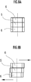
[第6実施形態]
図8を参照して、第6実施形態の円盤状砥石1を説明する。第6実施形態の円盤状砥石1は、移動砥石6が軸方向に分割されていない点を除き、第1実施形態のものと同一に構成される。第6実施形態の円盤状砥石1では、移動砥石6の移動方向を交互に異ならせることにより、幅を変化させている。これによっても、円盤状砥石1を交換することなく迅速に複数種のクランクシャフトS(研削対象物)に対応することができる。また、移動砥石6の移動方向が交互に異なっているため、部分的に研削されない個所も交互にずれることにより、研削効率の低下も抑制することができる。
[Sixth Embodiment]
With reference to FIG. 8, the disk-shaped
[第7実施形態]
図9を参照して、第7実施形態の円盤状砥石1を説明する。なお、第7実施形態の円盤状砥石1において、第1実施形態と同一の構成については同一の符号を付してその構成の説明を省略する。第7実施形態の円盤状砥石1は、第1実施形態の変形例としても説明したように、移動基材7は、その径方向内方側で環状連結部17を介して一体に接続されている。
[Seventh Embodiment]
With reference to FIG. 9, the disk-shaped
図10に示すように、固定砥石5の周方向一方側は、隣接する移動砥石6に接近するほど幅が狭くなるように傾斜する固定側傾斜面18が設けられている。また、移動砥石6の周方向他方側は、固定砥石5の固定側傾斜面18に対応させて傾斜する移動側傾斜面19が設けられている。第7実施形態においては、この固定側傾斜面18と移動側傾斜面19とで本発明のテーパ部が構成されている。
As shown in FIG. 10, one side in the circumferential direction of the fixed
図9に示すように、第7実施形態の円盤状砥石1では、調整ネジに代えてカムピン20を回転させることにより移動砥石6の軸方向への移動量を調整する。図11に示すように、カムピン20は、回転軸20aの中央に位置させて円盤状のカム本体20bが回転軸20aに対して偏心した状態で設けられている。固定砥石5が固定された円盤状基材3には、カム本体20bに対応させてカム孔21が穿設されている。回転軸20aの端面には図示省略した六角レンチが係合可能な六角穴20cが設けられている。
As shown in FIG. 9, in the disc-shaped
図10Aは、円盤状砥石1の幅が最も狭い状態を示している。図10Bは、図10Aの状態からカムピン20を回転させて、固定側傾斜面18と移動側傾斜面19とによって、軸方向に隣接する移動砥石6の間に固定砥石5が入り込むようにして円盤状砥石1の幅が広げられる。
FIG. 10A shows a state where the width of the disc-shaped
また、図9に示すように、円盤状基材3には目盛り22が振ってあり、環状連結部17には、目盛り22に対応させて矢印23が設けられている。これにより、円盤状砥石1の実際の幅を測定することなく、現在の円盤状砥石1の幅を読み取ることができる。また、第7実施形態の円盤状砥石1には、円盤状基材3と移動基材7とを貫通するように挿通された固定ボルト24が設けられている。この固定ボルト24に図示省略したナットを螺合させることで、円盤状基材3と移動基材7とが幅の変更が必要ないときには相対回転できないように締め付けて固定している。
Further, as shown in FIG. 9, a
なお、第7実施形態においては、テーパ部として固定側傾斜面18と移動側傾斜面19とを設けた円盤状砥石1について説明した。しかしながら、本発明のテーパ部はこれに限らず、例えばテーパ部を、固定側傾斜面18と移動側傾斜面19との何れか一方の傾斜面だけ設けて他方は一方の傾斜面に当接する当接部を設けて構成してもよい。
In addition, in 7th Embodiment, the disk shaped
[第8実施形態]
図12に示すように、第8実施形態の円盤状砥石1は、第7実施形態のカムピン20とカム孔21に代えてギヤ25とギヤ25に噛合するラック26を設けた点を除き、第7実施形態のものと同一に構成される。ギヤ25とラック26とによっても、環状連結部17と円盤状基材3とを相対回転させることができ、第7実施形態のものと同様に円盤状砥石1の幅を調整することができる。
[Eighth Embodiment]
As shown in FIG. 12, the disc-shaped
1 円盤状砥石
2 研削装置
3 円盤状基材
4 分割砥石
5 固定砥石
5a 角部
6 移動砥石
6a 角部
6b 軸方向端面
7 移動基材
8 砥石本体
9 突片
9a 貫通孔
9b ネジ孔
9c 係合突部
10 受入穴
11 貫通孔
12 ガイドピン
13 調整ネジ
13a 六角穴
14 受入部
14a 雌ネジ
15 雄ネジ蓋
15a 孔
16 カムネジ
16a カム溝
16b 六角穴
17 環状連結部
18 固定側傾斜面(テーパ部)
19 移動側傾斜面(テーパ部)
20 カムピン
20a 回転軸
20b カム本体
20c 六角穴
21 カム孔
22 目盛り
23 矢印
24 固定ボルト
25 ギヤ
26 ラック
S クランクシャフト(軸物、研削対象物)
DESCRIPTION OF
19 Moving side inclined surface (tapered part)
20
Claims (7)
前記分割砥石の軸方向の角部は、曲面形状に形成され、
前記移動砥石と前記移動砥石以外の他の分割砥石とでは、軸方向の角部の曲率半径が夫々異なり、
前記他の分割砥石の軸方向の両角部の曲率半径は同一であり、
前記移動砥石は軸方向に隣接させて複数設けられており、
前記移動砥石の他の移動砥石に隣接しない軸方向角部同士の曲率半径は同一であることを特徴とする円盤状砥石。 A disc-shaped grindstone configured by providing a plurality of divided grindstones divided in the circumferential direction on the outer peripheral surface of a disc-shaped base material, wherein at least a part of the grindstone is movable in the axial direction of the disc-shaped base material grindstone der is,
The axial corners of the divided grindstone are formed in a curved surface shape,
The mobile grindstone and other division grindstone other than the moving wheels, the radius of curvature of the corner portion in the axial direction varies respectively,
The curvature radii of both corners in the axial direction of the other divided grindstone are the same,
A plurality of the moving grindstones are provided adjacent to each other in the axial direction,
The radius of curvature of the axial angle portions not adjacent to other mobile grindstone moving grindstone disc-shaped grinding wheel, wherein identical der Rukoto.
前記分割砥石のうち前記円盤状基材に軸方向に移動不能に固定された分割砥石を固定砥石として、
前記移動砥石と前記固定砥石とでは、軸方向の角部の曲率半径が夫々異なることを特徴とする円盤状砥石。 The disc-shaped grindstone according to claim 1 ,
Divided grindstone that is immovably secured in the axial direction to the disc-shaped substrate of the previous SL divided grindstone as a fixed grinding wheel,
The disc-shaped grindstone is characterized in that the moving grindstone and the fixed grindstone have different curvature radii at the corners in the axial direction.
前記移動砥石の他の移動砥石に隣接する軸方向端面は、前記円盤状基材の軸方向に対して傾斜する傾斜面であることを特徴とする円盤状砥石。 The disc-shaped grindstone according to claim 1 or 2,
An axial end surface adjacent to another moving grindstone of the moving grindstone is an inclined surface that is inclined with respect to the axial direction of the disc-shaped base material.
前記移動砥石の他の移動砥石に隣接する軸方向端面の位置が周方向に位置する他の移動砥石の軸方向端面の位置に対してずれていることを特徴とする円盤状砥石。 The disc-shaped grindstone according to claim 1 or 2,
A disc-shaped grindstone characterized in that a position of an axial end face adjacent to another moving grindstone of the moving grindstone is deviated from a position of an axial end face of another moving grindstone located in the circumferential direction .
前記移動砥石は、軸方向に2分割された2分割砥石と、軸方向に3分割された3分割砥石とからなることを特徴とする円盤状砥石。 The disc-shaped grindstone according to any one of claims 1 to 4 ,
The moving grindstone is composed of a two-part grindstone divided into two in the axial direction and a three-part grindstone divided into three in the axial direction.
前記移動砥石の軸方向への移動量を調整自在な調整ネジが設けられることを特徴とする円盤状砥石。 The disc-shaped grindstone according to any one of claims 1 to 5,
A disc-shaped grindstone characterized in that an adjustment screw capable of adjusting an amount of movement of the moving grindstone in the axial direction is provided.
前記分割砥石のうち前記円盤状基材に軸方向に移動不能に固定された分割砥石を固定砥石として、
前記固定砥石は板状であり、
前記移動砥石は、板状の前記固定砥石を軸方向から挟み込む一対の可動板で構成され、
前記固定砥石と前記可動板との間には、周方向に向かって徐々に厚さが変化するテーパ部が設けられ、
前記固定砥石と前記可動板とを相対回転させることにより、前記テーパ部によって、一対の前記可動板同士の間の間隔を変化させて、軸方向の幅を変更することを特徴とする円盤状砥石。 The disc-shaped grindstone according to any one of claims 1 to 5,
Among the divided grindstones, the divided grindstone fixed to the disk-like base material so as not to move in the axial direction is used as a fixed grindstone.
The fixed grindstone is plate-shaped,
The moving grindstone is composed of a pair of movable plates that sandwich the plate-shaped fixed grindstone from the axial direction,
Between the fixed grindstone and the movable plate, a tapered portion is provided whose thickness gradually changes in the circumferential direction,
The disk-shaped grindstone is characterized in that by rotating the fixed grindstone and the movable plate relative to each other, the taper portion changes the distance between the pair of movable plates to change the width in the axial direction. .
Priority Applications (2)
| Application Number | Priority Date | Filing Date | Title |
|---|---|---|---|
| JP2014175323A JP6411136B2 (en) | 2014-08-29 | 2014-08-29 | Disc-shaped grinding wheel |
| US14/832,090 US9550275B2 (en) | 2014-08-29 | 2015-08-21 | Disc-shaped grindstone |
Applications Claiming Priority (1)
| Application Number | Priority Date | Filing Date | Title |
|---|---|---|---|
| JP2014175323A JP6411136B2 (en) | 2014-08-29 | 2014-08-29 | Disc-shaped grinding wheel |
Publications (3)
| Publication Number | Publication Date |
|---|---|
| JP2016049582A JP2016049582A (en) | 2016-04-11 |
| JP2016049582A5 JP2016049582A5 (en) | 2017-08-24 |
| JP6411136B2 true JP6411136B2 (en) | 2018-10-24 |
Family
ID=55401434
Family Applications (1)
| Application Number | Title | Priority Date | Filing Date |
|---|---|---|---|
| JP2014175323A Active JP6411136B2 (en) | 2014-08-29 | 2014-08-29 | Disc-shaped grinding wheel |
Country Status (2)
| Country | Link |
|---|---|
| US (1) | US9550275B2 (en) |
| JP (1) | JP6411136B2 (en) |
Families Citing this family (3)
| Publication number | Priority date | Publication date | Assignee | Title |
|---|---|---|---|---|
| JP6411136B2 (en) * | 2014-08-29 | 2018-10-24 | 本田技研工業株式会社 | Disc-shaped grinding wheel |
| CN114346884B (en) * | 2022-03-17 | 2022-05-27 | 徐州瑞达装备制造有限公司 | High strength fastener manufacturing is with burnishing and polishing device |
| CN114734381A (en) * | 2022-03-29 | 2022-07-12 | 哈尔滨工业大学 | Split type CVD diamond grinding tool and manufacturing method thereof |
Family Cites Families (18)
| Publication number | Priority date | Publication date | Assignee | Title |
|---|---|---|---|---|
| US3324607A (en) * | 1964-08-13 | 1967-06-13 | Super Cut | Rotary grinding tool with interrupted abrasive helicoid |
| US3376673A (en) * | 1964-09-08 | 1968-04-09 | Super Cut | Rotary cutter assembly for concrete leveler |
| US3951619A (en) * | 1973-05-11 | 1976-04-20 | Frangipane Joseph G | Method of making a grinding wheel |
| JPS57194824A (en) * | 1981-05-21 | 1982-11-30 | Nikko Kikai Kk | Disk for grinding |
| DE3824543A1 (en) * | 1988-07-20 | 1990-01-25 | Naxos Union Schleifmittel | GRINDING WHEEL |
| DE4012624C1 (en) * | 1990-04-20 | 1991-10-02 | Michael Dipl.-Phys. Dipl.-Ing. 4600 Dortmund De Kalm | Segmental grinding wheel - has grinding segments carried on free ends of swivel levers |
| US5707278A (en) * | 1994-05-05 | 1998-01-13 | Sunnen Products Company | Honing tool and method for manufacturing same |
| US5725416A (en) * | 1995-12-20 | 1998-03-10 | Russell; Jerry | Apparatus and method for making and using a combined cutting/grinding wheel |
| JP3614636B2 (en) * | 1998-01-29 | 2005-01-26 | 本田技研工業株式会社 | Crankshaft clamping device and crankshaft grinding method |
| EP0989924B1 (en) * | 1998-04-21 | 2002-12-18 | Tyrolit Schleifmittelwerke Swarovski KG | Grinding wheel |
| KR100440871B1 (en) * | 2001-02-19 | 2004-07-19 | 이화다이아몬드공업 주식회사 | core drill |
| JP2003048165A (en) * | 2001-08-06 | 2003-02-18 | Noritake Super Abrasive:Kk | Rotary disc type machining tool |
| DE50309740D1 (en) * | 2003-11-12 | 2008-06-12 | Erwin Junker Grinding Technolo | Shared grinding tool |
| JP4874121B2 (en) * | 2004-11-19 | 2012-02-15 | 豊田バンモップス株式会社 | Grinding wheel |
| JP5034427B2 (en) * | 2006-10-12 | 2012-09-26 | 株式会社ジェイテクト | Method for releasing dynamic pressure of grinding fluid in grinding, grinding method using the method, and grinding wheel used in the grinding method |
| JP5115352B2 (en) * | 2008-06-20 | 2013-01-09 | 株式会社ジェイテクト | Grinding equipment and cutting equipment |
| US9050706B2 (en) * | 2012-02-22 | 2015-06-09 | Inland Diamond Products Company | Segmented profiled wheel and method for making same |
| JP6411136B2 (en) * | 2014-08-29 | 2018-10-24 | 本田技研工業株式会社 | Disc-shaped grinding wheel |
-
2014
- 2014-08-29 JP JP2014175323A patent/JP6411136B2/en active Active
-
2015
- 2015-08-21 US US14/832,090 patent/US9550275B2/en active Active
Also Published As
| Publication number | Publication date |
|---|---|
| JP2016049582A (en) | 2016-04-11 |
| US9550275B2 (en) | 2017-01-24 |
| US20160059387A1 (en) | 2016-03-03 |
Similar Documents
| Publication | Publication Date | Title |
|---|---|---|
| JP6411136B2 (en) | Disc-shaped grinding wheel | |
| TWI638703B (en) | Rotary table device | |
| JP2013039664A (en) | Simultaneous grinding machine | |
| CN101823192B (en) | Barreling tool for processing excircles, R surfaces and end faces | |
| EP2561959B1 (en) | Drive assembly for a grinder | |
| TWI693353B (en) | Slewing bearing | |
| CN109500705A (en) | A kind of metal bar end face grinding device | |
| JP7446733B2 (en) | Barrel and wheel equipped with the barrel | |
| EP1900478B1 (en) | Super finishing stone and super finishing method | |
| JP2016049582A5 (en) | ||
| WO2016081167A1 (en) | Support pin for spring guidance in a camshaft phaser | |
| KR102336169B1 (en) | Equipment and grinding machine for the grinding of external rings of roller bearings | |
| JP5873531B2 (en) | Timepiece movement | |
| CN103921204B (en) | Based on horizontal ball grinding machine steel ball grinding without skidding regulate and control method | |
| JP2007301700A (en) | Grinding wheel having multilayer structure | |
| WO2014010629A1 (en) | Tripod-type constant-velocity joint and method for manufacturing same | |
| JP5169476B2 (en) | Grinding method of track groove of tripod type constant velocity universal joint | |
| WO2017014001A1 (en) | Superfinishing method for roller bearing rolling surface | |
| CN108747495A (en) | Flange clamp | |
| JP5501145B2 (en) | Ball spline and its inner shaft spline track machining method | |
| JP5672733B2 (en) | Power transmission chain pin grinding apparatus and grinding method | |
| TWI716538B (en) | Combined cylindrical roller bearing | |
| JP6886105B2 (en) | Blade fixing device and dicing device | |
| JP5777587B2 (en) | Dresser for thread grinding wheel | |
| JPH056063Y2 (en) |
Legal Events
| Date | Code | Title | Description |
|---|---|---|---|
| A521 | Written amendment |
Free format text: JAPANESE INTERMEDIATE CODE: A523 Effective date: 20170710 |
|
| A621 | Written request for application examination |
Free format text: JAPANESE INTERMEDIATE CODE: A621 Effective date: 20170710 |
|
| A977 | Report on retrieval |
Free format text: JAPANESE INTERMEDIATE CODE: A971007 Effective date: 20180417 |
|
| A131 | Notification of reasons for refusal |
Free format text: JAPANESE INTERMEDIATE CODE: A131 Effective date: 20180522 |
|
| A521 | Written amendment |
Free format text: JAPANESE INTERMEDIATE CODE: A523 Effective date: 20180719 |
|
| TRDD | Decision of grant or rejection written | ||
| A01 | Written decision to grant a patent or to grant a registration (utility model) |
Free format text: JAPANESE INTERMEDIATE CODE: A01 Effective date: 20180904 |
|
| A61 | First payment of annual fees (during grant procedure) |
Free format text: JAPANESE INTERMEDIATE CODE: A61 Effective date: 20180926 |
|
| R150 | Certificate of patent or registration of utility model |
Ref document number: 6411136 Country of ref document: JP Free format text: JAPANESE INTERMEDIATE CODE: R150 |