JP6408158B2 - Femoral stem and post stem for hip prosthesis - Google Patents
Femoral stem and post stem for hip prosthesis Download PDFInfo
- Publication number
- JP6408158B2 JP6408158B2 JP2017533165A JP2017533165A JP6408158B2 JP 6408158 B2 JP6408158 B2 JP 6408158B2 JP 2017533165 A JP2017533165 A JP 2017533165A JP 2017533165 A JP2017533165 A JP 2017533165A JP 6408158 B2 JP6408158 B2 JP 6408158B2
- Authority
- JP
- Japan
- Prior art keywords
- femoral
- femur
- femoral stem
- lateral
- port
- Prior art date
- Legal status (The legal status is an assumption and is not a legal conclusion. Google has not performed a legal analysis and makes no representation as to the accuracy of the status listed.)
- Active
Links
Images


Classifications
-
- A—HUMAN NECESSITIES
- A61—MEDICAL OR VETERINARY SCIENCE; HYGIENE
- A61F—FILTERS IMPLANTABLE INTO BLOOD VESSELS; PROSTHESES; DEVICES PROVIDING PATENCY TO, OR PREVENTING COLLAPSING OF, TUBULAR STRUCTURES OF THE BODY, e.g. STENTS; ORTHOPAEDIC, NURSING OR CONTRACEPTIVE DEVICES; FOMENTATION; TREATMENT OR PROTECTION OF EYES OR EARS; BANDAGES, DRESSINGS OR ABSORBENT PADS; FIRST-AID KITS
- A61F2/00—Filters implantable into blood vessels; Prostheses, i.e. artificial substitutes or replacements for parts of the body; Appliances for connecting them with the body; Devices providing patency to, or preventing collapsing of, tubular structures of the body, e.g. stents
- A61F2/02—Prostheses implantable into the body
- A61F2/30—Joints
- A61F2/32—Joints for the hip
- A61F2/36—Femoral heads ; Femoral endoprostheses
- A61F2/3662—Femoral shafts
-
- A—HUMAN NECESSITIES
- A61—MEDICAL OR VETERINARY SCIENCE; HYGIENE
- A61B—DIAGNOSIS; SURGERY; IDENTIFICATION
- A61B17/00—Surgical instruments, devices or methods, e.g. tourniquets
- A61B17/16—Bone cutting, breaking or removal means other than saws, e.g. Osteoclasts; Drills or chisels for bones; Trepans
- A61B17/1662—Bone cutting, breaking or removal means other than saws, e.g. Osteoclasts; Drills or chisels for bones; Trepans for particular parts of the body
- A61B17/1664—Bone cutting, breaking or removal means other than saws, e.g. Osteoclasts; Drills or chisels for bones; Trepans for particular parts of the body for the hip
- A61B17/1668—Bone cutting, breaking or removal means other than saws, e.g. Osteoclasts; Drills or chisels for bones; Trepans for particular parts of the body for the hip for the upper femur
-
- A—HUMAN NECESSITIES
- A61—MEDICAL OR VETERINARY SCIENCE; HYGIENE
- A61F—FILTERS IMPLANTABLE INTO BLOOD VESSELS; PROSTHESES; DEVICES PROVIDING PATENCY TO, OR PREVENTING COLLAPSING OF, TUBULAR STRUCTURES OF THE BODY, e.g. STENTS; ORTHOPAEDIC, NURSING OR CONTRACEPTIVE DEVICES; FOMENTATION; TREATMENT OR PROTECTION OF EYES OR EARS; BANDAGES, DRESSINGS OR ABSORBENT PADS; FIRST-AID KITS
- A61F2/00—Filters implantable into blood vessels; Prostheses, i.e. artificial substitutes or replacements for parts of the body; Appliances for connecting them with the body; Devices providing patency to, or preventing collapsing of, tubular structures of the body, e.g. stents
- A61F2/02—Prostheses implantable into the body
- A61F2/30—Joints
- A61F2/32—Joints for the hip
- A61F2/36—Femoral heads ; Femoral endoprostheses
- A61F2/3662—Femoral shafts
- A61F2/367—Proximal or metaphyseal parts of shafts
-
- A—HUMAN NECESSITIES
- A61—MEDICAL OR VETERINARY SCIENCE; HYGIENE
- A61F—FILTERS IMPLANTABLE INTO BLOOD VESSELS; PROSTHESES; DEVICES PROVIDING PATENCY TO, OR PREVENTING COLLAPSING OF, TUBULAR STRUCTURES OF THE BODY, e.g. STENTS; ORTHOPAEDIC, NURSING OR CONTRACEPTIVE DEVICES; FOMENTATION; TREATMENT OR PROTECTION OF EYES OR EARS; BANDAGES, DRESSINGS OR ABSORBENT PADS; FIRST-AID KITS
- A61F2/00—Filters implantable into blood vessels; Prostheses, i.e. artificial substitutes or replacements for parts of the body; Appliances for connecting them with the body; Devices providing patency to, or preventing collapsing of, tubular structures of the body, e.g. stents
- A61F2/02—Prostheses implantable into the body
- A61F2/30—Joints
- A61F2002/30001—Additional features of subject-matter classified in A61F2/28, A61F2/30 and subgroups thereof
- A61F2002/30316—The prosthesis having different structural features at different locations within the same prosthesis; Connections between prosthetic parts; Special structural features of bone or joint prostheses not otherwise provided for
- A61F2002/30329—Connections or couplings between prosthetic parts, e.g. between modular parts; Connecting elements
- A61F2002/30405—Connections or couplings between prosthetic parts, e.g. between modular parts; Connecting elements made by screwing complementary threads machined on the parts themselves
-
- A—HUMAN NECESSITIES
- A61—MEDICAL OR VETERINARY SCIENCE; HYGIENE
- A61F—FILTERS IMPLANTABLE INTO BLOOD VESSELS; PROSTHESES; DEVICES PROVIDING PATENCY TO, OR PREVENTING COLLAPSING OF, TUBULAR STRUCTURES OF THE BODY, e.g. STENTS; ORTHOPAEDIC, NURSING OR CONTRACEPTIVE DEVICES; FOMENTATION; TREATMENT OR PROTECTION OF EYES OR EARS; BANDAGES, DRESSINGS OR ABSORBENT PADS; FIRST-AID KITS
- A61F2/00—Filters implantable into blood vessels; Prostheses, i.e. artificial substitutes or replacements for parts of the body; Appliances for connecting them with the body; Devices providing patency to, or preventing collapsing of, tubular structures of the body, e.g. stents
- A61F2/02—Prostheses implantable into the body
- A61F2/30—Joints
- A61F2/30767—Special external or bone-contacting surface, e.g. coating for improving bone ingrowth
- A61F2/30771—Special external or bone-contacting surface, e.g. coating for improving bone ingrowth applied in original prostheses, e.g. holes or grooves
- A61F2002/30772—Apertures or holes, e.g. of circular cross section
- A61F2002/30774—Apertures or holes, e.g. of circular cross section internally-threaded
-
- A—HUMAN NECESSITIES
- A61—MEDICAL OR VETERINARY SCIENCE; HYGIENE
- A61F—FILTERS IMPLANTABLE INTO BLOOD VESSELS; PROSTHESES; DEVICES PROVIDING PATENCY TO, OR PREVENTING COLLAPSING OF, TUBULAR STRUCTURES OF THE BODY, e.g. STENTS; ORTHOPAEDIC, NURSING OR CONTRACEPTIVE DEVICES; FOMENTATION; TREATMENT OR PROTECTION OF EYES OR EARS; BANDAGES, DRESSINGS OR ABSORBENT PADS; FIRST-AID KITS
- A61F2/00—Filters implantable into blood vessels; Prostheses, i.e. artificial substitutes or replacements for parts of the body; Appliances for connecting them with the body; Devices providing patency to, or preventing collapsing of, tubular structures of the body, e.g. stents
- A61F2/02—Prostheses implantable into the body
- A61F2/30—Joints
- A61F2/30767—Special external or bone-contacting surface, e.g. coating for improving bone ingrowth
- A61F2/30771—Special external or bone-contacting surface, e.g. coating for improving bone ingrowth applied in original prostheses, e.g. holes or grooves
- A61F2002/30878—Special external or bone-contacting surface, e.g. coating for improving bone ingrowth applied in original prostheses, e.g. holes or grooves with non-sharp protrusions, for instance contacting the bone for anchoring, e.g. keels, pegs, pins, posts, shanks, stems, struts
-
- A—HUMAN NECESSITIES
- A61—MEDICAL OR VETERINARY SCIENCE; HYGIENE
- A61F—FILTERS IMPLANTABLE INTO BLOOD VESSELS; PROSTHESES; DEVICES PROVIDING PATENCY TO, OR PREVENTING COLLAPSING OF, TUBULAR STRUCTURES OF THE BODY, e.g. STENTS; ORTHOPAEDIC, NURSING OR CONTRACEPTIVE DEVICES; FOMENTATION; TREATMENT OR PROTECTION OF EYES OR EARS; BANDAGES, DRESSINGS OR ABSORBENT PADS; FIRST-AID KITS
- A61F2/00—Filters implantable into blood vessels; Prostheses, i.e. artificial substitutes or replacements for parts of the body; Appliances for connecting them with the body; Devices providing patency to, or preventing collapsing of, tubular structures of the body, e.g. stents
- A61F2/02—Prostheses implantable into the body
- A61F2/30—Joints
- A61F2/32—Joints for the hip
- A61F2/36—Femoral heads ; Femoral endoprostheses
- A61F2/3609—Femoral heads or necks; Connections of endoprosthetic heads or necks to endoprosthetic femoral shafts
- A61F2002/3625—Necks
- A61F2002/3647—Necks pierced with a longitudinal bore
-
- A—HUMAN NECESSITIES
- A61—MEDICAL OR VETERINARY SCIENCE; HYGIENE
- A61F—FILTERS IMPLANTABLE INTO BLOOD VESSELS; PROSTHESES; DEVICES PROVIDING PATENCY TO, OR PREVENTING COLLAPSING OF, TUBULAR STRUCTURES OF THE BODY, e.g. STENTS; ORTHOPAEDIC, NURSING OR CONTRACEPTIVE DEVICES; FOMENTATION; TREATMENT OR PROTECTION OF EYES OR EARS; BANDAGES, DRESSINGS OR ABSORBENT PADS; FIRST-AID KITS
- A61F2/00—Filters implantable into blood vessels; Prostheses, i.e. artificial substitutes or replacements for parts of the body; Appliances for connecting them with the body; Devices providing patency to, or preventing collapsing of, tubular structures of the body, e.g. stents
- A61F2/02—Prostheses implantable into the body
- A61F2/30—Joints
- A61F2/32—Joints for the hip
- A61F2/36—Femoral heads ; Femoral endoprostheses
- A61F2/3662—Femoral shafts
- A61F2002/3678—Geometrical features
- A61F2002/368—Geometrical features with lateral apertures, bores, holes or openings, e.g. for reducing the mass, for receiving fixation screws or for communicating with the inside of a hollow shaft
Description
本発明は、股関節の生まれつきの関節部を人工器具で置き換えるために用いられる人工股関節のための大腿骨ステムに関する。特に、本発明は、陥没を阻止する改造型大腿骨ステムに関する。 The present invention relates to a femoral stem for an artificial hip joint that is used to replace the natural joint of the hip joint with a prosthetic device. In particular, the present invention relates to a modified femoral stem that prevents depression.
整形外科分野において、股関節の手術は、一般に、病理学的病態、例えば関節症、関節炎、股関節脱臼、大腿骨頭部及び頸部骨折、又は股関節の進行性摩耗、疼痛、又は機能障害を発生させる類似の病態を治療するために実施されることが周知である。股関節は、大腿骨を寛骨に連結し、この股関節は、寛骨臼内に嵌り込んだ大腿骨頭部を含み、寛骨臼は、寛骨の外側フェースに設けられた関節腔である。大腿骨中には、上述の大腿骨頭部に加えて、大腿骨頭部を大腿骨本体に連結する頸部が存在し、この頸部は、かなり長手方向の展開を呈する。 In the orthopedic field, hip surgery generally results in pathological conditions such as arthropathy, arthritis, hip dislocation, femoral head and neck fractures, or similar hips that cause progressive wear, pain, or dysfunction It is well known that it is carried out to treat the pathological conditions. The hip joint connects the femur to the hipbone, the hip joint includes a femoral head that fits within the acetabulum, and the acetabulum is a joint cavity provided in the outer face of the acetabulum. In the femur, in addition to the above-described femoral head, there is a neck that connects the femoral head to the femoral body, and this neck exhibits a substantial longitudinal deployment.
したがって、股関節部の生まれつきの形状に基づいて、植え込まれるべき人工股関節は、大腿骨部及び寛骨部を含む。大腿骨ステムと呼ばれる大腿骨の部分は、典型的には、外科用金属、即ち、チタン合金又はステンレス鋼で作られ、寛骨臼カップと呼ばれる骨盤の部分は、典型的には、超高分子量ポリエチレン(UHMWP)及び/又は外科用金属、即ち、チタン合金又はステンレス鋼で作られる。大腿骨ステムは、ステムとも呼ばれている本体を有し、この本体は、生まれつきの大腿骨体に設けられた骨の長手方向腔中に植え込まれる。寛骨臼カップは、生まれつきの寛骨臼に設けられた骨床中に植え込まれる。かかる大腿骨ステムは、肩部を備えた生まれつきの大腿骨体の頂部で終端しており、肩部は、この肩部から突き出るとともに終末円錐を備えた大腿骨頸部中に合体している。これ又金属又はセラミックスで作られた球状大腿骨頭部が上述の終末円錐に嵌められ、この球状大腿骨頭部は、これが寛骨臼カップ中に配置された後に人工球状(ボール状・ソケット状)関節のピボットボールを形成する。 Therefore, based on the natural shape of the hip joint, the artificial hip joint to be implanted includes the femur and the hipbone. The portion of the femur called the femoral stem is typically made of surgical metal, i.e. titanium alloy or stainless steel, and the portion of the pelvis called the acetabular cup is typically ultra-high molecular weight Made of polyethylene (UHMWP) and / or surgical metal, ie titanium alloy or stainless steel. The femoral stem has a body, also called a stem, that is implanted in the longitudinal cavity of the bone provided in the native femoral body. The acetabular cup is implanted in the bone bed provided in the natural acetabulum. Such a femoral stem terminates at the apex of a native femoral body with a shoulder, which projects from the shoulder and merges into a femoral neck with an end cone. A spherical femoral head also made of metal or ceramics is fitted into the terminal cone described above, and this spherical femoral head is placed in an acetabular cup and then an artificial spherical (ball-shaped / socket-shaped) joint. Form a pivot ball.
患者の股関節部に対する外科的手技又は手術は、大腿骨頭部及び頸部を除去するための大腿骨頸部の切断で始まる。かかる手技は、大腿骨頸部切除又は骨切り術と呼ばれている。切除した生まれつきの大腿骨頭部及び頸部は、大腿管の頂部を露出させるよう除去する。適正なピン、ドリル、及びやすりによる大腿骨の次の前処理において人工ステムが挿入される大腿骨の内部管を前処理する。次に、球形ミルを用いて軟骨を含む骨を除去して、次に寛骨臼カップが挿入される座部を形成することによって寛骨臼を前処理する。次に、寛骨臼ステムを前処理した大腿管中に挿入する。球状頭部を人工大腿骨頸部の終末円錐に嵌める。大腿骨ステムと頭部を互いに組み立てた後、頭部を植え込み状態の寛骨臼カップ中に入れて整復し、それにより股関節の元の形態を回復させる。 A surgical procedure or operation on the patient's hip begins with the femoral neck cut to remove the femoral head and neck. Such a procedure is called femoral neck resection or osteotomy. The resected native femoral head and neck are removed to expose the top of the femoral canal. Pre-process the femoral internal tube into which the prosthetic stem is inserted in the next pre-processing of the femur with appropriate pins, drills and files. The acetabulum is then pretreated by removing the bone containing cartilage using a spherical mill and then forming a seat into which the acetabular cup is inserted. The acetabular stem is then inserted into the pretreated femoral canal. Fit the spherical head into the terminal cone of the artificial femoral neck. After the femoral stem and head are assembled together, the head is placed in an implanted acetabular cup and reduced, thereby restoring the original shape of the hip joint.
いったん植え込まれると、人工大腿骨及び寛骨臼カップは、股関節の原形状及び機能をほぼ同一に再生する。こうすることによって、疼痛の鎮痛と股関節部の機能の回復が得られ、それにより患者は、長年にわたって通常の生活を送ることができる。 Once implanted, the prosthetic femur and acetabular cup recreate the hip shape and function approximately identically. This provides pain relief and restoration of hip function, allowing the patient to live a normal life for many years.
ステムは、3つの主要な方法により大腿骨内に固着される。第1の方法では、液体ポリマーをステムの周りに凝固させかかる凝固状態の液体ポリマーは、セメントとして働き、ステム骨にしっかりと結合する。最新式の方法では、自然なプロセスを用い、それにより、大腿骨ステムを大腿管の骨床中に圧力嵌めし又は押し込む。骨とステムの直接的な接触により、ステムの金属中への骨の一体化が可能になる。金属インプラント中への骨成長の固着能力は、金属の粗い又は模様付きの外面によって促進される。ステム固定の最終的で最後のしかも普及してはいない方法は、ステムを大腿管の壁に固着させる数本のスクリュを用いる。 The stem is secured in the femur by three main methods. In the first method, the liquid polymer is allowed to solidify around the stem, such solidified liquid polymer acts as a cement and binds firmly to the stem bone. State-of-the-art methods use a natural process whereby the femoral stem is press fit or pushed into the femoral canal bed. The direct contact between the bone and the stem allows the integration of the bone into the metal of the stem. The ability of bone growth to anchor into a metal implant is facilitated by a rough or textured outer surface of the metal. The final, last and less popular method of stem fixation uses several screws that secure the stem to the femoral canal wall.
圧力嵌め式骨内方成長方法の大きな一欠点は、陥没(subsidence)である。陥没は、大腿骨体の骨管に沿ってこれを下る植え込み状態の大腿骨ステムの術後漸次運動又は移動である。ある特定の患者、特に活動を最小限にするための指図を理解することができない活動的な患者又は動物では、大腿骨ステムを骨の一体化に先立って、通常の又は正常な活動からの衝撃の繰り返しにより大腿骨中にさらに押し込まれる場合がある。陥没の結果として、1)骨が金属表面中に成長する能力が低下し、その結果大腿骨ステムが弛むこと、2)ステムの位置が著しく変化し、その結果カップからの大腿骨頭部の脱臼の発生が増大すること、及び3)インプラントが管に沿って下に押される状態になるので大腿骨体の骨折が生じる場合がある。特に人間ではない患者、例えば犬又は猫の大腿骨の骨折又は破断は、人間と比較して骨の皮質壁が薄いことに起因している場合がある。 One major drawback of the press-fit bone ingrowth method is subsidence. A depression is a post-operative gradual movement or movement of the implanted femoral stem down the bone canal of the femoral body. In certain patients, especially those who are unable to understand instructions to minimize activity, the impact from normal or normal activity prior to bone integration of the femoral stem May be pushed further into the femur. As a result of the depression, 1) the ability of the bone to grow into the metal surface is reduced, resulting in the femoral stem becoming loose, and 2) the position of the stem changes significantly, resulting in dislocation of the femoral head from the cup. The occurrence is increased and 3) femoral fractures may occur as the implant is pushed down along the canal. In particular, fractures or fractures in the femur of non-human patients, such as dogs or cats, may be due to the thin cortical walls of the bone compared to humans.
本発明は、これらの要望に応えて他の関連の利点を提供することにある。 The present invention provides other related advantages in response to these needs.
本発明は、人工股関節用の大腿骨ステムに関する。大腿骨ステムは、近位端部及び遠位端部を備えた全体として細長い形状を有する大腿骨底を有する。大腿骨ステムは、大腿骨底の近位端部から延びるとともに同心軸線を備えた全体として管状の形状を有する大腿骨頸部をさらに有する。側方ポートが大腿骨頸部と全体として反対側に位置する大腿骨底の側部に同心軸線と整列した状態で設けられている。大腿骨ステムは、側方ポート内に取り外し可能に固定された第1の端部及び大腿骨底の側部から所定の距離にわたって延びる第2の端部を備えた側方ポストをさらに有する。 The present invention relates to a femoral stem for an artificial hip joint. The femoral stem has a femoral base having a generally elongated shape with a proximal end and a distal end. The femoral stem further includes a femoral neck having a generally tubular shape extending from the proximal end of the femoral base and having a concentric axis. A lateral port is provided in a state of being aligned with the concentric axis on the side of the femoral base located on the opposite side of the femoral neck as a whole. The femoral stem further includes a side post with a first end removably secured within the side port and a second end extending a predetermined distance from the side of the femoral base.
大腿骨底は、好ましくは、細長い形状に沿って長手方向軸線を有し、長手方向軸線と同心軸線は、互いに動作角度をなしている。動作角度は、30°〜60°であるのが良く、動作角度は、好ましくは約45°である。 The femoral base preferably has a longitudinal axis along an elongated shape, the longitudinal axis and the concentric axis being at an operating angle relative to each other. The operating angle may be between 30 ° and 60 °, and the operating angle is preferably about 45 °.
大腿骨ステムは、好ましくは、中心軸線に沿って大腿骨頸部を同心状に貫通して延びる案内穴をさらに有する。案内穴は、好ましくは側方ポートに結合している。側方ポートは、好ましくは、側方ポストの長軸と整列した状態で側方ポストの第1の端部から延びる案内ロッドを有する。案内ロッドは、好ましくは、案内穴の内径に実質的に等しい外径を有し、従って、案内ロッドは、案内穴を通ってぴったりと、しかしながら容易に摺動するようになっている。 The femoral stem preferably further includes a guide hole extending concentrically through the femoral neck along the central axis. The guide hole is preferably connected to the side port. The side port preferably has a guide rod extending from the first end of the side post in alignment with the long axis of the side post. The guide rod preferably has an outer diameter substantially equal to the inner diameter of the guide hole, so that the guide rod is adapted to slide snugly but easily through the guide hole.
大腿骨底の側部からの所定の距離は、側方ポストが側方ポート内に固定されると、側方ポストの第2の端部が、大腿骨ステムが植え込まれる大腿骨の外側皮質を越えて約2mmにわたって延びるようなものである。 The predetermined distance from the side of the femoral base is that when the side post is secured in the side port, the second end of the side post is the outer cortex of the femur where the femoral stem is implanted. And extends over about 2 mm.
上述した側方ステムを植え込む方法は、大腿骨ステムの植え込みのために大腿骨の端部を前処理するステップで始まる。大腿骨ステムは、好ましくは、患者の大腿骨の頸部のレプリカとなる大腿骨頸部を有し、大腿骨ステムは、同心軸線と一線をなして大腿骨頸部と全体として反対側に位置する大腿骨底の側部に設けられた側方ポートを有する。次に、大腿骨ステムを前処理された大腿骨内に植え込む。大腿骨ステムの側方ポートに隣接して大腿骨の外側皮質を貫通して側方穴をあける。次に、側方穴を通って側方ポート中に側方ポストを設置して側方ポストの一部分が大腿骨の外側皮質から突き出るようにする。 The method of implanting a lateral stem described above begins with pre-treating the end of the femur for implantation of the femoral stem. The femoral stem preferably has a femoral neck that is a replica of the neck of the patient's femur, and the femoral stem is positioned generally opposite the femoral neck in line with the concentric axis. A side port provided on the side of the bottom of the femur. The femoral stem is then implanted into the pretreated femur. A lateral hole is drilled through the lateral cortex of the femur adjacent to the lateral port of the femoral stem. A lateral post is then placed through the lateral hole and into the lateral port so that a portion of the lateral post protrudes from the lateral cortex of the femur.
この方法では、前処理ステップは、股関節部球窩に連結された大腿骨を含む患者の股関節を露出させるステップを含むのが良い。大腿骨を股関節部球窩から分離し、大腿骨の頭部及び頸部を切り取って大腿骨の内部を露出させる。大腿骨の露出内部をラスピングして大腿骨ステムを受け入れる腔を作る。 In this method, the pre-processing step may include exposing a patient's hip joint including a femur coupled to the hip joint. The femur is separated from the hip joint, and the head and neck of the femur are cut away to expose the interior of the femur. The exposed interior of the femur is rasped to create a cavity for receiving the femoral stem.
穴あけステップは、第1のドリルビットを案内穴から大腿骨頸部の同心軸線に沿って挿入するとともに側方ポートから挿入して側方ポートに隣接したところで大腿骨に接触させるステップを含むのが良い。第1のドリルビットを用いて大腿骨の外側皮質を貫通してパイロット穴をあけ、パイロット穴を側方ポート及び同心軸線と整列させる。案内ワイヤを案内穴、側方ポート、及び外側皮質のパイロット穴から挿入して案内ワイヤが大腿骨から突き出るようにする。第2のドリルビットをパイロット穴から突き出た案内ワイヤと整列させる。第2のドリルビットを用いて大腿骨頸部の同心軸線と一線をなして外側皮質を貫通して側方穴をあける。第1のドリルビットは、好ましくは、約1.5mmオーダのパイロット穴ドリルビットである。第2のドリルビットは、好ましくは、案内ワイヤに嵌まる套管状ドリルビットである。本方法は、穴あけステップ後に側方ポート及び側方穴をクリーニングして骨屑を除去するステップをさらに含むのが良い。 The drilling step includes inserting a first drill bit from the guide hole along the concentric axis of the femoral neck and from the side port to contact the femur at a location adjacent to the side port. good. A first drill bit is used to drill a pilot hole through the outer cortex of the femur and align the pilot hole with the lateral port and the concentric axis. A guide wire is inserted through the guide hole, lateral port, and pilot hole in the outer cortex so that the guide wire protrudes from the femur. The second drill bit is aligned with the guide wire protruding from the pilot hole. A second drill bit is used to drill a lateral hole through the lateral cortex, aligned with the concentric axis of the femoral neck. The first drill bit is preferably a pilot hole drill bit on the order of about 1.5 mm. The second drill bit is preferably a cannulated drill bit that fits over a guide wire. The method may further include the step of cleaning the lateral ports and lateral holes to remove bone debris after the drilling step.
例えば、ねじ山又は同等の固定機構体によって側方ポストを好ましくは側方ポート内に固定する。植え込みステップは、大腿骨ステムを大腿骨の前処理端部に設けられた腔中に挿入するステップと、大腿骨ステムを腔内に押し込むステップとを含むのが良い。 For example, the side post is preferably secured within the side port by a thread or equivalent securing mechanism. The implanting step may include inserting the femoral stem into a cavity provided at the pre-processed end of the femur and pushing the femoral stem into the cavity.
本方法は、側方穴の深さを測定するステップと、側方穴の測定深さに基づいて側方ポストを選択して側方ポストが少なくとも2mmだけ外側皮質から突き出るようにするステップとをさらに含むのが良い。 The method includes the steps of measuring the depth of the side hole and selecting the side post based on the measured depth of the side hole so that the side post protrudes from the outer cortex by at least 2 mm. Furthermore, it is good to include.
本発明の他の特徴及び他の利点は、添付の図面と関連して行われる以下の詳細な説明から明らかになろう。なお、添付の図面は、本発明の原理を例示として示している。 Other features and other advantages of the present invention will become apparent from the following detailed description, taken in conjunction with the accompanying drawings. The accompanying drawings illustrate the principle of the present invention by way of example.
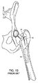
図1A及び図1Bは、イヌ内に人工股関節の一部として植え込まれた先行技術の大腿骨ステム10を示している。図1Aは、大腿骨12内にその通常のかつ意図した深さのところに植え込まれた大腿骨ステム10を示している。図1Bは、陥没後における、即ち、大腿骨ステム10が大腿骨12中に深く動いた後における大腿骨ステム10を示している。陥没の結果として、大腿骨12の割れ又は破断部14が生じている。かかる破断部14は、これらがヒトの大腿骨よりも薄くかつもろい傾向があるので、イヌの骨ではしばしば見受けられる。
1A and 1B show a prior art femoral stem 10 implanted in a dog as part of a hip prosthesis. FIG. 1A shows a
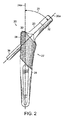
添付の図2〜図8では、イヌ、ヒトへの使用に利用でき、又は他の医療用途に使用できる本発明の側方ポストシステムを備えた大腿骨ステムが全体として参照符号20で示されている。大腿骨ステム22は、ほぼ任意の他の先行技術のステムとほぼ同じ仕方で構成できる。ステム22は、好ましくは、底部分24、頸部26、及び骨の内方成長を可能にする粗面28を有する。底部24は、長手方向軸線24aを有する。頸部26も又、長手方向軸線26aを有している。好ましくは、底部24及び頸部26は、底部長手方向軸線24aと頸部長手方向軸線26aが大腿骨体の垂直軸線に対する大腿骨頸部及び頭部の原角度を再現するオフセット角度25をなすように構成されており、原角度は、種ごとに様々である。イヌの場合、このオフセット角度25は、患者の大腿骨の元の向きに応じて、20°から50°まで様々である。ヒトの場合、このオフセット角度25は、患者の大腿骨の元の向きに応じて、30°から60°まで様々である。他のオフセット角度は、動物の他の種に特有であると言える。頸部26は、好ましくは、植え込み中、球状頭部34を受け入れる先端部32を有し、これについても以下に説明する。
In the attached FIGS. 2-8, a femoral stem with a lateral post system of the present invention that is available for use in dogs, humans or for other medical applications is indicated generally by the
側方ポスト36は、全体として円筒形の構造を有し、この側方ポストは、頸部26と反対側のステム22の側部から突き出ている。以下に説明するように、ポスト36は、所望の支持作用を提供する外側皮質ポストである。側方ポスト36は、頸部26の長手方向軸線26aと整列状態に配置されている。側方ポスト36の露出端部は、好ましくは、ポスト36の操作を可能にし、即ち、回転又は旋回を可能にする球窩38又はこれに類似した構造を有する。球窩38は、六角レンチ又はこれに類似したツールを受け入れるよう構成されているのがよい。以下にさらに説明するように、これは、ねじ山連結によるポスト36の挿入及び取り外しに有用である。
The side post 36 has a generally cylindrical structure, and the side post protrudes from the side of the
図4〜図6は、ステム22へのポスト36の連結部を示している。ポスト36は、球窩38とは反対側に、ポスト36の全体として円筒形の本体が僅かにテーパしている挿入先端部40を有している。連結構造体42、即ちねじ山付き先端部がテーパ付き挿入先端部40の端部に設けられている。ステム22は、ポスト36の挿入先端部40を受け入れるよう構成されたポート44を有している。ポート44は、好ましくは、挿入先端部40のテーパ部にマッチした僅かなテーパ45を有している。ポート44の最も深い端部は、つがい関係をなす連結構造体46、即ち、ねじ山付き穴を有する。ステム22は、頸部26の中心を通ってポート44を出る案内穴48をさらに有している。この案内穴48は、以下に説明する植え込み手技で有用である。
4 to 6 show the connection of the
植え込みの際、ステム22を大腿骨12中に植え込む代表的な手技、例えば、大腿骨から頭部及び頸部を切除して腔をラスピングする手技を実施する。骨12がいったん切断されて必要に応じてラスピングされると、適当なツール、例えばハンマを用いてステム22を大腿骨12中に押し込み、そして押し込み箇所30中に押し込む。球状頭部34を頸部26の先端部32に取り付ける前に、外科医は、ポート44に接近するために大腿骨の外側骨に穴をあけなければならない。ポスト36の適正な整列又は位置合わせのため、ポート44が大腿骨の後に位置している場所を確認しなければならない。
At the time of implantation, a typical procedure for implanting the
筋肉及び骨を通ってポート44まで穴あけするのではなく、頸部の先端部から案内穴48を通り、ポート44を通り、次に大腿骨の外側骨を通ってパイロット穴をあけることによって適正な整列を達成する。特に好ましい実施形態では、外科医は、大腿骨の外側骨を通ってポート44への適正に位置合わせされた出入り部を作るために1.5mmドリルビット又はこれに類似したサイズのツールを用いる。次に、K‐ワイヤを案内穴中に挿入して新たにあけられた開口部、例えばパイロット穴から出し、過剰のK‐ワイヤを頸部先端部のところで切断する。K‐ワイヤの先端部は、好ましくは、外側大腿骨を通って約1〜2cmだけ突き出る。
Rather than drilling through muscles and bones to
次に、外科医は、案内又はガイドとしてのK‐ワイヤ上でこれに沿って挿管状ドリルビットを備えた動力ドリルを用いて、外側骨を貫通してポート44まで戻るようにして十分に寸法決めされた、即ち、4.5mmの穴をあける。動力ドリルは、ポート44、ステム22の損傷を回避するためにインプラントまで下方に穴あけし又は違ったやり方で骨内でステム22を動かしもしくは振動させるようには用いないことが好ましい。同様な寸法のドリルビットを備えた手持ちドリルを利用すると、インプラントに隣接したところの少量の海綿骨を除去することができる。
The surgeon then uses a power drill with an intubated drill bit along the K-wire as a guide or guide to fully dimension it through the outer bone and back to
ポート44及び穴をクリーニングし又はフラッシングして骨又は他の屑を除去する。次に、深さゲージを用いて外側骨層、例えば外側皮質50からポート44の開口部のところのステム22の側壁までのポスト36の長さが適正であるかどうかについて測定を行う。ポスト36は、これが骨の皮質を通って突き出て外側骨層の支持から恩恵を受けるほど十分長くなければならない。これとは逆に、ポスト36は、これが股関節及び脚筋肉の正常な機能を邪魔し又は違ったやり方で不快感を生じさせるほど長くは骨の皮質を通って突き出るべきではない。
The
ポスト36の長さが適正であると判定された状態で、ポストを外側大腿骨に新たにあけられた穴中に通してポート44まで挿入する。挿入先端部40のねじ山42は、連結構造体42、46が互いにつがい関係をなすねじ山付き連結部から成るポート44に入る。ポスト36をポート44中にねじ込み、ついには、十分に強固かつ堅固な連結部がテーパ付き金属40,45の金属間結合によって作られるようにする。好ましくは、外科医は、球窩38内でツール、即ち六角レンチを用いて適正な連結を保証する。加うるに、連結構造体42とこれとつがい関係をなす連結構造体46を互いに接合してテーパ部40,45を一緒にポート44中に力強く引き込む。
With the
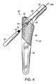
図7及び図8は、イヌの大腿骨12内に埋め込まれたステム及びポストシステム20を示しており、ポスト36は、大腿骨12の外側皮質50を貫通して突き出ている。これらの図の両方は、ポスト36が骨の厚くなっている領域内にアンカを提供して陥没の発生を阻止又は軽減する仕方を実証している。
FIGS. 7 and 8 show the stem and
図9及び図10は、上述の側方ポストを備えた大腿骨ステムの変形実施形態を示している。この変形実施形態では、側方ポスト36は、そのねじ山付き連結部42を越えて延びる延長案内ポスト又はロッド49を有する。延長案内ロッド49は、好ましくは、側方ポスト36の長手方向軸線と完全に整列する。延長案内ロッド49の直径は、好ましくは、案内穴48の内径と厳密に一致する一方で、依然として、延長案内ロッド49が最小の抵抗で案内穴48を通ることができるようにしている。延長案内ロッド49の目的は、ユーザがポート44内で側方ポスト36を適正に位置合わせして連結構造体42とこれとつがい関係をなす連結構造体46が適正に位置合わせされるようにするのを助けることにある。これの互いにつがい関係にある連結構造体がねじ山である場合、この適正な整列は、植え込み中における交差ねじ込みを最小限に抑えるのを助ける。
9 and 10 show a modified embodiment of the femoral stem with the side posts described above. In this alternative embodiment, the
図9及び図10は、ポート44及びポスト36の種々の長さの測定結果をさらに示している。図9及び図10に示されているように、距離Aは、ポート44の最も長い長手方向寸法の測定結果であるとともにポスト36の一部分に対応している。距離Aは、特定の患者に関して大腿骨ステムのサイズに応じて固定された距離であろう。ポスト36のこの対応の部分は、延長案内ロッド49が取り付けられている箇所でもある連結構造体42の先端部からポート44の最も長い長手方向寸法に対応したポスト36のほぼ中間点までまたがっている。距離Bは、ポート44の開口部、例えば、ステム22の側壁から大腿骨の外面、即ち外側皮質50までの距離を表している。この距離Bも図8に示されている。当業者には理解されるように、距離Bは、例えば種、成熟度のような要因、及び他の要因に応じて患者ごとに様々である大腿骨12のサイズに応じて様々であろう。距離Bは、上述したように深さゲージを用いることによって求められる。距離Cは、大腿骨12の外側皮質50から突き出たポスト36の部分を表し、即ち、大腿骨12の側壁からポスト36の露出端までの距離を表している。この距離Cは、ポスト36の陥没防止機能に外側皮質の強度を提供するのに十分に外側皮質50を貫通しなければならない。特に好ましい実施形態では、距離Cは、少なくとも2ミリメートルである。この距離Cも図8に示されている。
9 and 10 further show the measurement results of various lengths of the
幾つかの実施形態を例示目的で詳細に説明したが、本発明の範囲及び精神から逸脱することなく、種々の改造を行うことができる。したがって、本発明は、添付の特許請求の範囲の記載による以外に限定されることはない。 While several embodiments have been described in detail for purposes of illustration, various modifications may be made without departing from the scope and spirit of the invention. Accordingly, the invention is not limited except as by the appended claims.
Claims (18)
近位端部及び遠位端部を備えた全体として細長い形状を有する大腿骨底と、
前記大腿骨底の前記近位端部から延びるとともに同心軸線を備えた全体として管状の形状を有する大腿骨頸部と、
前記大腿骨頸部と全体として反対側に位置するとともに前記同心軸線と一線をなす前記大腿骨底の側部に設けられ、前記大腿骨頸部に近接するテーパ付き直径を備えた側方ポートと、
前記側方ポート内に取り外し可能に固定された第1の端部及び前記大腿骨底の前記側部から所定の距離にわたって延びる第2の端部を備えた側方ポストであって、前記第1の端部が、前記側方ポートの前記テーパ付き直径と一致するテーパ付き本体を備えた挿入先端部を備えた前記側方ポストと、を有する、大腿骨ステム。 A femoral stem for a hip prosthesis,
A femoral base having a generally elongated shape with a proximal end and a distal end;
A femoral neck having a generally tubular shape extending from the proximal end of the femoral base and having a concentric axis;
A lateral port located on the opposite side of the femoral neck as a whole and provided on the side of the bottom of the femur that is aligned with the concentric axis and having a tapered diameter close to the femoral neck; ,
A side post having a first end removably secured within the side port and a second end extending a predetermined distance from the side of the femoral base, the first post And a lateral post with an insertion tip with a tapered body coinciding with the tapered diameter of the lateral port.
前記大腿骨ステムの植え込みのために非ヒトの大腿骨の端部を前処理するステップと、 前記大腿骨ステムを前記非ヒトの大腿骨内に植え込むステップと、
前記大腿骨ステムの前記側方ポートに隣接して前記非ヒトの大腿骨の外側皮質に側方穴をあけるステップと、
前記側方穴を通って前記側方ポート中に前記側方ポストを設置して前記側方ポストの一部分が前記非ヒトの大腿骨の前記外側皮質から突き出るようにするステップと、を含む、方法。 A method of implanting the femoral stem of claim 1, comprising:
Pre-treating an end of a non-human femur for implantation of the femoral stem; implanting the femoral stem into the non-human femur;
Drilling a lateral hole in the lateral cortex of the non-human femur adjacent to the lateral port of the femoral stem;
Placing the side post through the side hole and into the side port so that a portion of the side post protrudes from the outer cortex of the non-human femur. .
前記側方穴の前記測定深さに基づいて前記側方ポストを選択して前記側方ポストが前記外側皮質から少なくとも2mmだけ突き出るようにするステップと、をさらに含む、請求項8記載の方法。 Measuring the depth of the side holes;
9. The method of claim 8, further comprising: selecting the side post based on the measured depth of the side hole so that the side post protrudes from the outer cortex by at least 2 mm.
非ヒトの大腿骨の頸部のレプリカとなる大腿骨頸部を有する大腿骨ステムを有するステップを含み、前記大腿骨ステムは、前記大腿骨頸部の同心軸線と一線をなして前記大腿骨頸部と全体として反対側に位置する前記大腿骨頸部の側部に設けられた側方ポートを有し、
前記大腿骨ステムの植え込みのために大腿骨の端部を前処理する前処理ステップと、
前記大腿骨ステムを前記大腿骨内に植え込むステップと、
前記大腿骨ステムの前記側方ポートに隣接して前記大腿骨の外側皮質に側方穴をあける穴あけステップと、
前記側方穴を通って前記側方ポート中に前記側方ポストを設置して前記側方ポストの一部分が前記大腿骨の前記外側皮質から突き出るようにするステップと、を含む、方法。 A method of implanting a femoral stem of an artificial hip joint into a non-human femur,
Comprising the step of having a femoral stem having a femoral neck comprising a neck replica of the femur of a non-human, the femoral stem, the femoral neck and forms concentric axis with clear distinction of the femoral neck A side port provided on the side of the femoral neck located on the opposite side of the part as a whole,
A pretreatment step of pretreating the end of the femur for implantation of the femoral stem;
Implanting the femoral stem into the femur;
Drilling a lateral hole in the lateral cortex of the femur adjacent to the lateral port of the femoral stem;
Placing the side post through the side hole and into the side port so that a portion of the side post protrudes from the outer cortex of the femur.
股関節部球窩に連結された大腿骨を含む非ヒトの股関節を露出させるステップと、
前記大腿骨を股関節部球窩から分離するステップと、
前記大腿骨の頭部及び頸部を切り取って前記大腿骨の内部を露出させるステップと、
前記大腿骨の前記露出内部をラスピングして前記大腿骨ステムを受け入れる腔を作るステップと、を含む、請求項10記載の方法。 The preprocessing step includes
Exposing a non-human hip joint including a femur coupled to a hip glenoid;
Separating the femur from the hip globules;
Cutting the head and neck of the femur to expose the interior of the femur;
11. The method of claim 10, comprising rasping the exposed interior of the femur to create a cavity for receiving the femoral stem.
第1のドリルビットを案内穴から前記大腿骨頸部の前記同心軸線に沿って挿入するとともに前記側方ポートから挿入して前記側方ポートに隣接したところで前記大腿骨に接触させるステップを含み、
前記第1のドリルビットを用いて前記大腿骨の前記外側皮質にパイロット穴をあけるステップを含み、前記パイロット穴は、前記側方ポート及び前記同心軸線と整列し、
前記案内ワイヤを前記案内穴、前記側方ポート、及び前記外側皮質の前記パイロット穴から挿入して前記案内ワイヤが前記大腿骨から突き出るようにするステップを含み、
第2のドリルビットを前記パイロット穴から突き出た前記案内ワイヤと整列させるステップを含み、
前記第2のドリルビットを用いて前記大腿骨頸部の前記同心軸線と一線をなして前記外側皮質に前記側方穴をあけるステップを含む、請求項10記載の方法。 The drilling step includes
Inserting a first drill bit from the guide hole along the concentric axis of the femoral neck and inserting from the side port to contact the femur at a location adjacent to the side port;
Drilling a pilot hole in the lateral cortex of the femur using the first drill bit, the pilot hole being aligned with the lateral port and the concentric axis;
Inserting the guide wire through the guide hole, the lateral port, and the pilot hole in the outer cortex, such that the guide wire protrudes from the femur;
Aligning a second drill bit with the guide wire protruding from the pilot hole;
The method of claim 10, comprising drilling the lateral hole in the outer cortex in line with the concentric axis of the femoral neck using the second drill bit.
前記大腿骨ステムを前記大腿骨の前記前処理端部に設けられた腔中に挿入するステップと、
前記大腿骨ステムを前記腔内に押し込むステップと、を含む、請求項10記載の方法。 The implantation step includes
Inserting the femoral stem into a cavity provided in the pretreated end of the femur;
11. The method of claim 10, comprising pushing the femoral stem into the cavity.
前記側方穴の前記測定深さに基づいて前記側方ポストを選択して前記側方ポストが少なくとも2mmだけ前記外側皮質から突き出るようにするステップと、をさらに含む、請求項10記載の方法。 Measuring the depth of the side holes;
The method of claim 10, further comprising: selecting the side post based on the measured depth of the side hole so that the side post protrudes from the outer cortex by at least 2 mm.
Applications Claiming Priority (5)
| Application Number | Priority Date | Filing Date | Title |
|---|---|---|---|
| US201462047566P | 2014-09-08 | 2014-09-08 | |
| US62/047,566 | 2014-09-08 | ||
| US14/846,509 US9730798B2 (en) | 2014-09-08 | 2015-09-04 | Femoral stem and post system for hip prosthesis |
| US14/846,509 | 2015-09-04 | ||
| PCT/US2015/048901 WO2016040296A1 (en) | 2014-09-08 | 2015-09-08 | Femoral stem and post system for hip prosthesis |
Publications (3)
| Publication Number | Publication Date |
|---|---|
| JP2017526516A JP2017526516A (en) | 2017-09-14 |
| JP2017526516A5 JP2017526516A5 (en) | 2017-11-24 |
| JP6408158B2 true JP6408158B2 (en) | 2018-10-17 |
Family
ID=55436427
Family Applications (1)
| Application Number | Title | Priority Date | Filing Date |
|---|---|---|---|
| JP2017533165A Active JP6408158B2 (en) | 2014-09-08 | 2015-09-08 | Femoral stem and post stem for hip prosthesis |
Country Status (5)
| Country | Link |
|---|---|
| US (2) | US9730798B2 (en) |
| EP (1) | EP3191028B1 (en) |
| JP (1) | JP6408158B2 (en) |
| AU (1) | AU2015315398B2 (en) |
| WO (1) | WO2016040296A1 (en) |
Families Citing this family (1)
| Publication number | Priority date | Publication date | Assignee | Title |
|---|---|---|---|---|
| KR102350091B1 (en) * | 2019-10-23 | 2022-01-12 | 주식회사 비트러스트메디텍 | Femoral Implant for Animals |
Family Cites Families (11)
| Publication number | Priority date | Publication date | Assignee | Title |
|---|---|---|---|---|
| US3896505A (en) * | 1970-03-31 | 1975-07-29 | Franz Donatus Timmermans | Endoprosthesis for the hipjoint |
| FR2673831A1 (en) * | 1991-03-11 | 1992-09-18 | Rech Fabrication Et | Femoral shaft for a hip prosthesis, and its method of manufacture |
| FR2746001B1 (en) * | 1996-03-12 | 1998-06-12 | ORTHOPEDIC SURGERY ASSEMBLY FOR HIP PROSTHESIS WITH REMOVABLE NECK | |
| WO2000048535A1 (en) * | 1999-02-19 | 2000-08-24 | Grimes James B | Bone prosthesis and method of implantation |
| JP3692229B2 (en) * | 1998-01-30 | 2005-09-07 | 京セラ株式会社 | Artificial hip joint |
| DE10036985A1 (en) * | 2000-07-29 | 2002-02-07 | Klaus Draenert | Femur component of artificial hip joint for cement-free implantation comprises prosthesis whose shaft has no bearing collar and whose constructional axis coincides with the femur channel axis |
| AU2006201044B2 (en) * | 2001-03-13 | 2009-06-18 | Nicholas G. Sotereanos | Hip implant assembly |
| US7179264B2 (en) * | 2002-08-28 | 2007-02-20 | Depuy Products, Inc. | Cemented prosthetic kit |
| EP1498090A1 (en) * | 2003-07-16 | 2005-01-19 | WALDEMAR LINK GmbH & Co. KG | Hip prosthesis with femoral shaft |
| US7608112B1 (en) * | 2004-09-13 | 2009-10-27 | Howmedica Osteonics Corp. | Hip arthroplasty trialing apparatus and method |
| WO2010050252A1 (en) * | 2008-10-31 | 2010-05-06 | 株式会社ロバート・リード商会 | Bone fixing material and thighbone fixing system |
-
2015
- 2015-09-04 US US14/846,509 patent/US9730798B2/en active Active
- 2015-09-08 WO PCT/US2015/048901 patent/WO2016040296A1/en active Application Filing
- 2015-09-08 EP EP15840244.6A patent/EP3191028B1/en active Active
- 2015-09-08 JP JP2017533165A patent/JP6408158B2/en active Active
- 2015-09-08 AU AU2015315398A patent/AU2015315398B2/en active Active
-
2017
- 2017-06-30 US US15/639,076 patent/US10166107B2/en active Active
Also Published As
| Publication number | Publication date |
|---|---|
| US20170296348A1 (en) | 2017-10-19 |
| US10166107B2 (en) | 2019-01-01 |
| AU2015315398A1 (en) | 2017-03-02 |
| WO2016040296A1 (en) | 2016-03-17 |
| EP3191028B1 (en) | 2019-11-27 |
| JP2017526516A (en) | 2017-09-14 |
| AU2015315398B2 (en) | 2019-12-12 |
| NZ728884A (en) | 2021-01-29 |
| US9730798B2 (en) | 2017-08-15 |
| US20160067047A1 (en) | 2016-03-10 |
| EP3191028A1 (en) | 2017-07-19 |
| EP3191028A4 (en) | 2018-04-11 |
Similar Documents
| Publication | Publication Date | Title |
|---|---|---|
| US20210236292A1 (en) | System and method for implanting a secondary glenoid prosthesis | |
| US20210244547A1 (en) | Methods and devices for less invasive glenoid replacement | |
| US4976740A (en) | Anchored femoral dome | |
| US20130190882A1 (en) | Humeral Head Prosthesis | |
| US20120179268A1 (en) | Metatarsal Implant | |
| JP2010099496A (en) | Articular surface implant | |
| US11957595B2 (en) | Methods and devices for less invasive glenoid replacement | |
| US10028752B2 (en) | Brosteotome and method of use | |
| JP6408158B2 (en) | Femoral stem and post stem for hip prosthesis | |
| EP3395297B1 (en) | Osteochondral local prosthetic insert | |
| NZ728884B2 (en) | Femoral stem and post system for hip prosthesis | |
| WO2006092613A2 (en) | Hip replacement device and method | |
| GB2535767A (en) | Buffer for femoral head and neck excision | |
| GB2434749A (en) | Hip prosthesis |
Legal Events
| Date | Code | Title | Description |
|---|---|---|---|
| A521 | Request for written amendment filed |
Free format text: JAPANESE INTERMEDIATE CODE: A523 Effective date: 20171016 |
|
| A621 | Written request for application examination |
Free format text: JAPANESE INTERMEDIATE CODE: A621 Effective date: 20171016 |
|
| A977 | Report on retrieval |
Free format text: JAPANESE INTERMEDIATE CODE: A971007 Effective date: 20180629 |
|
| A131 | Notification of reasons for refusal |
Free format text: JAPANESE INTERMEDIATE CODE: A131 Effective date: 20180709 |
|
| A521 | Request for written amendment filed |
Free format text: JAPANESE INTERMEDIATE CODE: A523 Effective date: 20180822 |
|
| TRDD | Decision of grant or rejection written | ||
| A01 | Written decision to grant a patent or to grant a registration (utility model) |
Free format text: JAPANESE INTERMEDIATE CODE: A01 Effective date: 20180827 |
|
| A61 | First payment of annual fees (during grant procedure) |
Free format text: JAPANESE INTERMEDIATE CODE: A61 Effective date: 20180919 |
|
| R150 | Certificate of patent or registration of utility model |
Ref document number: 6408158 Country of ref document: JP Free format text: JAPANESE INTERMEDIATE CODE: R150 |
|
| R250 | Receipt of annual fees |
Free format text: JAPANESE INTERMEDIATE CODE: R250 |
|
| R250 | Receipt of annual fees |
Free format text: JAPANESE INTERMEDIATE CODE: R250 |
|
| R250 | Receipt of annual fees |
Free format text: JAPANESE INTERMEDIATE CODE: R250 |