JP6408132B2 - Battery pack including indicator circuit - Google Patents
Battery pack including indicator circuit Download PDFInfo
- Publication number
- JP6408132B2 JP6408132B2 JP2017509010A JP2017509010A JP6408132B2 JP 6408132 B2 JP6408132 B2 JP 6408132B2 JP 2017509010 A JP2017509010 A JP 2017509010A JP 2017509010 A JP2017509010 A JP 2017509010A JP 6408132 B2 JP6408132 B2 JP 6408132B2
- Authority
- JP
- Japan
- Prior art keywords
- battery pack
- battery
- case
- electrochemical cell
- circuit
- Prior art date
- Legal status (The legal status is an assumption and is not a legal conclusion. Google has not performed a legal analysis and makes no representation as to the accuracy of the status listed.)
- Active
Links
Images


Classifications
-
- H—ELECTRICITY
- H01—ELECTRIC ELEMENTS
- H01M—PROCESSES OR MEANS, e.g. BATTERIES, FOR THE DIRECT CONVERSION OF CHEMICAL ENERGY INTO ELECTRICAL ENERGY
- H01M10/00—Secondary cells; Manufacture thereof
- H01M10/42—Methods or arrangements for servicing or maintenance of secondary cells or secondary half-cells
- H01M10/425—Structural combination with electronic components, e.g. electronic circuits integrated to the outside of the casing
- H01M10/4257—Smart batteries, e.g. electronic circuits inside the housing of the cells or batteries
-
- H—ELECTRICITY
- H01—ELECTRIC ELEMENTS
- H01M—PROCESSES OR MEANS, e.g. BATTERIES, FOR THE DIRECT CONVERSION OF CHEMICAL ENERGY INTO ELECTRICAL ENERGY
- H01M10/00—Secondary cells; Manufacture thereof
- H01M10/42—Methods or arrangements for servicing or maintenance of secondary cells or secondary half-cells
- H01M10/48—Accumulators combined with arrangements for measuring, testing or indicating the condition of cells, e.g. the level or density of the electrolyte
- H01M10/482—Accumulators combined with arrangements for measuring, testing or indicating the condition of cells, e.g. the level or density of the electrolyte for several batteries or cells simultaneously or sequentially
-
- H—ELECTRICITY
- H01—ELECTRIC ELEMENTS
- H01M—PROCESSES OR MEANS, e.g. BATTERIES, FOR THE DIRECT CONVERSION OF CHEMICAL ENERGY INTO ELECTRICAL ENERGY
- H01M10/00—Secondary cells; Manufacture thereof
- H01M10/42—Methods or arrangements for servicing or maintenance of secondary cells or secondary half-cells
- H01M10/48—Accumulators combined with arrangements for measuring, testing or indicating the condition of cells, e.g. the level or density of the electrolyte
- H01M10/488—Cells or batteries combined with indicating means for external visualization of the condition, e.g. by change of colour or of light density
-
- H—ELECTRICITY
- H01—ELECTRIC ELEMENTS
- H01M—PROCESSES OR MEANS, e.g. BATTERIES, FOR THE DIRECT CONVERSION OF CHEMICAL ENERGY INTO ELECTRICAL ENERGY
- H01M50/00—Constructional details or processes of manufacture of the non-active parts of electrochemical cells other than fuel cells, e.g. hybrid cells
- H01M50/20—Mountings; Secondary casings or frames; Racks, modules or packs; Suspension devices; Shock absorbers; Transport or carrying devices; Holders
- H01M50/204—Racks, modules or packs for multiple batteries or multiple cells
- H01M50/207—Racks, modules or packs for multiple batteries or multiple cells characterised by their shape
- H01M50/213—Racks, modules or packs for multiple batteries or multiple cells characterised by their shape adapted for cells having curved cross-section, e.g. round or elliptic
-
- H—ELECTRICITY
- H01—ELECTRIC ELEMENTS
- H01M—PROCESSES OR MEANS, e.g. BATTERIES, FOR THE DIRECT CONVERSION OF CHEMICAL ENERGY INTO ELECTRICAL ENERGY
- H01M50/00—Constructional details or processes of manufacture of the non-active parts of electrochemical cells other than fuel cells, e.g. hybrid cells
- H01M50/20—Mountings; Secondary casings or frames; Racks, modules or packs; Suspension devices; Shock absorbers; Transport or carrying devices; Holders
- H01M50/284—Mountings; Secondary casings or frames; Racks, modules or packs; Suspension devices; Shock absorbers; Transport or carrying devices; Holders with incorporated circuit boards, e.g. printed circuit boards [PCB]
-
- H—ELECTRICITY
- H01—ELECTRIC ELEMENTS
- H01M—PROCESSES OR MEANS, e.g. BATTERIES, FOR THE DIRECT CONVERSION OF CHEMICAL ENERGY INTO ELECTRICAL ENERGY
- H01M50/00—Constructional details or processes of manufacture of the non-active parts of electrochemical cells other than fuel cells, e.g. hybrid cells
- H01M50/20—Mountings; Secondary casings or frames; Racks, modules or packs; Suspension devices; Shock absorbers; Transport or carrying devices; Holders
- H01M50/296—Mountings; Secondary casings or frames; Racks, modules or packs; Suspension devices; Shock absorbers; Transport or carrying devices; Holders characterised by terminals of battery packs
-
- Y—GENERAL TAGGING OF NEW TECHNOLOGICAL DEVELOPMENTS; GENERAL TAGGING OF CROSS-SECTIONAL TECHNOLOGIES SPANNING OVER SEVERAL SECTIONS OF THE IPC; TECHNICAL SUBJECTS COVERED BY FORMER USPC CROSS-REFERENCE ART COLLECTIONS [XRACs] AND DIGESTS
- Y02—TECHNOLOGIES OR APPLICATIONS FOR MITIGATION OR ADAPTATION AGAINST CLIMATE CHANGE
- Y02E—REDUCTION OF GREENHOUSE GAS [GHG] EMISSIONS, RELATED TO ENERGY GENERATION, TRANSMISSION OR DISTRIBUTION
- Y02E60/00—Enabling technologies; Technologies with a potential or indirect contribution to GHG emissions mitigation
- Y02E60/10—Energy storage using batteries
Description
本発明は、インジケータ回路を含むバッテリーパックに関する。 The present invention relates to a battery pack including an indicator circuit.
無線周波数識別(RFID:Radio Frequency Identification)及び他の近距離無線通信(NFC)プロトコルを含む無線通信は、セキュリティ、在庫管理、アクセス・コントロールなどの分野において、人気が増大している。RFIDまたはNFCのプロトコルを含んでいるスマートフォンの数は、RFID回路及びNFC回路のような受動又は能動トランスポンダの様々な分野と共に、増大している。そのような通信回路は、変調するアンテナと結合されてもよいし、また、いくつかの実施例では、スマートフォンのようなリーダによって読むことができる無線通信信号を発信してもよい。 Wireless communications, including Radio Frequency Identification (RFID) and other Near Field Communication (NFC) protocols, are gaining popularity in areas such as security, inventory management, and access control. The number of smartphones that include RFID or NFC protocols is increasing along with various areas of passive or active transponders such as RFID and NFC circuits. Such a communication circuit may be coupled to a modulating antenna, and in some embodiments may emit a wireless communication signal that can be read by a reader such as a smartphone.
電気化学セル、すなわちバッテリーは、電気エネルギー源として一般に使用される。電気化学セルは、典型的にはアノードと呼ぶ陰極と、典型的にはカソードを呼ぶ陽極とを、含んでいる。アノードは、酸化することができる活物質を含んでいる。カソードは、還元することができる活物質を含んでいる。アノード活物質はカソード活物質を還元することができる。セパレーターが、アノードとカソードの間に配置されている。電解質も電気化学セル内に含まれている。前述の構成部品は、一般的に、1つの缶に配置される。バッテリーパックは、ケース内に少なくとも1つの電気化学セルを含んでいてもよい。バッテリーパックは、一部分において、少なくとも1つの電気化学セル及び他のバッテリーパック構成部品に利用可能なケースの内容積を制限する、外部の寸法を指定してもよい。 Electrochemical cells, or batteries, are commonly used as electrical energy sources. The electrochemical cell includes a cathode, typically referred to as the anode, and an anode, typically referred to as the cathode. The anode contains an active material that can be oxidized. The cathode contains an active material that can be reduced. The anode active material can reduce the cathode active material. A separator is disposed between the anode and the cathode. An electrolyte is also included in the electrochemical cell. The aforementioned components are generally placed in one can. The battery pack may include at least one electrochemical cell in the case. The battery pack may specify external dimensions that, in part, limit the internal volume of the case that is available for at least one electrochemical cell and other battery pack components.
バッテリーテスターは、残りの電池性能のような、バッテリー、或いはバッテリーパックの特性を、決定するために使用されてもよい。バッテリーに置かれる典型的なタイプのバッテリーテスターの例示的なタイプは、サーモクロミックタイプのテスターとして知られている。サーモクロミックのバッテリーテスターにおいては、消費者が手動で1つ或いは2つのボタンスイッチを押し下げることによって、回路が完成するかもしれない。一旦回路が完成すれば、消費者はサーモクロミックのテスターに電気的にバッテリーを接続する。サーモクロミックのテスターは、銀の抵抗器を、例えば電気抵抗がその長さに沿って変わるように可変幅を有している平面の銀のレイヤを、含んでいるかもしれない。電流が銀の抵抗器を流れるにしたがって、消費された電力は熱を生成し、銀の抵抗器上に置かれたサーモクロミックのインク表示器のカラーを変更する。バッテリーの相対的な容量を示すために、サーモクロミックのインク表示器はゲージとして配置されていてもよい。しかしながら、消費者が不便にバッテリーを保持することが、及び/又は、バッテリーテスターを使用して、バッテリーをテストするためにデバイスからバッテリーを取り外すことが、典型的に必要である。 A battery tester may be used to determine battery or battery pack characteristics, such as remaining battery performance. An exemplary type of a typical type of battery tester that is placed in a battery is known as a thermochromic type tester. In a thermochromic battery tester, the circuit may be completed by a consumer manually depressing one or two button switches. Once the circuit is complete, the consumer electrically connects the battery to a thermochromic tester. Thermochromic testers may include a silver resistor, for example, a planar silver layer having a variable width such that the electrical resistance varies along its length. As the current flows through the silver resistor, the consumed power generates heat and changes the color of the thermochromic ink indicator placed on the silver resistor. To indicate the relative capacity of the battery, the thermochromic ink indicator may be arranged as a gauge. However, it is typically necessary for the consumer to hold the battery inconveniently and / or to remove the battery from the device to test the battery using a battery tester.
従って、消費者とバッテリーパックの間のマニュアル・インタラクションを必要としないインジケータ回路を含むバッテリーパックの必要性が存在する。さらに、インジケータ回路を含むバッテリーパックは、先進的な処理能力と通信能力を含んでいてもよい。少なくとも1つの電気化学セル及び他のバッテリーパック構成部品に利用可能なケースの内容積を、有害に縮小しないインジケータ回路を含むバッテリーパックの必要性も存在する。 Accordingly, there is a need for a battery pack that includes an indicator circuit that does not require manual interaction between the consumer and the battery pack. In addition, the battery pack that includes the indicator circuit may include advanced processing and communication capabilities. There is also a need for a battery pack that includes an indicator circuit that does not detrimentally reduce the internal volume of the case available for at least one electrochemical cell and other battery pack components.
本発明は、バッテリーパックに関する。バッテリーパックは、少なくとも1つの電気化学セルと、ケースと、プレートと、インジケータ回路と、バッテリー対内容積の比率を、含んでいる。ケースは、少なくとも1つの開放端を含んでいる。プレートは少なくとも1つの開放端の上方に置かれる。プレートは、ターミナルプレート、ベースプレート、又は、その任意の組み合わせを含んでいる。インジケータ回路は、集積回路とアンテナを含んでいる。インジケータ回路は、プレートに取り付けられる。バッテリー対内容積の比率は、約0.52より大きい。 The present invention relates to a battery pack. The battery pack includes at least one electrochemical cell, a case, a plate, an indicator circuit, and a battery to internal volume ratio. The case includes at least one open end. The plate is placed over at least one open end. The plate includes a terminal plate, a base plate, or any combination thereof. The indicator circuit includes an integrated circuit and an antenna. The indicator circuit is attached to the plate. The battery to internal volume ratio is greater than about 0.52.
別の実施形態では、本発明はバッテリーパックに関する。バッテリーパックは、少なくとも1つの電気化学セルと、ケースと、プレートと、インジケータ回路と、バッテリー対内容積の比率を含んでいる。ケースは、開放端と、閉鎖端と、それらの間のサイドウォールを含んでいる。プレートは、1つの開放端の上方に置かれる。プレートは、ターミナルプレートである。インジケータ回路は、集積回路とアンテナを含んでいる。インジケータ回路は、ケースの閉鎖端に取り付けられる。バッテリー対内容積の比率は、約0.52より大きい。 In another embodiment, the present invention relates to a battery pack. The battery pack includes at least one electrochemical cell, a case, a plate, an indicator circuit, and a battery to internal volume ratio. The case includes an open end, a closed end, and a sidewall therebetween. The plate is placed over one open end. The plate is a terminal plate. The indicator circuit includes an integrated circuit and an antenna. The indicator circuit is attached to the closed end of the case. The battery to internal volume ratio is greater than about 0.52.
明細書は、本発明を形成すると見なされる主題を、特に指摘し、且つ、明確に要求するクレームで締めくくっているが、添付図面と共に得られた以下の記述から、本発明は一層よく理解されるであろう。
本発明は、インジケータ回路を含むバッテリーパックに関する。バッテリーパックは、ケース内の少なくとも1つの電気化学セル、すなわちバッテリーを含んでいる。インジケータ回路は、無線通信信号を送ることができ、及び/又は、受け取ることができる。インジケータ回路は、集積回路(IC)及びアンテナを含んでいる。インジケータ回路は、少なくとも1つの電気化学セルに電気的に結合されてもよい。インジケータ回路は、無線でスマートフォンのようなリーダに、電圧または容量のような少なくとも1つの電気化学セルの特性を伝えてもよい。 The present invention relates to a battery pack including an indicator circuit. The battery pack includes at least one electrochemical cell, or battery, in the case. The indicator circuit can send and / or receive wireless communication signals. The indicator circuit includes an integrated circuit (IC) and an antenna. The indicator circuit may be electrically coupled to at least one electrochemical cell. The indicator circuit may wirelessly communicate characteristics of at least one electrochemical cell, such as voltage or capacity, to a reader such as a smartphone.
電気化学セルは、電気化学的な還元−酸化(レドックス)反応により、電気化学セルの活物質内の化学エネルギーを変換することができるデバイスである。デービッド・リンデン(David Linden)、バッテリー、1.3(第4版、2011)のハンドブックを参照されたい。電気化学セルは、アノード、カソード及び電解質から成る。同文献を参照された。1つ以上の電気化学セルが、バッテリーと呼ばれてもよい。電気化学セル、すなわちバッテリーは、一次でもよいし、二次でもよい。一次電池は、放電を意図されており、例えば、一度だけ消耗され、そして、廃棄される。一次電池は、デービッド・リンデン、バッテリー(第4版、2011)のハンドブックに、例えば開示される。二次電池は、充電されることを意図されている。二次電池は、何度も放電され充電されてもよく、例えば50回以上、100回、それ以上である。二次電池は、デービッド・リンデン、バッテリー、(第4版、2011)のハンドブックで、例えば開示される。従って、バッテリーは、様々な電気化学の結合及び電解質の組み合わせを含んでいてもよい。バッテリーパック内に含まれる、水溶液系、非水溶液系、イオン液体系、及び、ソリッドステート系の一次電池及び二次電池の両方に、本発明が当てはまることが認識されるべきである。故に、前述した系の一次電池及び二次電池を含むバッテリーパックは、本願の範囲内であり、また、本発明はいずれの特別な実施形態に限定されない。 An electrochemical cell is a device that can convert chemical energy in the active material of an electrochemical cell by an electrochemical reduction-oxidation (redox) reaction. See the handbook of David Linden, Battery, 1.3 (4th edition, 2011). The electrochemical cell consists of an anode, a cathode and an electrolyte. Reference was made to the same document. One or more electrochemical cells may be referred to as a battery. The electrochemical cell, i.e., battery, may be primary or secondary. Primary batteries are intended to be discharged, for example, consumed once and then discarded. Primary batteries are disclosed, for example, in the handbook of David Linden, Battery (4th edition, 2011). A secondary battery is intended to be charged. The secondary battery may be discharged and charged many times, for example, 50 times or more, 100 times or more. Secondary batteries are disclosed, for example, in the handbook of David Linden, Battery, (4th edition, 2011). Thus, the battery may contain various electrochemical bonds and electrolyte combinations. It should be appreciated that the present invention applies to both aqueous, non-aqueous, ionic liquid, and solid state primary and secondary batteries contained within a battery pack. Therefore, a battery pack including the above-described primary and secondary batteries is within the scope of the present application, and the present invention is not limited to any particular embodiment.
バッテリーパックは、サイズと寸法を変えて利用可能である。国際電気標準会議(IEC)及び米国規格協会(ANSI)は、例えば、小売りの消費者に利用可能なバッテリー及びバッテリーパックに関する標準的なサイズ及び寸法を確立している。IECは、9Vのアルカリ電池パックと一般に呼ばれるようなバッテリーパックに関して、例えば、標準的なサイズと寸法を設定している。9Vのバッテリーパックは、例えば、約48.5mmの最大高さ、約26.5mmの最大長さ、約17.5mmの最大幅を備えた、角柱状、又は、長方形の形状を有している。さらに、個々のバッテリー或いはデバイス・メーカーは、リチウム・イオン角柱バッテリーのような、小売りで一般に利用可能でないかもしれないバッテリーパックに関して、寸法を指定してもよい。このタイプの角柱バッテリーは、約5mm未満の高さ、約42mm未満の長さ、約34mm未満の幅を備えていても良い。個々のバッテリー又はデバイス・メーカーで示されるバッテリーパック・サイズ及び寸法と同様に、ANSI 1604バッテリーパック、ANSI 7.2H5バッテリーパック、ANSI 7.2K5バッテリーパック、ANSI 8.4H5バッテリーパック、及び、ANSI 8.4K5バッテリーのような、IEC又はANSIによって設定された、様々なサイズ及び寸法のバッテリーパックに、本発明が適用されることが認識されるべきである。 Battery packs can be used in varying sizes and dimensions. The International Electrotechnical Commission (IEC) and the American National Standards Institute (ANSI) have established standard sizes and dimensions for batteries and battery packs available to retail consumers, for example. The IEC sets, for example, standard sizes and dimensions for battery packs commonly referred to as 9V alkaline battery packs. The 9V battery pack has, for example, a prismatic or rectangular shape with a maximum height of about 48.5 mm, a maximum length of about 26.5 mm, and a maximum width of about 17.5 mm. . In addition, individual batteries or device manufacturers may specify dimensions for battery packs that may not be generally available at retail, such as lithium ion prismatic batteries. This type of prismatic battery may have a height less than about 5 mm, a length less than about 42 mm, and a width less than about 34 mm. Similar to the battery pack sizes and dimensions indicated by individual battery or device manufacturers, ANSI 1604 battery pack, ANSI 7.2H5 battery pack, ANSI 7.2K5 battery pack, ANSI 8.4H5 battery pack, and ANSI 8 It should be appreciated that the present invention applies to battery packs of various sizes and dimensions set by IEC or ANSI, such as .4K5 batteries.
ケースは、何らかの適切な形(例えば角柱形、長円形、完全なエッジを備えた多角形の形、他の適切な形)を有していてよい。ケースは、角柱形(例えば長方形か正方形の形のような、少なくとも2つの平行平板電極を含む形)があるかもしれない。ケースは、バッテリーパックに一般に使用される任意の従来型かもしれない。ケースは、任意の適切な材料で作られていてもよい。材料は、例えば、アルミニウム、アルミニウム合金、ステンレス鋼、ニッケルをめっきした(事前に或いは事後的にめっきされた)鋼などのような、柔軟な金属かもしれない。例えば、材料は、プラスチック、ポリマーなどのような非伝導性及び非磁性の材料かもしれない。ケースは、少なくとも1つの電気化学セル及びインジケータ回路を含めるために、十分な寸法及び内容積を有しているべきである。 The case may have any suitable shape (eg prismatic shape, oval, polygonal shape with perfect edges, other suitable shapes). The case may have a prismatic shape (eg, a shape including at least two parallel plate electrodes, such as a rectangular or square shape). The case may be any conventional type commonly used for battery packs. The case may be made of any suitable material. The material may be a flexible metal such as, for example, aluminum, aluminum alloy, stainless steel, nickel plated (pre- or post-plated) steel, and the like. For example, the material may be a non-conductive and non-magnetic material such as plastic, polymer, etc. The case should have sufficient dimensions and internal volume to contain at least one electrochemical cell and indicator circuit.
ケースは、絞り加工のようなスタンピング工程によって形成されるかもしれない。ケースは、射出成形のような成型加工によって形成されるかもしれない。ケースは、例えば完全なケースを形成するために互いに組み合わされる2つの部分により形成されてもよく、そのようなケースはクラムシェル・ケースと呼ばれてもよい。ケースは少なくとも1つの開放端を含んでいてもよい。ケースが例えば絞り加工又は射出成形のいずれかによって形成される場合、ケース内に一体に形成される閉鎖端をケースが備えていてもよい。閉鎖端は、ケースの開放端に対向していてもよい。ケースは、第1の開放端及び第2の開放端を含んでいてもよい。ケースは、ケースの開放端から閉鎖端へ延びるサイドウォールを含んでいてもよい。ケースは、ケースの第1の開放端からケースの第2の開放端へ延びるサイドウォールを含んでいてもよい。サイドウォールは高さHを有していてもよい。プレートは、少なくとも1つの開放端の上方に置かれてもよい。プレートは、ターミナルプレートまたはベースプレートでもよい。 The case may be formed by a stamping process such as drawing. The case may be formed by a molding process such as injection molding. The case may be formed, for example, by two parts that are combined together to form a complete case, such a case may be referred to as a clamshell case. The case may include at least one open end. When the case is formed, for example, by either drawing or injection molding, the case may include a closed end formed integrally in the case. The closed end may face the open end of the case. The case may include a first open end and a second open end. The case may include a sidewall that extends from the open end of the case to the closed end. The case may include a sidewall that extends from the first open end of the case to the second open end of the case. The sidewall may have a height H. The plate may be placed above the at least one open end. The plate may be a terminal plate or a base plate.
ターミナルプレートは、バッテリーパックを閉じるために、ケースの少なくとも1つの開放端の上方に載置されてもよい。バッテリーパックがクラムシェル・ケースを含んでいるようないくつかの実施形態では、ターミナルプレートはケースの第1の開放端の上方に載置されてもよい。ターミナルプレートは、任意の適切な材料から作られてもよい。材料は、例えばアルミニウム、アルミニウム合金、ステンレス鋼、又は、ニッケルをめっきした(事前に或いは事後的にめっきされた)鋼などのような、柔軟な金属でもよい。例えば、材料は、プラスチック、ポリマーなどのような非伝導性及び非磁性の材料でもよい。ターミナルプレートは、絞り加工または射出成形のような任意の適切なプロセスによって形成されてもよい。ターミナルプレートは、正のバッテリーパック・ターミナル及び負のバッテリーパック・ターミナルを含んでいてもよい。正のバッテリーパック・ターミナル及び負のバッテリーパック・ターミナルは、伝導性のいかなる適切な材料から作られてもよい。材料は、ニッケル、ニッケルをめっきした鋼、ステンレス鋼、黄銅などのような金属でもよい。正のバッテリーパック・ターミナル及び負のバッテリーパック・ターミナルは、ニッケル、金、黄銅、或いは、正のバッテリーパック・ターミナル及び負のバッテリーパック・ターミナルと、正のバッテリーパック・ターミナル及び負のバッテリーパック・ターミナルがデバイスと電気的に導通するデバイス内の電気コンタクトとの間に、低い電気的接触抵抗をもたらす別の適切な材料で、任意にめっきされてもよい。 The terminal plate may be placed over at least one open end of the case to close the battery pack. In some embodiments where the battery pack includes a clamshell case, the terminal plate may be placed over the first open end of the case. The terminal plate may be made from any suitable material. The material may be a flexible metal, such as, for example, aluminum, aluminum alloy, stainless steel, or nickel plated (pre- or post-plated) steel. For example, the material may be a non-conductive and non-magnetic material such as plastic, polymer, etc. The terminal plate may be formed by any suitable process such as drawing or injection molding. The terminal plate may include a positive battery pack terminal and a negative battery pack terminal. The positive battery pack terminal and the negative battery pack terminal may be made from any suitable material that is conductive. The material may be a metal such as nickel, nickel-plated steel, stainless steel, brass or the like. The positive battery pack terminal and the negative battery pack terminal are nickel, gold, brass, or the positive battery pack terminal and the negative battery pack terminal, and the positive battery pack terminal and the negative battery pack terminal. Between the electrical contacts in the device where the terminal is in electrical communication with the device, it may optionally be plated with another suitable material that provides a low electrical contact resistance.
ターミナルプレートがケースの少なくとも1つの開放端内に位置する場合、ケースのサイドウォールの一部はターミナルプレートを過ぎて伸びてもよい。閉じたバッテリーパックのケースを密閉するために、位置させたターミナルプレートを過ぎて伸びるケースのサイドウォールの部分は、ターミナルプレート上で圧着させることができる。或いは、ターミナルプレートは、例えばクラムシェル・ケースの二等分内に置かれてもよい。クラムシェル・ケースの二等分はバッテリーパックを閉じるために溶接されてもよく、例えば超音波で溶接されてもよい。 If the terminal plate is located within at least one open end of the case, a portion of the case sidewall may extend past the terminal plate. To seal the closed battery pack case, the portion of the case sidewall that extends past the terminal plate positioned can be crimped onto the terminal plate. Alternatively, the terminal plate may be placed in, for example, a bisection of a clamshell case. The halves of the clamshell case may be welded to close the battery pack, for example ultrasonically.
バッテリーパックが、クラムシェル・ケースを含んでいるかのようないくつかの実施形態では、ベースプレートが使用されてもよい。ベースプレートは、バッテリーパックを形成するケースの第2の開放端を閉じるために、ケースの第2の開放端の上方に載置されてもよい。ベースプレートは任意の適切な材料から作られてもよい。材料は、例えばアルミニウム、アルミニウム合金、ステンレス鋼、ニッケルをめっきした(事前に或いは事後的にめっきされた)鋼などのような、柔軟な金属でもよい。材料は、例えば、プラスチック、ポリマーなどのような非伝導性及び非磁性の材料からでもよい。ベースプレートは、絞り加工または射出成形のような任意の適切なプロセスによって形成されてもよい。 In some embodiments, such as if the battery pack includes a clamshell case, a base plate may be used. The base plate may be placed above the second open end of the case to close the second open end of the case forming the battery pack. The base plate may be made from any suitable material. The material may be a flexible metal such as, for example, aluminum, aluminum alloy, stainless steel, nickel plated (pre- or post-plated) steel, and the like. The material may be from non-conductive and non-magnetic materials such as plastics, polymers and the like. The base plate may be formed by any suitable process such as drawing or injection molding.
ベースプレートは、ケースの第2の開放端の上方に載置されてもよい。ベースプレートがケースの第2の開放端内に据え付けられる場合、ケースのサイドウォールの一部はベースプレートを過ぎて伸びてもよい。閉じたバッテリーパックのケースを密閉するために、据え付けられたベースプレートを過ぎて伸びるケースのサイドウォールの部分は、ベースプレートの上方で圧着させることができる。或いは、ベースプレートは、例えばクラムシェル・ケースの二等分内に置かれてもよい。クラムシェル・ケースの二等分はバッテリーパックを閉じるために溶接されてもよく、例えば超音波で溶接されてもよい。 The base plate may be placed above the second open end of the case. If the base plate is installed in the second open end of the case, a portion of the case sidewall may extend past the base plate. To seal the closed battery pack case, the portion of the case sidewall that extends past the installed base plate can be crimped over the base plate. Alternatively, the base plate may be placed in, for example, a bisection of a clamshell case. The halves of the clamshell case may be welded to close the battery pack, for example ultrasonically.
インジケータ回路は、集積回路(IC)及びアンテナを含んでいてもよい。ICは、トランジスター、抵抗器、ダイオード、誘導子及び/又は半導体ウェーハ又はチップのような単一の基板或いは金属に構築されたコンデンサーの回路、ポリマー或いはセラミック基板を含んでいてもよく、与えられた機能を行なうためにその中で個別の構成部品は相互に連結される。ICは通信回路、機能を行なうために電気的に互いに結合されたA−D変換器(ADC)、或いは任意の数の機能を含んでもよい。ICは、ICがその機能を行なうために、システムグランドに電気的に接続されてもよい。ICは、制限されるものではないが、指示回路、電源回路、RFID回路又はブロック、或いはNFC回路又は、ブロックのような通信回路、入出力回路又はポート、また同種のものを含む回路を含んでいてもよい。ICは物理的に、例えば、並んで通信回路及びADCを同じ場所を共用するか、或いは物理的に、それらをともに集積化してもよい。ICは、さらに機能のパフォーマンスを包含するために、特に製造される特定用途向けIC(ASIC)、或いは必要とされる機能の何らかの数も含むかもしれない。機能は、例えば、バッテリーパックまたはバッテリーパック内の少なくとも1つの電気化学セルの指定された条件を決定し、かつその情報を機能情報の形式でリーダに伝えてもよい。機能は、例えば、バッテリーパックまたはバッテリーパック内の少なくとも1つの電気化学セルの特定の条件の通知を電気的に通信してもよい。機能は、例えば、バッテリーパック、或いは可聴の、可視の、振動感覚の指示を含んでいるかもしれないバッテリーパック内の少なくとも1つの電気化学セルの指定された条件の指示を提供してもよい。振動感覚は、振動を感じる能力であり、また、振動感覚の指示は振動の感覚を提供する機械的または電気機械的な手段である。 The indicator circuit may include an integrated circuit (IC) and an antenna. The IC may comprise a single substrate such as a transistor, resistor, diode, inductor and / or semiconductor wafer or chip or a circuit of capacitors built on metal, polymer or ceramic substrate, given The individual components within it are interconnected to perform a function. The IC may include a communication circuit, an analog-to-digital converter (ADC) that is electrically coupled together to perform a function, or any number of functions. The IC may be electrically connected to system ground for the IC to perform its function. The IC includes, but is not limited to, a circuit including an instruction circuit, a power supply circuit, an RFID circuit or block, or an NFC circuit or a communication circuit such as a block, an input / output circuit or a port, or the like. May be. An IC may physically share, for example, a communication circuit and an ADC side by side at the same location, or physically integrate them together. An IC may also include an application specific IC (ASIC) that is specifically manufactured, or some number of functions required, to further encompass functional performance. The function may, for example, determine a specified condition of the battery pack or at least one electrochemical cell in the battery pack and communicate that information to the reader in the form of function information. The function may, for example, electrically communicate a notification of a specific condition of the battery pack or at least one electrochemical cell within the battery pack. The function may provide an indication of a specified condition of at least one electrochemical cell in the battery pack, which may include, for example, an audible, visible, vibration-sensing indication. Vibration sensation is the ability to feel vibrations, and vibration sensation indications are mechanical or electromechanical means that provide vibration sensations.
ICは任意の適切な形状でもよい。ICは、長さ、幅及び高さを有する長方形又は四角形状であってもよい。ICは、能動、半能動、バッテリー支援された受動、又は、受動でもよい。ICの長さは、約3mm未満でもよく、例えば、約1.0mmから約2.0mmの間であってもよい。ICの幅は、約3mm未満でもよく、例えば、約0.5mmから約2mmの間であってもよい。ICの高さは、約1.0mm未満であってもよく、例えば、約0.02mmから約0.10mmの間であってもよい。 The IC may be any suitable shape. The IC may be rectangular or quadrangular with a length, width and height. The IC may be active, semi-active, battery assisted passive, or passive. The length of the IC may be less than about 3 mm, for example, between about 1.0 mm and about 2.0 mm. The width of the IC may be less than about 3 mm, for example, between about 0.5 mm and about 2 mm. The height of the IC may be less than about 1.0 mm, for example, between about 0.02 mm and about 0.10 mm.
通信回路は、無線周波数識別(RFID)回路のような任意の適切な通信回路でもよく、そして、例えばISO/IEC 14443(非接触式カード:proximity cards)、15693(近接カード:vicinity cards)、15961、15962、15963及び18000通信規格に含まれているような近距離無線通信(NFC)回路でもよく、例えば、IEEE 802.15.1通信規格、 Bluetooth Low Energy、又は、Bluetooth Smart、に含まれているようなBluetooth回路、例えば、IEEE 802.15.6通信規格に含まれているような回路、例えば、IEEE 802.11通信規格に含まれているようなWi−Fi回路、例えば、IEEE 802通信規格に含まれているようなZigbee回路、及び、任意の適切な固定無線通信回路であってもよい。通信回路は、低周波(約125kHzから約134.2kHz、及び約140kHzから約148.5kHzまで)、高周波(HF)(13.56MHz)、極超短波(UHF)(860−956MHz)、或いはマイクロ波周波数(2.4−5.8GHz)のような、何らかの適切な周波数帯を利用してもよい。さらに、他の通信回路は、可聴の又は不可聴の、或いは可視光線のような帯域を使用してもよい。 The communication circuit may be any suitable communication circuit, such as a radio frequency identification (RFID) circuit, and for example ISO / IEC 14443 (proximity cards), 15693 (vicinity cards), 15961 , 15962, 15963, and 18000 communication standards, and may be included in, for example, IEEE 802.15.1 communication standard, Bluetooth Low Energy, or Bluetooth Smart. Bluetooth circuits such as those included in the IEEE 802.15.6 communication standard, for example Wi-Fi circuits such as included in the IEEE 802.11 communication standard, such as IEEE 802 communication Zi as included in the standard bee circuits, and it may be any suitable fixed radio communication circuit. The communication circuit can be low frequency (about 125 kHz to about 134.2 kHz, and about 140 kHz to about 148.5 kHz), high frequency (HF) (13.56 MHz), ultra high frequency (UHF) (860-956 MHz), or microwave. Any suitable frequency band, such as frequency (2.4-5.8 GHz) may be used. Further, other communication circuits may use audible or inaudible or visible light bands.
アンテナは、単一のアンテナ又は多数のアンテナを定義する少なくとも1つのアンテナ・トレースを含んでいてもよい。アンテナは、シングルエンドアンテナ、ダイポールアンテナ、ループアンテナ或いは他の適切なタイプのアンテナであってもよい。ループアンテナは、例えば、少なくとも1つのアンテナ・トレースの1つ以上の巻回或いは巻線を含んでいてもよい。少なくとも1つのアンテナ・トレースは、第1のアンテナ・ターミナル及び第1のアンテナ・ターミナルを含んでいるかもしれない。第1のアンテナ・ターミナル及び第2のアンテナ・ターミナルは、例えば集積回路(IC)への、はんだ、伝導性の接着剤、超音波溶接、サーモソニックボンディング、熱圧着法或いは圧着のジョイント接続を、提供してもよい。第1のアンテナ・ターミナル及び第2のアンテナ・ターミナルは、ICに電気的に結合してもよい。 The antenna may include at least one antenna trace that defines a single antenna or multiple antennas. The antenna may be a single-ended antenna, a dipole antenna, a loop antenna or other suitable type of antenna. The loop antenna may include, for example, one or more turns or windings of at least one antenna trace. The at least one antenna trace may include a first antenna terminal and a first antenna terminal. The first antenna terminal and the second antenna terminal are, for example, solder, conductive adhesive, ultrasonic welding, thermosonic bonding, thermocompression bonding or crimp joint connection to an integrated circuit (IC), May be provided. The first antenna terminal and the second antenna terminal may be electrically coupled to the IC.
アンテナは、通信回路の所望の読み取り領域を達成するのに必要な、任意の回数のループを含んでいてもよい。対応するIC入力容量及びアンテナ・インダクタンスは、いくつのループ及び/又は1つのループ当たり何回の巻回が使用されるかを決定し、通信回路及びリーダ共振周波数に合致する同調性領域有するLC(インダクタンスとキャパシタンス)タンク回路を供給する。 The antenna may include any number of loops necessary to achieve the desired reading area of the communication circuit. The corresponding IC input capacitance and antenna inductance determine how many loops and / or how many turns per loop are used, and LCs with tuning regions that match the communication circuit and reader resonance frequency ( Inductance and capacitance) supply tank circuit.
少なくとも1つのアンテナ・トレース、第1のアンテナ・ターミナル及び第2のアンテナ・ターミナルは、銅、アルミニウム、銀、金或いは他の導電性金属から作られてもよい。他の例示は、グラファイトのような、伝導性重合体、伝導性の接着剤及び伝導性の炭素を含んでいる。少なくとも1つのアンテナ・トレース、第1のアンテナ・ターミナル及び第2のアンテナ・ターミナルは、プリントされてもよいし、描かれてもよい。アンテナの少なくとも1つのアンテナ・トレースは、対象となる表面上に材料を適用するために、スクリーン、グラビア或いはインクジェット印刷の使用を通じて、アンテナを定義するマシンによってプリントされてもよい。プリントは、RFスパッタリング技術、対象となる表面上の材料を定義するインパクトまたは圧力の技術、金属フォイル・マスク技術、エッチング技術、対象となる表面に適用される材料を活性化する熱・光による活性化技術、によって完結してもよい。 The at least one antenna trace, the first antenna terminal and the second antenna terminal may be made from copper, aluminum, silver, gold or other conductive metal. Other examples include conductive polymers, conductive adhesives, and conductive carbon, such as graphite. The at least one antenna trace, the first antenna terminal, and the second antenna terminal may be printed or drawn. At least one antenna trace of the antenna may be printed by a machine that defines the antenna through the use of screen, gravure or ink jet printing to apply material on the surface of interest. Printing is RF sputtering technology, impact or pressure technology that defines the material on the target surface, metal foil mask technology, etching technology, thermal and light activation that activates the material applied to the target surface May be completed by the technology.
少なくとも1つのアンテナ・トレース、第1のアンテナ・ターミナル及び第2のアンテナ・ターミナルは、金属箔(foil)から作られてもよい。少なくとも1つのアンテナ・トレース、第1のアンテナ・ターミナル及び第2のアンテナ・ターミナルは、絶縁された又は露出された、予め形成されたワイヤーでもよい。予め形成されたワイヤーが露出している場合、それは、非伝導性シート、非導電性テープ、非伝導性フレキシブル基板或いは非伝導性シュリンクラップによってカバーされていてもよい。 The at least one antenna trace, the first antenna terminal and the second antenna terminal may be made from a metal foil. The at least one antenna trace, the first antenna terminal and the second antenna terminal may be insulated or exposed, pre-formed wires. If the preformed wire is exposed, it may be covered by a non-conductive sheet, non-conductive tape, non-conductive flexible substrate or non-conductive shrink wrap.
少なくとも1つの電気化学セルは、正端子と負端子を備えてもよい。ICは、正端子及びバッテリーの負端子に、直列、並列或いはその組み合わせで、電気的に結合されてもよい。例えば、リードのような導電トレースは、バッテリーの負端子をICに接続してもよい。同様に、リードのような導電トレースは、バッテリーの正端子をICに接続してもよい。導電トレースは、電気的に伝導性の伝導性重合体のようなあらゆる適切な材料から形成することができ、例えば、伝導性の接着剤、グラファイトのような伝導性の炭素、アルミニウム、ニッケル、銀、銅、金及び錫のような導電性金属から形成することができる。導電トレースは、バッテリー上に直接印刷されてもよく、バッテリーに取り付けられた薄い金属線でもよく、バッテリーに付けられた薄い絶縁電線でもよく、或いは、バッテリーの正端子からICまで、及びバッテリーの負端子からICまで、電気的導通を供給する、他の適切な形式であってもよい。導電トレースは、バッテリーの金属缶から電気的に分離されるかもしれない。例えば、導くトレースは、ICからバッテリーの負端子まで及ぶかもしれないし、それがバッテリーの負端子に電気的に結合されるまで、バッテリーから電気的に分離され続けるかもしれない。同様に、導くトレースは、ICからバッテリーの正端子まで及ぶかもしれないし、それがバッテリーの正端子に電気的に結合されるまで、バッテリーから電気的に絶縁されてもよい。導電トレースは、バッテリーの正端子及び負端子に結合されてもよく、例えば、銀のエポキシ樹脂のような伝導性の接着剤によって、超音波溶接によって、抵抗溶接によって、レーザ溶接、或いは機械的圧力によって、結合されてもよい。 At least one electrochemical cell may comprise a positive terminal and a negative terminal. The IC may be electrically coupled to the positive terminal and the negative terminal of the battery, in series, in parallel, or a combination thereof. For example, a conductive trace such as a lead may connect the negative terminal of the battery to the IC. Similarly, a conductive trace such as a lead may connect the positive terminal of the battery to the IC. The conductive trace can be formed from any suitable material such as an electrically conductive conductive polymer, for example, conductive adhesive, conductive carbon such as graphite, aluminum, nickel, silver It can be formed from conductive metals such as copper, gold and tin. Conductive traces may be printed directly on the battery, may be a thin metal wire attached to the battery, a thin insulated wire attached to the battery, or from the positive terminal of the battery to the IC and the negative of the battery. Other suitable forms of providing electrical continuity from the terminal to the IC may be used. The conductive traces may be electrically isolated from the battery metal can. For example, the leading trace may extend from the IC to the negative terminal of the battery, or may continue to be electrically isolated from the battery until it is electrically coupled to the negative terminal of the battery. Similarly, the leading trace may extend from the IC to the positive terminal of the battery and may be electrically isolated from the battery until it is electrically coupled to the positive terminal of the battery. Conductive traces may be coupled to the positive and negative terminals of the battery, for example, by a conductive adhesive such as silver epoxy resin, by ultrasonic welding, by resistance welding, laser welding, or mechanical pressure. May be combined.
インジケータ回路のICは、バッテリーパック内の少なくとも1つの電気化学セルに関して、種々の機能を行ってもよい。ICは、次のものに関する機能情報を提供してもよい。少なくとも1つの電気化学セル或いはバッテリーパックの電力出力。少なくとも1つの電気化学セル或いはバッテリーパックが、有効寿命の終了に近づいた場合、少なくとも1つの電気化学セル或いはバッテリーパックの放電レート。少なくとも1つの電気化学セル或いはバッテリーパックのチャージの状態。ICはさらに、過剰放電保護、過剰充電保護、残り容量決定、電圧決定、サイクル寿命決定、パワーマネージメントを、提供してもよい。パワーマネージメント機能は、バッテリーパック識別、バッテリーパック健康状態、バッテリーパック保護、セルバランス、燃料測定、充電制御、電圧コンバージョン、負荷レギュレーション、バッテリーパック・オン/オフ電力供給、電力設定調節、再充電の許可又は禁止、バッテリーパック・バイパス、温度監視、充電率調節を含んでいてもよい。ICは、スマートフォンのようなリーダの使用を通じて、例えば消費者にバッテリーパックに関する情報を提供するためのインジケータ回路を含む例えばバッテリーパックにおいて、使用されてもよい。ICも、RFID回路等価物のようなユニークな識別子を備えて構成されてもよく、それは、ナンバー/シンボルのユニークなシーケンス、或いは、例えば、バッテリーパックの製造日付、ロット番号、シリアルナンバー及び別の識別可能な情報のような情報のいずれかを示していてもよい。 The indicator circuit IC may perform various functions with respect to at least one electrochemical cell in the battery pack. The IC may provide functional information regarding: The power output of at least one electrochemical cell or battery pack. The discharge rate of at least one electrochemical cell or battery pack when at least one electrochemical cell or battery pack is nearing the end of its useful life. The charge state of at least one electrochemical cell or battery pack. The IC may further provide overdischarge protection, overcharge protection, remaining capacity determination, voltage determination, cycle life determination, power management. Power management functions include battery pack identification, battery pack health, battery pack protection, cell balance, fuel measurement, charge control, voltage conversion, load regulation, battery pack on / off power supply, power setting adjustment, recharge permission Or it may include prohibition, battery pack bypass, temperature monitoring, charge rate adjustment. The IC may be used through the use of a reader such as a smartphone, for example in a battery pack including an indicator circuit for providing information about the battery pack to a consumer. The IC may also be configured with a unique identifier, such as an RFID circuit equivalent, which may be a unique sequence of numbers / symbols, for example, battery pack manufacturing date, lot number, serial number and other Any information such as identifiable information may be indicated.
例えば、バッテリーパック内の少なくとも1つの電気化学セルの缶が、或いは、バッテリーパックのケースが、金属である場合には、インジケータ回路を含むバッテリーパックは、さらに磁気分流器を含んでいてもよい。磁気分流器は、特定の周波数の高い透磁率、及び低い電気伝導率を備えた任意の材料でもよい。例えば、磁気分流器は、薄い、柔軟な、フェライト材料であってもよく、体心立方結晶構造を有する鉄又は鉄の合金であってもよい。例えば、ニッケルのような高い透磁率、或いはコバルト及びそれらの対応する合金を提供する他の材料が、磁気分流器として使用されてもよい。磁気分流器の他の材料は、実質的に電気的に伝導性でない酸化物も含んでいる。磁気分流器は、例えば、厚さ、約30マイクロメーターから約300マイクロメーターであってもよい。 For example, if the can of at least one electrochemical cell in the battery pack or the case of the battery pack is metal, the battery pack including the indicator circuit may further include a magnetic shunt. The magnetic shunt may be any material with high permeability at a specific frequency and low electrical conductivity. For example, the magnetic shunt may be a thin, flexible, ferrite material, or may be iron or an iron alloy having a body-centered cubic crystal structure. For example, other materials that provide high permeability, such as nickel, or cobalt and their corresponding alloys may be used as the magnetic shunt. Other materials for the magnetic shunt also include oxides that are not substantially electrically conductive. The magnetic shunt can be, for example, about 30 micrometers to about 300 micrometers thick.
磁気分流器は、ケース及び少なくとも1つの電気化学セルの金属缶などのバッテリーパック内の金属構成部品から、インジケータ回路のアンテナを保護してもよい。磁気分流器は、例えば、アンテナと少なくとも1つの電気化学セルの間に載置されてもよい。磁気分流器は、例えば、アンテナ及び/又は集積回路の表面に添付されたフィルムであってもよい。磁気分流器は、アンテナ及び/又は集積回路の表面に描かれるかもしれないし、覆うかもしれない。磁気分流器は、ケースの内表面に添付されたフィルムであってもよい。磁気分流器は、ケースの内表面に描かれるかもしれないし、覆うかもしれない。 The magnetic shunt may protect the indicator circuit antenna from metal components in the battery pack, such as a case and a metal can of at least one electrochemical cell. The magnetic shunt may be placed, for example, between an antenna and at least one electrochemical cell. The magnetic shunt may be, for example, a film attached to the surface of the antenna and / or integrated circuit. The magnetic shunt may be drawn or covered on the surface of the antenna and / or integrated circuit. The magnetic shunt may be a film attached to the inner surface of the case. The magnetic shunt may be drawn or covered on the inner surface of the case.
ICは、ターミナルプレート、ベースプレート或いはケースに、添付されるか、或いは、内側に一体化されてもよい。ICは、プリント回路基板(PCB)に、取り付けられるか、或いは、内側に一体化されてもよい。ICは、接着または溶接によって、ターミナルプレート、ベースプレート、ケース或いはPCBに添付することができる。適切な接着は、接着剤、エポキシ樹脂、及び例えば熱伝導性で、電気的に絶縁性の他の適切な接着剤を含んでいる。適切な溶接方法は、加圧接合、超音波溶接及びその組み合わせ、或いは、他の受け入れ可能な溶接処理を含んでいる。ICは、ターミナルプレート、ベースプレート、ケース或いはPCBに添付される前に、或いは添付された後に、エポキシ樹脂のような保護剤の中にカプセル化されてもよい。 The IC may be attached to the terminal plate, base plate or case, or may be integrated inside. The IC may be attached to a printed circuit board (PCB) or integrated inside. The IC can be attached to the terminal plate, base plate, case or PCB by gluing or welding. Suitable adhesives include adhesives, epoxy resins, and other suitable adhesives that are, for example, thermally conductive and electrically insulating. Suitable welding methods include pressure bonding, ultrasonic welding and combinations thereof, or other acceptable welding processes. The IC may be encapsulated in a protective agent such as an epoxy resin before or after being attached to the terminal plate, base plate, case or PCB.
PCBは、ターミナルプレート、ベースプレート或いはケースに、取り付けられてもよいし、或いは、内側に一体化されてもよい。配線パターンまたは回路が形成され得るPCBは、複数の安全装置、電力端子、外部接続端子などを含んでいてもよく、それは、通信、アンテナ、また熱的なヒートシンクなどの機能的な特徴を提供する。PCBは1つ以上のレイヤを含んでいてもよく、それぞは、それ自身の配線パターンを有しており、そのようなPCBはマルチレイヤPCBと呼ばれる。配線パターンは導電トレース或いは導体箔トレースを備えていてもよい。マルチレイヤPCBは、それらの配線パターンの間の電気的導通を提供するために、レイヤ間のビアを備えてもよい。安全装置の例では、保護モジュール、正の温度係数(PTC)のサーミスターなどを含んでいてもよい。保護モジュールは、例えば、スイッチ素子、制御回路ユニット、抵抗器、コンデンサー、ヒューズなどを含んでいてもよい。電力端子と外部接続端子の例では、PCBコンタクトパッドを含んでいてもよい。 The PCB may be attached to the terminal plate, base plate or case, or may be integrated inside. PCBs on which wiring patterns or circuits can be formed may include a plurality of safety devices, power terminals, external connection terminals, etc., which provide functional features such as communication, antennas, and thermal heat sinks . A PCB may include one or more layers, each having its own wiring pattern, and such a PCB is called a multi-layer PCB. The wiring pattern may include conductive traces or conductive foil traces. Multilayer PCBs may include vias between layers to provide electrical continuity between their wiring patterns. Examples of safety devices may include a protection module, a positive temperature coefficient (PTC) thermistor, and the like. The protection module may include, for example, a switch element, a control circuit unit, a resistor, a capacitor, a fuse, and the like. In the example of the power terminal and the external connection terminal, a PCB contact pad may be included.
PCBは、少なくとも1つの電気化学セルと電気的に結合されてもよい。PCBは、直列、並列或いはその任意の組み合わせで、少なくとも1つの電気化学セルに電気的に結合されてもよい。例えば、トレースまたはフレキシブル回路の導通は、PCBへの少なくとも1つの電気化学セルの負端子、及びPCBへの少なくとも1つの電気化学セルの正端子を、接続してもよい。導電トレースは、電気的に伝導性のアルミニウム、ニッケル、銀、銅、金及び錫のような、伝導性ポリマー、伝導性の接着剤、グラファイトのような伝導性の炭素及び導電性金属のようなあらゆる適切な材料から形成することができる。導電トレースは、少なくとも1つの電気化学セル上に直接印刷されてもよく、少なくとも1つの電気化学セルに添付された薄い金属線でもよく、少なくとも1つの電気化学セルへ付けられた薄い絶縁配線でもよく、或いは、少なくとも1つの電気化学セルの1つのターミナル及びPCBへの少なくとも1つの電気化学セルの他のターミナルからPCBに電気的導通を供給する、他の適切な形式であってもよい。 The PCB may be electrically coupled with at least one electrochemical cell. The PCBs may be electrically coupled to at least one electrochemical cell in series, parallel, or any combination thereof. For example, trace or flexible circuit conduction may connect the negative terminal of at least one electrochemical cell to the PCB and the positive terminal of at least one electrochemical cell to the PCB. Conductive traces, such as electrically conductive aluminum, nickel, silver, copper, gold and tin, conductive polymers, conductive adhesives, conductive carbon and conductive metals such as graphite It can be formed from any suitable material. The conductive trace may be printed directly on at least one electrochemical cell, may be a thin metal wire attached to at least one electrochemical cell, or may be a thin insulated wire attached to at least one electrochemical cell Alternatively, it may be in any other suitable form that provides electrical continuity to the PCB from one terminal of the at least one electrochemical cell and the other terminal of the at least one electrochemical cell to the PCB.
バッテリーパックは、絶縁体も含んでいてもよい。絶縁体は、例えば、インジケータ回路と少なくとも1つの電気化学セルの間に、載置されてもよい。例えば、少なくとも1つの電気化学セルがインジケータ回路と接触するのを防ぐために、絶縁体は適切な材料から、及び任意の適切な形で、作られてもよい。絶縁体は、プラスチック、紙、陶器、ファイバーボード、それらの合成、及び、その任意の組み合わせのような、任意の適切な絶縁性材料で作られてもよい。 The battery pack may also include an insulator. The insulator may be placed, for example, between the indicator circuit and the at least one electrochemical cell. For example, the insulator may be made from a suitable material and in any suitable form to prevent at least one electrochemical cell from contacting the indicator circuit. The insulator may be made of any suitable insulating material, such as plastic, paper, earthenware, fiberboard, composites thereof, and any combination thereof.
バッテリーパック内の少なくとも1つの電気化学セルは、容積を有していてもよい。バッテリーパック内の少なくとも1つの電気化学セルは、全容積を占めてもよい。バッテリーパックは、内容積を有していてもよい。バッテリーパックの内容積は、例えば、ケースの開放端の上方に載置されるターミナルプレート、ケースのサイドウォール、ケースの閉鎖端によって制限される空間として定義されてもよい。また、バッテリーパックの内容積は、例えば、ケースの第1の開放端の上方に載置されるターミナルプレート、ケースの第2の開放端の上方に載置されるベースプレート、ケースのサイドウォールによって制限される空間として定義されてもよい。また、バッテリーパックの内容積に対する少なくとも1つの電気化学セルによって占められる全容積の比率は、バッテリーパックのバッテリー対内容積の比率と呼ばれてもよい。少なくとも1つの電気化学セルで占められた容積、少なくとも1つの電気化学セルによって占められた全容積、バッテリーパックの内容積、バッテリー対内容積の比率は、バッテリーパックのデザインによって固定されるであろうし、例えば、計算機援用設計(CAD)プログラムを使用して、バッテリーパック・デザイナーによって計算されるかもしれない。 At least one electrochemical cell in the battery pack may have a volume. At least one electrochemical cell in the battery pack may occupy the entire volume. The battery pack may have an internal volume. The internal volume of the battery pack may be defined as a space limited by, for example, a terminal plate placed above the open end of the case, a side wall of the case, and a closed end of the case. The internal volume of the battery pack is limited by, for example, a terminal plate placed above the first open end of the case, a base plate placed above the second open end of the case, and a side wall of the case. May be defined as a space to be played. Also, the ratio of the total volume occupied by at least one electrochemical cell to the internal volume of the battery pack may be referred to as the ratio of the battery to the internal volume of the battery pack. The volume occupied by at least one electrochemical cell, the total volume occupied by at least one electrochemical cell, the internal volume of the battery pack, the battery to internal volume ratio will be fixed by the design of the battery pack, For example, it may be calculated by a battery pack designer using a computer aided design (CAD) program.
バッテリーパック内の少なくとも1つの電気化学セルの全容積は、少なくとも約11.2cm3であってもよい。バッテリーパック内の少なくとも1つの電気化学セルの全容積は、例えば、約11.2cm3から約21.0cm3まで、あるかもしれない。バッテリーパックの内容積は、約21.5cm未満の3かもしれない。バッテリーパックの内容積は、例えば、約11.4cm3から約21.0cm3まで、あるかもしれない。バッテリー対内容積の比率は、約0.52より大きくてもよい。バッテリー対内容積の比率は、例えば、約0.52より大きく約0.98未満であってもよい。 The total volume of at least one electrochemical cell in the battery pack may be at least about 11.2 cm 3 . Total volume of the at least one electrochemical cell in the battery pack, for example, from about 11.2 cm 3 to about 21.0cm 3, there may be. The internal volume of the battery pack may be 3 which is less than about 21.5 cm. The internal volume of the battery pack, for example, from about 11.4 cm 3 to about 21.0cm 3, there may be. The ratio of battery to internal volume may be greater than about 0.52. The battery to internal volume ratio may be, for example, greater than about 0.52 and less than about 0.98.
ANSIの1604 9Vの一次アルカリ電池パックは、例えば、約17.8cm3の内容積があるバッテリーパックを含んでいるかもしれない。9Vの一次電池パックは6つの円筒状の一次電気化学セルも含んでいるかもしれない。個々の円筒状の一次電気化学セルは、約1.9cm3の容積があるかもしれない。6つの円筒状の一次電気化学セルの全容積は、約11.4cm3(6個の電気化学セル×1.9cm3/電気化学セル)かもしれない。ANSIの1604 9Vの一次アルカリ電池パックのバッテリー対内容積の比率は、約0.64(11.4cm3/17.8cm3)であるかもしれない。 An ANSI 1604 9V primary alkaline battery pack may include, for example, a battery pack having an internal volume of about 17.8 cm 3 . The 9V primary battery pack may also contain six cylindrical primary electrochemical cells. Individual cylindrical primary electrochemical cells may have a volume of about 1.9 cm 3 . The total volume of the six cylindrical primary electrochemical cells may be about 11.4 cm 3 (6 electrochemical cells × 1.9 cm 3 / electrochemical cell). The battery to internal volume ratio of an ANSI 1604 9V primary alkaline battery pack may be about 0.64 (11.4 cm 3 /17.8 cm 3 ).
ANSIの1604 9Vの一次アルカリ電池パックは、例えば、約17.5cm3の内容積があるバッテリーパックを含んでいるかもしれない。ANSI 1604 9Vの一次電池は、6つの角柱状の一次電気化学セルを含んでいるかもしれない。個々の角柱状の一次電気化学セルは、約2.6cm3の容積があるかもしれない。6つの角柱状の一次電気化学セルの全容積は、約15.6cm3(6個の電気化学セル×2.6cm3/電気化学セル)かもしれない。9Vの一次アルカリ電池パックのバッテリー対内容積の比率は、約0.89(15.6cm3/17.5cm3)かもしれない。 An ANSI 1604 9V primary alkaline battery pack may include, for example, a battery pack with an internal volume of about 17.5 cm 3 . A primary battery of ANSI 1604 9V may include six prismatic primary electrochemical cells. Individual prismatic primary electrochemical cells may have a volume of about 2.6 cm 3 . The total volume of the six prismatic primary electrochemical cells may be about 15.6 cm 3 (6 electrochemical cells × 2.6 cm 3 / electrochemical cell). The battery to internal volume ratio of the 9V primary alkaline battery pack may be about 0.89 (15.6 cm 3 /17.5 cm 3 ).
リーダは、インジケータ回路を読むことができる任意のデバイスでもよい。リーダの特定の例は、スマートフォン、タブレット、NFCアダプターを備えたパーソナルコンピュータ(PC)、専用のRFIDインジケータ回路リーダ、専用のNFCインジケータ回路リーダ、携帯型のコンピューティング・デバイス、或いは、コンピューティング・デバイスに電気的に結合されたワンド・アンテナを、含んでいる。リーダは、ICへの問い合わせ信号の送信により、或いは「起床」信号の送信により、ICを覚醒させるために使用されてもよい。問い合わせ信号は、例えば、ICの中の回路にエネルギーを与えて、かつその機能情報を送信するためにICに出力を供給すべく使用される所定周波数のRFパルスであってもよい。「起床」信号は、例えば、RFパルスでもよいが、ICは、ICに電力を供給し、かつその機能情報を送信するために、別のソースからの電力を使用するかもしれない。ICは、定期的に信号を送るかもしれないし、或いはリーダによって読まれるかもしれない機能情報の変化に基づいて信号を送るかもしれない。リーダは、機能情報を視覚的に表す表示器を含んでもよいし、或いは、機能情報を聴覚的に表すこのできる音響デバイスを含んでもよい。リーダは、機能情報を表す前に、機能情報を解釈し及び又は修正するためのアルゴリズムを含んでいてもよい。 The reader may be any device that can read the indicator circuit. Specific examples of readers are smartphones, tablets, personal computers (PCs) with NFC adapters, dedicated RFID indicator circuit readers, dedicated NFC indicator circuit readers, portable computing devices, or computing devices Includes a wand antenna, electrically coupled to. The reader may be used to wake the IC by sending an inquiry signal to the IC or by sending a “wake up” signal. The interrogation signal may be, for example, an RF pulse of a predetermined frequency that is used to energize circuitry in the IC and provide output to the IC to transmit its functional information. The “wake-up” signal may be, for example, an RF pulse, but the IC may use power from another source to power the IC and transmit its functional information. The IC may signal periodically or may signal based on changes in functional information that may be read by the reader. The reader may include a display that visually represents the functional information, or may include such an acoustic device that can audibly represent the functional information. The reader may include an algorithm for interpreting and / or modifying the functional information before representing the functional information.
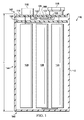
図1を参照して、典型的なバッテリーパック110が示される。バッテリーパック110は、ケース112、ターミナルプレート114、正のバッテリーパック・ターミナル116、負のバッテリーパック・ターミナル118、絶縁体120、インジケータ回路126、及び、少なくとも1つの電気化学セル128を含んでいる。インジケータ回路126は、アンテナ122、集積回路(IC)124、及び、通信回路160を含んでいる。ケース112は、閉鎖端140、開放端142、及び、その間のサイドウォール144を含んでいる。サイドウォール144は、高さHを有している。ターミナルプレート114は、ケース112の開放端142上方に載置される。インジケータ回路126は、ケース112のターミナルプレート114に取り付けられる。インジケータ回路126は、少なくとも1つの電気化学セル128と電気的に通信する。少なくとも1つの電気化学セル128は、正のバッテリーパック・ターミナル116及び負のバッテリーパック・ターミナル118と電気的に通信する。
With reference to FIG. 1, a
図2を参照して、典型的なバッテリーパック210が示される。バッテリーパック210は、ケース212、ターミナルプレート214、正のバッテリーパック・ターミナル216、負のバッテリーパック・ターミナル218、絶縁体220、インジケータ回路226、及び、少なくとも1つの電気化学セル228を含んでいる。インジケータ回路226は、アンテナ222、集積回路(IC)224、及び、通信回路260を含んでいる。ケース212は、閉鎖端240、開放端242、及び、その間のサイドウォール244を含んでいる。サイドウォール244は高さHを有している。ターミナルプレート214は、ケース212の開放端242上方に載置される。インジケータ回路226は、ケース212の閉鎖端240に取り付けられる。インジケータ回路226は、少なくとも1つの電気化学セル228と電気的に通信する。少なくとも1つの電気化学セル228は、正のバッテリーパック・ターミナル216及び負のバッテリーパック・ターミナル218と電気的に通信する。
With reference to FIG. 2, a
図3を参照して、典型的なバッテリーパック310が示される。バッテリーパック310は、ケース312、ターミナルプレート314、ベースプレート330、正のバッテリーパック・ターミナル316、負のバッテリーパック・ターミナル318、絶縁体320、インジケータ回路326、及び、少なくとも1つの電気化学セル328を含んでいる。インジケータ回路326は、アンテナ322、集積回路(IC)324、及び、通信回路360を含んでいる。ケース312は、第1の開放端346、第2の開放端348、及び、その間のサイドウォール344を含んでいる。サイドウォール344は、高さHを有している。ターミナルプレート314は、ケース312の第1の開放端346の上方に載置される。ベースプレート330はケース312の第2の開放端348の上方に載置される。インジケータ回路326は、ターミナルプレート314に取り付けられる。インジケータ回路326は、少なくとも1つの電気化学セル328と電気的に通信する。少なくとも1つの電気化学セル328は、正のバッテリーパック・ターミナル316及び負のバッテリーパック・ターミナル318と電気的に通信する。
With reference to FIG. 3, a
図4を参照して、典型的なバッテリーパック410が示される。バッテリーパック410は、ケース412、ターミナルプレート414、ベースプレート430、正のバッテリーパック・ターミナル416、負のバッテリーパック・ターミナル418、絶縁体420、インジケータ回路426、及び、少なくとも1つの電気化学セル428を含んでいる。インジケータ回路426は、アンテナ422、集積回路(IC)424、及び、通信回路460を含んでいる。ケース412は、第1の開放端446、第2の開放端448、及び、その間のサイドウォール444を含んでいる。サイドウォール444は、高さHを有している。ターミナルプレート414は、ケース412の第1の開放端446上方に載置される。ベースプレート430は、ケース412の第2の開放端448上方に載置される。インジケータ回路426は、ベースプレート430に取り付けられる。インジケータ回路426は、少なくとも1つの電気化学セル428と電気的に通信する。少なくとも1つの電気化学セル428は、正のバッテリーパック・ターミナル416及び負のバッテリーパック・ターミナル418と電気的に通信する。
Referring to FIG. 4, a
図5を参照して、典型的なバッテリーパック510が示される。バッテリーパック510は、ケース512、ターミナルプレート514、正のバッテリーパック・ターミナル516、負のバッテリーパック・ターミナル518、絶縁体520、磁気分流器550、インジケータ回路526、及び、少なくとも1つの電気化学セル528を含んでいる。インジケータ回路526は、アンテナ522及び集積回路(IC)524を含んでいる。ケース512は、閉鎖端540、開放端542、及び、その間のサイドウォール544を含んでいる。サイドウォール544は、高さHを有している。ターミナルプレート514は、ケース512の開放端542上方に載置される。集積回路524は、ターミナルプレート514に取り付けられる。アンテナ522は、ケース512に一体化されている。磁気分流器550は、少なくとも1つの電気化学セル528とアンテナ522の間のケース512のサイドウォールに、取り付けられる。インジケータ回路526は、少なくとも1つの電気化学セル528と電気的に通信する。少なくとも1つの電気化学セル528は、正のバッテリーパック・ターミナル516及び負のバッテリーパック・ターミナル518と電気的に通信する。
Referring to FIG. 5, a
図6を参照して、典型的なバッテリーパック610が示される。バッテリーパック610は、ケース612、ターミナルプレート614、正のバッテリーパック・ターミナル616、負のバッテリーパック・ターミナル618、絶縁体620、ベースプレート630、磁気分流器650、インジケータ回路626、及び、少なくとも1つの電気化学セル628を含んでいる。インジケータ回路626は、アンテナ622及び集積回路(IC)624を含んでいる。ケース612は、第1の開放端646、第2の開放端648、及び、その間のサイドウォール644を含んでいる。サイドウォール644は、高さHを有している。ターミナルプレート614は、ケース612の第1の開放端646上方に載置される。ベースプレート630は、ケース612の第2の開放端648上方に載置される。集積回路624は、ベースプレート630に取り付けられる。アンテナ622は、ケース612に一体化されている。磁気分流器650は、少なくとも1つの電気化学セル628とアンテナ622の間のケース612のサイドウォール644に、取り付けられる。インジケータ回路626は、少なくとも1つの電気化学セル628と電気的に通信する。少なくとも1つの電気化学セル628は、正のバッテリーパック・ターミナル616及び負のバッテリーパック・ターミナル618と電気的に通信する。
With reference to FIG. 6, a
図7を参照して、典型的なターミナルプレート714が示される。ターミナルプレート714は、正のバッテリーパック・ターミナル716、負のバッテリーパック・ターミナル718、及び、インジケータ回路726を含んでいる。インジケータ回路726は、アンテナ722、集積回路(IC)724、及び、通信回路760を含んでいる。インジケータ回路726は、正のバッテリーパック・ターミナル716及び負のバッテリーパック・ターミナル718と電気的に通信する。ターミナルプレート714がバッテリーパック内で使用される場合、正のバッテリーパック・ターミナル716及び負のバッテリーパック・ターミナル718は、少なくとも1つの電気化学セルと電気的に導通状態に置かれてもよい。
With reference to FIG. 7, a typical
図8を参照して、典型的なベースプレート830が示される。ベースプレート830は、インジケータ回路826を含んでいる。インジケータ回路826は、アンテナ822、集積回路(IC)824、及び、通信回路860を含んでいる。ベースプレート830がバッテリーパック内で使用される場合、インジケータ回路826は、正のバッテリーパック・ターミナル及び負のバッテリーパック・ターミナルと電気的に通信状態に置かれてもよい。
Referring to FIG. 8, a
図9を参照して、バッテリーパック910内の少なくとも1つの電気化学セルで占められているかもしれない典型的な容積が示される。バッテリーパック910は、ケース912、及び、少なくとも1つの電気化学セル928を含んでいる。少なくとも1つの電気化学セル928は、ケース912内の容積を占めており、容積はドットエリアによって表わされる。少なくとも1つの電気化学セル928によって占められる全容積は、全バッテリー容積と呼ばれるかもしれない。図9の中のバッテリーパック910の断面図は、例えば、バッテリーパック910内にある合計6つの電気化学セルのうちの3つの電気化学セルを示す。さらに、図9内の少なくとも1つの電気化学セル928は、円筒状セルとして示される。図9内の表現は例示的なものであり、バッテリーパック912内の少なくとも1つの電気化学セルの数、形或いはサイズについては、本発明を全く制限しないと認識されるべきである。
Referring to FIG. 9, a typical volume that may be occupied by at least one electrochemical cell in
図10を参照して、図9のバッテリーパック910内の典型的な内容積が示される。バッテリーパック910は、ケース912及びターミナルプレート914を含んでいる。ケース912は、閉鎖端940、開放端942、及び、その間のサイドウォール944を含んでいる。サイドウォール944は、高さHを有している。ターミナルプレート914は、ケース912の開放端942上方に載置される。バッテリーパックの内容積は、ケース912の開放端942上方に載置されるターミナルプレート914、ケース912のサイドウォール944、及び、ケース912の閉鎖端940によって、制限される空間として定義される。内容積は、ドットエリアによって表わされる。さらに、図10内のバッテリーパック910は、角柱状の、より具体的には、長方形の、バッテリーパックとして示されている。図10内の表現は例示的なものであり、バッテリーパック910の形或いはサイズについては、本発明を全く制限しないと認識されるべきである。
Referring to FIG. 10, a typical internal volume within the
図9及び図10を参照して、バッテリーパック910は、少なくとも1つの電気化学セル928によって占められた全容積を、バッテリーパック910の内容積で割り算したのと等しい、バッテリー対内容積の比率を有するだろう。
Referring to FIGS. 9 and 10, the
図11を参照して、バッテリーパック1110内の少なくとも1つの電気化学セルで占められているかもしれない典型的な容積が示される。バッテリーパック1110は、ケース1112及び少なくとも1つの電気化学セル1128を含んでいる。少なくとも1つの電気化学セル1128は、バッテリーパック1110内の容積を占める。容積はドットエリアによって表わされる。少なくとも1つの電気化学セル1128によって占められる全容積は、全バッテリー容積と呼ばれるかもしれない。バッテリーパック1110の断面図は、例えば、バッテリーパック1110内にある合計6つの電気化学セルのうちの3つの電気化学セルを示す。さらに、少なくとも1つの電気化学セル1128は、円筒状セルとして示される。図11内の表現は例示的なものであり、バッテリーパック1110内の少なくとも1つの電気化学セルの数、形或いはサイズについては、本発明を全く制限しないと認識されるべきである。
Referring to FIG. 11, a typical volume that may be occupied by at least one electrochemical cell in
図12を参照して、図11のバッテリーパック1110内の典型的な内容積が示される。バッテリーパック1110は、ケース1112、ターミナルプレート1114、及び、ベースプレート1130を含んでいる。ケース1112は、第1の開放端1146、第2の開放端1148、及び、それらの間のサイドウォール1144を含んでいる。サイドウォール1144は、高さHを有している。ターミナルプレート1114は、ケース1112の第1の開放端1146上方に載置される。ベースプレート1130は、ケース1112の第2の開放端1148上方に載置される。バッテリーパックの内容積は、ケース1112の第1の開放端1146上方に載置されるターミナルプレート1114、ケース1112の第2の開放端1148上方に載置されるベースプレート1130、及び、ケース1112のサイドウォール1144によって制限される空間として定義される。内容積は、ドットエリアによって表わされる。さらに、図12内のバッテリーパック1110は角柱状の、より具体的には、長方形の、バッテリーパックとして示されている。図12内の表現は例示的なものであり、バッテリーパック1110の形或いはサイズについては、本発明を全く制限しないと認識されるべきである。
Referring to FIG. 12, a typical internal volume within the
図11及び12を参照して、バッテリーパック1110は、少なくとも1つの電気化学セル1128によって占められた全容積を、バッテリーパック1110の内容積で割り算したのと等しい、バッテリー対内容積の比率を有するであろう。
Referring to FIGS. 11 and 12,
ここに示された寸法と値は、列挙された正確な数値に厳密に限定されると理解されない。代わりに、別段の定めがない限り、そのような寸法はそれぞれ、その値の前後の、列挙された値及び機能的に等価な領域の両方を意味することを意図している。例えば、「40mm」として示された寸法は、「約40mm」を意味することを意図している。 The dimensions and values shown herein are not to be understood as being strictly limited to the exact numerical values recited. Instead, unless otherwise specified, each such dimension is intended to mean both the recited value and a functionally equivalent area before and after that value. For example, a dimension indicated as “40 mm” is intended to mean “about 40 mm”.
明らかに除外され、或いは、他の方法で制限された場合を除き、ここに引用したすべての文献は、クロスで参照された若しくは関連付けられた特許若しくは出願、及び、本願の優先権若しくは利益を主張する特許出願若しくは特許を含め、参照によってその全体がここに組み入れられる。ここに開示した若しくはクレームした発明については、単独でも、そのような発明の他の参考文献、教示、示唆及び開示との組み合わせでも、先行技術として受け入れられない。さらに、参照により組み込まれた文献における同一文言の意味若しくは定義と抵触する本件書類の文言の意味若しくは定義の範囲は、本件書類において定義された文言の意味及び定義が支配される。 Except where expressly excluded or otherwise restricted, all references cited herein claim patents or applications cross-referenced or associated, and the priority or interest of this application. Including any patent applications or patents that are incorporated herein by reference in their entirety. The invention disclosed or claimed herein is unacceptable as prior art, either alone or in combination with other references, teachings, suggestions and disclosures of such invention. Further, the meaning or definition of the wording of this document that conflicts with the meaning or definition of the same wording in a document incorporated by reference is governed by the meaning and definition of the wording defined in this document.
本発明の特別の実施形態が図示され開示されたが、本発明の精神及び範囲から外れることなしに、様々な他の変更及び変更を行なえることは、当業者にとって明白だろう。したがって、添付のクレームにおいて、この発明の範囲内であるような変更及び修正を包含することを意図している。 While particular embodiments of the present invention have been illustrated and disclosed, it will be apparent to those skilled in the art that various other changes and modifications can be made without departing from the spirit and scope of the invention. Accordingly, it is intended by the appended claims to cover such changes and modifications as are within the scope of the invention.
Claims (9)
少なくとも1つの電気化学セルと、
ケースであって、第1の開放端、第2の開放端、およびその間のサイドウォールを備えるケースと、
前記第1の開放端の上方に載置されたターミナルプレート、および前記第2の開放端の上方に載置されたベースプレートと、
インジケータ回路であって、集積回路、及び、アンテナを備えるインジケータ回路と、 を備えており、
前記集積回路は、前記ベースプレートに取り付けられ、
前記バッテリーパックは、バッテリー対内容積の比率は、約0.52より大きい、
ことを特徴とする、バッテリーパック。 A battery pack,
At least one electrochemical cell Le,
A cases, and cases with the first open end, a second open end, and between the side walls,
A baseplate placed above the first open end upwardly placed on the terminal plates, and said second open end,
A indicator circuitry, integrated circuits, and provided with an indicator circuitry comprising antenna, a,
The integrated circuit is mounted on said base plate,
The battery pack has a battery to internal volume ratio greater than about 0.52 .
And wherein the battery pack.
Applications Claiming Priority (3)
| Application Number | Priority Date | Filing Date | Title |
|---|---|---|---|
| US14/469,776 US9893390B2 (en) | 2014-08-27 | 2014-08-27 | Battery pack including an indicator circuit |
| US14/469,776 | 2014-08-27 | ||
| PCT/US2015/045456 WO2016032783A1 (en) | 2014-08-27 | 2015-08-17 | Battery pack including an indicator circuit |
Publications (3)
| Publication Number | Publication Date |
|---|---|
| JP2017529658A JP2017529658A (en) | 2017-10-05 |
| JP2017529658A5 JP2017529658A5 (en) | 2018-09-06 |
| JP6408132B2 true JP6408132B2 (en) | 2018-10-17 |
Family
ID=53938465
Family Applications (1)
| Application Number | Title | Priority Date | Filing Date |
|---|---|---|---|
| JP2017509010A Active JP6408132B2 (en) | 2014-08-27 | 2015-08-17 | Battery pack including indicator circuit |
Country Status (7)
| Country | Link |
|---|---|
| US (1) | US9893390B2 (en) |
| EP (1) | EP3186843B1 (en) |
| JP (1) | JP6408132B2 (en) |
| CN (1) | CN106605314B (en) |
| AU (1) | AU2015307027B2 (en) |
| BR (1) | BR112017003125A2 (en) |
| WO (1) | WO2016032783A1 (en) |
Families Citing this family (15)
| Publication number | Priority date | Publication date | Assignee | Title |
|---|---|---|---|---|
| US9551758B2 (en) | 2012-12-27 | 2017-01-24 | Duracell U.S. Operations, Inc. | Remote sensing of remaining battery capacity using on-battery circuitry |
| US9478850B2 (en) | 2013-05-23 | 2016-10-25 | Duracell U.S. Operations, Inc. | Omni-directional antenna for a cylindrical body |
| US9726763B2 (en) | 2013-06-21 | 2017-08-08 | Duracell U.S. Operations, Inc. | Systems and methods for remotely determining a battery characteristic |
| US9882250B2 (en) | 2014-05-30 | 2018-01-30 | Duracell U.S. Operations, Inc. | Indicator circuit decoupled from a ground plane |
| WO2016025414A1 (en) | 2014-08-15 | 2016-02-18 | The Procter & Gamble Company | Oral care compositions and regimens |
| US10297875B2 (en) * | 2015-09-01 | 2019-05-21 | Duracell U.S. Operations, Inc. | Battery including an on-cell indicator |
| US10151802B2 (en) | 2016-11-01 | 2018-12-11 | Duracell U.S. Operations, Inc. | Reusable battery indicator with electrical lock and key |
| US10483634B2 (en) | 2016-11-01 | 2019-11-19 | Duracell U.S. Operations, Inc. | Positive battery terminal antenna ground plane |
| US10818979B2 (en) | 2016-11-01 | 2020-10-27 | Duracell U.S. Operations, Inc. | Single sided reusable battery indicator |
| US10608293B2 (en) | 2016-11-01 | 2020-03-31 | Duracell U.S. Operations, Inc. | Dual sided reusable battery indicator |
| US11024891B2 (en) | 2016-11-01 | 2021-06-01 | Duracell U.S. Operations, Inc. | Reusable battery indicator with lock and key mechanism |
| KR102410759B1 (en) * | 2016-11-07 | 2022-06-23 | 주식회사 엘지에너지솔루션 | Bluetooth antenna implemented on metal plate connecting battery cell |
| KR20210109018A (en) | 2019-01-09 | 2021-09-03 | 비와이디 컴퍼니 리미티드 | Battery packs and electric vehicles |
| FR3113748B1 (en) * | 2020-09-03 | 2023-08-11 | St Microelectronics Grenoble 2 | A method of storing instructions in program and associated system memory. |
| US11837754B2 (en) | 2020-12-30 | 2023-12-05 | Duracell U.S. Operations, Inc. | Magnetic battery cell connection mechanism |
Family Cites Families (9)
| Publication number | Priority date | Publication date | Assignee | Title |
|---|---|---|---|---|
| KR100599795B1 (en) * | 2004-06-29 | 2006-07-12 | 삼성에스디아이 주식회사 | Secondary battery |
| CN101385039B (en) * | 2006-03-15 | 2012-03-21 | 株式会社半导体能源研究所 | Semiconductor device |
| KR101023884B1 (en) * | 2009-02-18 | 2011-03-22 | 삼성에스디아이 주식회사 | Battery Pack |
| JP2012129183A (en) * | 2010-11-26 | 2012-07-05 | Sony Corp | Secondary battery cell, battery pack, and electricity consumption device |
| US9146595B2 (en) | 2011-08-05 | 2015-09-29 | Qualcomm Incorporated | Systems and methods for remotely monitoring or controlling a battery |
| JP5641006B2 (en) * | 2011-08-31 | 2014-12-17 | ソニー株式会社 | Power storage device |
| CN202308203U (en) * | 2011-11-04 | 2012-07-04 | 广州明美电子有限公司 | Serial lithium battery pack of light electric vehicle |
| US20130127611A1 (en) | 2011-11-20 | 2013-05-23 | Battery Marvel, Llc. | Battery marvel 1.0 |
| US9083063B2 (en) * | 2013-04-03 | 2015-07-14 | The Gillette Company | Electrochemical cell including an integrated circuit |
-
2014
- 2014-08-27 US US14/469,776 patent/US9893390B2/en active Active
-
2015
- 2015-08-17 AU AU2015307027A patent/AU2015307027B2/en active Active
- 2015-08-17 CN CN201580046285.5A patent/CN106605314B/en active Active
- 2015-08-17 WO PCT/US2015/045456 patent/WO2016032783A1/en active Application Filing
- 2015-08-17 BR BR112017003125A patent/BR112017003125A2/en not_active Application Discontinuation
- 2015-08-17 JP JP2017509010A patent/JP6408132B2/en active Active
- 2015-08-17 EP EP15753874.5A patent/EP3186843B1/en active Active
Also Published As
| Publication number | Publication date |
|---|---|
| US9893390B2 (en) | 2018-02-13 |
| AU2015307027A1 (en) | 2017-03-02 |
| US20160064781A1 (en) | 2016-03-03 |
| EP3186843A1 (en) | 2017-07-05 |
| JP2017529658A (en) | 2017-10-05 |
| AU2015307027B2 (en) | 2021-01-07 |
| EP3186843B1 (en) | 2018-12-26 |
| CN106605314B (en) | 2019-08-13 |
| WO2016032783A1 (en) | 2016-03-03 |
| CN106605314A (en) | 2017-04-26 |
| BR112017003125A2 (en) | 2017-11-28 |
Similar Documents
| Publication | Publication Date | Title |
|---|---|---|
| JP6408132B2 (en) | Battery pack including indicator circuit | |
| US10297875B2 (en) | Battery including an on-cell indicator | |
| JP6888053B2 (en) | Indicator circuit separated from the ground plane | |
| JP2018531479A6 (en) | Battery with on-cell indicator | |
| US11696942B2 (en) | Reusable battery indicator with electrical lock and key | |
| CN110165363B (en) | Omnidirectional antenna for cylindrical bodies |
Legal Events
| Date | Code | Title | Description |
|---|---|---|---|
| A521 | Request for written amendment filed |
Free format text: JAPANESE INTERMEDIATE CODE: A523 Effective date: 20180724 |
|
| A621 | Written request for application examination |
Free format text: JAPANESE INTERMEDIATE CODE: A621 Effective date: 20180724 |
|
| A871 | Explanation of circumstances concerning accelerated examination |
Free format text: JAPANESE INTERMEDIATE CODE: A871 Effective date: 20180724 |
|
| A975 | Report on accelerated examination |
Free format text: JAPANESE INTERMEDIATE CODE: A971005 Effective date: 20180809 |
|
| TRDD | Decision of grant or rejection written | ||
| A01 | Written decision to grant a patent or to grant a registration (utility model) |
Free format text: JAPANESE INTERMEDIATE CODE: A01 Effective date: 20180821 |
|
| A61 | First payment of annual fees (during grant procedure) |
Free format text: JAPANESE INTERMEDIATE CODE: A61 Effective date: 20180919 |
|
| R150 | Certificate of patent or registration of utility model |
Ref document number: 6408132 Country of ref document: JP Free format text: JAPANESE INTERMEDIATE CODE: R150 |
|
| R250 | Receipt of annual fees |
Free format text: JAPANESE INTERMEDIATE CODE: R250 |
|
| R250 | Receipt of annual fees |
Free format text: JAPANESE INTERMEDIATE CODE: R250 |
|
| R250 | Receipt of annual fees |
Free format text: JAPANESE INTERMEDIATE CODE: R250 |