JP6406830B2 - Cutting device, packaging bag manufacturing device, and packaging bag manufacturing method - Google Patents
Cutting device, packaging bag manufacturing device, and packaging bag manufacturing method Download PDFInfo
- Publication number
- JP6406830B2 JP6406830B2 JP2014027658A JP2014027658A JP6406830B2 JP 6406830 B2 JP6406830 B2 JP 6406830B2 JP 2014027658 A JP2014027658 A JP 2014027658A JP 2014027658 A JP2014027658 A JP 2014027658A JP 6406830 B2 JP6406830 B2 JP 6406830B2
- Authority
- JP
- Japan
- Prior art keywords
- packaging bag
- cutting device
- cutting
- continuous package
- blade
- Prior art date
- Legal status (The legal status is an assumption and is not a legal conclusion. Google has not performed a legal analysis and makes no representation as to the accuracy of the status listed.)
- Active
Links
Images


Landscapes
- Auxiliary Devices For And Details Of Packaging Control (AREA)
Description
本発明は、連続包装体を包装袋ごとに切断する切断装置と、これを用いた包装袋の製造装置、および包装袋の製造方法に関する。 The present invention relates to a cutting device that cuts a continuous package for each packaging bag, a packaging bag manufacturing apparatus using the cutting device, and a packaging bag manufacturing method.
従来、液体や粉体等の内容物を充填した包装袋を製造する装置としては、フィルム等の包材を縦横にシールして袋状に形成し、内容物を充填後に包装袋をシール(密封)した後、包装袋ごとに切断する充填包装装置が知られている。 Conventionally, as a device for manufacturing packaging bags filled with contents such as liquids and powders, a packaging material such as a film is sealed vertically and horizontally to form a bag, and after filling the contents, the packaging bag is sealed (sealed) ), And then a filling and packaging device that cuts each packaging bag is known.
特許文献1には、カッタが、可動刃部を有する雄型カッタと、筒状ケース内に配置された固定刃部を有する雌型カッタとを備えて構成され、可動刃部は予備包装体を挿通するための凹部を形成するとともに、凹部の両側部が傾斜して形成され、筒状ケースには固定刃部における可動刃部と反対の側にスクラップの収納部が形成された包装体製造装置が記載されている。 In Patent Document 1, the cutter is configured to include a male cutter having a movable blade portion and a female cutter having a fixed blade portion disposed in a cylindrical case, and the movable blade portion is a spare packaging body. A packaging body manufacturing apparatus in which a concave portion for insertion is formed, both side portions of the concave portion are formed to be inclined, and the cylindrical case has a scrap storage portion formed on the side opposite to the movable blade portion in the fixed blade portion Is described.
特許文献2には、雄刃ブロックは、切断動作の移動で帯状材をセンタリングするガイド部を有し、雌刃ブロックは、雌刃の両端より外側で雄刃ブロックのガイド部を案内するガイド穴を有し、雄刃ブロックのガイド部と雌刃ブロックのガイド穴とが切断待機中も常時嵌合状態に組み合わされる打ち抜き切断刃が記載されている。 In Patent Document 2, the male blade block has a guide portion for centering the belt-like material by movement of the cutting operation, and the female blade block is a guide hole for guiding the guide portion of the male blade block outside both ends of the female blade. A punching cutting blade is described in which the guide portion of the male blade block and the guide hole of the female blade block are always combined in a fitted state even during standby for cutting.
特許文献1に記載された発明の場合、可動側のカッタにテーパ状のガイドを設けていることから、固定刃部に対して可動刃部が移動するストローク量に応じてテーパの角度を小さくする必要がある。このため、可動側部品は、寸法が大きく、また構造が複雑になる。
特許文献2に記載された発明の場合、ガイド部が常時嵌め合い状態で組み合わさっていることから、構成部品の形状が複雑になる。
In the case of the invention described in Patent Literature 1, since the guide on the movable side is provided with a tapered guide, the taper angle is reduced according to the stroke amount that the movable blade moves relative to the fixed blade. There is a need. For this reason, the movable part has a large size and a complicated structure.
In the case of the invention described in Patent Document 2, since the guide portions are always combined in a fitted state, the shape of the component parts becomes complicated.
本発明は、上記事情に鑑みてなされたものであり、部品の構造を簡潔にし、切断箇所の位置ズレの抑制や切り屑の排出を容易にすることが可能な切断装置と、これを用いた包装袋の製造装置、および包装袋の製造方法を提供することを課題とする。 The present invention has been made in view of the above circumstances, and uses a cutting device capable of simplifying the structure of a part, suppressing the displacement of a cut portion and facilitating the discharge of chips, and the like. It is an object of the present invention to provide a packaging bag manufacturing apparatus and a packaging bag manufacturing method.
前記課題を解決するため、本発明は、長手方向に複数の包装袋が連続して形成された連続包装体を、包装袋ごとに切断する切断装置であって、前記包装袋は、長手方向の両側にそれぞれ一端部と他端部とを有し、前記連続包装体において隣接する包装袋の前記一端部と前記他端部との間には、切断時に除去される除去部が設けられ、前記切断装置は、前記一端部と前記他端部を切断する雄刃部を有する雄刃ユニットと、前記雄刃部と嵌合する雌刃部を有する雌刃ユニットとを備え、前記雄刃ユニットは、前記雄刃部において前記一端部を切断する刃型と前記他端部を切断する刃型との間から前記連続包装体に向けて気体を噴出する吹き出し口を有し、前記雌刃ユニットは、前記連続包装体の幅方向両側を前記雌刃部に向けて案内するガイド部と、前記雌刃部の裏側から前記除去部を排出する排出穴とを有し、前記連続包装体の前記除去部が前記切断装置により切断される前に、前記吹き出し口から前記連続包装体に向けて気体を噴出することにより、前記連続包装体を押圧して、前記連続包装体の幅方向両側を前記ガイド部により前記雌刃部に向けて案内することを特徴とする切断装置を提供する。 In order to solve the above-mentioned problem, the present invention provides a cutting device for cutting a continuous package in which a plurality of packaging bags are continuously formed in the longitudinal direction for each packaging bag, Each side has an end portion and the other end portion, and between the one end portion and the other end portion of the adjacent packaging bags in the continuous package, a removal portion to be removed at the time of cutting is provided, The cutting device includes a male blade unit having a male blade portion for cutting the one end portion and the other end portion, and a female blade unit having a female blade portion fitted to the male blade portion, The male blade portion has a blowout port for blowing gas toward the continuous package from between a blade mold for cutting the one end portion and a blade mold for cutting the other end portion, and the female blade unit is And a guide portion for guiding both sides in the width direction of the continuous package toward the female blade portion. , Possess a discharge hole for discharging the removed portion from the back side of the female blade portion, prior to the removal portion of the continuous package is cut by the cutting device, directed to the continuous package from the outlet The cutting apparatus is characterized in that the continuous package is pressed by blowing the gas to guide both sides of the continuous package in the width direction toward the female blade by the guide .
前記ガイド部は、前記連続包装体の幅方向両側にそれぞれガイド斜面を有し、前記ガイド斜面の間隔は、前記雌刃部に対する前記雄刃部の挿入方向において、前記雌刃部に近づくほど間隔が狭くなることが好ましい。 The guide part has guide slopes on both sides in the width direction of the continuous package, and the guide slopes are spaced closer to the female blade part in the insertion direction of the male blade part with respect to the female blade part. Is preferably narrow .
前記連続包装体の前記除去部が前記切断装置により切断された後に、前記吹き出し口から前記連続包装体に向けて気体を噴出することにより、前記除去部の切り屑を前記排出穴から排出することが好ましい。
前記雄刃部および前記雌刃部が前記包装袋を切断する形状は、前記一端部または前記他端部の少なくとも一方に曲線を含むことが好ましい。
After the removal portion of the continuous package is cut by the cutting device, the chips of the removal portion are discharged from the discharge hole by ejecting gas from the outlet toward the continuous package. Is preferred.
The shape in which the male blade portion and the female blade portion cut the packaging bag preferably includes a curve in at least one of the one end portion or the other end portion.
また、本発明は、長手方向に複数の包装袋が連続して形成された連続包装体を、包装袋ごとに切断して包装袋を製造する包装袋の製造装置であって、前記連続包装体を包装袋ごとに切断するため、前記切断装置を備えることを特徴とする包装袋の製造装置を提供する。 Further, the present invention is a packaging bag manufacturing apparatus for manufacturing a packaging bag by cutting a continuous packaging body in which a plurality of packaging bags are continuously formed in a longitudinal direction for each packaging bag, the continuous packaging body In order to cut | disconnect a bag for every packaging bag, the manufacturing apparatus of the packaging bag provided with the said cutting device is provided.
また、本発明は、長手方向に複数の包装袋が連続して形成された連続包装体を、包装袋ごとに切断して包装袋を製造する包装袋の製造方法であって、前記連続包装体を包装袋ごとに切断するため、前記切断装置を用いることを特徴とする包装袋の製造方法を提供する。 The present invention also relates to a method for manufacturing a packaging bag, in which a continuous packaging body in which a plurality of packaging bags are continuously formed in the longitudinal direction is cut for each packaging bag to produce a packaging bag. In order to cut | disconnect a bag for every packaging bag, the manufacturing method of the packaging bag characterized by using the said cutting device is provided.
本発明によれば、連続包装体の除去部が切断装置により切断される前に、吹き出し口から連続包装体に向けて気体を噴出することにより、連続包装体を押圧して、連続包装体の幅方向両側をガイド部により雌刃部に向けて案内することができる。また、本発明によれば、連続包装体の除去部が切断装置により切断された後に、吹き出し口から連続包装体に向けて気体を噴出することにより、除去部の切り屑を排出穴から排出することができる。 According to the present invention, before the removal portion of the continuous packaging body is cut by the cutting device, the continuous packaging body is pressed by blowing gas toward the continuous packaging body from the outlet, Both sides in the width direction can be guided toward the female blade portion by the guide portion. Moreover, according to this invention, after the removal part of a continuous packaging body is cut | disconnected by the cutting device, the chip of a removal part is discharged | emitted from a discharge hole by ejecting gas toward a continuous packaging body from a blower outlet. be able to.
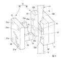
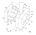
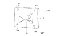
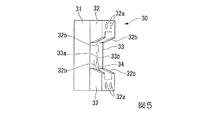
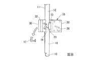
以下、好適な実施形態に基づき、図面を参照して本発明を説明する。図1および図2に、本発明の実施例の切断装置10の使用状況を例示する。図1は、切断装置10を雄刃ユニット20の側から見た斜視図である。図2は、切断装置10を雌刃ユニット30の側から見た斜視図である。図3は、雄刃ユニット20を雄刃部23の側から見た斜視図である。図4は、雌刃ユニット30を、排出穴35の開口側(裏面側)から見た斜視図である。図5は、雌刃ユニット30を、雌刃部34の側から見た斜視図である。図6は、雄刃ユニット20と雌刃ユニット30を組み合わせた切断装置10の斜視図である。図7は、切断装置10により連続包装体11を切断する前の状況を示す斜視図である。図8は、切断装置10により連続包装体11を切断した後の状況を示す斜視図である。
Hereinafter, based on a preferred embodiment, the present invention will be described with reference to the drawings. FIG. 1 and FIG. 2 illustrate the usage situation of the
図1および図6に示すように、切断装置10は、雄刃部23を有する雄刃ユニット20と、雌刃部34を有する雌刃ユニット30とを対向させた構成を備え、長手方向に複数の包装袋12,12が連続して形成された連続包装体11を、包装袋12,12ごとに切断する装置である。切断時には、雄刃部23が雌刃部34に挿入され、両者が嵌合する。雄刃部23と雌刃部34の形状および寸法の関係は、公知の切断装置と同様でよい。
As shown in FIGS. 1 and 6, the
図7に示すように、包装袋12は、長手方向の両側にそれぞれ一端部13と他端部14とを有する。図示例では、一端部13はタブやノッチ等を有する開封部であり、他端部14は底部である。連続包装体11において隣接する包装袋12,12の一端部13と他端部14との間には、切断時に除去される除去部15が設けられている。
As shown in FIG. 7, the
図1および図2に示すように、雄刃ユニット20の雄刃部23は、一端部13を切断する刃型23aと、他端部14を切断する刃型23bを有する。雄刃部23は、略矩形状の基部21の片側に突出する突出部22の先端に設けられている。基部21には、雄刃ユニット20を不図示の駆動部に固定するためのネジ等の取付けに使用可能な複数の固定穴21aを有する。該駆動部は、雄刃ユニット20を雌刃ユニット30に対向する前後方向に往復移動させる手段である。図示例では、固定された雌刃ユニット30に対し、雄刃ユニット20は可動である。
As shown in FIGS. 1 and 2, the
雄刃部23の先端面24は、刃型23a,23bの間において、基部21と略平行で、雄刃ユニット20の往復移動方向に略垂直な平面である。先端面24には、連続包装体11に向けて気体を噴出する吹き出し口25,25を有する。図示例では、二箇所の吹き出し口25,25が先端面24の左右に分かれて配置されている。吹き出し口25,25に気体を供給するため、基部21の裏面(図1参照)には、気体供給部26が設けられている。図示例の気体供給部26は吹き出し口25,25の裏側に通じた溝である。気体は空気(エア)でもよく、他の気体でもよい。
The
図5に示すように、雌刃部34は、雌刃ユニット30の基部31に形成された貫通穴に形成されている。基部31は、雌刃ユニット30を不図示の治具に固定するためのネジ等の取付けに使用可能な複数の固定穴31aを有する。図2および図4に示すように、基部31の裏面には、雌刃部34の裏側から除去部15を排出する排出穴35を有する。図示例の場合、排出穴35の形状は、雌刃部34の形状と同一である。
As shown in FIG. 5, the
図5に示すように、雌刃ユニット30の基部31の表面における雌刃部34の周囲には、雄刃ユニット20の往復移動方向に対して連続包装体11を受けることが可能な受け部33と、連続包装体11の幅方向両側を雌刃部34に向けて案内するガイド部32,32が設けられている。受け部33は、包装袋12の一端部13に対応する受け部33aと、包装袋12の他端部14に対応する受け部33bを含む。
As shown in FIG. 5, around the
ガイド部32,32は、連続包装体11の幅方向両側にそれぞれガイド斜面32b,32bを有する。ガイド斜面32b,32bの間隔(図5の上下方向の寸法)は、雌刃部34に対する雄刃部23の挿入方向において、雌刃部34に近づくほど、狭くなっている。ガイド部32には、ガイド部32を基部31に固定するためのネジ等の取付けに使用可能な複数の固定穴32aを有する。
The
連続包装体11の切断前には、図7に示すように、雌刃ユニット30のガイド部32,32の間に連続包装体11が配置される。切断前に、雄刃ユニット20の吹き出し口25から連続包装体11に向けて気体を噴出することにより、連続包装体11が雌刃ユニット30の受け部33に向けて押圧される。ガイド部32,32は、連続包装体11の幅方向の両側縁に向けてガイド斜面32b,32bを有するので、連続包装体11がガイド斜面32b,32bに沿って移動することにより、幅方向中央に寄せられ、雌刃部34に向けて位置決めされる。
Before the
次に、雄刃ユニット20と雌刃ユニット30とが互いに近づくように、一方または両方のユニットを移動させる。図示例では、雌刃ユニット30に対して雄刃ユニット20を移動させる。雄刃部23を雌刃部34に挿入し、両者を嵌合させる間に、連続包装体11の除去部15が切断され、連続包装体11の先頭(下端)で包装袋16が分離される。図8は、切断後、さらに雌刃ユニット30から雄刃ユニット20を引き離した状態を示す。切断の前後では、雄刃ユニット20と雌刃ユニット30とが互いに接触しないように、引き離すことも可能である。
Next, one or both units are moved so that the
除去部15が切断された後に、雄刃ユニット20の吹き出し口25から連続包装体11に向けて気体を噴出すると、除去部15の切り屑17が押圧され、切り屑17が雌刃部34の貫通穴を通過して、排出穴35から排出される。雌刃ユニット30の裏側には、排出穴35から排出される切り屑17の回収を容易にするため、トンネル状、ホース状、漏斗状などの回収手段(図示せず)を設けることが好ましい。
After the
本実施形態の切断装置10は、包装袋の製造装置(図示せず)に組み込むことが可能である。包装袋の製造装置は、連続包装体の長手方向に沿う縦シールを行う縦シール手段、連続包装体の長手方向に交差した方向に横シールを行う横シール手段、連続包装体の内部に内容物を充填する充填手段を備えてもよい。本実施形態において、上述の除去部15は、横シールである。横シールは、内容物の充填前でもよく、内容物の充填後(液中シール)でもよい。包装袋のシール構成は、三方シール、四方シール、背貼りシール等が一般的である。長手方向に複数の包装袋が連続して形成された連続包装体を製造した後、連続包装体を包装袋ごとに切断することで、包装袋を製造することができる。
The cutting
雄刃部23および雌刃部34が包装袋12を切断する形状は、一端部13または他端部14の少なくとも一方に曲線を含むことが好ましい。図示例では、一端部13はタブの周縁等に円弧などの曲線を含み、他端部14は底部両端のコーナー(隅部)に円弧を含む。包装袋12の形状は、幅方向に比べて長手方向が数倍長いスティック状である。
The shape in which the
連続包装体11がガイド部32,32により位置決めされた状態で、切断装置10が除去部15を切断し、包装袋12の一端部13と他端部14を加工するので、包装袋12の位置ズレがなくなり、コーナーのRの大きさにばらつきがなくなる。包装袋12の周囲を封止するシール部の幅は、包装袋の周縁と、包装袋の内部に内容物を充填するスペースとの距離によって決まるので、一端部13および他端部14において包装袋12の周縁の形状が正確に加工されることにより、シール部の幅のばらつきが抑制され、確実な封止が容易になる。従来は、シール部の幅のばらつきを考慮して、設計上のシール部の幅を大きめに確保していたが、寸法が大きくなったり、デザインの自由度が低下したりする問題があった。本実施形態によれば、一端部13および他端部14の形状が複雑でも、切断装置10の構造を複雑にすることなく、必要なシール部の幅を確保することができる。
Since the cutting
連続包装体の位置決めや切り屑の排出に際して、気体を噴出して加圧する手法は、吸引を行う場合に比べると、装置の構造がより単純になる。また、気体を噴出する時間を短時間に制限することも容易にできるので、連続包装体が振動したり、ゴミが装置に付着したりする等のトラブルを回避または抑制することができる。 When positioning the continuous package or discharging chips, the method of jetting and pressurizing the gas makes the structure of the device simpler than when performing suction. In addition, since the time for ejecting the gas can be easily limited to a short time, troubles such as vibration of the continuous package and adhesion of dust to the apparatus can be avoided or suppressed.
以上、本発明を好適な実施形態に基づいて説明してきたが、本発明は上述の実施形態に限定されるものではなく、本発明の要旨を逸脱しない範囲で種々の改変が可能である。 As mentioned above, although this invention has been demonstrated based on suitable embodiment, this invention is not limited to the above-mentioned embodiment, A various change is possible in the range which does not deviate from the summary of this invention.
上述の実施形態においては、雄刃部において、包装袋の一端部を切断する刃型と、包装袋の他端部を切断する刃型との間は、包装袋の幅方向全長にわたり一定以上(間に平面が形成される程度)の間隔を有している。しかし、本発明は、この場合に限定されず、一端部を切断する刃型と他端部を切断する刃型とが、包装袋の幅方向の一部において接続し、刃型の一部が線状になってもよい。 In the above-described embodiment, in the male blade portion, the distance between the blade mold that cuts one end of the packaging bag and the blade mold that cuts the other end of the packaging bag is equal to or greater than the entire length in the width direction of the packaging bag ( The interval is such that a plane is formed between them. However, the present invention is not limited to this case, and the blade mold that cuts one end and the blade mold that cuts the other end are connected in a part in the width direction of the packaging bag, and a part of the blade mold is It may be linear.
連続包装体を構成するフィルムとしては、シーラントを少なくとも片面に備える積層体、例えば、ポリエチレン(PE)、ポリプロピレン(PP)、エチレン―酢酸ビニル共重合体(EVA)、環状ポリオレフィンなどのポリオレフィン樹脂層を最内層(シーラント)とし、二軸延伸ナイロンフィルムや二軸延伸ポリエチレンテレフタレートフィルム、二軸延伸ポリプロピレンフィルムなどの延伸フィルムを基材とし、必要に応じてエチレン―ビニルアルコール共重合体、金属や無機化合物の蒸着層(アルミ蒸着など)、アルミ箔等の金属箔、インキ層等の印刷層などを中間層としたラミネートフィルムを用いることができるが、特に、これらに限定されるものでない。積層フィルムを製造する方法としては、ドライラミネート法、押出ラミネート法、共押出法などが挙げられる。基材層とシーラント層との間には接着強度の向上のため、接着剤やアンカー剤等を設けることができる。包装袋の強度を高めるため、積層フィルム中に基材層を複数枚積層してもよい。 As a film constituting the continuous package, a laminate having a sealant on at least one side, for example, a polyolefin resin layer such as polyethylene (PE), polypropylene (PP), ethylene-vinyl acetate copolymer (EVA), and cyclic polyolefin is used. The innermost layer (sealant) is made of a stretched film such as a biaxially stretched nylon film, a biaxially stretched polyethylene terephthalate film or a biaxially stretched polypropylene film, and an ethylene-vinyl alcohol copolymer, metal or inorganic compound as required. A laminate film having an intermediate layer of a vapor deposition layer (aluminum vapor deposition, etc.), a metal foil such as an aluminum foil, or a printing layer such as an ink layer can be used, but is not particularly limited thereto. Examples of the method for producing the laminated film include a dry laminating method, an extrusion laminating method, and a coextrusion method. An adhesive, an anchor agent, or the like can be provided between the base material layer and the sealant layer in order to improve the adhesive strength. In order to increase the strength of the packaging bag, a plurality of base material layers may be laminated in the laminated film.
10…切断装置、11…連続包装体、12…包装袋、13…一端部、14…他端部、15…除去部、16…切断後の包装袋、17…切り屑、20…雄刃ユニット、21…基部、21a…固定穴、22…突出部、23…雄刃部、23a,23b…刃型、24…先端面、25…吹き出し口、26…気体供給部、30…雌刃ユニット、31…基部、31a…固定穴、32…ガイド部、32a…固定穴、32b…ガイド斜面、33,33a,33b…受け部、34…雌刃部、35…排出穴。
DESCRIPTION OF
Claims (6)
前記包装袋は、長手方向の両側にそれぞれ一端部と他端部とを有し、前記連続包装体において隣接する包装袋の前記一端部と前記他端部との間には、切断時に除去される除去部が設けられ、
前記切断装置は、前記一端部と前記他端部を切断する雄刃部を有する雄刃ユニットと、前記雄刃部と嵌合する雌刃部を有する雌刃ユニットとを備え、
前記雄刃ユニットは、前記雄刃部において前記一端部を切断する刃型と前記他端部を切断する刃型との間から前記連続包装体に向けて気体を噴出する吹き出し口を有し、
前記雌刃ユニットは、前記連続包装体の幅方向両側を前記雌刃部に向けて案内するガイド部と、前記雌刃部の裏側から前記除去部を排出する排出穴とを有し、
前記連続包装体の前記除去部が前記切断装置により切断される前に、前記吹き出し口から前記連続包装体に向けて気体を噴出することにより、前記連続包装体を押圧して、前記連続包装体の幅方向両側を前記ガイド部により前記雌刃部に向けて案内することを特徴とする切断装置。 A cutting device for cutting a continuous package in which a plurality of packaging bags are continuously formed in the longitudinal direction for each packaging bag,
The packaging bag has one end and the other end on both sides in the longitudinal direction, and is removed when cutting between the one end and the other end of the adjacent packaging bags in the continuous package. A removal section is provided,
The cutting device includes a male blade unit having a male blade portion that cuts the one end portion and the other end portion, and a female blade unit having a female blade portion that fits the male blade portion,
The male blade unit has a blowout port for blowing gas toward the continuous package from between a blade mold for cutting the one end portion and a blade mold for cutting the other end portion in the male blade portion,
It said female blade unit may possess a guide portion for guiding the widthwise sides of the continuous package toward the female blade portion, and a discharge hole for discharging the removed portion from the back side of the female blade portion,
Before the removal part of the continuous package is cut by the cutting device, the continuous package is pressed by blowing gas toward the continuous package from the outlet, and the continuous package A cutting device characterized by guiding both sides in the width direction toward the female blade portion by the guide portion .
前記連続包装体を包装袋ごとに切断するため、請求項1〜4のいずれか1項に記載の切断装置を備えることを特徴とする包装袋の製造装置。 A packaging bag manufacturing apparatus for manufacturing a packaging bag by cutting a continuous packaging body in which a plurality of packaging bags are continuously formed in a longitudinal direction for each packaging bag,
In order to cut | disconnect the said continuous package for every packaging bag, the cutting device of any one of Claims 1-4 is provided, The manufacturing apparatus of the packaging bag characterized by the above-mentioned.
前記連続包装体を包装袋ごとに切断するため、請求項1〜4のいずれか1項に記載の切断装置を用いることを特徴とする包装袋の製造方法。 A packaging bag manufacturing method for manufacturing a packaging bag by cutting a continuous packaging body in which a plurality of packaging bags are continuously formed in a longitudinal direction for each packaging bag,
In order to cut | disconnect the said continuous package body for every packaging bag, the manufacturing method of the packaging bag characterized by using the cutting device of any one of Claims 1-4 .
Priority Applications (1)
| Application Number | Priority Date | Filing Date | Title |
|---|---|---|---|
| JP2014027658A JP6406830B2 (en) | 2014-02-17 | 2014-02-17 | Cutting device, packaging bag manufacturing device, and packaging bag manufacturing method |
Applications Claiming Priority (1)
| Application Number | Priority Date | Filing Date | Title |
|---|---|---|---|
| JP2014027658A JP6406830B2 (en) | 2014-02-17 | 2014-02-17 | Cutting device, packaging bag manufacturing device, and packaging bag manufacturing method |
Publications (2)
| Publication Number | Publication Date |
|---|---|
| JP2015151172A JP2015151172A (en) | 2015-08-24 |
| JP6406830B2 true JP6406830B2 (en) | 2018-10-17 |
Family
ID=53893845
Family Applications (1)
| Application Number | Title | Priority Date | Filing Date |
|---|---|---|---|
| JP2014027658A Active JP6406830B2 (en) | 2014-02-17 | 2014-02-17 | Cutting device, packaging bag manufacturing device, and packaging bag manufacturing method |
Country Status (1)
| Country | Link |
|---|---|
| JP (1) | JP6406830B2 (en) |
Families Citing this family (2)
| Publication number | Priority date | Publication date | Assignee | Title |
|---|---|---|---|---|
| CN116409511B (en) * | 2023-05-24 | 2025-05-20 | 美赞臣营养品(香港)有限公司 | A bagged product cutting and finishing line |
| CN117381873A (en) * | 2023-10-18 | 2024-01-12 | 楚天科技股份有限公司 | A solid strip bag slitting device capable of cutting easy-tear seams |
Family Cites Families (4)
| Publication number | Priority date | Publication date | Assignee | Title |
|---|---|---|---|---|
| JPH0755466B2 (en) * | 1986-12-01 | 1995-06-14 | 株式会社興人 | Sheet cutting mechanism |
| JPH04365597A (en) * | 1991-06-13 | 1992-12-17 | Uchiyama Kikai Seisakusho:Kk | Punching device for sheet-form material |
| JP4564378B2 (en) * | 2004-12-27 | 2010-10-20 | 三光機械株式会社 | R-cutter device for vertical multi-row automatic packaging machine |
| JP4919880B2 (en) * | 2007-06-11 | 2012-04-18 | 兼房株式会社 | Strip cutting tool |
-
2014
- 2014-02-17 JP JP2014027658A patent/JP6406830B2/en active Active
Also Published As
| Publication number | Publication date |
|---|---|
| JP2015151172A (en) | 2015-08-24 |
Similar Documents
| Publication | Publication Date | Title |
|---|---|---|
| JP5647384B2 (en) | Packaging bag cutting apparatus, method and manufacturing apparatus therefor | |
| US10717577B2 (en) | Plastic bag making apparatus | |
| KR101923407B1 (en) | My waiting | |
| JP5319987B2 (en) | Zipper tape and packaging bag with zipper tape | |
| US20200247066A1 (en) | Ultrasonic sealing anvil and ultrasonic sealing apparatus | |
| JPWO2017057244A1 (en) | Anvil and ultrasonic sealing device | |
| JP6892817B2 (en) | Gazette bag with spout | |
| CN107000919B (en) | Assembly of external container and liquid container, its manufacturing method and liquid container | |
| JP2019038584A (en) | Packaging container forming and filling device | |
| JP6406830B2 (en) | Cutting device, packaging bag manufacturing device, and packaging bag manufacturing method | |
| JP7498639B2 (en) | Apparatus for punching and joining film pieces, apparatus for manufacturing film, apparatus for manufacturing bag-shaped containers, method for punching and joining film pieces, method for manufacturing film, and method for manufacturing bag-shaped containers | |
| WO2018028450A1 (en) | Liquid transport system, liner bag and method of use | |
| JP2002224994A (en) | Processing device for plastic bag | |
| JP2013039932A (en) | Packaging bag with spout | |
| JP4642600B2 (en) | Packaging bag with spout | |
| KR102301095B1 (en) | Apparatus for manufacturing infusion container | |
| JP2009090987A (en) | Self-supporting packaging bag | |
| JP4614294B2 (en) | bag | |
| JP2020006495A (en) | Film cutting method and cutting device | |
| JP2015016018A (en) | Fitting tool and bag with fitting tool | |
| EP1609731B1 (en) | Method of manufacturing self-supportable bag | |
| JP6881305B2 (en) | Ultrasonic sealing device | |
| KR101712881B1 (en) | Self-standing type package | |
| JP2008162611A (en) | Composite container and manufacturing method thereof | |
| JP2019050096A (en) | Manufacturing method of bipolar electrode and manufacturing device for bipolar electrode |
Legal Events
| Date | Code | Title | Description |
|---|---|---|---|
| A621 | Written request for application examination |
Free format text: JAPANESE INTERMEDIATE CODE: A621 Effective date: 20170126 |
|
| A131 | Notification of reasons for refusal |
Free format text: JAPANESE INTERMEDIATE CODE: A131 Effective date: 20180220 |
|
| A521 | Request for written amendment filed |
Free format text: JAPANESE INTERMEDIATE CODE: A523 Effective date: 20180409 |
|
| TRDD | Decision of grant or rejection written | ||
| A01 | Written decision to grant a patent or to grant a registration (utility model) |
Free format text: JAPANESE INTERMEDIATE CODE: A01 Effective date: 20180821 |
|
| A61 | First payment of annual fees (during grant procedure) |
Free format text: JAPANESE INTERMEDIATE CODE: A61 Effective date: 20180918 |
|
| R150 | Certificate of patent or registration of utility model |
Ref document number: 6406830 Country of ref document: JP Free format text: JAPANESE INTERMEDIATE CODE: R150 |
|
| R250 | Receipt of annual fees |
Free format text: JAPANESE INTERMEDIATE CODE: R250 |
|
| R250 | Receipt of annual fees |
Free format text: JAPANESE INTERMEDIATE CODE: R250 |
|
| R250 | Receipt of annual fees |
Free format text: JAPANESE INTERMEDIATE CODE: R250 |