JP6405802B2 - Air cleaner - Google Patents

Air cleaner Download PDF

Info

Publication number
JP6405802B2
JP6405802B2 JP2014178066A JP2014178066A JP6405802B2 JP 6405802 B2 JP6405802 B2 JP 6405802B2 JP 2014178066 A JP2014178066 A JP 2014178066A JP 2014178066 A JP2014178066 A JP 2014178066A JP 6405802 B2 JP6405802 B2 JP 6405802B2
Authority
JP
Japan
Prior art keywords
deodorizing filter
air
unit
deodorizing
filter
Prior art date
Legal status (The legal status is an assumption and is not a legal conclusion. Google has not performed a legal analysis and makes no representation as to the accuracy of the status listed.)
Active
Application number
JP2014178066A
Other languages
Japanese (ja)
Other versions
JP2016049402A (en
Inventor
裕二 中矢
裕二 中矢
喜内 一彰
一彰 喜内
克弘 大野
克弘 大野
Current Assignee (The listed assignees may be inaccurate. Google has not performed a legal analysis and makes no representation or warranty as to the accuracy of the list.)
Fujitsu General Ltd
Original Assignee
Fujitsu General Ltd
Priority date (The priority date is an assumption and is not a legal conclusion. Google has not performed a legal analysis and makes no representation as to the accuracy of the date listed.)
Filing date
Publication date
Application filed by Fujitsu General Ltd filed Critical Fujitsu General Ltd
Priority to JP2014178066A priority Critical patent/JP6405802B2/en
Publication of JP2016049402A publication Critical patent/JP2016049402A/en
Application granted granted Critical
Publication of JP6405802B2 publication Critical patent/JP6405802B2/en
Active legal-status Critical Current
Anticipated expiration legal-status Critical

Links

Images

Description

本発明は、加熱により脱臭能力が再生できる脱臭ユニットを備えた空気清浄機に関する。   The present invention relates to an air cleaner provided with a deodorizing unit that can regenerate the deodorizing ability by heating.

従来、空気清浄機として、本体筐体内に設けられた送風機の駆動によって本体筐体内に吸い込んだ空気を脱臭フィルタに通過させて空気に含まれる臭気成分を吸着させ、脱臭フィルタを加熱して脱臭能力を再生するものが提案されている。そして、このような空気清浄機のなかには、脱臭フィルタが回転可能に設けられるとともに、脱臭フィルタと接触せずにその一部を覆うように配置される加熱部を備えた空気清浄機がある(例えば、特許文献1参照)。   Conventionally, as an air purifier, the air sucked into the main body casing by driving the blower provided in the main body casing is passed through the deodorizing filter to adsorb the odor components contained in the air, and the deodorizing filter is heated to deodorize it. Something to play is proposed. Among such air purifiers, there is an air purifier that is provided with a heating unit that is disposed so as to cover a part of the deodorizing filter without being in contact with the deodorizing filter (for example, , See Patent Document 1).

特許文献1に記載の空気清浄機は、空気吸込口から本体筐体内に吸い込んだ空気を空気吹出口へ導く空気流路を有し、空気吸込口から空気吹出口へ向かう方向に順に、プレフィルタ、触媒構造体、送風ファンが配置されている。触媒構造体は、空気中の臭気成分を吸着する円板状の吸着板(脱臭フィルタに相当)と、空気流路の上壁にブラケットによって固定されるとともに、出力軸が吸着板の中心部に接続されて吸着板を回転駆動するモータと、吸着板の一部を覆うカバーとで構成されている。このカバーは、吸着板の前面の一部および背面の一部を覆っており、カバーの前面側および背面側の各々の内壁面には、臭気成分を分解する触媒板と、吸着板および触媒板を加熱する発熱体(加熱部に相当)が設けられている。   The air cleaner described in Patent Document 1 has an air flow path that guides air sucked into the main body housing from the air suction port to the air blowout port, and in order in the direction from the air suction port to the air blowout port, the prefilter The catalyst structure and the blower fan are arranged. The catalyst structure is fixed to a disk-like adsorption plate (equivalent to a deodorization filter) that adsorbs odor components in the air and a bracket on the upper wall of the air flow path, and the output shaft is located at the center of the adsorption plate. The motor includes a motor that is connected to rotate the suction plate and a cover that covers a part of the suction plate. The cover covers a part of the front surface and a part of the back surface of the adsorption plate. A catalyst plate for decomposing odor components, an adsorption plate and a catalyst plate are provided on each of the inner wall surfaces on the front side and the back side of the cover. Is provided with a heating element (corresponding to a heating section).

この空気清浄機で送風ファンを駆動すると、空気吸込口から空気流路に吸い込まれた空気は、プレフィルタで空気に含まれる塵埃が除去されて吸着板に達し、吸着板のカバーから露出した部分を通過する際に臭気成分が吸着される。このようにして清浄された空気は、空気吹出口から再び室内に吹き出される。一方、カバーに覆われた吸着板の一部は発熱体によって加熱され、当該箇所に吸着されていた臭気成分は吸着板から脱離する。脱離した臭気成分は、同じく発熱体によって加熱された触媒板によって分解される。尚、吸着板はモータによって一定時間毎に所定角度(例えば、90度)ずつ回転させる。   When the blower fan is driven by this air cleaner, the air sucked into the air flow path from the air suction port is removed from the dust contained in the air by the pre-filter and reaches the suction plate, and is exposed from the cover of the suction plate. Odor components are adsorbed when passing through. The air purified in this way is blown out into the room again from the air outlet. On the other hand, a part of the adsorption plate covered with the cover is heated by the heating element, and the odor component adsorbed on the part is desorbed from the adsorption plate. The detached odor component is decomposed by the catalyst plate heated by the heating element. The suction plate is rotated by a predetermined angle (for example, 90 degrees) by a motor every predetermined time.

上述した空気清浄機では、カバーで覆われた吸着板の一部を発熱体によって加熱して脱臭能力を再生するとともに、カバーから露出している吸着板で空気の脱臭を行えるので、吸着板の形状に対応して形成された発熱体で一度に吸着板全体を加熱する場合に比べて消費電力が少ない。また、吸着板の一部のみがカバーで覆われる構造であるため、吸着板の形状に対応して形成された発熱体を設ける場合と比べて脱臭フィルタの空気抵抗が小さい。   In the above-described air purifier, a part of the adsorption plate covered with the cover is heated by a heating element to regenerate the deodorization ability, and the deodorization ability of the adsorption plate exposed from the cover can be removed. Less power is consumed than when the entire suction plate is heated at once with a heating element corresponding to the shape. In addition, since only a part of the adsorption plate is covered with the cover, the air resistance of the deodorizing filter is smaller than when a heating element formed corresponding to the shape of the adsorption plate is provided.

特開平10−277365号公報Japanese Patent Laid-Open No. 10-277365

特許文献1に記載の空気清浄機では、上述したように、吸着板を回転させるモータがブラケットによって空気流路に固定されるとともに、モータの出力軸に吸着板の中心部が接合されている。つまり、吸着板は片持ち(モータの出力軸1点で)固定されている。このような固定方法では、モータの出力軸に吸着板を接合する際に吸着板が出力軸に対して直交せずに傾いた状態で接合された場合や、ブラケットや出力軸に変形が生じた場合に、モータによって吸着板が回転したときに吸着板がカバーに接触し、吸着板が回転しないあるいは吸着板が損傷する、といった問題が発生する虞があった。   In the air cleaner described in Patent Document 1, as described above, the motor that rotates the suction plate is fixed to the air flow path by the bracket, and the center portion of the suction plate is joined to the output shaft of the motor. That is, the suction plate is cantilevered (at one point on the motor output shaft). With such a fixing method, when the suction plate is joined to the output shaft of the motor, if the suction plate is joined without being orthogonal to the output shaft, the bracket or the output shaft is deformed. In some cases, when the suction plate is rotated by the motor, the suction plate comes into contact with the cover, which may cause a problem that the suction plate does not rotate or the suction plate is damaged.

本発明は以上述べた問題点を解決し、脱臭フィルタを損傷させることなく確実に回転させて、脱臭フィルタの脱臭能力の再生が行える空気清浄機を提供することを目的とする。   An object of the present invention is to solve the above-described problems and to provide an air cleaner that can reliably rotate the deodorizing filter without damaging it and regenerate the deodorizing ability of the deodorizing filter.

本発明は上述の課題を解決するものであって、本発明の空気清浄機は、筐体内に空気を取り込む空気吸込口と、筐体内から外部へ空気を放出する空気吹出口と、空気吸込口と空気吹出口とを連通させる通風路とを有し、通風路内に、送風機と、送風機の駆動により通風路内に取り込まれた空気を脱臭する脱臭ユニットとが配置されたものであって、脱臭ユニットは、円板形状に形成されて中心部に貫通孔を設けた脱臭フィルタと、脱臭フィルタの一部を覆うように配置されて脱臭フィルタの一部を加熱する加熱部と、脱臭フィルタ及び加熱部を保持する保持部と、を有する。また、脱臭フィルタ全体を加熱部で加熱するために、加熱部を固定するとともに脱臭フィルタを回転させる、あるいは、脱臭フィルタを固定するとともに加熱部を脱臭フィルタの外周部に沿って回転させる駆動部と、駆動部によって脱臭フィルタあるいは加熱部が回転するとき、脱臭フィルタと加熱部とが接触しないように脱臭フィルタを支える複数の支持部材とを有する。そして、支持部材は、筒部と、同筒部の両端に設けられた上フランジと下フランジとを備えるとともに、脱臭フィルタの厚み方向への可動範囲を上フランジと下フランジにより規制することで脱臭フィルタを支える。さらに、支持部材は、少なくとも脱臭フィルタの内周部を支える第1支持部材と、脱臭フィルタの外周部を支える第2支持部材とを有する。 The present invention solves the above-mentioned problems, and an air cleaner according to the present invention includes an air suction port for taking air into the housing, an air outlet for discharging air from the housing to the outside, and an air suction port. And a ventilation path that communicates with the air outlet, and a blower and a deodorizing unit that deodorizes the air taken into the ventilation path by driving the blower are disposed in the ventilation path, The deodorizing unit includes a deodorizing filter formed in a disk shape and provided with a through hole in the center, a heating unit that is disposed so as to cover a part of the deodorizing filter, and heats a part of the deodorizing filter, A holding unit that holds the heating unit . In addition, in order to heat the entire deodorizing filter with the heating unit, the driving unit that fixes the heating unit and rotates the deodorizing filter, or that fixes the deodorizing filter and rotates the heating unit along the outer periphery of the deodorizing filter; When the deodorizing filter or the heating unit is rotated by the drive unit, the deodorizing filter and the heating unit are provided with a plurality of support members that support the deodorizing filter so that the deodorizing filter and the heating unit do not contact each other. The support member includes a cylindrical portion, and an upper flange and a lower flange provided at both ends of the cylindrical portion, and deodorizes by restricting the movable range in the thickness direction of the deodorizing filter by the upper flange and the lower flange. Support the filter. Further, the support member includes at least a first support member that supports the inner peripheral portion of the deodorizing filter and a second support member that supports the outer peripheral portion of the deodorizing filter.

本発明の空気清浄機は、脱臭フィルタの中心部に貫通孔を設け、この貫通孔の内周部と脱臭フィルタの外周部とで脱臭フィルタを支持することで、加熱部と脱臭フィルタとの距離を一定に保つ。従って、脱臭フィルタあるいは加熱部を回転させるときに、脱臭フィルタと加熱部とが接触して回転しないといった問題や、脱臭フィルタが加熱部に接触して損傷するといった問題が発生しない。   The air cleaner of the present invention has a through hole in the center of the deodorizing filter, and the deodorizing filter is supported by the inner periphery of the through hole and the outer periphery of the deodorizing filter, so that the distance between the heating unit and the deodorizing filter is increased. Keep constant. Therefore, when rotating a deodorizing filter or a heating part, the problem that a deodorizing filter and a heating part contact and do not rotate, and the problem that a deodorizing filter contacts a heating part do not generate | occur | produce.

本発明の実施形態における、空気清浄機の外観斜視図である。It is an appearance perspective view of an air cleaner in an embodiment of the present invention. 本発明の実施形態における、空気清浄機の上面図である。It is a top view of an air cleaner in an embodiment of the present invention. 図1におけるX−X断面図である。It is XX sectional drawing in FIG. 図1におけるY−Y断面図である。It is YY sectional drawing in FIG. 本発明の実施形態における要部斜視図であり、脱臭ユニットの配置説明図である。It is a principal part perspective view in embodiment of this invention, and is arrangement | positioning explanatory drawing of a deodorizing unit. 本発明の実施形態における、脱臭ユニットの分解図である。It is an exploded view of the deodorizing unit in the embodiment of the present invention. 本発明の実施形態における、加熱部の分解図である。It is an exploded view of a heating part in an embodiment of the present invention. 脱臭フィルタと加熱部との位置関係を示す概略図であり、(A)は図6の要部Mを真横から見た概略図、(B)は要部Nを真横から見た概略図である。It is the schematic which shows the positional relationship of a deodorizing filter and a heating part, (A) is the schematic which looked at the principal part M of FIG. 6 from right side, (B) is the schematic which looked at the principal part N from right side. .

以下、本発明の実施の形態を、添付図面に基づいて詳細に説明する。尚、本発明は以下の実施形態に限定されることはなく、本発明の主旨を逸脱しない範囲で種々変形することが可能である。   Embodiments of the present invention will be described below in detail with reference to the accompanying drawings. The present invention is not limited to the following embodiments, and can be variously modified without departing from the gist of the present invention.

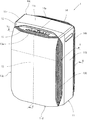
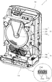
図1および図2に示すように、本発明の一実施形態である空気清浄機1は、各々合成樹脂材で成形された天面パネル11a、右側面パネル11b、左側面パネル11c、底部11dで略直方体状に形成された本体部11を有し、本体部11の一方の面に合成樹脂材で成形された前面パネル12が配置され、他方の面に合成樹脂材で成形されたリアパネル14が配置されている。尚、以降の説明において、必要に応じ本体部11の前面パネル12配置側を本体部前面側、本体部11のリアパネル14配置側を本体部背面側と称する。   As shown in FIGS. 1 and 2, an air cleaner 1 according to an embodiment of the present invention includes a top panel 11a, a right side panel 11b, a left side panel 11c, and a bottom part 11d, each molded with a synthetic resin material. A front panel 12 formed of a synthetic resin material is disposed on one surface of the main body portion 11 and a rear panel 14 formed of a synthetic resin material is disposed on the other surface. Has been placed. In the following description, the front panel 12 arrangement side of the main body 11 is referred to as the main body front side, and the rear panel 14 arrangement side of the main body 11 is referred to as the main body rear side as necessary.

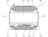
前面パネル12の前方には、合成樹脂材で成形されたフロントパネル13が配置され、このフロントパネル13と前面パネル12との間に、本発明の空気吸込口である上面吸込口13a、右側面吸込口13b、および左側面吸込口13cが形成される。また、本体部11とリアパネル14との間に、本発明の空気吹出口である上面吹出口14a、右側面吹出口14b、および左側面吹出口14cが形成される。空気清浄機1では、上面吸込口13a、右側面吸込口13b、および左側面吸込口13cから本体部11に吸い込んだ空気を、上面吹出口14a、右側面吹出口14b、および左側面吹出口14cから室内に吹き出す間に、空気の除塵・加湿および脱臭処理が行われるようになっている。
尚、図3および図4に示すように、上面吸込口13a、右側面吸込口13b、および左側面吸込口13cと、上面吹出口14a、右側面吹出口14b、および左側面吹出口14cとを連通する本体部11内部の空間が、本発明の空気清浄機1における通風路10となる。
A front panel 13 formed of a synthetic resin material is disposed in front of the front panel 12, and an upper surface suction port 13a that is an air suction port of the present invention, a right side surface is provided between the front panel 13 and the front panel 12. A suction port 13b and a left side suction port 13c are formed. Moreover, between the main-body part 11 and the rear panel 14, the upper surface outlet 14a which is the air outlet of this invention, the right side outlet 14b, and the left side outlet 14c are formed. In the air cleaner 1, the air sucked into the main body 11 from the upper surface inlet 13 a, the right side inlet 13 b, and the left side inlet 13 c is the upper surface outlet 14 a, right side outlet 14 b, and left side outlet 14 c. The air is dedusted / humidified and deodorized while being blown into the room.
As shown in FIGS. 3 and 4, the upper surface inlet 13a, the right side inlet 13b, and the left side inlet 13c, and the upper surface outlet 14a, the right side outlet 14b, and the left side outlet 14c are provided. The space inside the main body 11 that communicates becomes the ventilation path 10 in the air cleaner 1 of the present invention.

空気清浄機1の上面部には、上面吸込口13aの一部を覆うように操作部15が設けられている。操作部15は、電源ボタンや運転モード切り換えボタン等の空気清浄機1を操作するボタンが配置されるとともに、空気清浄機1の運転状態や図示しない塵埃センサ等の検出器における検出結果を表示する表示部が配置されている。   An operation unit 15 is provided on the upper surface portion of the air cleaner 1 so as to cover a part of the upper surface suction port 13a. The operation unit 15 is provided with buttons for operating the air purifier 1 such as a power button and an operation mode switching button, and displays the operation state of the air purifier 1 and detection results in a detector such as a dust sensor (not shown). A display unit is arranged.

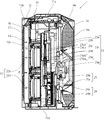
図3に示すように、空気清浄機1の本体部11内部の通風路10には、上面吸込口13a、右側面吸込口13b、および左側面吸込口13cから上面吹出口14a、右側面吹出口14b、および左側面吹出口14cに向かって順に、プレフィルタ21、集塵ユニット22、脱臭ユニット23、加湿ユニット24、送風機25が配置されている。   As shown in FIG. 3, the air passage 10 inside the main body portion 11 of the air cleaner 1 has an upper surface outlet 14 a and a right side outlet from the upper surface inlet 13 a, the right side inlet 13 b, and the left side inlet 13 c. The prefilter 21, the dust collection unit 22, the deodorizing unit 23, the humidification unit 24, and the air blower 25 are arrange | positioned in order toward 14b and the left side surface outlet 14c.

プレフィルタ21は、例えば糸状のPET材を編みこんで網目構造としたものであり、本体部11内部に吸い込まれる空気に含まれる塵埃を捕集する。図4に示すように、プレフィルタ21は、本体部前面側に向かって凸となるようなアーチ形状に形成されているので、プレフィルタ21を平坦な形状とする場合と比べて、上面吸込口13a、右側面吸込口13b、および左側面吸込口13cから本体部11内部に吸い込まれた空気がプレフィルタ21を通過する面積が大きくなるので、より多くの塵埃を捕集することができる。   The prefilter 21 has a mesh structure formed by weaving, for example, a thread-like PET material, and collects dust contained in the air sucked into the main body 11. As shown in FIG. 4, the prefilter 21 is formed in an arch shape that is convex toward the front side of the main body, and therefore the upper surface suction port compared to the case where the prefilter 21 is flat. 13a, the area through which the air sucked into the main body 11 from the right side suction port 13b and the left side suction port 13c passes through the prefilter 21 is increased, so that more dust can be collected.

図3に示すように、集塵ユニット22は、第1電気集塵機22aと第2電気集塵機22bとで構成されている。第1電気集塵機22aと第2電気集塵機22bとは、本体部11の前面側に配置され本体部11の一部を構成する仕切板16に上下方向に並べて配置されている。第1電気集塵機22aおよび第2電気集塵機22bは、図示しない放電電極と集塵電極とを有し、放電電極によるコロナ放電によりプレフィルタ21で捕集できなかった細かな塵埃や花粉等を帯電させ、帯電した塵埃や花粉等を集塵電極で捕集する。第1電気集塵機22aおよび第2電気集塵機22bは、主に上述した放電電極や集塵電極、および、これらを保持する筐体で形成されているので、集塵ユニット22の空気抵抗は、例えば不織布をプリーツ形状に形成してなる集塵フィルタの空気抵抗に比べて小さい。   As shown in FIG. 3, the dust collection unit 22 includes a first electric dust collector 22a and a second electric dust collector 22b. The first electrostatic precipitator 22a and the second electrostatic precipitator 22b are arranged side by side in the vertical direction on the partition plate 16 that is arranged on the front side of the main body 11 and constitutes a part of the main body 11. The first electrostatic precipitator 22a and the second electrostatic precipitator 22b have a discharge electrode and a dust collection electrode (not shown), and charge fine dust or pollen that could not be collected by the prefilter 21 due to corona discharge by the discharge electrode. Then, charged dust or pollen is collected by the dust collecting electrode. Since the first electrostatic precipitator 22a and the second electrostatic precipitator 22b are mainly formed by the above-described discharge electrode and dust collector, and a housing that holds them, the air resistance of the dust collector 22 is, for example, a non-woven fabric. Is smaller than the air resistance of a dust collection filter formed in a pleated shape.

図3乃至図5に示すように、脱臭ユニット23は、脱臭フィルタ23aと加熱手段である加熱部23fと保持部23gとを有する。図5に示すように、脱臭フィルタ23aは、例えば、平板材と、この平板材を波形に形成した屈曲材とを交互に積層してなる波形構造や、ハニカム構造のような多孔構造の基材を円板形状に形成したもので、その基材23aaに臭気成分を吸着して分解する触媒層23abが設けられている。図5に示すように、加熱部23fは、脱臭フィルタ23aの一部のみを覆う略三角柱形状に形成されている。図3および図4に示すように、加熱部23fは、発熱体としてのPTCヒータ23bと、前面側放熱板23caと背面側放熱板23cbとからなる放熱板23cと、2個の断熱材23dと、前面側ケース23eaと背面側ケース23ebとからなるケース23eとで構成される。保持部23gは、脱臭フィルタ23aと加熱部23fとを保持するものであり、通風路10における集塵ユニット22の背面側に固定される。このように、脱臭フィルタ23aは多孔構造を有しており、また、加熱部23fが脱臭フィルタ23aの一部のみ覆う構造となっているので、脱臭フィルタ23aの空気抵抗は小さい。
尚、脱臭ユニット23の構造については、後に図6乃至図8を用いて詳細に説明する。
As shown in FIGS. 3 to 5, the deodorizing unit 23 includes a deodorizing filter 23a, a heating unit 23f that is a heating unit, and a holding unit 23g. As shown in FIG. 5, the deodorizing filter 23a includes, for example, a corrugated structure formed by alternately laminating a flat plate material and a bending material formed by corrugating the flat plate material, or a porous structure base material such as a honeycomb structure. Is formed in a disk shape, and a catalyst layer 23ab for adsorbing and decomposing odorous components is provided on the base material 23aa. As shown in FIG. 5, the heating part 23f is formed in a substantially triangular prism shape that covers only a part of the deodorizing filter 23a. As shown in FIGS. 3 and 4, the heating unit 23f includes a PTC heater 23b as a heating element, a heat radiating plate 23c including a front side heat radiating plate 23ca and a back side heat radiating plate 23cb, and two heat insulating materials 23d. The case 23e is composed of a front case 23ea and a back case 23eb. The holding part 23g holds the deodorizing filter 23a and the heating part 23f, and is fixed to the back side of the dust collection unit 22 in the ventilation path 10. Thus, the deodorizing filter 23a has a porous structure, and since the heating unit 23f has a structure that covers only a part of the deodorizing filter 23a, the air resistance of the deodorizing filter 23a is small.
The structure of the deodorizing unit 23 will be described in detail later with reference to FIGS.

図3乃至図5に示すように、加湿ユニット24は、加湿フィルタ24aと水を貯留する貯水タンク24bとを有する。加湿フィルタ24aは、円板形状に形成されてその一部が貯水タンク24bに溜められた水に浸った状態で回転軸により回転可能に支持されており、図示しないモータにより回転するようになっている。尚、加湿ユニット24は上記に限らず、回転によって水分を吸い上げる加湿フィルタ24aに代えて、毛細管現象によって水分を吸い上げる加湿フィルタであってもよい。また、図5においては、脱臭ユニット23や加湿ユニット24が視認しやすいようにするために、フロントパネル13や底部11d以外の本体部11を構成する部材、集塵ユニット22等の描画を適宜省略している。   As shown in FIGS. 3 to 5, the humidification unit 24 includes a humidification filter 24a and a water storage tank 24b for storing water. The humidifying filter 24a is formed in a disk shape, and a part of the humidifying filter 24a is rotatably supported by a rotating shaft in a state where the humidifying filter 24a is immersed in water stored in the water storage tank 24b, and is rotated by a motor (not shown). Yes. The humidifying unit 24 is not limited to the above, and may be a humidifying filter that sucks moisture by capillary action instead of the humidifying filter 24a that sucks moisture by rotation. Further, in FIG. 5, drawing of the members constituting the main body 11 other than the front panel 13 and the bottom 11d, the dust collecting unit 22 and the like is appropriately omitted so that the deodorizing unit 23 and the humidifying unit 24 can be easily seen. doing.

図3および図4に示すように、送風機25は、ターボファン25aとファンモータ25bとを有する。ターボファン25aは、合成樹脂材で形成されており、ファンモータ25bの出力軸に接続されている。ファンモータ25bは回転数可変であり、ファンモータ25bが回転することでターボファン25aも回転し、ターボファン25aの回転によって、空気清浄機1内部へ空気が流入あるいは空気清浄機1内部から空気が流出する。   As shown in FIGS. 3 and 4, the blower 25 includes a turbo fan 25a and a fan motor 25b. The turbo fan 25a is made of a synthetic resin material and is connected to the output shaft of the fan motor 25b. The fan motor 25b has a variable number of rotations, and the fan motor 25b rotates, so that the turbo fan 25a also rotates. By the rotation of the turbo fan 25a, air flows into the air purifier 1 or air flows from the air purifier 1 into the air. leak.

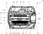
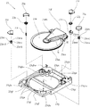
次に、図6乃至図8を用いて、本実施形態における脱臭ユニット23の詳細構造について説明する。図6に示すように、脱臭ユニット23は前述した脱臭フィルタ23aと加熱部23fと保持部23gとに加えて、駆動部23hと、駆動歯車23jと、第2歯車23kと、2個のローラ23mと、4枚の押さえ部材23zと、回転検出部23rとを有する。また、図7に示すように、加熱部23fは、前述したPTCヒータ23bと2枚の断熱材23dとに加えて、放熱板23cを構成する第1放熱板である前面側放熱板23caおよび第2放熱板である背面側放熱板23cbと、ケース23eを構成する前面側ケース23eaおよび背面側ケース23ebと、ヒータケース23pと、本発明の支持部材である3個のローラ23nとを有する。そして、脱臭フィルタ23aは、前述した基材23aaおよび触媒層23abに加えて、外周部に設けられた第1歯車23acと中心部に設けられた貫通孔である中心孔23adと中心孔23adを覆う覆い部23aeとを有する。図8(B)に示すように、第1歯車23acの厚さ寸法T1は、フィルタ本体の厚さ寸法T2より大きくされている(例えば、T2−T1=3mm)。尚、図示は省略するが、覆い部23aeの厚さ寸法も第1歯車23acと同じT1とされている。また、脱臭フィルタ23aは、その一部を覆うように加熱部23fが取り付けられる。   Next, the detailed structure of the deodorizing unit 23 in this embodiment is demonstrated using FIG. 6 thru | or FIG. As shown in FIG. 6, in addition to the deodorizing filter 23a, the heating unit 23f, and the holding unit 23g, the deodorizing unit 23 includes a driving unit 23h, a driving gear 23j, a second gear 23k, and two rollers 23m. And four pressing members 23z and a rotation detector 23r. Further, as shown in FIG. 7, in addition to the PTC heater 23b and the two heat insulating materials 23d, the heating unit 23f includes a front side heat radiating plate 23ca and a first heat radiating plate constituting the heat radiating plate 23c. It includes a rear side heat radiating plate 23cb which is a two heat radiating plate, a front side case 23ea and a rear side case 23eb constituting the case 23e, a heater case 23p, and three rollers 23n which are support members of the present invention. In addition to the base material 23aa and the catalyst layer 23ab, the deodorizing filter 23a covers the first gear 23ac provided in the outer peripheral portion and the central hole 23ad and the central hole 23ad that are through holes provided in the central portion. And a cover portion 23ae. As shown in FIG. 8B, the thickness dimension T1 of the first gear 23ac is larger than the thickness dimension T2 of the filter body (for example, T2−T1 = 3 mm). In addition, although illustration is abbreviate | omitted, the thickness dimension of the cover part 23ae is also set to T1 same as the 1st gearwheel 23ac. Moreover, the heating part 23f is attached so that the deodorizing filter 23a may cover a part.

まず、図7を用いて加熱部23fを構成する部材および加熱部23fの組み立て方法について説明する。前面側放熱板23caは、熱伝導性の良好なアルミニウム材またはアルミ合金材を用いて形成されており、脱臭フィルタ23aの前面側に配置されて脱臭フィルタ23aの貫通孔23adから外周側に向かうにつれて左右方向(脱臭フィルタ23aの円周方向)の幅寸法が大きくなるような略三角形状に形成されている。また、前面側放熱板23caの一方の面が脱臭フィルタ23aに対向するフィルタ対向面23caaとされ、他方の面が後述するPTCヒータ23bおよびヒータケース23pが配置されるヒータ配置面23cabとされている。   First, the member which comprises the heating part 23f, and the assembly method of the heating part 23f are demonstrated using FIG. The front-side heat radiating plate 23ca is formed using an aluminum material or an aluminum alloy material having good thermal conductivity. The front-side heat radiating plate 23ca is disposed on the front side of the deodorizing filter 23a and goes from the through hole 23ad of the deodorizing filter 23a toward the outer peripheral side. It is formed in a substantially triangular shape so that the width dimension in the left-right direction (circumferential direction of the deodorizing filter 23a) increases. Also, one surface of the front side heat radiating plate 23ca is a filter facing surface 23caa that faces the deodorizing filter 23a, and the other surface is a heater placement surface 23cab on which a PTC heater 23b and a heater case 23p described later are placed. .

背面側放熱板23cbは、熱伝導性の良好なアルミニウム材またはアルミ合金材を用いて形成されており、前面側放熱板23caと同じく脱臭フィルタ23aの背面側に配置されて脱臭フィルタ23aの貫通孔23adから外周側に向かうにつれて左右方向(脱臭フィルタ23aの円周方向)の幅寸法が大きくなるような略三角形状に形成されている。背面側放熱板23cbは、本体部23ccと、前面側放熱板23caに接してPTCヒータ23bで発生し前面側放熱板23caを伝わる熱を本体部23ccに伝える第1接合部23cdおよび第2接合部23ceとを有している。本体部23ccは、略三角形状に形成され、一方の面が脱臭フィルタ23aに対向するフィルタ対向面23ccaとされ、他方の面が断熱材23dが配置される断熱材配置面23ccbとされている。第1接合部23cdは、本体部23ccの脱臭フィルタ23aにおける外周側の側縁部を略L字状に折り曲げて形成され、前面側放熱板23caに接合する面が第1接合面23cdaとされている。第2接合部23ceは、本体部23ccの脱臭フィルタ23aにおける内周側の側縁部を略L字状に折り曲げて形成され、前面側放熱板23caに接合する面が第1接合面23cdaとされている。尚、本体部23ccのフィルタ対向面23ccaと、第1接合部23cdの第1接合面23cdaおよび第2接合部23ceの第2接合面23ceaとの間の高さ寸法Hは、脱臭フィルタ23aの第1歯車23acの厚さ寸法T1より大きい寸法とされている。   The rear side heat radiating plate 23cb is formed using an aluminum material or an aluminum alloy material having good thermal conductivity, and is disposed on the rear side of the deodorizing filter 23a in the same manner as the front side heat radiating plate 23ca, and is a through hole of the deodorizing filter 23a. The width dimension in the left-right direction (circumferential direction of the deodorizing filter 23a) increases from 23ad toward the outer peripheral side. The rear side heat radiating plate 23cb is in contact with the main body portion 23cc and the first joint portion 23cd and the second joint portion that are in contact with the front side heat radiating plate 23ca and transmit heat generated in the PTC heater 23b to the front side heat radiating plate 23ca to the main body portion 23cc. 23ce. The main body portion 23cc is formed in a substantially triangular shape, and one surface is a filter facing surface 23cca facing the deodorizing filter 23a, and the other surface is a heat insulating material disposing surface 23ccb on which the heat insulating material 23d is disposed. The first joint portion 23cd is formed by bending an outer peripheral side edge portion of the deodorizing filter 23a of the main body portion 23cc into a substantially L shape, and a surface joined to the front side heat radiating plate 23ca is a first joint surface 23cda. Yes. The second joint portion 23ce is formed by bending an inner peripheral side edge of the deodorizing filter 23a of the main body portion 23cc into a substantially L shape, and a surface joined to the front side heat radiating plate 23ca is a first joint surface 23cda. ing. The height dimension H between the filter facing surface 23cca of the main body portion 23cc and the first joint surface 23cda of the first joint portion 23cd and the second joint surface 23cea of the second joint portion 23ce is the same as that of the deodorizing filter 23a. It is a dimension larger than the thickness dimension T1 of one gear 23ac.

2枚の断熱材23dは、発泡ウレタン材を用いて前面側放熱板23caの形状および背面側放熱板23cbの形状に応じた略三角形状に形成されている。ヒータケース23pは、板金を用いて有底直方体形状に形成されている。ヒータケース23pはPTCヒータ23bを収納できる形状とされており、前面側放熱板23caの脱臭フィルタ23aに対向する面であるフィルタ対向面23caaに固定できるようになっている。   The two heat insulating materials 23d are formed in a substantially triangular shape according to the shape of the front side heat radiating plate 23ca and the shape of the rear side heat radiating plate 23cb using a urethane foam material. The heater case 23p is formed in a bottomed rectangular parallelepiped shape using sheet metal. The heater case 23p is configured to accommodate the PTC heater 23b, and can be fixed to the filter facing surface 23caa, which is the surface facing the deodorizing filter 23a of the front side heat radiating plate 23ca.

3個のローラ23nは、合成樹脂材を用いて形成されており、筒部23nbと、上フランジ23ncと、下フランジ23ndとを有している。筒部23nbは円筒形状に形成され、後述する前面側ケース23eaに設けられた第3軸23qの形状に応じた孔23naが設けられている。上フランジ23ncと下フランジ23ndとは、筒部23nbの両端に設けられており、各々筒部23nbより大きい直径の円板形状に形成されている。上フランジ23ncと下フランジ23ndとの間の寸法Sは、脱臭フィルタ23aの厚さ寸法Tよりも大きい寸法とされている。尚、図7に示すように、ローラ23nは、第1支持部材である1個の内側ローラ23niと、第2支持部材である2個の外側ローラ23noとからなり、これら内側ローラ23niと外側ローラ23noとは同じ形状である。   The three rollers 23n are formed using a synthetic resin material, and have a cylindrical portion 23nb, an upper flange 23nc, and a lower flange 23nd. The cylindrical portion 23nb is formed in a cylindrical shape, and is provided with a hole 23na corresponding to the shape of the third shaft 23q provided in the front side case 23ea described later. The upper flange 23nc and the lower flange 23nd are provided at both ends of the cylindrical portion 23nb, and are each formed in a disk shape having a larger diameter than the cylindrical portion 23nb. A dimension S between the upper flange 23nc and the lower flange 23nd is larger than the thickness dimension T of the deodorizing filter 23a. As shown in FIG. 7, the roller 23n includes one inner roller 23ni that is a first support member and two outer rollers 23no that are second support members. The inner roller 23ni and the outer roller 23no has the same shape.

前面側ケース23eaは、合成樹脂材を用いて前面側放熱板23caおよび断熱材23dより一回り大きい略三角形状に形成されている。前面側ケース23eaは、放熱板収納部23ecと、前面側カバー部23sと、一対の前面側第1フランジ23tと、一対の前面側第2フランジ23uを有する。放熱板収納部23ecは、略三角形状の底面23ecaと、底面23ecaの外周部から立設する第1側面23ecb、第2側面23ecc、第3側面23ecd、および第4側面23eceで箱体を形成し、前面側放熱板23caと断熱材23dが収納できる形状に形成されている。ここで、第1側面23ecbは、底面23ecaの外周部のうち、脱臭フィルタ23aの内周側の外周部から立設され、第4側面23eceは、底面23ecaの外周部のうち、脱臭フィルタ23aの外周側の外周部から立設され、第2側面23eccと第3側面23ecdとは、上記以外の底面23ecaの外周部から各々立設されている。前面側カバー部23sは、第1側面23ecbの側端部を放熱板収納部23ecの外側に向けて延伸させて形成されており、貫通孔23adと同じ大きさかあるいは少し大きい円板形状に形成されている。一対の前面側第1フランジ23tおよび一対の前面側第2フランジ23uは、第2側面23eccおよび第3側面23ecdの各々の側端部を放熱板収納部23ecの外側に向けて延伸させて形成されており、各々が所定の幅寸法(例えば、20mm)とされている。第3軸23qは、前面側カバー部23sおよび一対の前面側第2フランジ23uに設けられており、ローラ23nの孔23naを第3軸23qに挿入してローラ23nを回転自在に保持する。前面側カバー部23sと一対の前面側第2フランジ23uには、さらに遮風板23yが脱臭フィルタ23aに向けて立設されており、前面側ケース23eaと背面側ケース23ebとが接合された際に、遮風板23yが前面側ケース23eaと背面側ケース23ebとで形成される空間と外部空間とを仕切ることで、加熱部23fに空気が流入することを防ぐ。   The front side case 23ea is formed in a substantially triangular shape that is slightly larger than the front side heat radiating plate 23ca and the heat insulating material 23d using a synthetic resin material. The front side case 23ea includes a heat sink housing portion 23ec, a front side cover portion 23s, a pair of front side first flanges 23t, and a pair of front side second flanges 23u. The heat sink housing portion 23ec forms a box with a substantially triangular bottom surface 23eca, a first side surface 23ecb, a second side surface 23ecc, a third side surface 23ecd, and a fourth side surface 23ece that are erected from the outer periphery of the bottom surface 23eca. The front side heat radiating plate 23ca and the heat insulating material 23d are formed in a shape that can be accommodated. Here, the first side surface 23ecb is erected from the outer peripheral portion of the inner peripheral side of the deodorizing filter 23a in the outer peripheral portion of the bottom surface 23eca, and the fourth side surface 23ece is the outer periphery of the bottom surface 23eca of the deodorizing filter 23a. The second side surface 23ecc and the third side surface 23ecd are erected from the outer peripheral portion of the bottom surface 23eca other than the above. The front side cover portion 23s is formed by extending the side end portion of the first side surface 23ecb toward the outside of the heat sink housing portion 23ec, and is formed in a disk shape that is the same size as or slightly larger than the through hole 23ad. ing. The pair of front side first flanges 23t and the pair of front side second flanges 23u are formed by extending the side end portions of the second side surface 23ecc and the third side surface 23ecd toward the outside of the heat radiating plate housing portion 23ec. Each has a predetermined width dimension (for example, 20 mm). The third shaft 23q is provided on the front side cover portion 23s and the pair of front side second flanges 23u, and the hole 23na of the roller 23n is inserted into the third shaft 23q to hold the roller 23n rotatably. On the front side cover portion 23s and the pair of front side second flanges 23u, a wind shielding plate 23y is further erected toward the deodorizing filter 23a, and when the front side case 23ea and the rear side case 23eb are joined. In addition, the wind shielding plate 23y partitions the space formed by the front side case 23ea and the back side case 23eb from the external space, thereby preventing air from flowing into the heating unit 23f.

背面側ケース23ebも同様に、合成樹脂材を用いて背面側放熱板23cbおよび断熱材23dより一回り大きい略三角形状に形成されている。背面側ケース23ebは、放熱板収納部23edと、背面側カバー部23vと、一対の背面側第1フランジ23wと、一対の背面側第2フランジ23xを有する。放熱板収納部23edは、略三角形状の底面23edaと、底面23edaの外周部から立設する第1側面23edb、第2側面23edc、第3側面23edd、および第4側面23edeで箱体を形成し、背面側放熱板23cbと断熱材23dが収納できる形状に形成されている。ここで、第1側面23edbは、底面23edaの外周部のうち、脱臭フィルタ23aの内周側の外周部から立設され、第4側面23edeは、底面23edaの外周部のうち、脱臭フィルタ23aの外周側の外周部から立設され、第2側面23edcと第3側面23eddとは、上記以外の底面23edaの外周部から各々立設されている。背面側カバー部23vは、第1側面23edbの側端部を放熱板収納部23edの外側に向けて延伸させて形成されており、貫通孔23adと同じ大きさかあるいは少し大きい円板形状に形成されている。一対の前面側第1フランジ23wおよび一対の前面側第2フランジ23xは、第2側面23edcおよび第3側面23eddの各々の側端部を放熱板収納部23edの外側に向けて延伸させて形成されており、各々が所定の幅寸法(例えば、20mm)とされている。   Similarly, the back side case 23eb is formed in a substantially triangular shape that is slightly larger than the back side heat radiating plate 23cb and the heat insulating material 23d using a synthetic resin material. The back side case 23eb includes a heat sink housing portion 23ed, a back side cover portion 23v, a pair of back side first flanges 23w, and a pair of back side second flanges 23x. The heat sink housing portion 23ed forms a box with a substantially triangular bottom surface 23eda, and a first side surface 23edb, a second side surface 23edc, a third side surface 23edd, and a fourth side surface 23ede standing from the outer periphery of the bottom surface 23eda. The back side heat radiating plate 23cb and the heat insulating material 23d are formed in a shape that can be accommodated. Here, the first side surface 23edb is erected from the outer peripheral portion on the inner peripheral side of the deodorizing filter 23a in the outer peripheral portion of the bottom surface 23eda, and the fourth side surface 23ede is in the outer peripheral portion of the bottom surface 23eda. The second side surface 23edc and the third side surface 23edd are erected from the outer peripheral portion of the bottom surface 23eda other than the above. The back side cover portion 23v is formed by extending the side end portion of the first side surface 23edb toward the outside of the heat sink housing portion 23ed, and is formed in a disk shape that is the same size as or slightly larger than the through hole 23ad. ing. The pair of front side first flanges 23w and the pair of front side second flanges 23x are formed by extending side end portions of the second side surface 23edc and the third side surface 23edd toward the outside of the heat radiating plate housing portion 23ed. Each has a predetermined width dimension (for example, 20 mm).

以上説明した部材を有する加熱部23fの組み立ては次のように行われる。まず、PTCヒータ23bをヒータケース23pに収納し、ヒータケース23pを前面側放熱板23caのヒータ配置面23cabにねじ等で固定する。次に、背面側放熱板23cbの第2接合部23ceを脱臭フィルタ23aの中心孔23adに配置した後、前面側放熱板23caのフィルタ対向面23caaに背面側放熱板23cbの第2接合面23cdaと第2接合面23ceaとを接合させて、前面側放熱板23caと背面側放熱板23cbとを接合する。   The assembly of the heating unit 23f having the members described above is performed as follows. First, the PTC heater 23b is accommodated in the heater case 23p, and the heater case 23p is fixed to the heater arrangement surface 23cab of the front side heat radiating plate 23ca with screws or the like. Next, after the second joint portion 23ce of the backside heat radiating plate 23cb is disposed in the center hole 23ad of the deodorizing filter 23a, the second facing surface 23cda of the backside heat radiating plate 23cb and the filter facing surface 23caa of the front side heat radiating plate 23ca The 2nd joint surface 23cea is joined, and the front side heat sink 23ca and the back side heat sink 23cb are joined.

次に、前面側ケース23eaの放熱板収納部23ecに、断熱材23dを収納するとともに、前面側ケース23eaの一対の前面側第2フランジ23uにそれぞれ配置される第3軸23qの各々に外側ローラ23noの孔23naを嵌合させて2個のローラ23noを前面側ケース23eaに装着し、前面側ケース23eaの前面側カバー部23sに配置される第3軸23qに内側ローラ23niの孔23naを嵌合させてローラ23niを前面側ケース23eaに装着する。次に、既に組み立てられた前面側放熱板23caおよび背面側放熱板23cbと脱臭フィルタ23aを、前面側ケース23eaに装着する。このとき、前面側放熱板23caは前面側ケース23eaの放熱板収納部23ecに収納される。次に、前面側ケース23eaの2枚の前面側第2フランジ23uに配置される2個の外側ローラ23noの上フランジ23ncと下フランジ23ndとの間に脱臭フィルタ23aの外周部(第1歯車23ac)が嵌まるように、また、前面側ケース23eaの前面側カバー部23sに配置される内側ローラ23niの上フランジ23ncと下フランジ23ndとの間に脱臭フィルタ23aの覆い部23aeが嵌まるように、脱臭フィルタ23aが装着される。   Next, the heat insulating material 23d is accommodated in the heat radiating plate accommodating portion 23ec of the front side case 23ea, and an outer roller is provided on each of the third shafts 23q respectively disposed on the pair of front side second flanges 23u of the front side case 23ea. 23no holes 23na are fitted to attach the two rollers 23no to the front case 23ea, and the holes 23na of the inner roller 23ni are fitted to the third shaft 23q disposed in the front cover 23s of the front case 23ea. At the same time, the roller 23ni is mounted on the front case 23ea. Next, the front-side heat radiating plate 23ca, the rear-side heat radiating plate 23cb, and the deodorizing filter 23a that are already assembled are mounted on the front-side case 23ea. At this time, the front side heat radiating plate 23ca is housed in the heat radiating plate housing portion 23ec of the front side case 23ea. Next, the outer peripheral portion of the deodorizing filter 23a (the first gear 23ac) is disposed between the upper flange 23nc and the lower flange 23nd of the two outer rollers 23no disposed on the two front side second flanges 23u of the front side case 23ea. ), And the cover portion 23ae of the deodorizing filter 23a is fitted between the upper flange 23nc and the lower flange 23nd of the inner roller 23ni disposed in the front cover portion 23s of the front case 23ea. The deodorizing filter 23a is attached.

最後に、背面側放熱板23cbの断熱材配置面23ccbに断熱材23dが配置され、背面側放熱板23cbと断熱材23dとが背面側ケース23ebの放熱板収納部23edに収納されるように背面側ケース23ebをかぶせ、前面側ケース23eaと背面側ケース23ebとをねじ等で接合して、加熱部23fの組み立てが完了する。   Finally, the heat insulating material 23d is disposed on the heat insulating material disposing surface 23ccb of the back surface side heat radiating plate 23cb, and the back surface heat radiating plate 23cb and the heat insulating material 23d are stored in the heat radiating plate housing portion 23ed of the back side case 23eb. The side case 23eb is covered, and the front side case 23ea and the rear side case 23eb are joined with screws or the like, and the assembly of the heating unit 23f is completed.

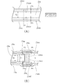
以上説明した手順で脱臭フィルタ23aと加熱部23fとを組み付けたときの、脱臭フィルタ23aと前面側放熱板23caおよび背面側放熱板23cbとの位置決めについて、図8を用いて説明する。ここで、図8(A)は図6における要部Mを真横から見た場合の概略図、図8(B)は図6における要部Nを真横から見た場合の概略図である。   Positioning of the deodorizing filter 23a, the front-side heat radiating plate 23ca, and the rear-side heat radiating plate 23cb when the deodorizing filter 23a and the heating unit 23f are assembled according to the procedure described above will be described with reference to FIG. Here, FIG. 8A is a schematic view when the main part M in FIG. 6 is viewed from the side, and FIG. 8B is a schematic view when the main part N in FIG. 6 is viewed from the side.

前述したように、背面側放熱板23cbの本体部23ccのフィルタ対向面23ccaと、第1接合面23cdおよび第2接合面23ceaとの間の高さ寸法Hは、脱臭フィルタ23aの第1歯車23acの厚さ寸法T1より大きい寸法とされている。また、図8(B)に示すように、外側ローラ23noを第3軸23qに嵌合させたときに、前面側ケース23eaの第2フランジ23uと上フランジ23ncとの間の寸法、および、背面側ケース23ebの第2フランジ23xと下フランジ23ndとの間の寸法は、それぞれP1とされている。さらには、外側ローラ23noの上フランジ23ncと下フランジ23ndとの間に脱臭フィルタ23aの第1歯車23acを装着したときに、第1歯車23acと上フランジ23ncおよび下フランジ23ndとの間の寸法は、それぞれP2(=(S−T1)/2)とされている。このとき、外側ローラ23noの前後方向の可動範囲は、前面側ケース23eaおよび背面側ケース23ebによって寸法P1で規制される。また、脱臭フィルタ23aの前後方向の可動範囲は、上フランジ23ncおよび下フランジ23ndによって寸法P2で規制される。
尚、図示は省略しているが、内側ローラ23niと前面側ケース23eaおよび背面側ケース23ebとの位置関係や、内側ローラ23niと脱臭フィルタ23aとの位置関係も、上述した外側ローラ23noと同じとされている。
As described above, the height dimension H between the filter facing surface 23cca of the main body portion 23cc of the back side heat radiating plate 23cb and the first joint surface 23cd and the second joint surface 23cea is determined by the first gear 23ac of the deodorizing filter 23a. The thickness is larger than T1. Further, as shown in FIG. 8B, when the outer roller 23no is fitted to the third shaft 23q, the dimension between the second flange 23u and the upper flange 23nc of the front case 23ea, and the rear surface The dimensions between the second flange 23x and the lower flange 23nd of the side case 23eb are P1 respectively. Further, when the first gear 23ac of the deodorizing filter 23a is mounted between the upper flange 23nc and the lower flange 23nd of the outer roller 23no, the dimension between the first gear 23ac and the upper flange 23nc and the lower flange 23nd is , P2 (= (S−T1) / 2). At this time, the movable range in the front-rear direction of the outer roller 23no is regulated by the dimension P1 by the front side case 23ea and the back side case 23eb. Further, the movable range in the front-rear direction of the deodorizing filter 23a is restricted by the dimension P2 by the upper flange 23nc and the lower flange 23nd.
Although not shown, the positional relationship between the inner roller 23ni and the front case 23ea and the rear case 23eb and the positional relationship between the inner roller 23ni and the deodorizing filter 23a are the same as those of the outer roller 23no described above. Has been.

一方、図8(A)に示すように、脱臭フィルタ23aのフィルタ本体表面と前面側放熱板23caのフィルタ対向面23caaとの間の寸法、および、脱臭フィルタ23aのフィルタ本体表面と背面側放熱板23cbの本体部23ccのフィルタ対向面23ccaとの間の寸法は、それぞれP3(=(H−T2)/2)とされている。ここで、図8(A)に示すように、寸法P1、P2、P3の関係が、P1+P2<P3、となるように、寸法S、厚さ寸法T1およびT2、高さ寸法H、および、前面側ケース23eaの第2フランジ23uと背面側ケース23ebの第2フランジ23xとの間隔寸法を定めれば、脱臭フィルタ23aが駆動部23hによって回転するときに、脱臭フィルタ23aが前面側放熱板23caと背面側放熱板23cbに接触することなく安定して回転させることができる。   On the other hand, as shown in FIG. 8 (A), the dimension between the filter main body surface of the deodorizing filter 23a and the filter facing surface 23caa of the front side heat radiating plate 23ca, and the filter main body surface and the rear side heat radiating plate of the deodorizing filter 23a. The dimension between the 23cb main body portion 23cc and the filter facing surface 23cca is P3 (= (H−T2) / 2), respectively. Here, as shown in FIG. 8 (A), the dimension S, the thickness dimensions T1 and T2, the height dimension H, and the front surface are set such that the relationship among the dimensions P1, P2, and P3 is P1 + P2 <P3. If the distance between the second flange 23u of the side case 23ea and the second flange 23x of the back side case 23eb is determined, when the deodorizing filter 23a is rotated by the drive unit 23h, the deodorizing filter 23a is separated from the front side heat sink 23ca. It can be rotated stably without coming into contact with the rear side heat sink 23cb.

尚、以上説明した本実施形態では、脱臭フィルタ23aと前面側放熱板23caとの間隔寸法と、脱臭フィルタ23aと背面側放熱板23cbとの間隔寸法とが同じ寸法P3とされているが、脱臭フィルタ23aと各放熱板との間隔寸法は異なる寸法であってもよい。   In the present embodiment described above, the distance between the deodorizing filter 23a and the front-side heat sink 23ca and the distance between the deodorizing filter 23a and the rear-side heat sink 23cb are the same dimension P3. The distance between the filter 23a and each heat sink may be different.

次に、図6を用いて、組み立てた加熱部23fおよび脱臭フィルタ23aを、保持部23gに装着する際に必要となる部材および装着方法について説明する。保持部23gは、合成樹脂材を使用して略四角形状に形成されており、中央部に脱臭フィルタ23aの形状に応じた開口部23gdが設けられ、また、開口部23gdの上方(保持部23gを通風路10に配置したときに上側となる箇所。以下、上方と記載)には、加熱部23fの形状に応じて凹形状とされた加熱部固定部23geが設けられている。2本の第1軸23gaは保持部23gの下方(保持部23gを通風路10に配置したときに下側となる箇所。以下、下方と記載)の両隅に配置されており、各々にローラ23mの孔23maが挿入されてローラ23mを回転自在に保持する。第2軸23gbは、加熱部固定部23geの左側(脱臭フィルタ23aを前面側から見た場合の左側)に配置されており、第2歯車23kが挿入されて第2歯車23kを回動自在に保持する。駆動部固定部23gcは、加熱部固定部23geの右側(脱臭フィルタ23aを前面側から見た場合の右側)に配置されており、駆動部23hを保持する。   Next, with reference to FIG. 6, a description will be given of members and mounting methods required when mounting the assembled heating unit 23f and deodorizing filter 23a on the holding unit 23g. The holding portion 23g is formed in a substantially square shape using a synthetic resin material, and an opening portion 23gd corresponding to the shape of the deodorizing filter 23a is provided in the central portion, and above the opening portion 23gd (the holding portion 23g). A heating portion fixing portion 23ge having a concave shape according to the shape of the heating portion 23f is provided at a location on the upper side when arranged in the ventilation path 10. Hereinafter, the upper portion is described. The two first shafts 23ga are arranged at both corners below the holding portion 23g (lower portions when the holding portion 23g is arranged in the air passage 10; hereinafter referred to as “lower”). A 23 m hole 23 ma is inserted to hold the roller 23 m rotatably. The second shaft 23gb is disposed on the left side (left side when the deodorizing filter 23a is viewed from the front side) of the heating unit fixing unit 23ge, and the second gear 23k is inserted to rotate the second gear 23k. Hold. The driving unit fixing unit 23gc is disposed on the right side of the heating unit fixing unit 23ge (the right side when the deodorizing filter 23a is viewed from the front side) and holds the driving unit 23h.

駆動部23hは、例えばステッピングモータであり、その出力軸に合成樹脂材で形成された駆動歯車23jが取り付けられる。駆動歯車23jは脱臭フィルタ23aの第1歯車23acと噛みあう歯車である。   The drive unit 23h is, for example, a stepping motor, and a drive gear 23j formed of a synthetic resin material is attached to the output shaft thereof. The drive gear 23j is a gear that meshes with the first gear 23ac of the deodorizing filter 23a.

第2歯車23kは、合成樹脂材で形成されており、駆動歯車23jと同様に脱臭フィルタ23aの第1歯車23acと噛みあう歯車である。回転検出部23rは、例えばフォトインタラプタ(対抗する発光部と受光部とを有し、発光部からの光を物体が遮るのを受光部で検出することによって、物体の有無や位置を判定するセンサ)であり、第2歯車23kの回転を検出することで、脱臭フィルタ23aが回転しているか否か検出するために設けられている。   The second gear 23k is formed of a synthetic resin material, and is a gear that meshes with the first gear 23ac of the deodorizing filter 23a, like the drive gear 23j. The rotation detection unit 23r is, for example, a photo interrupter (a sensor that has a light emitting unit and a light receiving unit that oppose each other, and detects the presence or position of an object by detecting that the object blocks light from the light emitting unit. ) And is provided to detect whether or not the deodorizing filter 23a is rotating by detecting the rotation of the second gear 23k.

4枚の押さえ部材23zは、合成樹脂材を使用して略五角形状の板材に形成され、保持部23gに嵌め込むことができる形状とされている。押さえ部材23zは、ローラ23mや駆動歯車23j、第2歯車23kを保持部23gに装着した後これらを押さえて保持部23gから外れないようにするものである。   The four pressing members 23z are formed in a substantially pentagonal plate material using a synthetic resin material, and have a shape that can be fitted into the holding portion 23g. The pressing member 23z is configured to prevent the roller 23m, the drive gear 23j, and the second gear 23k from being detached from the holding portion 23g after being mounted on the holding portion 23g.

2個のローラ23mは、合成樹脂材を用いて形成されており、筒部23mbと、上フランジ23mcと、下フランジ23mdとを有しており、筒部23mbには孔23maが設けられている。本実施形態においては、ローラ23mは図7で説明したローラ23nと同じ形状であり、上フランジ23mcと下フランジ23mdとの間の寸法も、ローラ23ンと同じ寸法Sとなっているため、ローラ23mの詳細な説明は省略する。   The two rollers 23m are formed using a synthetic resin material, and have a cylindrical portion 23mb, an upper flange 23mc, and a lower flange 23md, and the cylindrical portion 23mb is provided with a hole 23ma. . In this embodiment, the roller 23m has the same shape as the roller 23n described in FIG. 7, and the dimension between the upper flange 23mc and the lower flange 23md is the same dimension S as the roller 23n. Detailed description of 23m is omitted.

以上説明した部材を用いた、加熱部23fおよび脱臭フィルタ23aの保持部23gへの装着は次のように行われる。まず、保持部23gの2本の第1軸23gaの各々にローラ23mの孔23maを嵌合させて2個のローラ23mを保持部23gに装着する。次に、保持部23gの第2軸23gbに、回転検出部23r、第2歯車23kの順に装着する。次に、駆動部23hの出力軸に駆動歯車23jを装着し、保持部23gの駆動部固定部23gcに駆動部23hを固定する。   The mounting of the heating unit 23f and the deodorizing filter 23a to the holding unit 23g using the members described above is performed as follows. First, the hole 23ma of the roller 23m is fitted to each of the two first shafts 23ga of the holding portion 23g, and the two rollers 23m are attached to the holding portion 23g. Next, the rotation detecting unit 23r and the second gear 23k are mounted in this order on the second shaft 23gb of the holding unit 23g. Next, the drive gear 23j is attached to the output shaft of the drive unit 23h, and the drive unit 23h is fixed to the drive unit fixing unit 23gc of the holding unit 23g.

次に、加熱部23fおよび脱臭フィルタ23aを保持部23gに装着する。具体的には、加熱部23fを保持部23gの加熱部固定部23geに挿入して固定するとともに、2個のローラ23mの上フランジ23mcと下フランジ23mdとの間に第1歯車23acが嵌まるように、また、駆動歯車23jと第2歯車23kとが脱臭フィルタ23aの第1歯車23acに噛みあうように、脱臭フィルタ23aが装着される。これにより、駆動部23hにより駆動歯車23を回転させることによって、第2歯車23kと2個のローラ23mにガイドされた脱臭フィルタ23aが安定して回転する。   Next, the heating part 23f and the deodorizing filter 23a are attached to the holding part 23g. Specifically, the heating unit 23f is inserted and fixed to the heating unit fixing unit 23ge of the holding unit 23g, and the first gear 23ac is fitted between the upper flange 23mc and the lower flange 23md of the two rollers 23m. Similarly, the deodorizing filter 23a is mounted so that the drive gear 23j and the second gear 23k mesh with the first gear 23ac of the deodorizing filter 23a. Thereby, by rotating the drive gear 23 by the drive unit 23h, the deodorizing filter 23a guided by the second gear 23k and the two rollers 23m is stably rotated.

最後に、4枚の押さえ部材23zを、2個のローラ23mの上方や、駆動歯車23j、第2歯車23kの上方にそれぞれ嵌め込んで、脱臭ユニット23の組み立てが完了する。組み立てられた脱臭ユニット23は、前述したように仕切板16における集塵ユニット22の背面側に保持部23gが固定されることで、空気清浄機1の通風路10に配置される。   Finally, the four pressing members 23z are fitted above the two rollers 23m and above the drive gear 23j and the second gear 23k, respectively, and the assembly of the deodorizing unit 23 is completed. The assembled deodorizing unit 23 is arranged in the ventilation path 10 of the air purifier 1 by fixing the holding portion 23g to the back side of the dust collecting unit 22 in the partition plate 16 as described above.

脱臭ユニット23が通風路10に配置され、各空気吸込口から通風路10に流入した空気が脱臭フィルタ23aを通過するとき、保持部23gの中央部に設けられた脱臭フィルタ23aの形状に応じた開口部23gd以外の箇所に流れようとする空気は、保持部23gによって遮られて脱臭フィルタ23aの通風面(脱臭フィルタ23aの加熱部23fで覆われていない部分)に導かれる。また、図5および図6に示すように、脱臭フィルタ23aの中心孔23adも、前面側ケース23eaの前面側カバー部23sと背面側ケース23ebの背面側カバー部23vとで覆われるので、脱臭フィルタ23aの中心孔23adに流れる空気はその流れを遮られて脱臭フィルタ23aの通風面に導かれる。つまり、以上説明した構成の脱臭ユニット23では、通風路10に流入して脱臭ユニット23を通過する空気が効率よく脱臭フィルタ23aに導かれるので、より効果的に空気の脱臭が行える。   When the deodorizing unit 23 is arranged in the ventilation path 10 and the air flowing into the ventilation path 10 from each air suction port passes through the deodorization filter 23a, it corresponds to the shape of the deodorization filter 23a provided in the central part of the holding part 23g. Air that is about to flow to locations other than the opening 23gd is blocked by the holding portion 23g and guided to the ventilation surface of the deodorizing filter 23a (portion not covered by the heating portion 23f of the deodorizing filter 23a). Further, as shown in FIGS. 5 and 6, the center hole 23ad of the deodorizing filter 23a is also covered with the front side cover part 23s of the front side case 23ea and the rear side cover part 23v of the rear side case 23eb. The air flowing through the central hole 23ad of the 23a is blocked and guided to the ventilation surface of the deodorizing filter 23a. That is, in the deodorizing unit 23 having the above-described configuration, the air that flows into the ventilation path 10 and passes through the deodorizing unit 23 is efficiently guided to the deodorizing filter 23a, so that the air can be deodorized more effectively.

以上説明した構成を有する空気清浄機1において、使用者が操作部15を操作して空気清浄機1の運転を開始すると、送風機25が駆動するとともに、集塵ユニット22の第1電気集塵機22aおよび第2電気集塵機22bに通電が開始され、加湿ユニット24の加湿フィルタ24aが回転を開始する。送風機25が駆動すると、上面吸込口13a、右側面吸込口13b、および左側面吸込口13cから本体部11内部に空気が吸い込まれる。   In the air cleaner 1 having the above-described configuration, when the user operates the operation unit 15 to start the operation of the air cleaner 1, the blower 25 is driven, and the first electric dust collector 22a of the dust collection unit 22 and Energization of the second electric dust collector 22b is started, and the humidifying filter 24a of the humidifying unit 24 starts rotating. When the blower 25 is driven, air is sucked into the main body 11 from the upper surface suction port 13a, the right side suction port 13b, and the left side suction port 13c.

本体部11内部に吸い込まれた空気は、1)通風路10における脱臭ユニット23の下部と加湿ユニット24の上部とが前後方向に重なって配置される箇所では、プレフィルタ21→集塵ユニット22→脱臭ユニット23→加湿ユニット24の順に、2)通風路10における脱臭ユニット23の下部と加湿ユニット24の上部とが前後方向に重なって配置されていない箇所では、プレフィルタ21→集塵ユニット22→脱臭ユニット23の順に、または、プレフィルタ21→集塵ユニット22→加湿ユニット24の順に、それぞれ流れて、上面吹出口14a、右側面吹出口14b、および左側面吹出口14cから空気清浄機1が設置された室内に吹き出される。   The air sucked into the inside of the main body 11 is: 1) In a place where the lower part of the deodorizing unit 23 and the upper part of the humidifying unit 24 are arranged in the front-rear direction in the ventilation path 10, the prefilter 21 → the dust collecting unit 22 → In the order of deodorizing unit 23 → humidifying unit 24, 2) in the place where the lower part of deodorizing unit 23 and the upper part of humidifying unit 24 in ventilation path 10 are not overlapped in the front-rear direction, prefilter 21 → dust collecting unit 22 → The air purifier 1 flows in the order of the deodorizing unit 23 or in the order of the prefilter 21 → the dust collecting unit 22 → the humidifying unit 24, and the air cleaner 1 passes through the upper surface outlet 14a, the right side outlet 14b, and the left side outlet 14c. It is blown out into the installed room.

上記のように空気清浄機1内部の通風路10を空気が通過する際に、プレフィルタ21および通電されている集塵ユニット22で塵埃や花粉が除去される。そして、保持部23gの開口部23gdを介して脱臭フィルタ23aの通風面(脱臭ユニット23の加熱部23fから通風路10に露出した面)を空気が通過する際に、臭気成分が除去されるとともに、加湿ユニット24を空気が通過する際に加湿される。尚、上述したように、脱臭ユニット23より各空気吸込口側に集塵ユニット22が配置されているので、脱臭ユニット23に流入する空気は塵埃や花粉等が除去されており、塵埃や花粉等によって脱臭ユニット23の脱臭フィルタ23aが目詰まりすることがない。   As described above, when air passes through the ventilation path 10 inside the air purifier 1, dust and pollen are removed by the pre-filter 21 and the energized dust collection unit 22. And when air passes through the ventilation surface (surface exposed to the ventilation path 10 from the heating part 23f of the deodorizing unit 23) of the deodorizing filter 23a through the opening 23gd of the holding part 23g, the odor component is removed. When the air passes through the humidifying unit 24, it is humidified. As described above, since the dust collection unit 22 is disposed on the air inlet side of the deodorizing unit 23, the air flowing into the deodorizing unit 23 is free from dust, pollen, dust, pollen, etc. Therefore, the deodorizing filter 23a of the deodorizing unit 23 is not clogged.

また、空気清浄機1を運転しているときは、PTCヒータ23bへの通電を継続して行うとともに、駆動部23hを駆動して脱臭フィルタ23aを所定時間(脱臭フィルタ23aの脱臭能力の再生に必要な時間であり、例えば2時間)毎に所定角度(例えば、30度)回転させることで、脱臭フィルタ23aにおける加熱部23fで覆われる箇所の脱臭能力の再生を行っている。つまり、空気清浄機1の運転中は、脱臭フィルタ23aの加熱部23fで覆われる場所の脱臭能力の再生を行いつつ、これ以外の箇所で空気の脱臭を行っている。   When the air purifier 1 is in operation, the PTC heater 23b is continuously energized, and the drive unit 23h is driven to operate the deodorizing filter 23a for a predetermined time (to regenerate the deodorizing ability of the deodorizing filter 23a). The deodorizing ability of the portion covered with the heating unit 23f in the deodorizing filter 23a is regenerated by rotating it at a predetermined angle (for example, 30 degrees) every necessary time, for example, 2 hours. That is, during the operation of the air purifier 1, air is deodorized at other locations while regenerating the deodorizing ability of the place covered with the heating unit 23 f of the deodorizing filter 23 a.

前述したように、PTCヒータ23bは前面側放熱板23caに取り付けられているが、背面側放熱板23cbの第1接合部23cdの第1接合面23cdaと第2接合部23ceの第2接合面23ceaとが前面側放熱板23caのフィルタ対向面23caaに接しているので、PTCヒータ23bで発生した熱は、前面側放熱板23caの両端部から第1接合部23cdおよび第2接合部23ceを通して背面側放熱板23cbに効率よく伝導する。これにより、加熱部23fにおいて、発熱体としてのPTCヒータ23bで脱臭フィルタ23aの前面側と背面側の両面側を加熱して脱臭フィルタ23aの両面の脱臭能力の再生が行える。   As described above, the PTC heater 23b is attached to the front side heat radiating plate 23ca, but the first joint surface 23cda of the first joint portion 23cd of the rear side heat radiating plate 23cb and the second joint surface 23cea of the second joint portion 23ce. Is in contact with the filter-facing surface 23caa of the front side heat radiating plate 23ca, the heat generated by the PTC heater 23b is transmitted from both ends of the front side heat radiating plate 23ca to the back side through the first joint portion 23cd and the second joint portion 23ce. Conducts efficiently to the heat sink 23cb. Thereby, in the heating part 23f, both the front side and the back side of the deodorizing filter 23a can be heated by the PTC heater 23b as a heating element to regenerate the deodorizing ability of both sides of the deodorizing filter 23a.

尚、前面側放熱板23caと前面側ケース23eaの間と、背面側放熱板23cbと背面側ケース23ebの間には、各々断熱材23dが配置されているので、PTCヒータ23bによって加熱された前面側放熱板23caや背面側放熱板23cbから加熱部23fの外部に熱が逃げにくくなっており、PTCヒータ23bで発生した熱を効率よく脱臭フィルタ23aに加えることができる。   In addition, since the heat insulating material 23d is disposed between the front side heat radiating plate 23ca and the front side case 23ea, and between the rear side heat radiating plate 23cb and the back side case 23eb, the front surface heated by the PTC heater 23b. It is difficult for heat to escape from the side heat radiating plate 23ca and the back side heat radiating plate 23cb to the outside of the heating unit 23f, and heat generated by the PTC heater 23b can be efficiently added to the deodorizing filter 23a.

また、加熱部23fが脱臭フィルタ23aの一部のみ覆う構造となっているので、脱臭フィルタ23aの空気抵抗が小さい。また、前述したように集塵ユニット22も空気抵抗が小さい。これにより、シロッコファンと比べて静圧が低い、つまり、同じ空気抵抗がある場合においてシロッコファンより風量が小さいが、シロッコファンと比べて効率が高く騒音が小さいターボファン25aを送風機25に用いることができるので、必要な集塵能力や脱臭能力を確保しつつ騒音を抑制した空気清浄機1を実現できる。   Moreover, since the heating part 23f has a structure which covers only a part of the deodorizing filter 23a, the air resistance of the deodorizing filter 23a is small. Further, as described above, the dust collection unit 22 also has a low air resistance. As a result, when the static pressure is lower than that of the sirocco fan, that is, when the air resistance is the same, the air volume is smaller than that of the sirocco fan, but the turbo fan 25a is more efficient and lower in noise than the sirocco fan. Therefore, it is possible to realize the air cleaner 1 that suppresses noise while ensuring the necessary dust collection ability and deodorizing ability.

また、集塵ユニット22や脱臭ユニット23の空気抵抗が小さいので、図3および図4に示したように、上面吸込口13a、右側面吸込口13b、および左側面吸込口13cから上面吹出口14a、右側面吹出口14b、および左側面吹出口14cに向かって、集塵ユニット22、脱臭ユニット23、加湿ユニット24、送風機25の順に並べて配置しても空気抵抗がさほど大きくならないので、送風機25の駆動によって本体部11内部の通風路10を流れる空気量が低下しない。そして、上記のように各構成を並べて配置することによって、本体部11が前後(奥行き)方向の寸法が長くなり、かつ、本体部11の前面側に各空気吸込口を配置し本体部11の背面側に各空気吹出口を配置しているので、図4に示す各空気吸込口と各空気吹出口との距離Lを大きくすることができる。これにより、各空気吹出口から室内に吹き出された空気がすぐに各空気吸込口から空気清浄機1内部に吸い込まれる、所謂空気吸込口と空気吹出口との間のショートサーキットの発生が抑制される。   Further, since the air resistance of the dust collection unit 22 and the deodorizing unit 23 is small, as shown in FIGS. 3 and 4, the upper surface outlet 14a is connected to the upper surface inlet 13a, the right side inlet 13b, and the left side inlet 13c. The air resistance does not increase so much even if the dust collecting unit 22, the deodorizing unit 23, the humidifying unit 24, and the blower 25 are arranged in this order toward the right side blower outlet 14b and the left side blower outlet 14c. The amount of air flowing through the ventilation path 10 inside the main body 11 is not reduced by driving. Then, by arranging the components side by side as described above, the main body portion 11 has a longer dimension in the front-rear (depth) direction, and each air suction port is disposed on the front side of the main body portion 11 to Since the air outlets are arranged on the back side, the distance L between each air inlet and each air outlet shown in FIG. 4 can be increased. As a result, the occurrence of a short circuit between the air inlet and the air outlet, in which the air blown into the room from each air outlet is immediately sucked into the air cleaner 1 from each air inlet, is suppressed. The

上述したショートサーキットが発生しづらい距離Lを実現できるので、本体部11前方の上端部、右側端部、左側端部の3方向から空気清浄機1内部に空気を吸込むための上面吸込口13a、右側面吸込口13b、および左側面吸込口13cを備えることができ、また、本体部11後方の上端部、右側端部、左側端部から3方向へ空気を吹き出すための上面吹出口14a、右側面吹出口14b、および左側面吹出口14cを備えることができる。従って、空気吸込口および空気吹出口の面積を大きくでき、空気の吸い込み量や吹き出し量を十分に確保できるとともに、3方向からの空気の吸い込みおよび吹き出しを行うことで、空気清浄機1が設置された室内の空気をまんべんなく吸い込んで集塵・加湿および脱臭し、浄化した空気を吹き出して室内に行き渡らせることができる。   Since the distance L in which the short circuit described above is difficult to occur can be realized, the upper surface suction port 13a for sucking air into the air cleaner 1 from the three directions of the upper end, the right end, and the left end in front of the main body 11, A right side suction port 13b and a left side suction port 13c can be provided, and an upper surface outlet 14a for blowing air in three directions from the upper end, the right end, and the left end behind the main body 11, and the right side A surface outlet 14b and a left side outlet 14c can be provided. Accordingly, the area of the air inlet and the air outlet can be increased, the air intake amount and the air discharge amount can be sufficiently secured, and the air cleaner 1 is installed by performing air intake and air discharge from three directions. The air can be sucked evenly to collect, humidify, and deodorize the air, and the purified air can be blown out and distributed throughout the room.

尚、図3の線分Pに示すように、ファンモータ25bの中心の高さを、集塵ユニット22の第1電気集塵機22aと第2電気集塵機22bとの間の空間の高さに合せるように、集塵ユニット22および送風機25を配置することが望ましい。ファンモータ25bの中心付近には、ターボファン25aの回転による空気の流れが少ないため、本体部11内部におけるファンモータ25bの中心付近の空間での空気の流れは少ない。そこで、集塵ユニット22のうち空気が通過しても集塵能力のない第1電気集塵機22aと第2電気集塵機22bとの間の空間の高さを、ファンモータ25bの中心の高さに合わせることによって、空気の流れが多いターボファン25aの羽根が存在する空間に第1電気集塵機22aと第2電気集塵機22bとを配置することとなるので、効率的に集塵ユニット22での除塵が行える。   3, the center height of the fan motor 25b is adjusted to the height of the space between the first electric dust collector 22a and the second electric dust collector 22b of the dust collection unit 22. In addition, it is desirable to arrange the dust collection unit 22 and the blower 25. In the vicinity of the center of the fan motor 25b, there is little air flow due to the rotation of the turbo fan 25a, so there is little air flow in the space near the center of the fan motor 25b inside the main body 11. Therefore, the height of the space between the first electric dust collector 22a and the second electric dust collector 22b, which has no dust collecting ability even when air passes, is adjusted to the height of the center of the fan motor 25b. As a result, the first electric dust collector 22a and the second electric dust collector 22b are arranged in a space where the blades of the turbo fan 25a where there is a large amount of air flow exist, so that the dust collection unit 22 can perform dust removal efficiently. .

以上説明した通り、本発明の空気清浄機は、脱臭フィルタの中心部に貫通孔を設け、この貫通孔と脱臭フィルタの外周部とで脱臭フィルタを支持することで、加熱部と脱臭フィルタとの距離を一定に保つ。従って、脱臭フィルタあるいは加熱部を回転させるときに、脱臭フィルタと加熱部とが接触して回転しないといった問題や、脱臭フィルタが加熱部に接触して損傷するといった問題が発生しない。   As described above, the air cleaner of the present invention has a through-hole at the center of the deodorizing filter, and the deodorizing filter is supported by the through-hole and the outer peripheral portion of the deodorizing filter. Keep the distance constant. Therefore, when rotating a deodorizing filter or a heating part, the problem that a deodorizing filter and a heating part contact and do not rotate, and the problem that a deodorizing filter contacts a heating part do not generate | occur | produce.

尚、以上説明した実施形態では、第1位置決め部材である3個のローラ23mが前面側ケース23eaに装着され、2個のローラ23mで脱臭フィルタ23aの外周部を支持し、残り1個のローラ23mで脱臭フィルタ23aの貫通孔23adを支持する場合について説明したが、脱臭フィルタ23aの外周部を支持するローラ23mが1個または3個以上であってもよく、また、脱臭フィルタ23aの貫通孔23adを支持するローラ23mが2個以上であってもよい。さらには、脱臭フィルタ23aが回転するときに前面側放熱板23caや背面側放熱板23cbに接触しないように脱臭フィルタ23aを支持できるのであれば、複数のローラ23mが前面側ケース23ea以外の箇所、例えば前面側放熱板23caに装着されていてもよい。   In the embodiment described above, the three rollers 23m serving as the first positioning member are mounted on the front case 23ea, the two rollers 23m support the outer peripheral portion of the deodorizing filter 23a, and the remaining one roller. Although the case where the through hole 23ad of the deodorizing filter 23a is supported by 23m has been described, the number of rollers 23m that support the outer peripheral portion of the deodorizing filter 23a may be one or three or more, and the through hole of the deodorizing filter 23a There may be two or more rollers 23m that support 23ad. Furthermore, if the deodorizing filter 23a can be supported so that it does not come into contact with the front side heat radiating plate 23ca and the rear side heat radiating plate 23cb when the deodorizing filter 23a rotates, a plurality of rollers 23m are provided at locations other than the front side case 23ea, For example, you may mount | wear with the front side heat sink 23ca.

また、以上説明した実施形態では、加熱部23fが保持部23gに固定され、脱臭フィルタ23aが駆動部23hによって回転する場合について説明したが、脱臭フィルタ23aが保持部23g等に固定されて、加熱部23fが脱臭フィルタ23aの円周に沿って回転してもよい。   In the embodiment described above, the heating unit 23f is fixed to the holding unit 23g and the deodorizing filter 23a is rotated by the driving unit 23h. However, the deodorizing filter 23a is fixed to the holding unit 23g and the like, The part 23f may rotate along the circumference of the deodorizing filter 23a.

1 空気清浄機
10 通風路
11 本体部
23 脱臭ユニット
23a 脱臭フィルタ
23aa 基材
23ab 触媒層
23ac 第1歯車
23ad 中心孔
23ae 覆い部
23b PTCヒータ
23c 放熱板
23ca 前面側放熱板
23caa フィルタ対向面
23cab ヒータ配置面
23cb 背面側放熱板
23cc 本体部
23cca フィルタ対向面
23ccb 断熱材配置面
23cd 第1接合部
23cda 第2接合面
23ce 第2接合部
23cea 第2接合面
23e ケース
23ea 前面側ケース
23eb 背面側ケース
23ec 放熱板収納部
23eca 底面
23ecb第1側面
23ecc 第2側面
23ecd 第3側面
23ece 第4側面
23ed 放熱板収納部
23eda 底面
23edb第1側面
23edc 第2側面
23edd 第3側面
23ede 第4側面
23f 加熱部
23g 保持部
23ga 第1軸
23gb 第2軸
23gc 駆動部固定部
23gd 開口部
23ge 加熱部固定部
23h 駆動部
23j 駆動歯車
23k 第2歯車
23m ローラ
23ma 孔
23mb 筒部
23mc 上フランジ
23md 下フランジ
23n ローラ
23na 孔
23nb 筒部
23nc 上フランジ
23nd 下フランジ
23ni 内側ローラ
23no 外側ローラ
23p ヒータケース
23q 第3軸
23r 回転検出部
23s 前面側カバー部
23t 前面側第1フランジ
23u 前面側第2フランジ
23v 背面側カバー部
DESCRIPTION OF SYMBOLS 1 Air cleaner 10 Ventilation path 11 Main-body part 23 Deodorizing unit 23a Deodorizing filter 23aa Base material 23ab Catalyst layer 23ac 1st gearwheel 23ad Center hole 23ae Cover part 23b PTC heater 23c Heat sink 23ca Front side heat sink 23caa Filter arrangement | positioning surface 23cab Surface 23cb Rear side heat sink 23cc Main body part 23cca Filter facing surface 23ccb Heat insulation material arrangement surface 23cd First joint part 23cda Second joint surface 23ce Second joint part 23cea Second joint surface 23e Case 23ea Front side case 23eb Back side case 23ec Plate storage portion 23eca Bottom surface 23ecb first side surface 23ecc Second side surface 23ecd Third side surface 23ece Fourth side surface 23ed Heat sink storage portion 23eda bottom surface 23edb first side surface 23edc second side surface 23 edd 3rd side surface 23ed 4th side surface 23f Heating part 23g Holding part 23ga 1st axis | shaft 23gb 2nd axis | shaft 23gc Drive part fixing | fixed part 23gd Opening part 23ge Heating part fixing | fixed part 23h Drive part 23j Drive gear 23k 2nd gear 23m Roller 23ma Hole 23mb Tube portion 23mc Upper flange 23md Lower flange 23n Roller 23na hole 23nb Tube portion 23nc Upper flange 23nd Lower flange 23ni Inner roller 23no Outer roller 23p Heater case 23q Third shaft 23r Rotation detection portion 23s Front side cover portion 23t Front side first flange 23u Front side second flange 23v Rear side cover

Claims (3)

筐体内に空気を取り込む空気吸込口と、筐体内から外部へ空気を放出する空気吹出口と、前記空気吸込口と前記空気吹出口とを連通させる通風路とを有し、
前記通風路内に、送風機と、同送風機の駆動により前記通風路内に取り込まれた空気を脱臭する脱臭ユニットとが配置された空気清浄機であって、
前記脱臭ユニットは、円板形状に形成されて中心部に貫通孔を設けた脱臭フィルタと、同脱臭フィルタの一部を覆うように配置されて同脱臭フィルタの一部を加熱する加熱部と、前記脱臭フィルタ及び前記加熱部を保持する保持部とを有し、
前記脱臭フィルタ全体を前記加熱部で加熱するために、同加熱部を固定するとともに前記脱臭フィルタを回転させる、あるいは、前記脱臭フィルタを固定するとともに前記加熱部を前記脱臭フィルタの外周部に沿って回転させる駆動部を有し、
前記駆動部によって前記脱臭フィルタあるいは前記加熱部が回転するとき、前記脱臭フィルタと前記加熱部とが接触しないように前記脱臭フィルタを支える複数の支持部材を有し、
前記支持部材は、筒部と、同筒部の両端に設けられた上フランジと下フランジとを備えるとともに、前記脱臭フィルタの厚み方向への可動範囲を前記上フランジと前記下フランジにより規制することで前記脱臭フィルタを支持し、
複数の前記支持部材は、少なくとも前記脱臭フィルタの内周部を支える第1支持部材と、前記脱臭フィルタの外周部を支える第2支持部材とを有する、
ことを特徴とする空気清浄機。
An air suction port that takes air into the housing, an air outlet that discharges air from inside the housing to the outside, and a ventilation path that communicates the air suction port and the air outlet,
An air cleaner in which a blower and a deodorizing unit for deodorizing air taken into the ventilation passage by driving the blower are disposed in the ventilation passage,
The deodorizing unit includes a deodorizing filter formed in a disc shape and provided with a through hole in the center, a heating unit arranged to cover a part of the deodorizing filter and heating a part of the deodorizing filter , A holding unit for holding the deodorizing filter and the heating unit;
In order to heat the entire deodorizing filter with the heating unit, the heating unit is fixed and the deodorizing filter is rotated, or the deodorizing filter is fixed and the heating unit is moved along the outer periphery of the deodorizing filter. Having a drive to rotate,
When the deodorizing filter or the heating unit is rotated by the drive unit, the deodorizing filter and the heating unit have a plurality of support members that support the deodorizing filter so that the heating unit does not come into contact with the driving unit.
The support member includes a cylindrical portion, and an upper flange and a lower flange provided at both ends of the cylindrical portion, and restricts a movable range in the thickness direction of the deodorizing filter by the upper flange and the lower flange. In supporting the deodorizing filter,
The plurality of support members include at least a first support member that supports an inner peripheral portion of the deodorizing filter and a second support member that supports an outer peripheral portion of the deodorizing filter.
An air purifier characterized by that.
前記支持部材は、前記筒部に設けられた孔に軸が挿入されることで回転自在な状態で保持されている、
ことを特徴とする請求項1に記載の空気清浄機。
The support member is held in a rotatable state by inserting a shaft into a hole provided in the cylindrical portion.
Air purifier according to claim 1, characterized in that.
前記加熱部は、ヒータと、同ヒータを収納するケースとを有し、
前記ケースに前記第1支持部材または前記第2支持部材の少なくとも一方の支持部材が配置される、
ことを特徴とする請求項1または請求項2のいずれか1項に記載の空気清浄機。
The heating unit includes a heater and a case that houses the heater,
At least one support member of the first support member or the second support member is disposed in the case.
The air cleaner according to any one of claims 1 and 2 .
JP2014178066A 2014-09-02 2014-09-02 Air cleaner Active JP6405802B2 (en)

Priority Applications (1)

Application Number Priority Date Filing Date Title
JP2014178066A JP6405802B2 (en) 2014-09-02 2014-09-02 Air cleaner

Applications Claiming Priority (1)

Application Number Priority Date Filing Date Title
JP2014178066A JP6405802B2 (en) 2014-09-02 2014-09-02 Air cleaner

Publications (2)

Publication Number Publication Date
JP2016049402A JP2016049402A (en) 2016-04-11
JP6405802B2 true JP6405802B2 (en) 2018-10-17

Family

ID=55657374

Family Applications (1)

Application Number Title Priority Date Filing Date
JP2014178066A Active JP6405802B2 (en) 2014-09-02 2014-09-02 Air cleaner

Country Status (1)

Country Link
JP (1) JP6405802B2 (en)

Families Citing this family (2)

* Cited by examiner, † Cited by third party
Publication number Priority date Publication date Assignee Title
JP6888353B2 (en) * 2017-03-17 2021-06-16 株式会社富士通ゼネラル Suction unit and air purifier
JP6972740B2 (en) * 2017-07-31 2021-11-24 株式会社富士通ゼネラル Filter drive unit, suction unit and air purifier

Family Cites Families (3)

* Cited by examiner, † Cited by third party
Publication number Priority date Publication date Assignee Title
JP2011036782A (en) * 2009-08-10 2011-02-24 Zojirushi Corp Dehumidifier and method of controlling operation of the same
CN103476437B (en) * 2011-04-21 2017-04-26 三菱电机株式会社 Air purifier
JP5201275B1 (en) * 2012-01-20 2013-06-05 三菱電機株式会社 Air cleaner

Also Published As

Publication number Publication date
JP2016049402A (en) 2016-04-11

Similar Documents

Publication Publication Date Title
JP5999149B2 (en) Air cleaner
JP5900562B1 (en) Air cleaner
WO2016031782A1 (en) Air purifier
JP6405802B2 (en) Air cleaner
JP5900678B1 (en) Air cleaner
JP6405803B2 (en) Air cleaner
JP5958507B2 (en) Air cleaner
JP6405798B2 (en) Air cleaner
JP6897158B2 (en) Suction unit and air purifier
JP2018167147A (en) Absorption unit and air cleaner
JP6848347B2 (en) Suction unit and air purifier
JP6897156B2 (en) Suction unit and air purifier
JP6229772B1 (en) Adsorption unit and air purifier
JP6281593B2 (en) Air cleaner
JP6897157B2 (en) Suction unit and air purifier
JP6930156B2 (en) Suction unit and air purifier
JP6729531B2 (en) Adsorption unit and air purifier
WO2015186804A1 (en) Air cleaner
JP6888353B2 (en) Suction unit and air purifier
JP6972740B2 (en) Filter drive unit, suction unit and air purifier
JP6020843B2 (en) Air cleaner
JP2018164592A (en) Filter unit and air cleaner
JP2018000510A (en) Adsorption unit and air cleaner
JP2015230145A (en) Air cleaner
JP2016056985A (en) Air conditioner

Legal Events

Date Code Title Description
A621 Written request for application examination

Free format text: JAPANESE INTERMEDIATE CODE: A621

Effective date: 20170824

A977 Report on retrieval

Free format text: JAPANESE INTERMEDIATE CODE: A971007

Effective date: 20180523

A131 Notification of reasons for refusal

Free format text: JAPANESE INTERMEDIATE CODE: A131

Effective date: 20180529

A521 Written amendment

Free format text: JAPANESE INTERMEDIATE CODE: A523

Effective date: 20180726

TRDD Decision of grant or rejection written
A01 Written decision to grant a patent or to grant a registration (utility model)

Free format text: JAPANESE INTERMEDIATE CODE: A01

Effective date: 20180821

A61 First payment of annual fees (during grant procedure)

Free format text: JAPANESE INTERMEDIATE CODE: A61

Effective date: 20180903

R151 Written notification of patent or utility model registration

Ref document number: 6405802

Country of ref document: JP

Free format text: JAPANESE INTERMEDIATE CODE: R151