JP6401302B2 - Radiotherapy device and quality control method of radiotherapy device - Google Patents
Radiotherapy device and quality control method of radiotherapy device Download PDFInfo
- Publication number
- JP6401302B2 JP6401302B2 JP2016570337A JP2016570337A JP6401302B2 JP 6401302 B2 JP6401302 B2 JP 6401302B2 JP 2016570337 A JP2016570337 A JP 2016570337A JP 2016570337 A JP2016570337 A JP 2016570337A JP 6401302 B2 JP6401302 B2 JP 6401302B2
- Authority
- JP
- Japan
- Prior art keywords
- radiation
- reference image
- irradiation head
- center point
- acquisition unit
- Prior art date
- Legal status (The legal status is an assumption and is not a legal conclusion. Google has not performed a legal analysis and makes no representation as to the accuracy of the status listed.)
- Active
Links
- 238000001959 radiotherapy Methods 0.000 title claims description 61
- 238000003908 quality control method Methods 0.000 title claims description 48
- 230000005855 radiation Effects 0.000 claims description 111
- 238000000034 method Methods 0.000 claims description 21
- 238000012937 correction Methods 0.000 claims description 7
- 230000001678 irradiating effect Effects 0.000 claims description 6
- 239000003550 marker Substances 0.000 claims description 2
- 239000012491 analyte Substances 0.000 claims 1
- 230000000694 effects Effects 0.000 description 13
- 206010028980 Neoplasm Diseases 0.000 description 11
- 238000010586 diagram Methods 0.000 description 7
- 230000008859 change Effects 0.000 description 6
- 239000002245 particle Substances 0.000 description 6
- 230000008569 process Effects 0.000 description 6
- 210000001519 tissue Anatomy 0.000 description 6
- 238000003384 imaging method Methods 0.000 description 4
- 201000011510 cancer Diseases 0.000 description 3
- 238000005516 engineering process Methods 0.000 description 3
- 238000005259 measurement Methods 0.000 description 3
- 238000002560 therapeutic procedure Methods 0.000 description 3
- 230000008901 benefit Effects 0.000 description 2
- 239000012141 concentrate Substances 0.000 description 2
- 238000012790 confirmation Methods 0.000 description 2
- 238000001514 detection method Methods 0.000 description 2
- 238000010894 electron beam technology Methods 0.000 description 2
- 239000010419 fine particle Substances 0.000 description 2
- 230000014509 gene expression Effects 0.000 description 2
- 230000003211 malignant effect Effects 0.000 description 2
- 238000012986 modification Methods 0.000 description 2
- 230000004048 modification Effects 0.000 description 2
- 230000009467 reduction Effects 0.000 description 2
- 208000017520 skin disease Diseases 0.000 description 2
- 238000001356 surgical procedure Methods 0.000 description 2
- GUTLYIVDDKVIGB-OUBTZVSYSA-N Cobalt-60 Chemical compound [60Co] GUTLYIVDDKVIGB-OUBTZVSYSA-N 0.000 description 1
- 230000003247 decreasing effect Effects 0.000 description 1
- 238000009795 derivation Methods 0.000 description 1
- 201000010099 disease Diseases 0.000 description 1
- 208000037265 diseases, disorders, signs and symptoms Diseases 0.000 description 1
- 238000011347 external beam therapy Methods 0.000 description 1
- 230000005484 gravity Effects 0.000 description 1
- 230000003902 lesion Effects 0.000 description 1
- 210000000056 organ Anatomy 0.000 description 1
- 230000002265 prevention Effects 0.000 description 1
- 238000000275 quality assurance Methods 0.000 description 1
- 238000002673 radiosurgery Methods 0.000 description 1
- 210000003625 skull Anatomy 0.000 description 1
- 238000012360 testing method Methods 0.000 description 1
Images

Classifications
-
- A—HUMAN NECESSITIES
- A61—MEDICAL OR VETERINARY SCIENCE; HYGIENE
- A61N—ELECTROTHERAPY; MAGNETOTHERAPY; RADIATION THERAPY; ULTRASOUND THERAPY
- A61N5/00—Radiation therapy
- A61N5/10—X-ray therapy; Gamma-ray therapy; Particle-irradiation therapy
- A61N5/1048—Monitoring, verifying, controlling systems and methods
-
- A—HUMAN NECESSITIES
- A61—MEDICAL OR VETERINARY SCIENCE; HYGIENE
- A61N—ELECTROTHERAPY; MAGNETOTHERAPY; RADIATION THERAPY; ULTRASOUND THERAPY
- A61N5/00—Radiation therapy
- A61N5/10—X-ray therapy; Gamma-ray therapy; Particle-irradiation therapy
-
- A—HUMAN NECESSITIES
- A61—MEDICAL OR VETERINARY SCIENCE; HYGIENE
- A61N—ELECTROTHERAPY; MAGNETOTHERAPY; RADIATION THERAPY; ULTRASOUND THERAPY
- A61N5/00—Radiation therapy
- A61N5/10—X-ray therapy; Gamma-ray therapy; Particle-irradiation therapy
- A61N5/1048—Monitoring, verifying, controlling systems and methods
- A61N5/1049—Monitoring, verifying, controlling systems and methods for verifying the position of the patient with respect to the radiation beam
-
- A—HUMAN NECESSITIES
- A61—MEDICAL OR VETERINARY SCIENCE; HYGIENE
- A61N—ELECTROTHERAPY; MAGNETOTHERAPY; RADIATION THERAPY; ULTRASOUND THERAPY
- A61N5/00—Radiation therapy
- A61N5/10—X-ray therapy; Gamma-ray therapy; Particle-irradiation therapy
- A61N5/1048—Monitoring, verifying, controlling systems and methods
- A61N5/1064—Monitoring, verifying, controlling systems and methods for adjusting radiation treatment in response to monitoring
-
- A—HUMAN NECESSITIES
- A61—MEDICAL OR VETERINARY SCIENCE; HYGIENE
- A61N—ELECTROTHERAPY; MAGNETOTHERAPY; RADIATION THERAPY; ULTRASOUND THERAPY
- A61N5/00—Radiation therapy
- A61N5/10—X-ray therapy; Gamma-ray therapy; Particle-irradiation therapy
- A61N5/1048—Monitoring, verifying, controlling systems and methods
- A61N5/1075—Monitoring, verifying, controlling systems and methods for testing, calibrating, or quality assurance of the radiation treatment apparatus
-
- A—HUMAN NECESSITIES
- A61—MEDICAL OR VETERINARY SCIENCE; HYGIENE
- A61N—ELECTROTHERAPY; MAGNETOTHERAPY; RADIATION THERAPY; ULTRASOUND THERAPY
- A61N5/00—Radiation therapy
- A61N5/10—X-ray therapy; Gamma-ray therapy; Particle-irradiation therapy
- A61N5/1048—Monitoring, verifying, controlling systems and methods
- A61N5/1049—Monitoring, verifying, controlling systems and methods for verifying the position of the patient with respect to the radiation beam
- A61N2005/1054—Monitoring, verifying, controlling systems and methods for verifying the position of the patient with respect to the radiation beam using a portal imaging system
-
- A—HUMAN NECESSITIES
- A61—MEDICAL OR VETERINARY SCIENCE; HYGIENE
- A61N—ELECTROTHERAPY; MAGNETOTHERAPY; RADIATION THERAPY; ULTRASOUND THERAPY
- A61N5/00—Radiation therapy
- A61N5/10—X-ray therapy; Gamma-ray therapy; Particle-irradiation therapy
- A61N5/1048—Monitoring, verifying, controlling systems and methods
- A61N5/1075—Monitoring, verifying, controlling systems and methods for testing, calibrating, or quality assurance of the radiation treatment apparatus
- A61N2005/1076—Monitoring, verifying, controlling systems and methods for testing, calibrating, or quality assurance of the radiation treatment apparatus using a dummy object placed in the radiation field, e.g. phantom
Landscapes
- Health & Medical Sciences (AREA)
- Engineering & Computer Science (AREA)
- Biomedical Technology (AREA)
- Pathology (AREA)
- Nuclear Medicine, Radiotherapy & Molecular Imaging (AREA)
- Radiology & Medical Imaging (AREA)
- Life Sciences & Earth Sciences (AREA)
- Animal Behavior & Ethology (AREA)
- General Health & Medical Sciences (AREA)
- Public Health (AREA)
- Veterinary Medicine (AREA)
- Radiation-Therapy Devices (AREA)
Description
本発明は、放射線治療機器、及び放射線治療機器の品質管理方法に係り、さらに詳細には、EPID(electronic portal imaging device)のような映像獲得部を利用した放射線治療機器の品質管理方法において、EPIDの位置変化によって発生する誤差を算出し、それを補正する放射線治療機器、及び放射線治療機器の品質管理方法に関する。 The present invention relates to a radiotherapy device and a quality control method for the radiotherapy device, and more particularly, in a radiotherapy device quality control method using an image acquisition unit such as an electronic portal imaging device (EPID). The present invention relates to a radiotherapy device that calculates and corrects an error caused by a change in the position of the radiotherapy device, and a quality control method for the radiotherapy device.
放射線治療は、エックス線、ガンマ線のような高エネルギー波動、または電子線、陽性子線のような高エネルギー粒子を利用して、ターゲット組織に損傷を加えたり破壊したりすることにより、悪性組織の成長を遅延させたり阻止したりし、さらには消滅させる方法である。放射線治療は、癌だけではなく、良性腫瘍、内科的疾病、一部皮膚疾患の治療に利用されたりする。最近では、頭蓋骨を切開する神経外科的手術方式を代替し、切開手術なしに、一回で多量の放射線を照射して治療する放射線手術方法も開発されている。 Radiation therapy uses high-energy waves such as X-rays and gamma rays, or high-energy particles such as electron beams and positive beam, to grow or malignant tissue by damaging or destroying target tissues. Is a method of delaying, preventing, and even annihilating. Radiation therapy is used not only for cancer but also for the treatment of benign tumors, medical diseases, and some skin diseases. Recently, a radiosurgery method has been developed that replaces the neurosurgical method of incising the skull, and irradiates a large amount of radiation at one time without performing the incision operation.
最近では、癌患者の約60%以上が放射線治療を受けるほど一般化されている。放射線治療は、それ自体で腫瘍治療に利用されるだけではなく、腫瘍が大きく、浸襲されて手術が困難であるか、あるいは手術で除去することができない局所を治療する他の外科的手術と共に使用され、腫瘍の大きさを小さくし、外科的手術を容易にしたり、手術後に残った悪性細胞を破壊したりする用途に利用される。 Recently, more than about 60% of cancer patients have become so common that they receive radiation therapy. Radiation therapy is not only used for tumor treatment by itself, but along with other surgical procedures that treat areas where the tumor is large and invaded and difficult to operate or cannot be removed by surgery It is used for the purpose of reducing the size of a tumor, facilitating a surgical operation, or destroying malignant cells remaining after the operation.
外部から放射線を照射する体外放射線治療機器は、高エネルギー粒子や放射線を生成する方式により、低エネルギーエックス線治療機器、放射性同位元素治療装置、線形アクセレータ、粒子アクセレータなどに分類される。 External radiation therapy devices that emit radiation from the outside are classified into low energy X-ray therapy devices, radioisotope therapy devices, linear accelerators, particle accelerators, and the like according to the method of generating high energy particles and radiation.
低エネルギーエックス線治療機器は、エックス線発生装置を利用して、皮膚疾患や深部治療に利用されたが、現在ではほとんど使用されていない。 Low-energy X-ray treatment equipment has been used for skin diseases and deep treatment using an X-ray generator, but is rarely used at present.
放射性同位元素治療装置は、コバルト60(Co−60)のような放射性同位元素から発生するガンマ線を利用する。低エネルギーエックス線治療機器より若干強いエネルギーのガンマ線を利用するが、だんだんと使用が減っている。 The radioisotope treatment apparatus uses gamma rays generated from a radioisotope such as cobalt 60 (Co-60). It uses gamma rays with slightly stronger energy than low-energy X-ray therapy equipment, but the use is gradually decreasing.
線形加速器は、放射線治療の標準のように利用される装備であり、エックス線及び電子線の出力が可能であり、多様なエネルギーを伝達することができ、高い線量率、ビーム形状の調節(beam-forming)が可能である。 The linear accelerator is a device used like the standard of radiation therapy, and can output X-rays and electron beams, can transmit various energy, has high dose rate, and beam shape adjustment (beam- forming) is possible.
粒子加速器は、サイクロトロン加速器で加速した中性子や陽性子の粒子をビーム管を介して移送し、ノズルから所望する部位に放出する構造を有するが、線形加速器より深いブラッグピーク(Bragg’s peak)を有することができ、正常組織には線量を最小化し、深部の腫瘍にのみエネルギーを集中させることができる。 The particle accelerator has a structure in which neutrons and positron particles accelerated by a cyclotron accelerator are transported through a beam tube and emitted from a nozzle to a desired site, but has a Bragg's peak deeper than that of a linear accelerator. Can minimize the dose to normal tissues and concentrate energy only in deep tumors.
一般的に、かような医療用放射線装置は、意図的に患者の位置を変えるほど、または患者が無意識的に身を動かすほど診断の正確度や治療効果が落ち、病変周辺の正常組織に吸収される放射線線量が高くなり、時間及びコストが増大する。それにより、医療用放射線装置は、放射線放出ヘッドと検出部とが単に固定された位置で対向する方式で開発されていて、放射線放出ヘッドと検出部とがだんだんと患者の周囲を動くことができる形態に発展した。 In general, such medical radiological devices are absorbed into normal tissue around the lesion as the patient's position is intentionally changed or the patient moves unconsciously. The radiation doses that are made are higher, which increases time and cost. As a result, the medical radiation apparatus has been developed in such a manner that the radiation emission head and the detection unit face each other at a fixed position, and the radiation emission head and the detection unit can gradually move around the patient. It evolved into a form.
最近の医療用放射線装置は、アームを有したガントリに放射線放出ヘッドを装着する形態、またはリング状のガントリを有する方式にそれぞれ発展しており、放射線放出ヘッドと放射線検出器とが生体組織を挟んで対向し、放射線ソースと放射線検出器とが生体組織を中心に回転しなければならないので、リングガントリ(ring gantry)構造またはC−アームガントリ(C−arm gantry)構造が主に使用される。 Recent medical radiation devices have been developed into a configuration in which a radiation emitting head is attached to a gantry having an arm or a system having a ring-shaped gantry, and the radiation emitting head and the radiation detector sandwich biological tissue. Since the radiation source and the radiation detector must rotate about the living tissue, a ring gantry structure or a C-arm gantry structure is mainly used.
前述の背景技術は、発明者が、本発明の導出のために保有していたり、本発明の導出過程で習得したりした技術情報であり、必ずしも本発明の出願前に一般公衆に公開された公知技術とすることはできない。 The background art described above is technical information that the inventor possesses for the derivation of the present invention or that has been learned in the process of deriving the present invention, and is not necessarily disclosed to the general public prior to the filing of the present invention. It cannot be a known technique.
本発明の実施形態は、EPIDのような映像獲得部を利用した放射線治療機器の品質管理方法において、EPIDの位置変化によって発生する誤差を算出し、それを補正する放射線治療機器、及び放射線治療機器の品質管理方法を提供することを目的とする。 Embodiments of the present invention relate to a radiotherapy device quality control method using an image acquisition unit such as an EPID, and a radiotherapy device that calculates and corrects an error caused by a change in position of the EPID, and a radiotherapy device The purpose is to provide a quality control method.
本発明の一実施形態は、本体部と、前記本体部の一側に結合し、前記本体部に対して、少なくとも一方向に回転自在に形成されるガントリと、前記ガントリの一側に形成されて放射線を照射する放射線の照射ヘッドと、前記放射線の照射ヘッドと対向するように形成され、前記放射線の照射ヘッドから照射される放射線を検出し、それを電気的信号に変換して映像を獲得する映像獲得部と、前記放射線の照射ヘッドの一側に形成されて複数個のマーカーが形成された基準映像獲得用フレームと、を含む放射線治療機器を開示する。 An embodiment of the present invention includes a main body, a gantry that is coupled to one side of the main body and is formed to be rotatable in at least one direction with respect to the main body, and formed on one side of the gantry. The radiation irradiation head for irradiating the radiation and the radiation irradiation head are formed so as to face the radiation irradiation head, and the radiation irradiated from the radiation irradiation head is detected and converted into an electrical signal to obtain an image. A radiotherapy device is disclosed that includes a video acquisition unit that performs imaging, and a reference image acquisition frame that is formed on one side of the radiation irradiation head and has a plurality of markers.
本実施形態において、前記基準映像獲得用フレームは、内部に開口部が形成されたウィンドウ(window)形態に形成され、枠領域に複数個のマーカー(marker)が形成されてもよい。 In the present embodiment, the reference image acquisition frame may be formed in a window shape having an opening formed therein, and a plurality of markers may be formed in a frame region.
本実施形態において、前記放射線の照射ヘッドの一側には、フレーム装着ガイドが形成され、前記フレーム装着ガイドに、前記基準映像獲得用フレームが固定結合されてもよい。 In this embodiment, a frame mounting guide may be formed on one side of the radiation irradiation head, and the reference image acquisition frame may be fixedly coupled to the frame mounting guide.
本実施形態において、前記映像獲得部は、電子ポータル映像装置(EPID:electronic portal imaging device)でもある。 In the present embodiment, the video acquisition unit is also an electronic portal imaging device (EPID).
本実施形態において、前記映像獲得部は、複数個の前記マーカーが含まれた基準映像と、1以上の分析対象映像と、を獲得し、前記基準映像から算出されたビーム中心点を基準に、前記分析対象映像を分析することができる。 In this embodiment, the image acquisition unit acquires a reference image including a plurality of the markers and one or more analysis target images, and based on a beam center point calculated from the reference image, The analysis target video can be analyzed.
本実施形態において、前記映像獲得部は、前記基準映像から算出されたビーム中心点と、前記映像獲得部の中心点と、を比較し、前記映像獲得部の位置誤差を算出し、前記算出された位置誤差を反映させ、前記分析対象映像を分析することができる。 In the present embodiment, the image acquisition unit compares a beam center point calculated from the reference image and a center point of the image acquisition unit, calculates a position error of the image acquisition unit, and calculates the calculated value. The analysis target video can be analyzed by reflecting the determined position error.
本実施形態において、前記ガントリ、前記放射線の照射ヘッドまたは前記映像獲得部を、少なくともいずれか一方向に移動させることができるように形成される位置誤差補正部をさらに含んでもよい。 In this embodiment, the gantry, the radiation irradiation head, or the image acquisition unit may further include a position error correction unit formed so as to be able to move in at least one direction.
本発明の他の実施形態は、放射線の照射ヘッドの一側に、複数個のマーカーが形成された基準映像獲得用フレームが配置される段階と、前記放射線の照射ヘッドから放射線が照射され、前記複数個のマーカーが含まれた基準映像が獲得される段階と、前記基準映像からビーム中心点が算出される段階と、前記放射線の照射ヘッドから放射線が照射され、1以上の分析対象映像が獲得される段階と、前記基準映像から算出されたビーム中心点を基準に、前記分析対象映像が分析される段階と、を含む放射線治療機器の品質管理方法を開示する。 In another embodiment of the present invention, a reference image acquisition frame in which a plurality of markers are formed is disposed on one side of the radiation irradiation head, and radiation is irradiated from the radiation irradiation head. Obtaining a reference image including a plurality of markers; calculating a beam center point from the reference image; and irradiating radiation from the radiation irradiation head to obtain one or more analysis target images. A quality control method for a radiotherapy device including the steps of: analyzing the image to be analyzed with reference to a beam center point calculated from the reference image.
本実施形態において、前記基準映像から算出されたビーム中心点を基準に、前記分析対象映像が分析される段階は、前記基準映像から算出されたビーム中心点と、前記映像獲得部の中心点と、を比較し、前記映像獲得部の位置誤差が算出される段階と、前記算出された位置誤差を反映させ、前記分析対象映像を分析する段階と、を含んでもよい。 In this embodiment, the analysis target image is analyzed based on the beam center point calculated from the reference image. The beam center point calculated from the reference image, the center point of the image acquisition unit, And calculating the position error of the image acquisition unit and analyzing the analysis target image by reflecting the calculated position error.
本実施形態において、前記算出された位置誤差を反映させ、前記分析対象映像を分析する段階は、前記分析対象映像の中心点が、前記基準映像から算出されたビーム中心点(BC)を基準に、いかほど離隔されているかということに基づいて分析することができる。 In the present embodiment, the step of reflecting the calculated position error and analyzing the analysis target image is performed such that a center point of the analysis target image is based on a beam center point (BC) calculated from the reference image. It can be analyzed based on how far away they are.
本実施形態において、前記放射線の照射ヘッドから放射線が照射され、前記複数個のマーカーが含まれた基準映像が獲得される段階は、前記複数個のマーカーがいずれも基準映像に含まれるように前記放射線が照射されてもよい。 In the present embodiment, the step of obtaining the reference image including the plurality of markers by irradiating the radiation from the radiation irradiation head may include the plurality of markers included in the reference image. Radiation may be irradiated.
本実施形態において、前記基準映像及び前記分析対象映像は電子ポータル映像装置(EPIDによって獲得されてもよい。 In the present embodiment, the reference video and the analysis target video may be acquired by an electronic portal video device (EPID).
本実施形態において、前記ガントリ、前記放射線の照射ヘッドまたは前記映像獲得部を、少なくともいずれか一方向に移動して位置誤差を補正する段階をさらに含んでもよい。 In this embodiment, the method may further include a step of correcting the position error by moving the gantry, the radiation irradiation head, or the image acquisition unit in at least one direction.
前述のところ以外の他の側面、特徴、利点が、以下の図面、特許請求の範囲、及び発明の詳細な説明から明確になるであろう。 Other aspects, features, and advantages other than those previously described will become apparent from the following drawings, claims, and detailed description of the invention.
本発明の一実施形態による放射線治療機器、及び放射線治療機器の品質管理方法によって、EPIDの位置変化によって発生する誤差を算出し、それを補正するという効果を得ることができる。 According to the radiotherapy device and the quality control method of the radiotherapy device according to the embodiment of the present invention, it is possible to obtain an effect of calculating an error caused by a change in EPID position and correcting the error.
また、EPIDを利用して、正確/精密な品質管理が可能であり、デジタル映像を利用するので、正確度向上が可能になるという効果を得ることができる。 Further, accurate / precise quality control can be performed using EPID, and since digital video is used, the effect of improving accuracy can be obtained.
さらには、EPIDを利用することにより、従来の放射線用フィルムを使用しなくともよく、フィルム使用によるコスト節減という効果を得ることができる。 Furthermore, by using EPID, it is not necessary to use a conventional film for radiation, and an effect of cost reduction by using the film can be obtained.
また、かようにEPIDを利用することにより、自動化された品質管理が可能であり、また品質管理に必要となる時間、コスト、人力を節減するという効果を得ることができる。 In addition, by using the EPID in this way, it is possible to perform automated quality control, and it is possible to obtain an effect of saving time, cost, and manpower required for quality management.
本発明は、多様な変換を加え、さまざまな実施形態を有することができるが、特定実施形態を図面に例示し、詳細な説明によって詳細に説明する。本発明の効果、特徴、及びそれらを達成する方法は、図面と共に詳細に説明する実施形態を参照すれば、明確になるであろう。しかし、本発明は、以下で開示される実施形態に限定されるものではなく、多様な形態によっても具現される。以下の実施形態において、第1、第2のような用語は、限定的な意味ではなく、1つの構成要素を他の構成要素と区別する目的に使用されている。また、単数の表現は、文脈上明白に異なって意味しない限り、複数の表現を含む。また、「含む」または「有する」というような用語は、明細書上に記載された特徴または構成要素が存在するということを意味するものであり、1以上の他の特徴または構成要素が付加される可能性をあらかじめ排除するものではない。また、図面では、説明の便宜のために、構成要素がその大きさが誇張や縮小がなされている。例えば、図面に示された各構成の大きさ及び厚みは、説明の便宜のために任意に示されており、本発明は、必ずしも図示されたところに限定されるものではない。 While the invention is susceptible to various modifications and having various embodiments, specific embodiments are illustrated in the drawings and will be described in detail by way of detailed description. The effects, features, and methods of achieving the same of the present invention will be apparent with reference to the embodiments described in detail with reference to the drawings. However, the present invention is not limited to the embodiments disclosed below, and may be embodied in various forms. In the following embodiments, terms such as “first” and “second” are not limited, but are used for the purpose of distinguishing one component from another component. Also, a single expression includes a plurality of expressions, unless the context clearly indicates otherwise. In addition, terms such as “comprising” or “having” mean that a feature or component described in the specification is present, and one or more other features or components are added. This does not exclude the possibility that In the drawings, the size of components is exaggerated or reduced for convenience of explanation. For example, the size and thickness of each component illustrated in the drawings are arbitrarily illustrated for convenience of description, and the present invention is not necessarily limited to the illustrated example.
以下、添付された図面を参照し、本発明の実施形態について詳細に説明するが、図面を参照して説明するとき、同一であるか、あるいは対応する構成要素は、同一図面符号を付し、それについての重複説明は省略する。 Hereinafter, embodiments of the present invention will be described in detail with reference to the accompanying drawings. When the description is made with reference to the drawings, the same or corresponding components are denoted by the same reference numerals. The duplicate description about it is omitted.
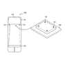
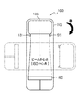
図1は、本発明の一実施形態による放射線治療機器100を示す図面であり、図2は、図1の放射線治療機器100を概略的に示した概念図である。
FIG. 1 is a view showing a
図1及び図2を参照すれば、本発明の一実施形態による放射線治療機器100は、本体部110、ガントリ120、放射線の照射ヘッド130、映像獲得部140、ベッド部150及び基準映像獲得用フレーム160を含む。それらについてさらに詳細に説明すれば、次の通りである。
1 and 2, a
放射線治療は、腫瘍に高線量放射線を集中照射して癌を治療する治療法である。成功を期す放射線治療のためには、周辺正常臓器の障害を最小化しながら、腫瘍に放射線を集中させる治療技術、精密な放射線治療機器、及び多様な映像確認装置が必ず必要である。 Radiotherapy is a treatment method that treats cancer by intensively irradiating a tumor with high-dose radiation. For successful radiotherapy, it is essential to have a treatment technique that concentrates radiation on the tumor, precise radiotherapy equipment, and various image confirmation devices while minimizing damage to surrounding normal organs.
最近、高精密放射線治療機器の普及が拡散しながら、高難度治療技術を利用した高線量の照射が普遍化されている。かような高線量の照射を介して腫瘍除去効率は向上したが、誤照射による潜在的放射線事故の危険も共に増大している。従って、最近、かような事故予防のために、治療機器の厳格な品質管理(quality assurance)を法で規定している。 Recently, the spread of high-precision radiotherapy equipment has spread, and high-dose irradiation using high-difficulty treatment technology has become universal. Tumor removal efficiency has improved through such high dose irradiation, but the risk of potential radiation accidents due to mis-irradiation has also increased. Therefore, recently, because of such a accident prevention, and strict quality control of treatment equipment (quality assurance) defined by law.
一方、電子ポータル映像装置(EPID:electronic portal imaging device)は、正確な治療を目的に、主に患者の治療姿勢確認のために使用されているが、最近、放射線治療機器の品質管理のための手段として使用するための試みが増加している。品質管理において、EPIDの使用は、既存方法と比較し、便利であって効率性の高いという長所があるが、EPIDの位置再現性が測定時ごとに異なるだけではなく、放射線治療機器のガントリ回転時、重力によるEPIDの位置変動が発生し、EPID映像を利用して、品質管理を行って映像を分析するのに多くの困難と制限とが存在した。それにより、EPIDを利用した品質管理遂行のためには、多様なガントリ角度で撮影した映像を補正することにより、EPID位置の誤差を除去し、位置誤差の正確度を改善するシステムが要求される。 On the other hand, an electronic portal imaging device (EPID) is used mainly for the confirmation of a patient's treatment posture for the purpose of accurate treatment. Recently, for the quality control of radiotherapy equipment. There are an increasing number of attempts to use as a means. In quality control, the use of EPID has the advantage that it is convenient and efficient compared to existing methods, but not only the position reproducibility of EPID differs from measurement to measurement, but also the gantry rotation of radiotherapy equipment At times, the position of the EPID changed due to gravity, and there were many difficulties and limitations in using the EPID video to perform quality control and analyze the video. As a result, in order to perform quality control using EPID, a system is required that corrects images taken at various gantry angles to remove EPID position errors and improve position error accuracy. .
本発明の一実施形態による放射線治療機器100は、ガントリ120の一側に、基準映像獲得用フレーム160を具備し、基準映像を獲得した後、それを利用して、分析用映像を分析することにより、EPIDのような映像獲得部140の位置変化によって発生する測定誤差を算出し、それを補正することを特徴とする。以下では、それについて、さらに詳細に説明する。
The
再び、図1及び図2を参照すれば、本体部110は、放射線治療機器100の基底部を
形成し、ガントリ120、放射線の照射ヘッド130及び映像獲得部140の回転基準に
なる。
Referring to FIGS. 1 and 2 again, the
ガントリ120は、本体部110の一側に結合し、本体部110に対して、少なくとも一方向に回転自在に形成される。このとき、ガントリ120の放射線の照射ヘッド130と対向するように形成される映像獲得部140が、ガントリ120と共に回転する。すなわち、ガントリ120、放射線の照射ヘッド130及び映像獲得部140が、図1の矢印A方向(または、その反対方向)に回転自在に形成されるのである。
The
ガントリ120の一側には、放射線を照射する放射線の照射ヘッド130が形成される。ここで、放射線の照射ヘッド130は、エックス線、ガンマ線、高エネルギー電子、高エネルギー陽性子、またはその他高エネルギー微粒子を放出することができる。
On one side of the
また、放射線の照射ヘッド130は、エックス線発生装置、放射線同位元素ソースまたは線形加速器のうちいずれか一つを含んでもよい。または、放射線の照射ヘッド130は、放射線治療機器100の外部に設けられた粒子加速器で加速させて生成した高エネルギー微粒子ビームを伝達されて放出することができる。または、放射線の照射ヘッド130は、多葉コリメータ(MLC:multi-leaf collimator)によって具現されてもよい。多葉コリメータを利用すれば、放射線の照射ヘッド130は、内部にビーム成形が可能であるので、さらに効率的な放射線エネルギー伝達が可能になる。
The
一方、放射線の照射ヘッド130から放射線が照射される方向に、フレーム装着ガイド131が突設され、かようなフレーム装着ガイド131に、基準映像獲得用フレーム160が結合されてもよい。
On the other hand, a
映像獲得部140は、一種のイメージセンサであり、放射線を検出し、それを電気的信号に変換して映像を獲得する装置である。かような映像獲得部140の一実施形態として電子ポータル映像装置(EPID)が使用されてもよい。詳細には、EPID技術は、高エネルギーの放射線を利用した放射線治療時、患者の患部位置確認のために、患者を透過した放射線を検出し、電気的信号に変換して映像を獲得する技術である。かような映像獲得部140は、後述する基準映像及び分析対象映像を獲得することができる。
The
ベッド部150は、患者が横になることができるように形成され、照射ヘッド130から照射される放射線に対してx軸方向、y軸方向、z軸方向に移動するように構成されてもよい。
The
基準映像獲得用フレーム160は、内部に開口部が形成された一種のウィンドウ形態に形成され、そのエッジ部分には、複数個のマーカー(marker)161が形成される。基準映像獲得用フレーム160は、放射線の照射ヘッド130のフレーム装着ガイド131に嵌め込まれた状態で、放射線の照射ヘッド130と固定結合される。
The reference
一方、図面には図示されていないが、本発明の一実施形態による放射線治療機器100は、位置誤差補正部(図示せず)をさらに具備することができる。位置誤差補正部(図示せず)は、所定のモータ、アクチュエータなどを含んでもよく、ガントリ120、放射線の照射ヘッド130、映像獲得部140のうち少なくとも一つに設けられ、ガントリ120、放射線の照射ヘッド130または映像獲得部140のx軸、y軸またはz軸に対して移動自在に形成される。かような位置誤補正部(図示せず)を具備し、位置誤差を補正することにより、放射線治療機器の品質管理を行うことができるのである。
Meanwhile, although not shown in the drawings, the
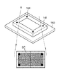
図4Aないし図4Dは、図1の放射線治療機器を利用して品質管理を行う過程を図示した図面である。 4A to 4D are views illustrating a process of performing quality control using the radiotherapy apparatus of FIG.
図4Aに図示されているように、放射線の照射ヘッド130の一側に、複数個のマーカー161が形成された基準映像獲得用フレーム160が配置された状態で、放射線の照射ヘッド130から放射線Rが照射され、前記複数個のマーカーが含まれた基準映像が獲得される。
As shown in FIG. 4A, the radiation image is emitted from the
このとき、放射線の照射ヘッド130から照射される放射線Rは、十分に広い領域に照射され、基準映像獲得用フレーム160の枠部に形成された複数個のマーカー161がいずれも基準映像内に含まれるようにする。
At this time, the radiation R irradiated from the
そして、かように獲得した基準映像から、ビーム中心点BC(beam center)を算出する。かようなビーム中心点BCは、例えば、基準映像に撮影された4つのマーカーの対角線の交差点からも算出され、または4つのマーカーが形成する長方形の横縦での中心点から算出することもでき、それ以外にも、多様な方法により、基準映像からビーム中心点BCを算出することができる。 Then, a beam center point BC (beam center) is calculated from the reference image acquired in this way. Such a beam center point BC can be calculated from, for example, the intersection of diagonal lines of four markers photographed in the reference image, or can be calculated from the horizontal and vertical center points of the rectangle formed by the four markers. In addition, the beam center point BC can be calculated from the reference image by various methods.
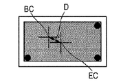
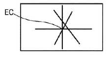
一方、この状態で、ガントリ120、放射線の照射ヘッド130及び映像獲得部140が本体部110を中心に一定角度回転し、このとき、映像獲得部140の自重などの要因によって、映像獲得部140の位置が変わりもする。すなわち、図3に図示されているように、ガントリ120、放射線の照射ヘッド130及び映像獲得部140が、本体部110を中心に、矢印B方向に回転する場合、映像獲得部140の自重によって、その位置が変わりもする。従って、図4Bに図示されているように、映像獲得部140自体の中心点ECと、基準映像から算出したビーム中心点BCとの間に、誤差Dが発生することもある。
On the other hand, in this state, the
かように、映像獲得部140の位置が一定程度変更された状態で、放射線の照射ヘッド130から、さまざまな角度で放射線が照射され、図4Cに図示されているような1以上の分析対象映像が獲得される。ここで、該分析対象映像は、放射線の照射ヘッド130が45゜回転するたびに獲得した映像でもあり、その場合、総8個の分析対象映像が獲得される。
In this way, with the position of the
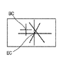
そのとき、映像獲得部140の位置が一定程度変更された状態であるために、映像獲得部140自体の中心点ECを基準に品質管理を行う場合、必然的に位置誤差が発生し、従って、精密な品質管理が行われないという問題点が存在する。従って、図4Dに図示されているように、本発明の一実施形態においては、映像獲得部140自体の中心点ECではない、基準映像から算出されたビーム中心点BCを基準に分析対象映像を分析し、品質管理を行うことにより、さらに正確であって信頼性高い品質管理を行うのである。
At that time, since the position of the
品質管理の一例として、前述の8個の分析対象映像でのビーム照射領域の中心点を算出し、かように算出された分析対象映像の中心点が、基準映像から算出されたビーム中心点BCを基準に、いかほど離隔されているかということを検査することができる。すなわち、分析対象映像の中心点が、基準映像から算出されたビーム中心点BCから所定距離(例えば、1mm)以内離隔されていれば、品質管理をパスしたものと判断し、前記所定距離より遠く離隔されている場合、品質管理をパスしていないと判断し、放射線治療機器100に対する所定の調整手続きを遂行することができる。かように、映像獲得部140自体の中心点ECではない、基準映像から算出されたビーム中心点BCを基準に、分析対象映像を分析して品質管理を行うことにより、さらに正確であって信頼性高い品質管理を行うのである。
As an example of quality control, the center point of the beam irradiation area in the above-described eight analysis target images is calculated, and the calculated center point of the analysis target image is the beam center point BC calculated from the reference image. It is possible to inspect how far they are separated from each other. That is, if the center point of the analysis target image is separated from the beam center point BC calculated from the reference image within a predetermined distance (for example, 1 mm), it is determined that the quality control is passed, and is farther than the predetermined distance. If they are separated from each other, it is determined that the quality control is not passed, and a predetermined adjustment procedure for the
さらに、ガントリ120、放射線の照射ヘッド130、映像獲得部140のうち少なくとも一つに設けられた位置誤差補正部(図示せず)を利用して、ガントリ120、放射線の照射ヘッド130または映像獲得部140を、x軸、y軸またはz軸に対して移動することにより、位置誤差を補正し、放射線治療機器の品質管理を行うこともできる。
Further, the position error correction unit (not shown) provided in at least one of the
かような本発明の実施形態による放射線治療機器によって、EPIDの位置変化によって発生する誤差を算出し、それを補正するという効果を得ることができる。また、EPIDを利用して、正確/精密な品質管理が可能であり、デジタル映像を利用するので、正確度向上が可能になるという効果を得ることができる。さらには、EPIDを利用することにより、従来の放射線用フィルムを使用せずとも、フィルム使用によるコストを節減するという効果を得ることができる。また、かようにEPIDを利用することにより、自動化された品質管理が可能であり、また品質管理に必要となる時間、コスト、人力を節減するという効果を得ることができる。 With such a radiotherapy device according to the embodiment of the present invention, it is possible to obtain an effect of calculating an error caused by a change in position of the EPID and correcting it. Further, accurate / precise quality control can be performed using EPID, and since digital video is used, the effect of improving accuracy can be obtained. Furthermore, by using EPID, it is possible to obtain an effect of reducing the cost of using the film without using a conventional radiation film. In addition, by using the EPID in this way, it is possible to perform automated quality control, and it is possible to obtain an effect of saving time, cost, and manpower required for quality management.
以下では、本発明の一実施形態による放射線治療機器の品質管理方法について説明する。 Below, the quality control method of the radiotherapy apparatus by one Embodiment of this invention is demonstrated.
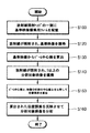
図5は、本発明の一実施形態による放射線治療機器の品質管理方法を示すフローチャートである。図5を参照すれば、放射線の照射ヘッドの一側に、複数個のマーカーが形成された基準映像獲得用フレームが配置される段階(S110段階)、前記放射線の照射ヘッドから放射線が照射され、前記複数個のマーカーが含まれた基準映像が獲得される段階(S120段階)、前記基準映像からビーム中心点が算出される段階(S130段階)、前記放射線の照射ヘッドから放射線が照射され、1以上の分析対象映像が獲得される段階(S140段階)、前記基準映像から算出されたビーム中心点と、前記EPIDの中心点とを比較し、前記映像獲得部の位置誤差が算出される段階(S150段階)、前記算出された位置誤差を反映させ、前記分析対象映像を分析する段階(S160段階)を含む。 FIG. 5 is a flowchart illustrating a quality control method for a radiation therapy apparatus according to an embodiment of the present invention. Referring to FIG. 5, a step of arranging a reference image acquisition frame having a plurality of markers on one side of the radiation irradiation head (S110), radiation is emitted from the radiation irradiation head, A step of obtaining a reference image including the plurality of markers (step S120), a step of calculating a beam center point from the reference image (step S130), and radiation irradiated from the radiation irradiation head. The above-described analysis target image is acquired (S140), the beam center point calculated from the reference image is compared with the EPID center point, and the position error of the image acquisition unit is calculated ( Step S150) includes analyzing the image to be analyzed by reflecting the calculated position error (Step S160).
まず、放射線の照射ヘッドの一側に、複数個のマーカーが形成された基準映像獲得用フレームを配置する(S110段階)。詳細には、基準映像獲得用フレーム160は、内部に開口部が形成された一種のウィンドウ形態に形成され、そのエッジ部分には、複数個のマーカー161が形成される。基準映像獲得用フレーム160は、放射線の照射ヘッド130のフレーム装着ガイド131に嵌め込まれた状態で、放射線の照射ヘッド130と固定結合される。
First, a reference image acquisition frame having a plurality of markers is disposed on one side of a radiation irradiation head (step S110). Specifically, the reference
次に、放射線の照射ヘッドから放射線が照射され、前記複数個のマーカーが含まれた基準映像が獲得される(S120段階)。すなわち、放射線の照射ヘッド130の一側に、複数個のマーカー161が形成された基準映像獲得用フレーム160が配置された状態で、放射線の照射ヘッド130から放射線Rが照射され、前記複数個のマーカーが含まれた基準映像が獲得される。そのとき、放射線の照射ヘッド130から照射される放射線Rは、十分に広い領域に照射され、基準映像獲得用フレーム160の枠部に形成された複数個のマーカー161がいずれも基準映像内に含まれるようになる。
Next, radiation is irradiated from the radiation irradiation head, and a reference image including the plurality of markers is acquired (step S120). That is, the radiation R is irradiated from the
次に、基準映像から、ビーム中心点が算出される(S130段階)。かようなビーム中心点BCは、例えば、基準映像に撮影された4つのマーカーの対角線の交差点からも算出され、または4つのマーカーが形成する長方形の横縦での中心点からも算出され、それ以外にも、多様な方法で、基準映像からビーム中心点BCを算出することができる。 Next, a beam center point is calculated from the reference image (step S130). Such a beam center point BC is calculated from, for example, the intersection of diagonal lines of four markers photographed in the reference image, or from the center point of the rectangle formed by the four markers. In addition, the beam center point BC can be calculated from the reference image by various methods.
次に、前記放射線の照射ヘッドから放射線が照射され、1以上の分析対象映像が獲得される(S140段階)。例えば、分析対象映像は、放射線の照射ヘッド130が45゜回転するたびに獲得した映像でもあり、その場合、総8個の分析対象映像が獲得される。
Next, radiation is emitted from the radiation irradiation head, and one or more analysis target images are acquired (step S140). For example, the analysis target image is also an image acquired every time the
次に、前記基準映像から算出されたビーム中心点、と前記EPIDの中心点とを比較し、前記映像獲得部の位置誤差を算出し(S150段階)、前記算出された位置誤差を反映させ、前記分析対象映像を分析する(S160段階)。 Next, the beam center point calculated from the reference image is compared with the center point of the EPID, the position error of the image acquisition unit is calculated (S150), and the calculated position error is reflected, The analysis target image is analyzed (S160).
例えば、前述の8個の分析対象映像でのビームの照射領域の中心点を算出し、かように算出された分析対象映像の中心点が、基準映像から算出されたビーム中心点BCを基準に、いかほど離隔されているかということを検査することができる。すなわち、分析対象映像の中心点が、基準映像から算出されたビーム中心点BCから所定距離(例えば、1mm)以内離隔されているのであるならば、品質管理をパスしたものであると判断し、前記所定距離より遠く離隔されている場合、品質管理をパスしていないと判断し、放射線治療機器100に対する所定の調整手続きを遂行する。かように、映像獲得部140自体の中心点ECではない、基準映像から算出されたビーム中心点BCを基準に、分析対象映像を分析して品質管理を行うことにより、さらに正確であって信頼性高い品質管理を行うのである。
For example, the center point of the irradiation region of the beam in the above-described eight analysis target images is calculated, and the center point of the analysis target image thus calculated is based on the beam center point BC calculated from the reference image. You can test how far away they are. That is, if the center point of the analysis target image is separated from the beam center point BC calculated from the reference image within a predetermined distance (for example, 1 mm), it is determined that the quality control is passed, If the distance is greater than the predetermined distance, it is determined that the quality control is not passed, and a predetermined adjustment procedure for the
さらに、図面には図示されていないが、ガントリ120、放射線の照射ヘッド130、映像獲得部140のうち少なくとも1つの位置誤差を補正する段階をさらに含んでもよい。すなわち、ガントリ120、放射線の照射ヘッド130、映像獲得部140のうち少なくとも一つに設けられた位置誤差補正部(図示せず)を利用して、ガントリ120、放射線の照射ヘッド130または映像獲得部140を、x軸、y軸またはz軸に対して移動することにより、位置誤差を補正し、放射線治療機器の品質管理を行うこともできる。
Further, although not shown in the drawing, it may further include a step of correcting a position error of at least one of the
かような本発明の実施形態による放射線治療機器によって、EPIDの位置変化によって発生する誤差を算出し、それを補正するという効果を得ることができる。また、EPIDを利用して、正確/精密な品質管理が可能であり、デジタル映像を利用するので、正確度向上が可能になるという効果を得ることができる。さらには、EPIDを利用することにより、従来の放射線用フィルムを使用しなくともよく、フィルム使用によるコスト節減という効果を得ることができる。また、かようにEPIDを利用することにより、自動化された品質管理が可能であり、また品質管理に必要となる時間、コスト、人力を節減するという効果を得ることができる。 With such a radiotherapy device according to the embodiment of the present invention, it is possible to obtain an effect of calculating an error caused by a change in position of the EPID and correcting it. Further, accurate / precise quality control can be performed using EPID, and since digital video is used, the effect of improving accuracy can be obtained. Furthermore, by using EPID, it is not necessary to use a conventional film for radiation, and an effect of cost reduction by using the film can be obtained. In addition, by using the EPID in this way, it is possible to perform automated quality control, and it is possible to obtain an effect of saving time, cost, and manpower required for quality management.
かように、本発明は図面に図示された一実施形態を参照して説明したが、それらは、例示的なものに過ぎず、当該分野で当業者であるならば、それらから多様な変形、及び実施形態の変形が可能であるという点を理解するであろう。従って、本発明の真の技術的保護範囲は、特許請求の範囲の技術的思想によって決められるものである。 Thus, although the present invention has been described with reference to one embodiment illustrated in the drawings, they are merely exemplary and various modifications will occur to those of ordinary skill in the art. It will be understood that variations of the embodiments are possible. Therefore, the true technical protection scope of the present invention is determined by the technical idea of the claims.
本発明の実施形態は、放射線治療機器、及び放射線治療機器の品質管理方法に利用される。 Embodiments of the present invention are used in a radiotherapy device and a quality control method for the radiotherapy device.
Claims (9)
前記本体部の一側に結合し、前記本体部に対して、少なくとも一方向に回転自在に形成されるガントリと、
前記ガントリの一側に形成されて放射線を照射する放射線の照射ヘッドと、
前記放射線の照射ヘッドと対向するように形成され、前記放射線の照射ヘッドから照射される放射線を検出し、それを電気的信号に変換して映像を獲得する映像獲得部と、
前記放射線の照射ヘッドの一側に形成されて複数個のマーカーが形成された基準映像獲得用フレームと、を含み、
前記映像獲得部は、
複数個の前記マーカーが含まれた基準映像と、1以上の分析対象映像と、を獲得し、
前記基準映像から算出されたビーム中心点と、前記映像獲得部の中心点と、を比較し、前記映像獲得部の位置誤差を算出し、
前記算出された位置誤差を反映させ、前記分析対象映像を分析し、
ここで、前記分析は、前記分析対象映像の中心点が、前記基準映像から算出されたビーム中心点BCを基準に、いかほど離隔されているかということに基づいて分析することを特徴とする放射線治療機器。 The main body,
A gantry that is coupled to one side of the main body and is formed to be rotatable in at least one direction with respect to the main body.
A radiation irradiation head that is formed on one side of the gantry and emits radiation;
A video acquisition unit that is formed so as to face the radiation irradiation head, detects radiation irradiated from the radiation irradiation head, converts it into an electrical signal, and acquires an image;
And a plurality of reference image acquisition frame the marker is formed is formed on one side of the irradiation head of the radiation observed including,
The video acquisition unit
Obtaining a reference image including a plurality of the markers and one or more analysis target images;
The beam center point calculated from the reference image is compared with the center point of the image acquisition unit, and the position error of the image acquisition unit is calculated.
Reflecting the calculated position error, analyzing the analysis target video,
Here, the analysis is performed based on how far the center point of the analysis target image is separated with reference to the beam center point BC calculated from the reference image. machine.
前記放射線の照射ヘッドから放射線が照射され、前記複数個のマーカーが含まれた基準映像が獲得される段階と、
前記基準映像からビーム中心点が算出される段階と、
前記放射線の照射ヘッドから放射線が照射され、1以上の分析対象映像が獲得される段階と、
前記基準映像から算出されたビーム中心点を基準に、前記分析対象映像が分析される段階と、を含み、
前記基準映像から算出されたビーム中心点を基準に、前記分析対象映像が分析される段階は、
前記基準映像から算出されたビーム中心点と、前記映像獲得部の中心点と、を比較し、前記映像獲得部の位置誤差が算出される段階と、
前記算出された位置誤差を反映させ、前記分析対象映像を分析する段階と、を含み、
前記算出された位置誤差を反映させ、前記分析対象映像を分析する段階は、
前記分析対象映像の中心点が、前記基準映像から算出されたビーム中心点BCを基準に、いかほど離隔されているかということに基づいて分析することを特徴とする放射線治療機器の品質管理方法。 A step of arranging a reference image acquisition frame in which a plurality of markers are formed on one side of the radiation irradiation head;
Radiation is irradiated from the radiation irradiation head, and a reference image including the plurality of markers is acquired;
Calculating a beam center point from the reference image;
Radiation is emitted from the radiation irradiation head, and one or more analysis target images are acquired; and
Relative to the beam center points calculated from the reference image, the method comprising the analyte image is analyzed, only including,
Analyzing the analysis target image based on the beam center point calculated from the reference image,
Comparing a beam center point calculated from the reference image with a center point of the image acquisition unit, and calculating a position error of the image acquisition unit;
Reflecting the calculated position error and analyzing the analysis target image,
Reflecting the calculated position error and analyzing the analysis target video,
A quality control method for a radiotherapy device, wherein analysis is performed based on how far a center point of the analysis target image is separated with reference to a beam center point BC calculated from the reference image .
前記複数個のマーカーがいずれも基準映像に含まれるように前記放射線が照射されることを特徴とする請求項6に記載の放射線治療機器の品質管理方法。 The step of irradiating radiation from the radiation irradiation head and obtaining a reference image including the plurality of markers includes:
The quality control method for a radiation therapy apparatus according to claim 6 , wherein the radiation is irradiated so that the plurality of markers are all included in a reference image.
Applications Claiming Priority (3)
| Application Number | Priority Date | Filing Date | Title |
|---|---|---|---|
| KR1020140091325A KR102117680B1 (en) | 2014-07-18 | 2014-07-18 | Device for radiotherapy and method for quality assurance for the same |
| KR10-2014-0091325 | 2014-07-18 | ||
| PCT/KR2015/007456 WO2016010398A1 (en) | 2014-07-18 | 2015-07-17 | Radiation therapy device and quality control method for radiation therapy device |
Publications (3)
| Publication Number | Publication Date |
|---|---|
| JP2017516579A JP2017516579A (en) | 2017-06-22 |
| JP2017516579A5 JP2017516579A5 (en) | 2018-05-10 |
| JP6401302B2 true JP6401302B2 (en) | 2018-10-10 |
Family
ID=55078801
Family Applications (1)
| Application Number | Title | Priority Date | Filing Date |
|---|---|---|---|
| JP2016570337A Active JP6401302B2 (en) | 2014-07-18 | 2015-07-17 | Radiotherapy device and quality control method of radiotherapy device |
Country Status (5)
| Country | Link |
|---|---|
| US (1) | US10449385B2 (en) |
| EP (1) | EP3170532B1 (en) |
| JP (1) | JP6401302B2 (en) |
| KR (1) | KR102117680B1 (en) |
| WO (1) | WO2016010398A1 (en) |
Families Citing this family (8)
| Publication number | Priority date | Publication date | Assignee | Title |
|---|---|---|---|---|
| JP6503657B2 (en) * | 2014-08-08 | 2019-04-24 | ユーハ味覚糖株式会社 | Gumi candy with high moisture content |
| KR101872226B1 (en) * | 2016-11-07 | 2018-06-28 | 사회복지법인 삼성생명공익재단 | Calibration unit, apparatus for radiotherapy and calibration method thereof |
| US10201719B2 (en) * | 2017-03-30 | 2019-02-12 | Varian Medical Systems Particle Therapy Gmbh | Gantry system for particle beam therapy |
| KR102118674B1 (en) * | 2018-01-05 | 2020-06-04 | 한국기계연구원 | Video guidance system for supporting localization of mobile c-arm fluoroscopy and method for locating the position of mobile c-arm fluoroscopy using the same |
| CN108578905A (en) * | 2018-01-26 | 2018-09-28 | 合肥驼峰电子科技发展有限公司 | A kind of annular illumination head of MM wave therapeutic instrument |
| CA3125971A1 (en) * | 2019-01-07 | 2020-07-16 | University Of Kentucky Research Foundation | Quality assurance device with passive optical component and remote camera |
| KR102219338B1 (en) * | 2019-04-11 | 2021-02-23 | 사회복지법인 삼성생명공익재단 | System and method for quality assurance of three-dimensional isocenter of radiation diagnosis and treatment device |
| CN117889789B (en) * | 2024-03-15 | 2024-06-04 | 浙江建投数字技术有限公司 | Building wall flatness detection method and system |
Family Cites Families (13)
| Publication number | Priority date | Publication date | Assignee | Title |
|---|---|---|---|---|
| JP3625871B2 (en) * | 1994-10-19 | 2005-03-02 | ジーイー横河メディカルシステム株式会社 | Medical device having radiation treatment planning function |
| US6260999B1 (en) | 1999-07-26 | 2001-07-17 | Siemens Medical Systems, Inc. | Isocenter localization using electronic portal imaging |
| JP2002272862A (en) | 2001-03-19 | 2002-09-24 | Mitsubishi Electric Corp | Radiation medical treating instrument |
| SE522162C2 (en) | 2002-05-06 | 2004-01-20 | Goergen Nilsson | Dose delivery quantification enabling method for radiotherapy treatment, involves analyzing measurements to obtain information about relation between measurements in phantom and information between phantom and treatment source |
| KR101164150B1 (en) * | 2003-08-12 | 2012-07-13 | 로마 린다 유니버시티 메디칼 센터 | Patient positioning system for radiation therapy system |
| RU2360716C2 (en) | 2003-08-12 | 2009-07-10 | Лома Линда Юниверсити Медикал Сентер | Patient-aid modular system |
| EP2116278A1 (en) | 2008-05-06 | 2009-11-11 | Ion Beam Applications S.A. | Device for 3D dose tracking in radiation therapy |
| KR101007367B1 (en) | 2008-06-18 | 2011-01-13 | 사회복지법인 삼성생명공익재단 | System and method for controlling medical treatment machine |
| JP2010183976A (en) * | 2009-02-10 | 2010-08-26 | Mitsubishi Heavy Ind Ltd | Radiotherapy apparatus controller and irradiation method |
| US8235594B2 (en) | 2009-11-02 | 2012-08-07 | Carn Ronald M | Alignment fixture for X-ray images |
| KR20120097855A (en) * | 2011-02-25 | 2012-09-05 | 대니비엠티 주식회사 | Non-invasive and fractionational gamma knife immobilization system and mask fixed position correcting method thereof |
| KR101341288B1 (en) | 2013-10-24 | 2013-12-12 | 사회복지법인 삼성생명공익재단 | Quality assurance system and the method for radiotherapy apparatus |
| FR3021545A1 (en) * | 2014-06-03 | 2015-12-04 | Qualiformed | OBJECT-TEST FOR CORRECTION OF PARASITE OUTPUT IMAGER MOVEMENTS EQUIPPED WITH EXTERNAL RADIOTHERAPY TREATMENT APPARATUS WHEN THE DEVICE IS IN MOTION |
-
2014
- 2014-07-18 KR KR1020140091325A patent/KR102117680B1/en active IP Right Grant
-
2015
- 2015-07-17 EP EP15822272.9A patent/EP3170532B1/en active Active
- 2015-07-17 US US15/315,093 patent/US10449385B2/en active Active
- 2015-07-17 JP JP2016570337A patent/JP6401302B2/en active Active
- 2015-07-17 WO PCT/KR2015/007456 patent/WO2016010398A1/en active Application Filing
Also Published As
| Publication number | Publication date |
|---|---|
| KR20160010223A (en) | 2016-01-27 |
| EP3170532A1 (en) | 2017-05-24 |
| US10449385B2 (en) | 2019-10-22 |
| EP3170532B1 (en) | 2022-04-06 |
| KR102117680B1 (en) | 2020-06-01 |
| EP3170532A4 (en) | 2018-02-28 |
| WO2016010398A1 (en) | 2016-01-21 |
| JP2017516579A (en) | 2017-06-22 |
| US20170197091A1 (en) | 2017-07-13 |
Similar Documents
| Publication | Publication Date | Title |
|---|---|---|
| JP6401302B2 (en) | Radiotherapy device and quality control method of radiotherapy device | |
| JP2017516579A5 (en) | ||
| US11247072B2 (en) | X-ray imaging system with a combined filter and collimator positioning mechanism | |
| EP1960051B1 (en) | Device and method for positioning a target volume in a radiation therapy apparatus | |
| US9968321B2 (en) | Method and imaging system for determining a reference radiograph for a later use in radiation therapy | |
| US20060182326A1 (en) | Radiation therapy method with target detection | |
| JP5329256B2 (en) | Bed positioning system, radiation therapy system, and bed positioning method | |
| US20130229495A1 (en) | Method for calibrating an imaging system | |
| KR101678681B1 (en) | Device for radiotherapy and method for quality assurance for the same | |
| KR102068326B1 (en) | Radiation therapy apparatus for animals | |
| JP6465283B2 (en) | Radiation therapy system | |
| CN107693958B (en) | Method for verifying whole course position of radiotherapy | |
| KR101872226B1 (en) | Calibration unit, apparatus for radiotherapy and calibration method thereof | |
| KR102080162B1 (en) | Device for radiotherapy and method for quality assurance for the same | |
| CN110678225B (en) | Patient irradiation treatment plan verification system | |
| US20110309242A1 (en) | Radiation-activated Fiducial Markers for Organ Tracking | |
| Parodi | Imaging in Radiotherapy | |
| JP2022069797A (en) | Radiation therapy equipment and radiation therapy method | |
| JP2023023437A (en) | Particle beam care system and treatment planning device | |
| CN118369139A (en) | Position verification and correction for radiation therapy using non-orthogonal on-board imaging | |
| JP2021027848A (en) | Neutron capture therapy system | |
| JP2008237714A (en) | Radiation therapy system |
Legal Events
| Date | Code | Title | Description |
|---|---|---|---|
| A621 | Written request for application examination |
Free format text: JAPANESE INTERMEDIATE CODE: A621 Effective date: 20161130 |
|
| A977 | Report on retrieval |
Free format text: JAPANESE INTERMEDIATE CODE: A971007 Effective date: 20171012 |
|
| A131 | Notification of reasons for refusal |
Free format text: JAPANESE INTERMEDIATE CODE: A131 Effective date: 20171020 |
|
| A601 | Written request for extension of time |
Free format text: JAPANESE INTERMEDIATE CODE: A601 Effective date: 20180118 |
|
| A524 | Written submission of copy of amendment under article 19 pct |
Free format text: JAPANESE INTERMEDIATE CODE: A524 Effective date: 20180320 |
|
| TRDD | Decision of grant or rejection written | ||
| A01 | Written decision to grant a patent or to grant a registration (utility model) |
Free format text: JAPANESE INTERMEDIATE CODE: A01 Effective date: 20180829 |
|
| A61 | First payment of annual fees (during grant procedure) |
Free format text: JAPANESE INTERMEDIATE CODE: A61 Effective date: 20180906 |
|
| R150 | Certificate of patent or registration of utility model |
Ref document number: 6401302 Country of ref document: JP Free format text: JAPANESE INTERMEDIATE CODE: R150 |
|
| R250 | Receipt of annual fees |
Free format text: JAPANESE INTERMEDIATE CODE: R250 |
|
| R250 | Receipt of annual fees |
Free format text: JAPANESE INTERMEDIATE CODE: R250 |
|
| R250 | Receipt of annual fees |
Free format text: JAPANESE INTERMEDIATE CODE: R250 |
|
| R250 | Receipt of annual fees |
Free format text: JAPANESE INTERMEDIATE CODE: R250 |