JP6400330B2 - Sliding parts and manufacturing method thereof - Google Patents
Sliding parts and manufacturing method thereof Download PDFInfo
- Publication number
- JP6400330B2 JP6400330B2 JP2014102279A JP2014102279A JP6400330B2 JP 6400330 B2 JP6400330 B2 JP 6400330B2 JP 2014102279 A JP2014102279 A JP 2014102279A JP 2014102279 A JP2014102279 A JP 2014102279A JP 6400330 B2 JP6400330 B2 JP 6400330B2
- Authority
- JP
- Japan
- Prior art keywords
- sliding
- solid lubricant
- intermediate layer
- lubricant particles
- layer
- Prior art date
- Legal status (The legal status is an assumption and is not a legal conclusion. Google has not performed a legal analysis and makes no representation as to the accuracy of the status listed.)
- Active
Links
Images


Description
本発明は、油圧ポンプなどの流体圧駆動機器の一部を構成する摺動部品およびその製造方法に関するものである。 The present invention relates to a sliding component that constitutes a part of a fluid pressure driving device such as a hydraulic pump and a method for manufacturing the same.
自動車や産業機械などに用いられている流体圧駆動機器には省エネルギー化を目的とした駆動流体の低粘度化が進められている。そのため、この流体圧駆動機器を構成する摺動部品の摺動面には、摺動面間の摩擦抵抗の低減および焼付き損傷防止のための潤滑表面処理として、例えばその摺動面上に固体潤滑剤を定着させる方法が提案されている。 In fluid pressure drive devices used in automobiles and industrial machines, the viscosity of drive fluids is being reduced to save energy. For this reason, the sliding surfaces of the sliding parts constituting this fluid pressure drive device are applied with a lubrication surface treatment for reducing frictional resistance between the sliding surfaces and preventing seizure damage. A method for fixing a lubricant has been proposed.
固体潤滑剤を摺動面上に定着させる方法としては、例えば以下の特許文献1では、摺動面を構成する基材上に低融点合金と熱伝導性フィラーと中間層用耐熱樹脂との混合物からなる樹脂中間層を形成した後、この樹脂中間層上に、固体潤滑剤と表面層用耐熱性樹脂との混合物からなる固体潤滑剤表面層を形成することで固体潤滑剤を摺動面上に定着させている。 As a method for fixing a solid lubricant on a sliding surface, for example, in Patent Document 1 below, a mixture of a low melting point alloy, a heat conductive filler, and a heat resistant resin for an intermediate layer is formed on a base material constituting the sliding surface. After forming the resin intermediate layer, the solid lubricant is formed on the sliding surface by forming a solid lubricant surface layer composed of a mixture of the solid lubricant and the heat-resistant resin for the surface layer on the resin intermediate layer. Has been established.
また、中間層を用いないで固体潤滑剤を定着させる方法としては、例えば以下の特許文献2では、摺動面を構成する基材表面に対して固体潤滑剤粒子を圧縮空気流によって高速噴射して基材表層組織と衝突固体潤滑粒子との混合組織を形成し、さらに、その上に固体潤滑剤粒子の付着被覆層を形成している。 Further, as a method for fixing a solid lubricant without using an intermediate layer, for example, in Patent Document 2 below, solid lubricant particles are jetted at a high speed by a compressed air flow onto the surface of a base material constituting a sliding surface. Thus, a mixed structure of the substrate surface structure and the collision solid lubricant particles is formed, and an adhesion coating layer of the solid lubricant particles is further formed thereon.
特許文献1の方法によると、摺動面最表層の固体潤滑表面層によって摺接面上に固体潤滑剤が保持され、さらに熱伝導性に優れる中間層によって摺動熱を速やかに拡散させることで摺動面の耐焼付性と耐摩耗性を向上させることができるとしている。 According to the method of Patent Document 1, the solid lubricant is held on the sliding contact surface by the solid lubricating surface layer on the outermost surface of the sliding surface, and the sliding heat is quickly diffused by the intermediate layer having excellent thermal conductivity. The seizure resistance and wear resistance of the sliding surface can be improved.
しかし、樹脂バインダによって固体潤滑材を保持しているため、摺動熱の放散性が良好とはいえず、中間層としては低融点合金および熱伝導性フィラーを含有させた層を設けなければならず、その摺動面構造は異種材の多層積層構造となることから、剥離破壊の起点となる接合境界が複数存在するものとなってしまう。 However, since the solid lubricant is held by the resin binder, it cannot be said that the heat dissipation property is good, and the intermediate layer must be provided with a layer containing a low melting point alloy and a heat conductive filler. However, since the sliding surface structure is a multi-layered structure of dissimilar materials, there are a plurality of joining boundaries that are the starting points of peeling failure.
一方、特許文献2の方法によると、基材表層組織と衝突固体潤滑剤粒子との混合組織が形成されることで単純に基材表面を固体潤滑材で被覆した場合に比べ、固体潤滑効果が長期的に接続するとしている。 On the other hand, according to the method of Patent Document 2, a solid lubrication effect can be obtained as compared with a case where the substrate surface is simply covered with a solid lubricant by forming a mixed structure of the substrate surface layer structure and the collision solid lubricant particles. It is supposed to be connected in the long term.
しかし、摺動面を構成する基材がアルミニウム合金や銅合金などの比較的軟質な非鉄合金材であれば、前記のような効果を見込めるが、摺動面の構成材質が鉄鋼材などの硬質材である場合、軟質だったり、劈開性が高い構造であったりすることが多い固体潤滑粒子の衝突だけでは前記のような混合組織を形成させることが難しく、単純に基材表面を固体潤滑材で被覆した場合と比べて効果の持続性は変わらなくなってしまうことから、摺動面上に簡素な方法で固体潤滑材を保持させると同時に、長期的な固体潤滑効果を持続させるための摺動面構造およびその製造方法が必要とされている。 However, if the base material composing the sliding surface is a relatively soft non-ferrous alloy material such as an aluminum alloy or a copper alloy, the above effect can be expected, but the constituent material of the sliding surface is a hard material such as a steel material. In the case of a material, it is difficult to form a mixed structure as described above only by the collision of solid lubricant particles, which are often soft or have a structure with high cleaving property. Since the durability of the effect will not change compared to the case where it is coated with, the solid lubricant is held on the sliding surface by a simple method and at the same time, the sliding to maintain the long-term solid lubricating effect There is a need for a surface structure and a method of manufacturing the same.
そこで、本発明はこれらの課題を解決するために案出されたものであり、その目的は、摺動面の剥離破壊リスクを抑え、優れた潤滑性能を長期に亘って持続できる新規な摺動部品およびその製造方法を提供するものである。 Accordingly, the present invention has been devised to solve these problems, and the purpose thereof is a novel sliding that can suppress the risk of peeling fracture of the sliding surface and can maintain excellent lubrication performance over a long period of time. A component and a manufacturing method thereof are provided.
前記課題を解決するために第1の発明は、摺動面を構成する基材上に、前記基材とは異なる材質の中間層を有すると共に、前記中間層の表層に、固体潤滑材からなる表面層を有し、前記表面層は、前記中間層の表面に固体潤滑材粒子を配置した後、ローラバニシングまたはその他の転圧加工手段によって前記中間層の表層に埋没するようにして形成されていることを特徴とする摺動部品である。 In order to solve the above problems, the first invention has an intermediate layer made of a material different from the base material on the base material constituting the sliding surface, and a solid lubricant is formed on the surface layer of the intermediate layer. A surface layer, and the surface layer is formed so as to be buried in the surface layer of the intermediate layer by roller burnishing or other rolling means after disposing solid lubricant particles on the surface of the intermediate layer. It is a sliding part characterized by having.
このよう構成によれば、固体潤滑材からなる表面層が、固体潤滑材粒子を高圧で中間層の表層に埋没させることで形成されているため、表面層と中間層とが一体となるように強固に連結され、その接合界面での剥離破壊リスクを抑制できる。これによって、摺動面の耐焼付性や耐摩耗性が大幅に向上する。 According to such a configuration, since the surface layer made of the solid lubricant is formed by burying the solid lubricant particles in the surface layer of the intermediate layer at a high pressure, the surface layer and the intermediate layer are integrated. It is firmly connected, and the risk of debonding failure at the joint interface can be suppressed. This greatly improves the seizure resistance and wear resistance of the sliding surface.
第2の発明は、第1の発明において、前記中間層を構成する材質の硬度が、前記基材の硬度よりも低いことを特徴とする摺動部品である。このような構成によれば、基材が鉄鋼のように高硬度の材質であっても、軟質または高劈開性の固体潤滑材粒子を摺動面上に埋没させて保持することができる。 A second invention is the sliding component according to the first invention, wherein the hardness of the material constituting the intermediate layer is lower than the hardness of the base material. According to such a configuration, even if the base material is a high-hardness material such as steel, the soft or high-cleavage solid lubricant particles can be buried and held on the sliding surface.
第3の発明は、第2の発明において、前記基材が鉄を主体とする材質からなると共に、前記中間層が銅、スズ、亜鉛のいずれかまたはそれら2種類以上の混合物からなることを特徴とする摺動部品である。このような構成によれば、摺動面を構成する基材が鉄鋼などのように高硬度の材料であっても、中間層をこれより低硬度の銅やスズなどで構成することにより、軟質または高劈開性の固体潤滑材粒子を摺動面上に埋没させて保持することができる。 According to a third invention, in the second invention, the base material is made of a material mainly composed of iron, and the intermediate layer is made of copper, tin, zinc, or a mixture of two or more of them. It is a sliding part. According to such a configuration, even if the base material constituting the sliding surface is a high hardness material such as steel, the intermediate layer is made of softer copper, tin, etc. Alternatively, highly-cleavable solid lubricant particles can be buried and held on the sliding surface.
第4の発明は、第1乃至第3の発明において、前記表面層を構成する固体潤滑材粒子が、層状分子からなると共に、その層状分子の滑り面が摺動方向と平行になるように配向されていることを特徴とする摺動部品である。このような構成によれば、摺動面の初期摩耗を伴う摺動なじみ面を形成する必要がなく、摺動初期から摺動面の低摩擦化を達成することができる。 According to a fourth invention, in the first to third inventions, the solid lubricant particles constituting the surface layer are composed of layered molecules, and the sliding surfaces of the layered molecules are oriented in parallel with the sliding direction. It is a sliding component characterized by being made. According to such a configuration, it is not necessary to form a sliding conforming surface accompanied by initial wear of the sliding surface, and a reduction in friction of the sliding surface can be achieved from the initial sliding state.
第5の発明は、前記表面層を構成する固体潤滑材粒子が、二硫化モリブデンであることを特徴とする摺動部品である。二硫化モリブデンは、層状分子構造を有し、ローラバニシングまたはその他の転圧加工手段による平滑化処理(埋没処理)によってその層状分子の滑り面が自然と摺動面と平行になるように配向される。これにより、摺動面の初期摩耗を伴う摺動なじみ面形成を要することなく、摺動初期から摺動面の低摩擦化を達成することができる。 According to a fifth aspect of the present invention, there is provided a sliding component characterized in that the solid lubricant particles constituting the surface layer are molybdenum disulfide. Molybdenum disulfide has a layered molecular structure and is oriented so that the sliding surface of the layered molecule is naturally parallel to the sliding surface by roller burnishing or other smoothing treatment (embedding treatment). The Thereby, low friction of the sliding surface can be achieved from the beginning of sliding without requiring the formation of a sliding conforming surface with initial wear of the sliding surface.
第6の発明は、前記基材表面上に、前記中間層の厚さよりも深い凹部が複数形成されていることを特徴とする摺動部品である。このような構成によれば、転圧加工に際し、凹部には固体潤滑材粒子が押し込まれ、固められて圧縮充填部となり、凹部がない平坦部分にはその表層に固体潤滑材粒子が埋没するようにして平滑化される。これにより、その摺動面に十分な固体潤滑材を供給することができ、長期に亘って優れた潤滑性能を発揮できる。 A sixth invention is a sliding component characterized in that a plurality of recesses deeper than the thickness of the intermediate layer are formed on the surface of the base material. According to such a configuration, during the rolling process, the solid lubricant particles are pushed into the recesses and hardened to become a compression filling portion, and the solid lubricant particles are buried in the surface layer in a flat portion having no recesses. To be smoothed. Thereby, sufficient solid lubricant can be supplied to the sliding surface, and excellent lubrication performance can be exhibited over a long period of time.
第7の発明は、摺動面を構成する基材表面上に、前記基材とは異なる材質の中間層を形成し、前記中間層の表面に、固体潤滑材粒子を配置した後、ローラバニシングまたはその他の転圧加工手段によって前記固体潤滑材粒子を前記中間層の表層に埋没させるように平滑化して固体潤滑材からなる表面層を形成することを特徴とする摺動部品の製造方法である。このような製造方法によれば、表面層と中間層との接合界面での剥離破壊リスクが低い摺動部品を容易に製造できる。 According to a seventh aspect of the invention, an intermediate layer made of a material different from the base material is formed on the surface of the base material constituting the sliding surface, and solid lubricant particles are arranged on the surface of the intermediate layer, and then roller burnishing Or a method of manufacturing a sliding component, characterized in that a surface layer made of a solid lubricant is formed by smoothing the solid lubricant particles so as to be buried in a surface layer of the intermediate layer by other rolling compaction processing means. . According to such a manufacturing method, it is possible to easily manufacture a sliding component having a low risk of peeling failure at the bonding interface between the surface layer and the intermediate layer.
本発明の摺動部品によれば、固体潤滑材からなる表面層が、固体潤滑材粒子を高圧で中間層の表層に埋没させることで形成されているため、表面層と中間層とが一体となるように強固に連結され、その接合界面での剥離破壊リスクを抑制できる。これによって、摺動面の耐焼付性や耐摩耗性が大幅に向上し、優れた潤滑性能を長期に亘って発揮できる。 According to the sliding component of the present invention, since the surface layer made of the solid lubricant is formed by burying solid lubricant particles in the surface layer of the intermediate layer at a high pressure, the surface layer and the intermediate layer are integrated. As a result, the risk of peeling failure at the joint interface can be suppressed. As a result, seizure resistance and wear resistance of the sliding surface are greatly improved, and excellent lubrication performance can be exhibited over a long period of time.
次に、本発明の実施の形態を添付図面を参照しながら説明する。図1は、本発明に係る摺動部品100の実施の一形態を示したものである。図示するようにこの摺動部品100は、例えば自動車や産業機械などに用いられている油圧ポンプなどの流体圧駆動機器用の摺動部品として用いられる。
Next, embodiments of the present invention will be described with reference to the accompanying drawings. FIG. 1 shows an embodiment of a
そして、図1に示すようにその基材(母材)11表面の摺動面10上に中間層20が形成されていると共に、その中間層20の表層に表面層30が形成されている。この表面層30は、二硫化モリブデン(MoS2)などの固体潤滑材粒子31からなっており、この固体潤滑材粒子31を中間層20の表層に埋没させるように形成することでその表面に潤滑性を有する表面層30がしっかりと固着されている。
As shown in FIG. 1, an
このような構造をした本発明に係る摺動部品100は、図2乃至図4に示すような製造方法によって製造することができる。すなわち、この摺動部品100は、摺動面10上に中間層20を形成する第1の工程(図2)と、その中間層20表面に固体潤滑材粒子31を配置する第2の工程(図3)と、転圧加工によってその摺動面10を平滑化して最表面に表面層30を形成する第3の工程(図4)といった3つの主な工程から製造される。以下、これら各工程について詳述する。
The
先ず、第1の工程として、図2に示すように摺動面10を構成する基材11の表面に、この基材11とは異なる材質をめっき加工して中間層20を形成する。ここで、この基材11の材質としては、特に限定するものでないが、摺動部品としての十分な機械的強度や加工性を要することから鉄を主体とする材料、例えば中・高炭素合金鋼や浸炭鋼、ステンレス鋼、高周波焼入鋼,軸受鋼などが用いられる。
First, as a first step, an
一方、中間層20を構成する材料としては、その硬度が少なくとも基材11の硬度よりも低く、かつ熱伝導性に優れた材料、例えば銅、スズ、亜鉛のいずれかの金属、またはそれら2種類以上の混合物を用いることができる。また、この中間層20の厚さも特に限定されるものではないが、後述するように固体潤滑材粒子31が埋没されてその表面が平滑化される都合上、固体潤滑材粒子31の径よりも大きいことが望ましい。
On the other hand, the material constituting the
次に、第2の工程として、図3に示すようにその中間層20の表面に固体潤滑材粒子31を均一に配置する。具体的には、固体潤滑材粒子31として二硫化モリブデン(MoS2)粒子をエタノールなどのアルコールと混合し、懸濁状態にしたものを中間層20の表面に塗布し、アルコールを揮発させてその中間層20の表面を固体潤滑材粒子31で均一に被覆する。なお、この二硫化モリブデン(MoS2)粒子は、層状分子構造を有しており、図3の拡大図に示すように、この時点でその滑り面は摺動面10の滑り方向に対して不規則な配向となっている。
Next, as a second step,
次に、第3の工程として、図4に示すように公知の転圧加工によってその摺動面10を平滑化処理する。具体的には、前記のようにして固体潤滑材粒子31で覆われた中間層20の表面をローラバニシングなどの転圧加工工具40で高圧で押し潰すようにしながらその表面を平滑化する。すなわち、転圧加工を施すとその圧力によって中間層20上に配置された固体潤滑材粒子31が中間層20の表層に押し込まれるようにして埋没する。これによってその表面が平滑化されると共に、中間層20の表層に固体潤滑材粒子31からなる表面層30が形成される。このとき、固体潤滑材粒子31である二硫化モリブデンの層状分子の滑り面は転圧加工処理によって図4の拡大図に示すように摺動面10の平面方向と平行になるように配向される。
Next, as a third step, the sliding
そして、このような構成をした摺動面10にあっては、固体潤滑材粒子31からなる表面層30と銅やスズなどからなる中間層20とが一体となるように強固に連結された状態となるため、その接合界面での剥離破壊リスクを大幅に抑制できる。この結果、摺動面10の耐焼付性や耐摩耗性が大幅に向上し、優れた潤滑性能を長期に亘って発揮できる。
In the sliding
また、この中間層20を、摺動面10を構成する鉄鋼などよりも硬度が低い銅やスズなどで構成することにより、摺動面10が高硬度の材質であっても二硫化モリブデンのような軟質または高劈開性の固体潤滑材粒子31をその摺動面10上に容易に固着することができる。なお、炭素鋼やSUSなどからなる基材の硬さは一般にHBW150〜300であるのに対し、銅の硬さはHBW50〜150と低く、さらにスズに至ってはそれよりも低いHBW50程度となっている。
Further, the
さらに、この中間層20を銅のような主に熱伝導性に優れた金属で形成すれば、摺動時の発熱を効率的に放散することができる。また、スズや亜鉛のように低融点金属で形成すれば、摺動発熱によってこれが溶融することで摺動面間の埋没固体潤滑材粒子の搬出性が向上し、さらに、自身の固体潤滑効果も加わることで厳しい摺動条件下においても良好な摺動状態を維持することができる。
Furthermore, if the
また、前述したようにこの表面層20を構成する固体潤滑材粒子31は、二硫化モリブデンなどの層状分子構造を有することから、ローラバニシングなどの転圧加工による平滑化処理によってその層状分子の滑り面が自然と摺動面と平行になるように配向されるため、摺動面10の初期摩耗を伴う摺動なじみ面を形成する必要がなく、摺動初期から摺動面の低摩擦化を達成することができる。
Further, as described above, since the
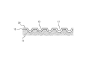
次に、図5乃至図8は、本発明に係る摺動部品100の他の実施の形態を示したものである。この摺動部品100の摺動面10の基本的な構成は、前記実施の形態と同様であるが、本実施の形態では、中間層20を形成する前にその摺動面10の表面にその中間層20の厚さよりも深い凹部12を多数形成したものである。
Next, FIGS. 5 to 8 show another embodiment of the sliding
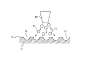
すなわち、図5に示すように先ず摺動面10の表面にショットピーニングやショットブラストと称される加工手段によってノズル50先端から圧縮空気によって粒径数μm〜数十μmのガラスビーズやアルミナビーズなどの硬質粒子51を高速噴射して摺動面10の表面に衝突させて多数の凹部12を均一に形成する。このとき、凹部12の深さは硬質粒子の大きさ(径)やその噴射速度を大きくすることで容易に調整できる。
That is, as shown in FIG. 5, first, glass beads or alumina beads having a particle diameter of several μm to several tens of μm by compressed air from the tip of the
次に、図6に示すようにその表面に前記実施の形態と同じ方法で中間層20を形成する。このとき、中間層20の厚さは凹部12の深さよりも薄くなるように調整する。すなわち、中間層20の厚さを凹部12の深さよりも薄くすれば、この中間層20によって凹部12が埋め立てられることがなく、その中心部分にほぼ相似形の凹部12をそのまま残すことができる。
Next, as shown in FIG. 6, the
その後、図7に示すように、前記実施の形態と同じく固体潤滑材粒子31である二硫化モリブデン粒子をエタノールなどのアルコールと混合し、懸濁状態にしたものをその中間層20の表面へ塗布する。このとき凹部12の内部に固体潤滑材粒子31を充填するようにしてその凹部12を固体潤滑材粒子31でほぼ完全に埋め立てるように塗布する。そして、全体に均一に塗布したならば、アルコールを揮発させてその中間層20の表面を固体潤滑材粒子31でほぼ平坦に被覆する。
Thereafter, as shown in FIG. 7, molybdenum disulfide particles, which are
最後に、図8に示すように転圧加工によってその摺動面10を平滑化する。具体的には、前記第1の実施の形態と同様に固体潤滑材粒子31で覆われた中間層20の表面をローラバニシング40で押し潰しながらその表面を平滑化する。
Finally, as shown in FIG. 8, the sliding
このとき、中間層20の平坦部分では、前記実施の形態と同様にその圧力によってその位置に配置された固体潤滑材粒子31がそのまま中間層20の表層に押し込まれるようにして埋没してその表面が平滑化されると共に、その表層に固体潤滑材粒子31からなる表面層30が形成される。一方、中間層20の凹部12では、その内部に充填された固体潤滑材粒子31が転圧加工によって押し固められて圧縮して密に充填された状態となり、これが固化して表面層30の一部を形成する。
At this time, in the flat portion of the
そして、このような構成をした摺動面10にあっては、前記実施の形態と同様にその表面層30と中間層20とが一体となるように強固に連結された状態となるため、その接合界面での剥離破壊リスクが抑制されて摺動面10の耐焼付性や耐摩耗性が大幅に向上する。さらに、凹部12には多くの固体潤滑材粒子31が充填された状態となっているため、この凹部12から摺動面10に十分な固体潤滑材31を供給することが可能となり、長期に亘って優れた潤滑性能を発揮できる。
And, in the sliding
100…摺動部品
10…摺動面
11…基材(母材)
12…凹部
20…中間層
30…表面層
31…固体潤滑材
40…転圧加工工具(ローラバニシング)
50…ノズル
51…硬質粒子
DESCRIPTION OF
DESCRIPTION OF
50 ...
Claims (3)
前記基材が鉄を主体とする材質からなると共に、前記中間層が銅、スズ、亜鉛のいずれかまたはそれら2種類以上の混合物からなり、
前記基材表面上に、前記中間層の厚さよりも深い凹部を複数有すると共に、前記各凹部内に前記固体潤滑材粒子が充填されていることを特徴とする摺動部品。 On the base material constituting the sliding surface, it has an intermediate layer made of a material different from that of the base material, and the surface layer of the intermediate layer has a surface layer embedded with solid lubricant particles ,
The base material is made of a material mainly composed of iron, and the intermediate layer is made of copper, tin, zinc, or a mixture of two or more of them,
A sliding part having a plurality of recesses deeper than the thickness of the intermediate layer on the surface of the base material, and the solid lubricant particles are filled in the recesses .
The sliding component according to claim 2 , wherein the solid lubricant particles are molybdenum disulfide.
Priority Applications (1)
| Application Number | Priority Date | Filing Date | Title |
|---|---|---|---|
| JP2014102279A JP6400330B2 (en) | 2014-05-16 | 2014-05-16 | Sliding parts and manufacturing method thereof |
Applications Claiming Priority (1)
| Application Number | Priority Date | Filing Date | Title |
|---|---|---|---|
| JP2014102279A JP6400330B2 (en) | 2014-05-16 | 2014-05-16 | Sliding parts and manufacturing method thereof |
Publications (3)
| Publication Number | Publication Date |
|---|---|
| JP2015217580A JP2015217580A (en) | 2015-12-07 |
| JP2015217580A5 JP2015217580A5 (en) | 2017-05-25 |
| JP6400330B2 true JP6400330B2 (en) | 2018-10-03 |
Family
ID=54777404
Family Applications (1)
| Application Number | Title | Priority Date | Filing Date |
|---|---|---|---|
| JP2014102279A Active JP6400330B2 (en) | 2014-05-16 | 2014-05-16 | Sliding parts and manufacturing method thereof |
Country Status (1)
| Country | Link |
|---|---|
| JP (1) | JP6400330B2 (en) |
Families Citing this family (2)
| Publication number | Priority date | Publication date | Assignee | Title |
|---|---|---|---|---|
| JP7138855B2 (en) * | 2018-05-15 | 2022-09-20 | 帝国イオン株式会社 | Wear-resistant coating, wear-resistant member, and method for producing wear-resistant coating |
| WO2019225624A1 (en) * | 2018-05-22 | 2019-11-28 | 帝国イオン株式会社 | Wear-resistant coating film, wear-resistant member, method for producing wear-resistant coating film, and sliding mechanism |
Family Cites Families (2)
| Publication number | Priority date | Publication date | Assignee | Title |
|---|---|---|---|---|
| JP4358801B2 (en) * | 2005-08-08 | 2009-11-04 | 大同メタル工業株式会社 | Slide bearing for internal combustion engine |
| JP6196800B2 (en) * | 2013-05-01 | 2017-09-13 | 株式会社栗本鐵工所 | Sliding member |
-
2014
- 2014-05-16 JP JP2014102279A patent/JP6400330B2/en active Active
Also Published As
| Publication number | Publication date |
|---|---|
| JP2015217580A (en) | 2015-12-07 |
Similar Documents
| Publication | Publication Date | Title |
|---|---|---|
| JP4688161B2 (en) | Sliding member and coating layer forming method thereof | |
| JP4890839B2 (en) | Multi-layer sliding member and method for forming coating layer of sliding member | |
| CN105829743B (en) | bearing element and method for manufacturing bearing element | |
| KR101660436B1 (en) | Welding tool used for double-acting type friction stir welding or double-acting type friction stir spot welding, and welding device using same | |
| JP5903391B2 (en) | Manufacturing method of sliding member | |
| EP2188540B1 (en) | Metal-backed plain bearing | |
| CN105247230A (en) | Sliding engine component | |
| WO2004063584A1 (en) | Sliding bearing | |
| JP2017534460A (en) | Laser cladding mechanical seal | |
| JP5252604B2 (en) | Synchronous ring assembly and method for forming a friction lining of a synchronous ring | |
| JP6400330B2 (en) | Sliding parts and manufacturing method thereof | |
| CN105579723B (en) | Sliding component and the manufacture method of sliding component | |
| JP2013204807A (en) | Sliding bearing | |
| Hua et al. | Friction properties and lubrication mechanism of self-lubricating composite solid lubricant on laser textured AISI 52100 surface in sliding contact | |
| JP5479658B1 (en) | piston ring | |
| TWI530344B (en) | Sliding member and method of manufacturing the same | |
| JP6342825B2 (en) | Bearing and fuel injection pump | |
| JP5551256B2 (en) | Sliding member manufacturing method and sliding member | |
| JP2015200339A (en) | Slide member | |
| JPH09202978A (en) | Wear resistant member having excellent wear resistance and its production | |
| JP2018119593A (en) | Slide member | |
| JP5898859B2 (en) | Resin bearing and manufacturing method thereof | |
| JP5249295B2 (en) | Lining method | |
| JP2007303622A (en) | Sliding member | |
| JP2015072050A (en) | Slide component and slide component manufacturing method |
Legal Events
| Date | Code | Title | Description |
|---|---|---|---|
| A521 | Written amendment |
Free format text: JAPANESE INTERMEDIATE CODE: A523 Effective date: 20170410 |
|
| A621 | Written request for application examination |
Free format text: JAPANESE INTERMEDIATE CODE: A621 Effective date: 20170410 |
|
| A977 | Report on retrieval |
Free format text: JAPANESE INTERMEDIATE CODE: A971007 Effective date: 20180117 |
|
| A131 | Notification of reasons for refusal |
Free format text: JAPANESE INTERMEDIATE CODE: A131 Effective date: 20180130 |
|
| A521 | Written amendment |
Free format text: JAPANESE INTERMEDIATE CODE: A523 Effective date: 20180329 |
|
| TRDD | Decision of grant or rejection written | ||
| A01 | Written decision to grant a patent or to grant a registration (utility model) |
Free format text: JAPANESE INTERMEDIATE CODE: A01 Effective date: 20180904 |
|
| A61 | First payment of annual fees (during grant procedure) |
Free format text: JAPANESE INTERMEDIATE CODE: A61 Effective date: 20180905 |
|
| R150 | Certificate of patent or registration of utility model |
Ref document number: 6400330 Country of ref document: JP Free format text: JAPANESE INTERMEDIATE CODE: R150 |