JP6388139B2 - Case and watch - Google Patents

Case and watch Download PDF

Info

Publication number
JP6388139B2
JP6388139B2 JP2016176320A JP2016176320A JP6388139B2 JP 6388139 B2 JP6388139 B2 JP 6388139B2 JP 2016176320 A JP2016176320 A JP 2016176320A JP 2016176320 A JP2016176320 A JP 2016176320A JP 6388139 B2 JP6388139 B2 JP 6388139B2
Authority
JP
Japan
Prior art keywords
case
main body
buffer member
body case
peripheral surface
Prior art date
Legal status (The legal status is an assumption and is not a legal conclusion. Google has not performed a legal analysis and makes no representation as to the accuracy of the status listed.)
Active
Application number
JP2016176320A
Other languages
Japanese (ja)
Other versions
JP2018040749A (en
Inventor
善弘 丸山
善弘 丸山
Current Assignee (The listed assignees may be inaccurate. Google has not performed a legal analysis and makes no representation or warranty as to the accuracy of the list.)
Casio Computer Co Ltd
Original Assignee
Casio Computer Co Ltd
Priority date (The priority date is an assumption and is not a legal conclusion. Google has not performed a legal analysis and makes no representation as to the accuracy of the date listed.)
Filing date
Publication date
Application filed by Casio Computer Co Ltd filed Critical Casio Computer Co Ltd
Priority to JP2016176320A priority Critical patent/JP6388139B2/en
Priority to CN201720733073.0U priority patent/CN206920829U/en
Publication of JP2018040749A publication Critical patent/JP2018040749A/en
Application granted granted Critical
Publication of JP6388139B2 publication Critical patent/JP6388139B2/en
Active legal-status Critical Current
Anticipated expiration legal-status Critical

Links

Images

Description

この発明は、腕時計、携帯電話機、携帯情報端末機などの電子機器に用いられるケースおよびそれを備えた時計に関する。   The present invention relates to a case used for an electronic device such as a wristwatch, a mobile phone, a portable information terminal, and a timepiece having the case.

例えば、腕時計の腕時計ケースにおいては、特許文献1に記載されているように、時計モジュールを収容する本体ケースと、この本体ケースの上部に時計ガラスを固定するための外装ケースと、を備えた構成のものが知られている。   For example, in a wristwatch case of a wristwatch, as described in Patent Document 1, a configuration including a main body case for accommodating a timepiece module and an outer case for fixing a timepiece glass to the upper portion of the main body case. Things are known.

特開2001−296375号公報JP 2001-296375 A

この種の腕時計ケースは、外装ケースが本体ケースの外周部に配置され、この外装ケースの上部に押え部が内周側に突出して設けられ、この突出した押え部が時計ガラスの縁部を上側から押え付けた状態で、外装ケースが本体ケースの外周部にねじ部材によって固定されるように構成されている。   In this type of watch case, the outer case is disposed on the outer periphery of the main body case, and the presser portion is provided on the outer case so as to protrude to the inner peripheral side. The outer case is configured to be fixed to the outer peripheral portion of the main body case with a screw member in a state where the outer case is pressed.

しかしながら、このような腕時計ケースでは、外装ケースが外部から衝撃を受けると、その衝撃が本体ケースおよび時計ガラスに直接伝わり、時計ガラスが割れたり、本体ケース内の時計モジュールが破損したりするため、耐衝撃性を確保することができないという問題がある。   However, in such a watch case, when the exterior case receives an impact from the outside, the impact is directly transmitted to the main body case and the watch glass, and the watch glass is broken or the watch module in the main body case is damaged. There is a problem that impact resistance cannot be ensured.

この発明が解決しようとする課題は、耐衝撃性に優れたケースおよびそれを備えた時計を提供することである。   The problem to be solved by the present invention is to provide a case having excellent impact resistance and a timepiece having the case.

この発明は、本体ケースと、この本体ケースの上部に固定される上部ケースとを備え、前記上部ケースは、前記本体ケースの上部にその内周側に位置した状態で固定された内側ケースと、前記本体ケースの上部にその外周側に位置した状態で配置された外側ケースと、前記内側ケースと前記外側ケースとの間に設けられ、弾性変形する第一の緩衝部材と、前記本体ケース上面と前記外側ケースの下面との間に設けられ、弾性変形する第二の緩衝部材と、を備え、前記内側ケースと前記本体ケースは前記第一の緩衝部材のみを介して接触し、前記外側ケースと前記本体ケースは前記第二の緩衝部材のみを介して接触する、ことを特徴とするケースである。 The present invention includes a main body case and an upper case fixed to the upper portion of the main body case, and the upper case is fixed to an upper portion of the main body case in a state of being positioned on an inner peripheral side thereof; an outer casing in which the disposed in a state of being positioned on the outer peripheral side at the top of the main body case is provided between the outer casing and the inner casing, the first slow衝部material elastically deformed, the main body case upper surface And a second shock-absorbing member that is elastically deformed, and the inner case and the main body case are in contact with each other only through the first shock-absorbing member. The main body case is in contact with only the second buffer member .

この発明によれば、外側ケースが外部から衝撃を受けた際に、その衝撃を内側ケースと外側ケースとの間の緩衝部材によって確実にかつ良好に緩衝することができるので、耐衝撃性に優れたものを提供することができる。   According to the present invention, when the outer case receives an impact from the outside, the shock can be reliably and satisfactorily buffered by the buffer member between the inner case and the outer case, so that the impact resistance is excellent. Can be provided.

この発明を腕時計に適用した一実施形態を示した拡大正面図である。1 is an enlarged front view showing an embodiment in which the present invention is applied to a wristwatch. 図1に示された腕時計のA−A矢視における要部を示した拡大断面図である。FIG. 2 is an enlarged cross-sectional view showing the main part of the watch shown in FIG. 図2に示された腕時計ケースの要部を更に拡大して示した断面図である。FIG. 3 is a cross-sectional view illustrating an enlarged main part of the watch case shown in FIG. 2. 図2に示された腕時計ケースのカシメ部を示し、(a)はカシメ部をカシメる前の状態を示した要部の拡大断面図、(b)はカシメ部をカシメた状態を示した要部の拡大断面図である。2 shows a crimped portion of the watch case shown in FIG. 2, (a) is an enlarged cross-sectional view of a main portion showing a state before the crimped portion is crimped, and (b) is a main portion showing a state where the crimped portion is crimped. It is an expanded sectional view of a part. 図3に示された緩衝部材を一部破断して示した要部の拡大図である。FIG. 4 is an enlarged view of a main part of the cushioning member shown in FIG. 図5に示された緩衝部材の変形例を一部破断して示した要部の拡大図である。FIG. 6 is an enlarged view of a main part of a modification of the buffer member shown in FIG.

以下、図1〜図5を参照して、この発明を腕時計に適用した一実施形態について説明する。
この腕時計は、図1および図2に示すように、腕時計ケース1を備えている。この腕時計ケース1の上部開口部には、時計ガラス2がガラスパッキン2aを介して取り付けられている。この腕時計ケース1の下部には、裏蓋3が蓋パッキン3aを介して取り付けられている。
Hereinafter, an embodiment in which this invention is applied to a wristwatch will be described with reference to FIGS.
This wristwatch includes a wristwatch case 1 as shown in FIGS. A watch glass 2 is attached to the upper opening of the watch case 1 via a glass packing 2a. A back cover 3 is attached to the lower part of the watch case 1 via a cover packing 3a.

この腕時計ケース1の12時側と6時側とには、図1に示すように、時計バンド(図示せず)が取り付けられるバンド取付部BTが設けられている。また、この腕時計ケース1の3時側には、竜頭などのスイッチ装置SW1が設けられており、この腕時計ケース1の2時側、4時側、8時側には、押釦スイッチSW2がそれぞれ設けられている。   As shown in FIG. 1, a band attaching portion BT to which a watch band (not shown) is attached is provided on the watch case 1 at 12 o'clock side and 6 o'clock side. Further, a switch device SW1 such as a crown is provided on the 3 o'clock side of the watch case 1, and a push button switch SW2 is provided on the 2 o'clock side, 4 o'clock side, and 8 o'clock side of the watch case 1 respectively. It has been.

さらに、この腕時計ケース1は、図2に示すように、その内部に時計モジュール4が配置されるように構成されている。この時計モジュール4は、図示ないが、指針の運針によって時刻を指示する時計ムーブメント、時刻や日付などの情報を電気光学的に表示する表示部、これらを電気的に駆動する回路部などの時計機能に必要な各種の部品を備えている。   Further, as shown in FIG. 2, the watch case 1 is configured such that a watch module 4 is disposed therein. Although not shown, the timepiece module 4 has a timepiece function such as a timepiece movement for indicating time by moving a pointer, a display portion for displaying information such as time and date electro-optically, and a circuit portion for electrically driving them. It has various parts necessary for

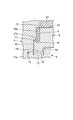
ところで、この腕時計ケース1は、図1および図2に示すように、時計モジュール4を収容する本体ケース5と、この本体ケース5の上部に固定されて時計ガラス2がガラスパッキン2aを介して装着する上部ケース6と、を備えている。本体ケース5は、ステンレス、チタンなどの金属で形成されている。   By the way, as shown in FIGS. 1 and 2, the watch case 1 includes a main body case 5 that houses the timepiece module 4, and a watch glass 2 that is fixed to the upper portion of the main body case 5 through a glass packing 2a. And an upper case 6 to be provided. The body case 5 is made of a metal such as stainless steel or titanium.

上部ケース6は、図2に示すように、本体ケース5の上部にその内周側に位置した状態で固定される内側ケース7と、本体ケース5の上部にその外周側に位置した状態で配置される外側ケース8と、内側ケース7と外側ケース8との間に設けられて、内側ケース7と外側ケース8とを非接触状態で配置させる緩衝部材9と、を備えている。なお、緩衝部材9は、防水部材としても機能している。   As shown in FIG. 2, the upper case 6 is disposed on the upper side of the main body case 5 while being fixed in a state of being positioned on the inner peripheral side, and on the upper side of the main body case 5 in a state of being positioned on the outer peripheral side. An outer case 8 and a buffer member 9 provided between the inner case 7 and the outer case 8 to dispose the inner case 7 and the outer case 8 in a non-contact state. The buffer member 9 also functions as a waterproof member.

内側ケース7は、図2に示すように、全体がほぼリング形状に形成されている。この内側ケース7は、その内径が本体ケース5の内径よりも小さく形成され、外径が本体ケース5の内径よりも大きく、かつ本体ケース5の外径よりも小さく形成されている。この場合、内側ケース7は、チタンなどの金属で形成されていることが望ましいが、本体ケース5と同様、ステンレスなどの金属で形成されていても良く、また必ずしも本体ケース5と同じ材料である必要はない。   As shown in FIG. 2, the inner case 7 is generally formed in a ring shape. The inner case 7 is formed so that the inner diameter is smaller than the inner diameter of the main body case 5, and the outer diameter is larger than the inner diameter of the main body case 5 and smaller than the outer diameter of the main body case 5. In this case, the inner case 7 is preferably formed of a metal such as titanium, but it may be formed of a metal such as stainless steel like the main body case 5, and is not necessarily the same material as the main body case 5. There is no need.

この内側ケース7は、その表面が蒸着などの表面処理によって所定の色、例えば黒色に着色されている。また、この内側ケース7の内周部には、図2に示すように、見切り部10とガラス装着部11とが設けられている。見切り部10は、内側ケース7の内周部の上部側から下部側に向けて次第に内径が小さくなるように傾斜して設けられている。   The surface of the inner case 7 is colored in a predetermined color, for example, black by a surface treatment such as vapor deposition. Further, as shown in FIG. 2, a parting portion 10 and a glass mounting portion 11 are provided on the inner peripheral portion of the inner case 7. The parting part 10 is provided to be inclined so that the inner diameter gradually decreases from the upper side to the lower side of the inner peripheral part of the inner case 7.

ガラス装着部11は、図2に示すように、見切り部10の上部における外周縁に起立して設けられた外周壁11aを備え、時計ガラス2の外周側の下面が内側ケース7の上面に配置された状態で、時計ガラス2の外周面がガラスパッキン2aを介して外周壁11aの内周面に圧接するように構成されている。   As shown in FIG. 2, the glass mounting part 11 includes an outer peripheral wall 11 a provided upright on the outer peripheral edge of the upper part of the parting part 10, and the lower surface on the outer peripheral side of the watch glass 2 is disposed on the upper surface of the inner case 7. In this state, the outer peripheral surface of the watch glass 2 is configured to be in pressure contact with the inner peripheral surface of the outer peripheral wall 11a through the glass packing 2a.

一方、外側ケース8は、図2に示すように、全体がほぼリング形状に形成されている。すなわち、この外側ケース8は、その内径が内側ケース7の外径と同じか、それよりも少し大きく形成され、外径が本体ケース5の外径よりも大きく形成されている。この場合、外側ケース8は、チタンなどの金属で形成されていることが望ましいが、内側ケース7と同様、ステンレスなどの金属で形成されていても良い。   On the other hand, as shown in FIG. 2, the entire outer case 8 is formed in a substantially ring shape. That is, the outer case 8 has an inner diameter that is the same as or slightly larger than the outer diameter of the inner case 7, and an outer diameter that is larger than the outer diameter of the main body case 5. In this case, the outer case 8 is preferably formed of a metal such as titanium, but may be formed of a metal such as stainless steel, like the inner case 7.

この場合にも、外側ケース8は、その表面が蒸着などの表面処理によって、内側ケース7と異なる色、例えば青色に着色されていることが望ましいが、内側ケース7と同じ色に着色されていても良い。また、この外側ケース8は、必ずしも金属で形成されている必要はなく、例えばセラミックス、石英ガラス、貴金属(金、銀、プラチナ)、人工宝石(人工サファイア、人工ルビー)などの材料で形成されていても良い。   Also in this case, the outer case 8 is preferably colored in a different color from the inner case 7, for example, blue by surface treatment such as vapor deposition, but is colored in the same color as the inner case 7. Also good. Further, the outer case 8 is not necessarily formed of a metal, and is formed of a material such as ceramics, quartz glass, noble metal (gold, silver, platinum), artificial gemstone (artificial sapphire, artificial ruby), or the like. May be.

ところで、上部ケース6は、図2に示すように、本体ケース5の内側上部に固定部12によって固定されるように構成されている。この固定部12は、内側ケース7を本体ケース5の内側上部に配置させて保持する保持部13と、この保持部13に設けられて本体ケース5の内周面にカシメ加工によって固定されるカシメ部14と、を備えている。   Incidentally, the upper case 6 is configured to be fixed to the inner upper portion of the main body case 5 by a fixing portion 12 as shown in FIG. The fixing portion 12 includes a holding portion 13 that holds the inner case 7 on the inner upper portion of the main body case 5, and a caulking that is provided on the holding portion 13 and fixed to the inner peripheral surface of the main body case 5 by caulking. Part 14.

保持部13は、図2に示すように、内側ケース7の下面におけるほぼ中間部に垂下して設けられた内周壁13aを備え、内側ケース7の外周部の下面が本体ケース5の内周側の上面に当接した状態で、内周壁13aの外周面が本体ケース5の内周面に接触する状態で配置されるように構成されている。これにより、保持部13は、内側ケース7を本体ケース5の内側上部に配置させて、内側ケース7を本体ケース5の上部に保持するように構成されている。   As shown in FIG. 2, the holding portion 13 includes an inner peripheral wall 13 a provided to hang from substantially the middle portion of the lower surface of the inner case 7, and the lower surface of the outer peripheral portion of the inner case 7 is the inner peripheral side of the main body case 5. The outer peripheral surface of the inner peripheral wall 13 a is arranged so as to be in contact with the inner peripheral surface of the main body case 5 while being in contact with the upper surface of the main body case 5. Thus, the holding unit 13 is configured to place the inner case 7 on the inner upper portion of the main body case 5 and hold the inner case 7 on the upper portion of the main body case 5.

カシメ部14は、図2および図4に示すように、内側ケース7の保持部13の内周壁13aにおける下端部の複数箇所に設けられた爪部である。このカシメ部14は、内側ケース7の保持部13が本体ケース5の内周側の上部に配置された状態で、カシメ加工によってカシメられた際に、本体ケース5の内周面に設けられた凹部5a内に食い込んで、内側ケース7を本体ケース5に固定するように構成されている。   As shown in FIGS. 2 and 4, the caulking portion 14 is a claw portion provided at a plurality of locations on the lower end portion of the inner peripheral wall 13 a of the holding portion 13 of the inner case 7. The caulking portion 14 is provided on the inner peripheral surface of the main body case 5 when the inner case 7 is caulked by the caulking process with the holding portion 13 of the inner case 7 being disposed on the upper portion on the inner peripheral side. The inner case 7 is fixed to the main body case 5 by biting into the recess 5a.

すなわち、このカシメ部14は、図4(a)に示すように、内側ケース7の保持部13が本体ケース5の内周側の上部に配置された状態で、カシメ加工される前のときに、本体ケース5の内周面に設けられた凹部5aの外部に位置した状態で、本体ケース5の凹部5aに対応して配置されるように構成されている。   That is, as shown in FIG. 4A, the caulking portion 14 is in a state before the caulking process with the holding portion 13 of the inner case 7 disposed at the upper part on the inner peripheral side of the main body case 5. The main body case 5 is arranged so as to correspond to the concave portion 5a of the main body case 5 in a state of being located outside the concave portion 5a provided on the inner peripheral surface of the main body case 5.

また、このカシメ部14は、図4(b)に示すように、本体ケース5の内周面に設けられた凹部5aに対応して配置された状態で、カシメ加工によってカシメられた際に、本体ケース5の内周面に設けられた凹部5a内に食い込むことにより、内側ケース7を本体ケース5に強固に固定するように構成されている。   In addition, as shown in FIG. 4 (b), the crimping portion 14 is disposed in correspondence with the recess 5a provided on the inner peripheral surface of the main body case 5, and when crimped by crimping, The inner case 7 is configured to be firmly fixed to the main body case 5 by biting into a recess 5 a provided on the inner peripheral surface of the main body case 5.

また、上部ケース6は、図2および図3に示すように、内側ケース7の外周面に設けられて、緩衝部材9を上方から押え付ける押え部15と、外側ケース8の内周面に設けられ、押え部15によって押え付けられた緩衝部材9が上方から押し当てられて本体ケース5の上部に向けて押し付けられる受け部16と、を備えている。   As shown in FIGS. 2 and 3, the upper case 6 is provided on the outer peripheral surface of the inner case 7 and is provided on the inner peripheral surface of the outer case 8 and the pressing portion 15 that presses the buffer member 9 from above. And a receiving portion 16 that is pressed against the upper portion of the main body case 5 by the shock-absorbing member 9 pressed by the pressing portion 15 from above.

押え部15は、図2および図3に示すように、内側ケース7の見切り部10の上部に対応する外周部に設けられた段差部である。すなわち、内側ケース7の見切り部10に対応する外周部のほぼ中間部には、緩衝部材9が配置される内側切欠き凹部15aが設けられている。このため、押え部15は、内側切欠き凹部15aの上端部に段差部として形成されている。   As shown in FIGS. 2 and 3, the presser portion 15 is a step portion provided on the outer peripheral portion corresponding to the upper portion of the parting portion 10 of the inner case 7. That is, an inner notch recess 15 a in which the buffer member 9 is disposed is provided at a substantially middle portion of the outer peripheral portion corresponding to the parting portion 10 of the inner case 7. For this reason, the presser portion 15 is formed as a stepped portion at the upper end portion of the inner notch recess 15a.

これにより、押え部15は、図2および図3に示すように、内側ケース7の保持部13が本体ケース5の内周側の上部に配置された際に、内側切欠き凹部15aに配置された緩衝部材9を上方から押え付けて外側ケース8の受け部16に押し付けることにより、外側ケース8を本体ケース5の上部に押え付けるように構成されている。   Thereby, as shown in FIG. 2 and FIG. 3, when the holding portion 13 of the inner case 7 is disposed at the upper portion on the inner peripheral side of the main body case 5, the presser portion 15 is disposed in the inner notch recess 15 a. The buffer member 9 is pressed from above and pressed against the receiving portion 16 of the outer case 8 so that the outer case 8 is pressed against the upper portion of the main body case 5.

一方、外側ケース8の受け部16は、図2および図3に示すように、外側ケース8の内周面の下部に設けられた段差突起部であり、内側ケース7の内側切欠き凹部15aの下側に位置した状態で、外側ケース8の内周部にその内周側に向けて突出して設けられている。すなわち、この受け部16は、内側ケース7の内側切欠き凹部15aに配置された緩衝部材9の下側に位置し、緩衝部材9の下面が配置されるように構成されている。   On the other hand, as shown in FIGS. 2 and 3, the receiving portion 16 of the outer case 8 is a step protrusion provided at the lower portion of the inner peripheral surface of the outer case 8, and the inner notch recess 15a of the inner case 7 is formed. In a state of being located on the lower side, the outer case 8 is provided so as to protrude toward the inner peripheral side thereof. That is, the receiving portion 16 is configured to be positioned below the buffer member 9 disposed in the inner notch recess 15a of the inner case 7 and the lower surface of the buffer member 9 is disposed.

これにより、受け部16は、図2および図3に示すように、内側ケース7の保持部13が本体ケース5の内周側の上部に配置される際に、受け部16の上面に配置された緩衝部材9が内側ケース7の押え部15によって押え付けられ、この押え付けられた緩衝部材9によって本体ケース5の上部に向けて押え付けられるように構成されている。   Thereby, as shown in FIGS. 2 and 3, the receiving portion 16 is disposed on the upper surface of the receiving portion 16 when the holding portion 13 of the inner case 7 is disposed at the upper portion on the inner peripheral side of the main body case 5. The buffer member 9 is pressed by the pressing portion 15 of the inner case 7 and is pressed toward the upper portion of the main body case 5 by the buffer member 9 pressed.

この場合、外側ケース8の下端部は、図2および図3に示すように、本体ケース5の上端部に設けられた溝部17内に配置された防水部材18を押し付ける支持突起部19が外側ケース8の下側に突出して設けられている。本体ケース5の溝部17は、本体ケース5の上端面における中間部にリング状に設けられた凹溝である。この溝部17の外周側に位置する本体ケース5の上部には、支持突起部19の外周を隠すための目隠し部5bが上方に突出して設けられている。   In this case, as shown in FIGS. 2 and 3, the lower end portion of the outer case 8 has a support protrusion 19 that presses the waterproof member 18 disposed in the groove portion 17 provided in the upper end portion of the main body case 5. 8 is provided to protrude downward. The groove portion 17 of the main body case 5 is a concave groove provided in a ring shape at an intermediate portion of the upper end surface of the main body case 5. On the upper portion of the main body case 5 located on the outer peripheral side of the groove portion 17, a blindfold portion 5 b for concealing the outer periphery of the support projection portion 19 is provided so as to protrude upward.

支持突起部19は、図2および図3に示すように、外側ケース8の下端面における受け部16の下側に突出した状態で、リング状に形成されている。この支持突起部19は、その径方向の長さが本体ケース5の溝部17の径方向の長さよりも少し短く形成されている。また、この支持突起部19は、その下端面が内側ケース7の下面と同じ高さで、かつ下側に突出する長さが、本体ケース5の上部に設けられた目隠し部5bの高さよりも少し長く形成されている。   As shown in FIGS. 2 and 3, the support protrusion 19 is formed in a ring shape so as to protrude below the receiving portion 16 on the lower end surface of the outer case 8. The support protrusion 19 is formed so that its radial length is slightly shorter than the radial length of the groove portion 17 of the main body case 5. In addition, the support protrusion 19 has a lower end surface that is the same height as the lower surface of the inner case 7 and has a length that protrudes downward from the height of the blind portion 5 b provided on the upper portion of the main body case 5. It is formed a little longer.

防水部材18は、図2および図3に示すように、ゴムなどの弾力を有する合成樹脂によってリング状に形成され、本体ケース5の溝部17内に嵌め込まれるように構成されている。すなわち、この防水部材18は、リング状の溝部17内の形状とほぼ同じ形状でほぼ同じ大きさに形成されている。   As shown in FIGS. 2 and 3, the waterproof member 18 is formed in a ring shape from a synthetic resin having elasticity such as rubber, and is configured to be fitted into the groove portion 17 of the main body case 5. That is, the waterproof member 18 is formed in substantially the same size and shape as the shape in the ring-shaped groove portion 17.

これにより、支持突起部19は、図2および図3に示すように、外側ケース8が本体ケース5の上部に配置される際に、支持突起部19の下端部が本体ケース5の溝部17内の防水部材18に対応し、支持突起部19の外周部が本体ケース5の溝部17の外周に位置する目隠し部5bの内周面に非接触状態で対応し、この状態で外側ケース8を本体ケース5の上部に支持するように構成されている。   Thereby, as shown in FIGS. 2 and 3, when the outer case 8 is disposed on the upper portion of the main body case 5, the lower end portion of the support protrusion 19 is located in the groove portion 17 of the main body case 5. The outer peripheral portion of the support projection 19 corresponds to the inner peripheral surface of the blindfold portion 5b located on the outer periphery of the groove portion 17 of the main body case 5 in a non-contact state. The upper portion of the case 5 is configured to be supported.

このため、外側ケース8は、図2に示すように、内側ケース7の押え部15によって押え付けられた緩衝部材9が外側ケース8の受け部16を押し付けた際に、支持突起部19の下端部が防水部材18に押し当てられることにより、外側ケース8が内側ケース7および本体ケース5に接触せず、本体ケース5に対してフローティング状態で配置されるように構成されている。   Therefore, as shown in FIG. 2, the outer case 8 has a lower end of the support protrusion 19 when the buffer member 9 pressed by the pressing portion 15 of the inner case 7 presses the receiving portion 16 of the outer case 8. When the portion is pressed against the waterproof member 18, the outer case 8 is configured not to contact the inner case 7 and the main body case 5 but to be arranged in a floating state with respect to the main body case 5.

ところで、緩衝部材9は、図5に示すように、断面がほぼ長方形のリング状に形成されている。すなわち、この緩衝部材9は、その内径が内側ケース7の内側切欠き凹部15aの外径と同じ大きさで、外径が外側ケース8の受け部16の上側に位置する内周面の内径と同じ大きさに形成されている。この緩衝部材9は、ポリアミドなどの弾力性を有する合成樹脂によって形成されている。   Incidentally, as shown in FIG. 5, the buffer member 9 is formed in a ring shape having a substantially rectangular cross section. That is, the buffer member 9 has the same inner diameter as the outer diameter of the inner notch recess 15 a of the inner case 7, and the outer diameter is equal to the inner diameter of the inner peripheral surface located above the receiving portion 16 of the outer case 8. It is formed in the same size. This buffer member 9 is formed of a synthetic resin having elasticity such as polyamide.

これにより、緩衝部材9は、図2および図3に示すように、内側ケース7の内側切欠き凹部15aの外周面と外側ケース8の受け部16の上側に位置する内周面との間に配置された状態で、内側ケース7の押え部15と外側ケース8の受け部16との間に上下方向に挟み付けられた際に、弾力的に変形するように構成されている。   Accordingly, the buffer member 9 is formed between the outer peripheral surface of the inner notch recess 15a of the inner case 7 and the inner peripheral surface of the outer case 8 located above the receiving portion 16 as shown in FIGS. In the state of being arranged, it is configured to be elastically deformed when sandwiched in the vertical direction between the pressing portion 15 of the inner case 7 and the receiving portion 16 of the outer case 8.

この場合、緩衝部材9の内周面の上部と外周面の下部とには、図5に示すように、それぞれ面取り部9aが設けられている。この緩衝部材9の内周面の上部に設けられた面取り部9aは、内側ケース7の内側切欠き凹部15aに緩衝部材9を装着し易くするように構成されている。また、この緩衝部材9の外周面の下部に設けられた面取り部9aは、外側ケース8の受け部16の上側に位置する内周面に緩衝部材9を装着し易くするように構成されている。   In this case, as shown in FIG. 5, chamfered portions 9a are respectively provided at the upper part of the inner peripheral surface of the buffer member 9 and the lower part of the outer peripheral surface. A chamfered portion 9 a provided at the upper portion of the inner peripheral surface of the buffer member 9 is configured to facilitate mounting of the buffer member 9 in the inner notch recess 15 a of the inner case 7. Further, the chamfered portion 9 a provided at the lower portion of the outer peripheral surface of the buffer member 9 is configured to facilitate mounting of the buffer member 9 on the inner peripheral surface located above the receiving portion 16 of the outer case 8. .

ところで、内側ケース7の外周面には、図2および図3に示すように、外側ケース8の受け部16が径方向に食い込む食込み凹部20が、押え部15の内側切欠き凹部15aの下端部から内側ケース7の保持部13の下面に亘って設けられている。この内側ケース7の食込み凹部20と外側ケース8の受け部16の上面との間には、緩衝部材9が圧縮された際に、緩衝部材9が食い込むための逃げ部21が設けられている。   By the way, as shown in FIG. 2 and FIG. 3, a biting recess 20 into which the receiving portion 16 of the outer case 8 bites in the radial direction is formed on the outer peripheral surface of the inner case 7. To the lower surface of the holding portion 13 of the inner case 7. Between the biting recess 20 of the inner case 7 and the upper surface of the receiving portion 16 of the outer case 8, there is provided an escape portion 21 for biting the buffer member 9 when the buffer member 9 is compressed.

この逃げ部21は、図2および図3に示すように、外側ケース8の受け部16の上面とこれに対向する内側ケース7の食込み凹部20の下面との間の隙間であり、内側ケース7の内側切欠き凹部15aの下端部に逃し傾斜部21aが設けられた構成になっている。この逃し傾斜部21aは、緩衝部材9が内側ケース7の押え部15と外側ケース8の受け部16との間で圧縮されて変形する際に、その変形する緩衝部材9を逃げ部21に逃し易くするように構成されている。   As shown in FIGS. 2 and 3, the escape portion 21 is a gap between the upper surface of the receiving portion 16 of the outer case 8 and the lower surface of the biting recess 20 of the inner case 7 opposite to the receiving portion 16. This is a configuration in which a relief inclined portion 21a is provided at the lower end of the inner notch recess 15a. The relief inclined portion 21 a allows the buffer member 9 to be deformed to the escape portion 21 when the buffer member 9 is compressed and deformed between the holding portion 15 of the inner case 7 and the receiving portion 16 of the outer case 8. It is configured to facilitate.

これにより、緩衝部材9は、図2および図3に示すように、内側ケース7の内側切欠き凹部15aの外周面と外側ケース8の受け部16の上側に位置する内周面との間に配置された状態で、内側ケース7の押え部15と外側ケース8の受け部16との間で挟み付けられて圧縮変形する際に、緩衝部材9の下部が受け部16の上面と食込み凹部20の下面との間の逃げ部21に食い込むように構成されている。このため、この緩衝部材9は、内側ケース7の外周面と外側ケース8の内周面との間の防水を図るように構成されている。   Accordingly, the buffer member 9 is formed between the outer peripheral surface of the inner notch recess 15a of the inner case 7 and the inner peripheral surface of the outer case 8 located above the receiving portion 16 as shown in FIGS. In a state where the cushioning member 9 is sandwiched between the holding part 15 of the inner case 7 and the receiving part 16 of the outer case 8 and is compressed and deformed, the lower part of the cushioning member 9 is in contact with the upper surface of the receiving part 16 and the biting recess 20. It is comprised so that it may bite into the escape part 21 between the lower surfaces of. For this reason, the buffer member 9 is configured to be waterproof between the outer peripheral surface of the inner case 7 and the inner peripheral surface of the outer case 8.

また、外側ケース8には、図2に示すように、装飾部材23が装着する装着部22が設けられている。この装着部22は、外側ケース8の上部に設けられたリング状の切欠き溝部であり、緩衝部材9よりも上側に位置し、外側ケース8の外周部を除いて内周側および上側に開放された状態で設けられている。これにより、この装着部22は、その内部に上方から装飾部材23が装着するように構成されている。   Further, as shown in FIG. 2, the outer case 8 is provided with a mounting portion 22 to which the decorative member 23 is mounted. The mounting portion 22 is a ring-shaped cutout groove provided in the upper part of the outer case 8, is located above the buffer member 9, and is open to the inner peripheral side and the upper side except for the outer peripheral portion of the outer case 8. It is provided in the state that was done. Thereby, this mounting part 22 is comprised so that the decoration member 23 may be mounted on the inside from above.

装飾部材23は、図2に示すように、上部ケース6を装飾するためのものであり、装着部22とほぼ同じ大きさのリング状に形成され、外側ケース8の装着部22内に接着剤(図示せず)によって接着されて固定されるように構成されている。この装飾部材23は、外側ケース8と同様、ステンレス、チタン、セラミックス、石英ガラス、貴金属(金、銀、プラチナ)、人工宝石(人工サファイア、人工ルビー)などの材料で形成されていても良いが、貝、木、石などの天然物、または合成樹脂などの装飾性を有する材料で形成されていても良い。   As shown in FIG. 2, the decoration member 23 is for decorating the upper case 6, is formed in a ring shape having substantially the same size as the mounting portion 22, and has an adhesive in the mounting portion 22 of the outer case 8. (Not shown) is configured to be bonded and fixed. Like the outer case 8, the decorative member 23 may be formed of a material such as stainless steel, titanium, ceramics, quartz glass, noble metal (gold, silver, platinum), or artificial gemstone (artificial sapphire, artificial ruby). Further, it may be formed of a natural material such as shellfish, wood or stone, or a decorative material such as a synthetic resin.

次に、この腕時計ケース1の作用について説明する。
この腕時計ケース1を組み立てる場合には、まず、上部ケース6の内側ケース7の外周に外側ケース8を配置して上部ケース6を組み立て、この上部ケース6を本体ケース5の上部に取り付ける。
Next, the operation of the watch case 1 will be described.
When assembling the watch case 1, first, the outer case 8 is arranged on the outer periphery of the inner case 7 of the upper case 6 to assemble the upper case 6, and the upper case 6 is attached to the upper part of the main body case 5.

この場合には、予め、内側ケース7の外周部における押え部15の下側に位置する内側切欠き凹部15aに緩衝部材9を装着させる。このときには、緩衝部材9の内周面の上部に面取り部9aが設けられているので、この面取り部9aによって緩衝部材9を内側ケース7の内側切欠き凹部15aに容易に装着させることができる。また、このときには、外装ケース8の装着部22に装飾部材23を接着剤によって接着させて装着させる。   In this case, the shock-absorbing member 9 is attached in advance to the inner notch recess 15a located on the lower side of the pressing portion 15 in the outer peripheral portion of the inner case 7. At this time, since the chamfered portion 9a is provided on the upper portion of the inner peripheral surface of the buffer member 9, the buffer member 9 can be easily mounted on the inner notch recess 15a of the inner case 7 by the chamfered portion 9a. At this time, the decorative member 23 is attached to the mounting portion 22 of the outer case 8 with an adhesive.

この状態で、外側ケース8を内側ケース7の外周にその下側から嵌め込んで、内側ケース7と外側ケース8とを組み合わせる。このときには、内側ケース7の押え部15における内側切欠き凹部15aに装着された緩衝部材9の外周面に、外側ケース8の受け部16の上側に位置する内周面を配置させる。この場合には、緩衝部材9の外周面の下部に設けられた面取り部9aによって、外側ケース8を内側ケース7の内側切欠き凹部15aに装着された緩衝部材9に容易に装着させることができる。   In this state, the outer case 8 is fitted into the outer periphery of the inner case 7 from below, and the inner case 7 and the outer case 8 are combined. At this time, the inner peripheral surface located on the upper side of the receiving portion 16 of the outer case 8 is disposed on the outer peripheral surface of the buffer member 9 mounted in the inner notch recess 15 a in the presser portion 15 of the inner case 7. In this case, the outer case 8 can be easily mounted on the buffer member 9 mounted in the inner notch recess 15 a of the inner case 7 by the chamfered portion 9 a provided at the lower portion of the outer peripheral surface of the buffer member 9. .

これにより、緩衝部材9は、内側ケース7の内側切欠き凹部15aの外周面と外側ケース8の受け部16の上側に位置する内周面との間に挟まれると共に、内側ケース7の押え部15の下面と外側ケース8の受け部16の上面との間に挟まれる。この状態では、外側ケース8の受け部16が内側ケース7の内側切欠き凹部15aの下側に位置する食込み凹部20に食込み、外側ケース8の受け部16の上面とこれに対応する食込み凹部20の下面との間に逃げ部21が設けられる。   Thus, the buffer member 9 is sandwiched between the outer peripheral surface of the inner notch recess 15a of the inner case 7 and the inner peripheral surface located above the receiving portion 16 of the outer case 8, and the holding portion of the inner case 7 15 and the upper surface of the receiving portion 16 of the outer case 8. In this state, the receiving portion 16 of the outer case 8 bites into the biting recess 20 located below the inner notch recess 15a of the inner case 7, and the upper surface of the receiving portion 16 of the outer case 8 and the corresponding biting recess 20 An escape portion 21 is provided between the lower surface of the first and second surfaces.

また、この状態では、内側ケース7の下部に位置する保持部13の外周側の上面と外側ケース8の下端部から突出した支持突起部19の下端面とが同じ高さで配置される。さらに、この状態では、内側ケース7のガラス装着部11における外周壁11aの外周面に、外側ケース8の装着部22に装着された装飾部材23の内周面が対応し、内側ケース7のガラス装着部11における外周壁11aの上部と装飾部材23の上部とがほぼ同じ高さで配置される。   Further, in this state, the upper surface on the outer peripheral side of the holding portion 13 located at the lower portion of the inner case 7 and the lower end surface of the support protrusion 19 protruding from the lower end portion of the outer case 8 are arranged at the same height. Further, in this state, the inner peripheral surface of the decorative member 23 mounted on the mounting portion 22 of the outer case 8 corresponds to the outer peripheral surface of the outer peripheral wall 11 a of the glass mounting portion 11 of the inner case 7. The upper part of the outer peripheral wall 11a and the upper part of the decorative member 23 in the mounting part 11 are arranged at substantially the same height.

これにより、内側ケース7と外側ケース8とが組み合われて、上部ケース6が構成される。そして、この上部ケース6を本体ケース5の上部に取り付ける。このときには、予め、本体ケース5の上部に設けられた溝部17内に防水部材18を配置する。この状態で、内側ケース7の保持部13を本体ケース5の内側上部に対応させると共に、外側ケース8の下端部に位置する支持突起部19を本体ケース5の溝部17内の防水部材18に対応させる。   Thereby, the inner case 7 and the outer case 8 are combined to form the upper case 6. Then, the upper case 6 is attached to the upper part of the main body case 5. At this time, the waterproof member 18 is previously disposed in the groove portion 17 provided in the upper portion of the main body case 5. In this state, the holding portion 13 of the inner case 7 is made to correspond to the inner upper portion of the main body case 5, and the support protrusion 19 located at the lower end portion of the outer case 8 corresponds to the waterproof member 18 in the groove portion 17 of the main body case 5. Let

そして、内側ケース7の保持部13を本体ケース5の内側上部に上方から嵌め込んで、保持部13の下面を本体ケース5の内周側の上面に当接させて、保持部13の内周壁13aの外周面を本体ケース5の内周面に対応させると共に、カシメ部14を本体ケース5の内面に設けられた凹部5aに対応させる。これにより、内側ケース7が本体ケース5の内側上部に保持される。   Then, the holding part 13 of the inner case 7 is fitted into the inner upper part of the main body case 5 from above, the lower surface of the holding part 13 is brought into contact with the upper surface on the inner peripheral side of the main body case 5, and the inner peripheral wall of the holding part 13 The outer peripheral surface of 13 a is made to correspond to the inner peripheral surface of the main body case 5, and the caulking portion 14 is made to correspond to the concave portion 5 a provided on the inner surface of the main body case 5. As a result, the inner case 7 is held on the inner upper portion of the main body case 5.

このときには、内側ケース7の押え部15の下面が緩衝部材9を押え付け、この緩衝部材9が外側ケース8の受け部16の上面を押え付ける。このため、外側ケース8が本体ケース5の上部に押し付けられることにより、この外側ケース8の支持突起部19が本体ケース5の溝部17内に配置された防水部材18を押圧させた状態で、外側ケース8の外周側の下面が本体ケース5の上部の目隠し部5bの上方に配置される。   At this time, the lower surface of the pressing portion 15 of the inner case 7 presses the buffer member 9, and the buffer member 9 presses the upper surface of the receiving portion 16 of the outer case 8. For this reason, when the outer case 8 is pressed against the upper part of the main body case 5, the support protrusion 19 of the outer case 8 presses the waterproof member 18 disposed in the groove 17 of the main body case 5, The lower surface on the outer peripheral side of the case 8 is arranged above the blindfold 5 b at the top of the main body case 5.

このため、外側ケース8は、内側ケース7および本体ケース5に非接触状態で、かつ本体ケース5に対してフローティング状態で配置される。この状態で、上部ケース6を本体ケース5の上部に固定する際には、内側ケース7の保持部13の下端部に設けられたカシメ部14をカシメして本体ケース5の凹部5aに食い込ませる。これにより、内側ケース7が本体ケース5に強固に固定され、これに伴って外側ケース8が本体ケース5に対してフローティング状態で固定される。   For this reason, the outer case 8 is arranged in a non-contact state with the inner case 7 and the main body case 5 and in a floating state with respect to the main body case 5. In this state, when the upper case 6 is fixed to the upper portion of the main body case 5, the caulking portion 14 provided at the lower end portion of the holding portion 13 of the inner case 7 is caulked to bite into the concave portion 5 a of the main body case 5. . Thereby, the inner case 7 is firmly fixed to the main body case 5, and accordingly, the outer case 8 is fixed to the main body case 5 in a floating state.

この状態では、緩衝部材9が内側ケース7の内側切欠き凹部15aの外周面と外側ケース8の受け部16の上側に位置する内周面との間に配置された状態で、内側ケース7の押え部15と外側ケース8の受け部16との間で挟み付けられて圧縮変形する。このため、この緩衝部材9によって内側ケース7の外周面と外側ケース8の内周面との間の防水が図れる。   In this state, the buffer member 9 is disposed between the outer peripheral surface of the inner notch recess 15 a of the inner case 7 and the inner peripheral surface located above the receiving portion 16 of the outer case 8. It is sandwiched between the holding part 15 and the receiving part 16 of the outer case 8 and is compressed and deformed. For this reason, waterproofing between the outer peripheral surface of the inner case 7 and the inner peripheral surface of the outer case 8 can be achieved by the buffer member 9.

このときには、緩衝部材9の下部が受け部16の上面と食込み凹部20の下面との間の逃げ部21に食い込む。この場合、逃げ部21は、内側ケース7の内側切欠き凹部15aの下端部に逃し傾斜部21aが設けられているので、この逃し傾斜部21aによって緩衝部材9が圧縮変形する際に、その変形する緩衝部材9を逃げ部21に容易に逃すことができる。これにより、腕時計ケース1が組み立てられる。   At this time, the lower portion of the buffer member 9 bites into the escape portion 21 between the upper surface of the receiving portion 16 and the lower surface of the biting recess 20. In this case, the escape portion 21 is provided with a relief inclined portion 21a at the lower end portion of the inner notch recess 15a of the inner case 7, so that when the buffer member 9 is compressed and deformed by the relief inclined portion 21a, the relief portion 21a is deformed. The buffer member 9 to be released can be easily escaped to the escape portion 21. Thereby, the wristwatch case 1 is assembled.

このように組み立てられた腕時計ケース1は、上部ケース6の内側ケース7におけるガラス装着部11に、時計ガラス2がガラスパッキン2aを介して装着される。また、この腕時計ケース1では、本体ケース5の内部に時計モジュール4が配置され、この本体ケース5の下部に裏蓋3が蓋パッキン3aを介して取り付けられる。これにより、腕時計が組み立てられる。   In the watch case 1 assembled in this way, the watch glass 2 is mounted on the glass mounting portion 11 of the inner case 7 of the upper case 6 via the glass packing 2a. In the wristwatch case 1, the timepiece module 4 is disposed inside the main body case 5, and the back cover 3 is attached to the lower portion of the main body case 5 via the lid packing 3 a. Thereby, the wristwatch is assembled.

このように組み立てられた腕時計では、腕時計ケース1の外側ケース8が外部から衝撃を受けた際に、その衝撃を内側ケース7と外側ケース8との間の緩衝部材9によって確実にかつ良好に緩衝することができるので、耐衝撃性の高いものを得ることができる。すなわち、内側ケース7と外側ケース8とは、緩衝部材9によって非接触状態で配置されることにより、外側ケース8が外部から衝撃を受けて緩衝部材9が衝撃を緩衝する際に、外側ケース8を衝撃に応じて変位させることができる。   In the wristwatch assembled in this way, when the outer case 8 of the watch case 1 receives an impact from the outside, the impact is reliably and satisfactorily buffered by the buffer member 9 between the inner case 7 and the outer case 8. Therefore, a high impact resistance can be obtained. That is, the inner case 7 and the outer case 8 are arranged in a non-contact state by the buffer member 9, so that when the outer case 8 receives an impact from the outside and the buffer member 9 buffers the impact, the outer case 8. Can be displaced in response to an impact.

これにより、この腕時計では、外側ケース8が横方向(径方向)から衝撃を受けても、その衝撃を緩衝部材9によって確実にかつ良好に緩衝することができることができるので、外側ケース8が外部から受けた衝撃が内側ケース7に伝わることがない。このため、内側ケース7に装着された時計ガラス2が衝撃によって割れることがなく、時計ガラス2を良好に保護することができると共に、外側ケース8の衝撃が本体ケース5に伝わることがないので、本体ケース5内の時計モジュール4が衝撃によって破損することがない。   Thereby, even if the outer case 8 receives an impact from the lateral direction (radial direction) in this wristwatch, the shock can be reliably and satisfactorily buffered by the buffer member 9, so that the outer case 8 is externally attached. The impact received from is not transmitted to the inner case 7. For this reason, the watch glass 2 attached to the inner case 7 is not broken by an impact, the watch glass 2 can be well protected, and the impact of the outer case 8 is not transmitted to the main body case 5. The timepiece module 4 in the main body case 5 is not damaged by an impact.

また、この腕時計では、外側ケース8が本体ケース5の上部に設けられた防水部材18に押し当てられることにより、本体ケース5に対して外側ケース8がフローティング状態で配置されている。このため、外側ケース8が上下方向(厚み方向)から衝撃を受けても、その衝撃が本体ケース5に伝わることがないので、本体ケース5内に配置された時計モジュール4が衝撃によって破損することがない。   Further, in this wristwatch, the outer case 8 is placed in a floating state with respect to the main body case 5 by pressing the outer case 8 against the waterproof member 18 provided on the upper portion of the main body case 5. For this reason, even if the outer case 8 receives an impact from the vertical direction (thickness direction), the impact is not transmitted to the main body case 5, so that the timepiece module 4 disposed in the main body case 5 is damaged by the impact. There is no.

このように、この腕時計ケース1によれば、本体ケース5の上部に固定される上部ケース6が、本体ケース5の上部にその内周側に位置した状態で固定される内側ケース7と、本体ケース5の上部にその外周側に位置した状態で配置される外側ケース8と、内側ケース7と外側ケース8との間に設けられて、内側ケース7と外側ケース8とを非接触状態で配置する緩衝部材9と、を備えていることにより、耐衝撃性に優れたものを提供することができる。   Thus, according to the wristwatch case 1, the upper case 6 fixed to the upper portion of the main body case 5 is fixed to the upper portion of the main body case 5 in a state of being positioned on the inner peripheral side thereof, The outer case 8 is disposed between the inner case 7 and the outer case 8 in a state of being positioned on the outer peripheral side of the upper portion of the case 5, and the inner case 7 and the outer case 8 are disposed in a non-contact state. By providing the cushioning member 9 to be provided, it is possible to provide a material having excellent impact resistance.

すなわち、この腕時計ケース1では、外側ケース8が外部から衝撃を受けた際に、その衝撃を内側ケース7と外側ケース8との間の緩衝部材9によって確実にかつ良好に緩衝することができる。この場合、内側ケース7と外側ケース8とは、緩衝部材9によって非接触状態で配置されているので、外側ケース8が外部から受けた衝撃を緩衝部材9が緩衝する際に、外側ケース8を衝撃に応じて変位させることができる。このため、緩衝部材9によって衝撃を確実にかつ良好に緩衝することができるので、耐衝撃性に優れたものを提供することができる。   That is, in the wristwatch case 1, when the outer case 8 receives an impact from the outside, the impact can be reliably and satisfactorily buffered by the buffer member 9 between the inner case 7 and the outer case 8. In this case, since the inner case 7 and the outer case 8 are arranged in a non-contact state by the buffer member 9, when the buffer member 9 buffers the impact received by the outer case 8 from the outside, It can be displaced according to the impact. For this reason, since the shock can be reliably and satisfactorily buffered by the buffer member 9, it is possible to provide a material having excellent impact resistance.

また、この腕時計ケース1では、内側ケース7が固定部12によって本体ケース5の上部に固定されていることにより、内側ケース7に外側ケース8を緩衝部材9によって確実に取り付けることができ、これにより外側ケース8を本体ケース5に対して良好に取り付けることができると共に、内側ケース7に装着された時計ガラス2を本体ケース5に対して確実に固定することができる。   In the wristwatch case 1, the inner case 7 is fixed to the upper part of the main body case 5 by the fixing portion 12, so that the outer case 8 can be securely attached to the inner case 7 by the buffer member 9. The outer case 8 can be satisfactorily attached to the main body case 5, and the watch glass 2 mounted on the inner case 7 can be securely fixed to the main body case 5.

すなわち、固定部12は、内側ケース7を本体ケース5の内側上部に配置させて保持する保持部13と、この保持部13に設けられて本体ケース5の内周面に設けられた凹部5aにカシメ加工によって固定されるカシメ部14と、を備えていることにより、保持部13によって内側ケース7を本体ケース5の上部に確実に保持することができると共に、カシメ部14によって内側ケース7を本体ケース5の上部に強固に固定することができる。   That is, the fixing portion 12 is provided in a holding portion 13 that holds the inner case 7 disposed on the inner upper portion of the main body case 5, and a concave portion 5 a that is provided in the holding portion 13 and provided on the inner peripheral surface of the main body case 5. And the caulking part 14 fixed by caulking, so that the inner case 7 can be securely held on the upper part of the main body case 5 by the holding part 13 and the inner case 7 is secured to the main body by the caulking part 14. It can be firmly fixed to the upper part of the case 5.

この場合、保持部13は、内側ケース7の下面におけるほぼ中間部に垂下して設けられた内周壁13aを備え、内側ケース7の外周部の下面が本体ケース5の内周側の上面に当接した状態で、内周壁13aの外周面が本体ケース5の内周面に接触する状態で配置される構成であるから、保持部13によって内側ケース7を本体ケース5の内側上部に配置させた状態で、内側ケース7を本体ケース5の上部に確実に保持させることができる。   In this case, the holding portion 13 includes an inner peripheral wall 13 a provided to hang substantially at the middle portion on the lower surface of the inner case 7, and the lower surface of the outer peripheral portion of the inner case 7 contacts the upper surface on the inner peripheral side of the main body case 5. Since the outer peripheral surface of the inner peripheral wall 13a is disposed in contact with the inner peripheral surface of the main body case 5, the inner case 7 is disposed on the inner upper portion of the main body case 5 by the holding portion 13. In this state, the inner case 7 can be securely held on the upper part of the main body case 5.

また、カシメ部14は、内側ケース7の保持部13の内周壁13aにおける下端部の複数箇所に設けられた爪部であり、内側ケース7の保持部13が本体ケース5の内周側の上部に配置された状態で、カシメ加工によって本体ケース5の内周面に設けられた凹部5a内に食い込む構成であるから、内側ケース7を本体ケース5に確実にかつ強固に固定することができる。   Further, the caulking portion 14 is a claw portion provided at a plurality of locations on the lower end portion of the inner peripheral wall 13 a of the holding portion 13 of the inner case 7, and the holding portion 13 of the inner case 7 is an upper portion on the inner peripheral side of the main body case 5. The inner case 7 can be securely and firmly fixed to the main body case 5 because the inner case 7 is bitten into the recess 5 a provided on the inner peripheral surface of the main body case 5 by caulking.

また、この腕時計ケース1では、上部ケース6が、内側ケース7の外周面に設けられて緩衝部材9を上方から押え付ける押え部15と、外側ケース8の内周面に設けられ、押え部15によって押え付けられた緩衝部材9が上方から押し当てられて本体ケース5の上部に向けて押し付けられる受け部16と、を備えていることにより、緩衝部材9を内側ケース7の外周面と外側ケース8の内周面との間に確実にかつ良好に配置することができると共に、押え部15と受け部16とで緩衝部材9を確実に挟んで良好に圧縮させることができる。   Further, in the wristwatch case 1, the upper case 6 is provided on the outer peripheral surface of the inner case 7 and is provided on the inner peripheral surface of the outer case 8 and the presser portion 15 that presses the buffer member 9 from above. And a receiving portion 16 that is pressed against the upper portion of the main body case 5 by pressing the shock-absorbing member 9 pressed from above, so that the shock-absorbing member 9 is placed on the outer peripheral surface of the inner case 7 and the outer case. 8 can be reliably and satisfactorily disposed between the inner peripheral surface and the buffer member 9 can be reliably sandwiched between the pressing portion 15 and the receiving portion 16 and can be compressed well.

すなわち、押え部15は、内側ケース7の外周部におけるほぼ中間部に設けられて緩衝部材9が配置される内側切欠き凹部15aの上端部に、段差部として形成されていることにより、内側ケース7の保持部13が本体ケース5の内周側の上部に配置された際に、内側切欠き凹部15aに配置された緩衝部材9を上方から押え付けて外側ケース8の受け部16に確実に押し付けることができる。   That is, the presser portion 15 is formed as a stepped portion at the upper end portion of the inner notch recess portion 15a provided in the substantially middle portion of the outer peripheral portion of the inner case 7 and in which the buffer member 9 is disposed, whereby the inner case When the holding portion 13 of 7 is arranged at the upper part on the inner peripheral side of the main body case 5, the shock-absorbing member 9 arranged in the inner notch recess 15 a is pressed from above to be surely attached to the receiving portion 16 of the outer case 8. Can be pressed.

受け部16は、内側ケース7の内側切欠き凹部15aの下側に位置する外側ケース8の内周面に、その内周側に向けて突出して設けられ、内側ケース7の内側切欠き凹部15aに配置された緩衝部材9の下面が配置されることにより、押え部15によって押え付けられた緩衝部材9を受け部16で確実に受け止めることができる。   The receiving portion 16 is provided on the inner peripheral surface of the outer case 8 located below the inner notch recess 15a of the inner case 7 so as to protrude toward the inner periphery, and the inner notch recess 15a of the inner case 7 is provided. By arranging the lower surface of the buffer member 9 disposed in the position, the buffer member 9 pressed by the presser portion 15 can be reliably received by the receiving portion 16.

このため、この腕時計ケース1では、緩衝部材9を内側ケース7の押え部15と外側ケース8の受け部16とで確実に挟み付けることができるので、緩衝部材9を確実にかつ良好に圧縮変形させることができると共に、外側ケース8を本体ケース5の上部に向けて確実に押し付けることができる。これにより、この腕時計ケース1では、緩衝部材9によって内側ケース7と外側ケース8との間の防水を確実にかつ良好に図ることができる。   For this reason, in this wristwatch case 1, the buffer member 9 can be securely clamped between the pressing portion 15 of the inner case 7 and the receiving portion 16 of the outer case 8, so that the buffer member 9 can be reliably and satisfactorily compressed and deformed. The outer case 8 can be reliably pressed toward the upper part of the main body case 5. Thereby, in this wristwatch case 1, the waterproofing between the inner case 7 and the outer case 8 can be reliably and satisfactorily achieved by the buffer member 9.

また、この腕時計ケース1では、本体ケース5と外側ケース8との間に設けられた防水部材18に外側ケース8の下部が押し当てられることにより、外側ケース8を本体ケース5に対してフローティング状態で良好に配置することができる。すなわち、外側ケース8は、緩衝部材9を内側ケース7の押え部15と外側ケース8の受け部16とで挟み付けて、本体ケース5の上部に向けて押し付けられた際に、外側ケース8の下部を防水部材18に確実にかつ良好に押し当てることができ、これにより外側ケース8を本体ケース5に対して非接触状態で良好に配置させることができる。   In the wristwatch case 1, the lower part of the outer case 8 is pressed against the waterproof member 18 provided between the main body case 5 and the outer case 8, so that the outer case 8 is in a floating state with respect to the main body case 5. Can be arranged well. That is, when the outer case 8 is sandwiched between the holding portion 15 of the inner case 7 and the receiving portion 16 of the outer case 8 and is pressed toward the upper portion of the main body case 5, the outer case 8 The lower part can be reliably and satisfactorily pressed against the waterproof member 18, whereby the outer case 8 can be satisfactorily arranged in a non-contact state with respect to the main body case 5.

この場合、外側ケース8は、その下部に支持突起部19が下側に突出して設けられ、この支持突起部19が本体ケース5の上面の溝部17内に配置された防水部材18に押し当てられることにより、外側ケース8を本体ケース5に非接触状態で支持することができ、これにより外側ケース8を本体ケース5に対してフローティング状態で良好に配置させることができる。   In this case, the outer case 8 is provided with a support protrusion 19 projecting downward at the lower portion thereof, and the support protrusion 19 is pressed against the waterproof member 18 disposed in the groove 17 on the upper surface of the main body case 5. As a result, the outer case 8 can be supported in a non-contact state on the main body case 5, whereby the outer case 8 can be satisfactorily arranged in a floating state with respect to the main body case 5.

このため、この腕時計ケース1では、外側ケース8が上下方向(厚み方向)から衝撃を受けた際に、その衝撃を防水部材18によって確実にかつ良好に緩衝することができ、これにより衝撃が本体ケース5に伝わることがないので、本体ケース5内に配置された時計モジュール4が衝撃によって破損しないように、時計モジュール4を良好に保護することができる。   Therefore, in this watch case 1, when the outer case 8 receives an impact from the vertical direction (thickness direction), the impact can be reliably and satisfactorily buffered by the waterproof member 18, whereby the impact is Since the watch module 4 is not transmitted to the case 5, the watch module 4 can be well protected so that the watch module 4 disposed in the main body case 5 is not damaged by an impact.

また、この腕時計ケース1では、上部ケース6が、内側ケース7の外周面に設けられて外側ケース8の受け部16が食い込む食込み凹部20と、この食込み凹部20と受け部16との間に設けられて緩衝部材9が食い込むための逃げ部21と、を備えていることにより、緩衝部材9が内側ケース7の押え部15と外側ケース8の受け部16との間に挟み付けられて圧縮変形する際に、緩衝部材9の下部を逃げ部21に食い込ませて逃すことができ、これにより緩衝部材9を確実にかつ良好に圧縮変形させることができる。   Further, in this watch case 1, the upper case 6 is provided on the outer peripheral surface of the inner case 7, and the biting recess 20 into which the receiving portion 16 of the outer case 8 bites is provided between the biting recess 20 and the receiving portion 16. The buffer member 9 is provided with a relief portion 21 for the biting member 9 to bite in, so that the buffer member 9 is sandwiched between the pressing portion 15 of the inner case 7 and the receiving portion 16 of the outer case 8 and is compressed and deformed. When doing so, the lower part of the buffer member 9 can be bitten into the escape portion 21 and can be released, whereby the buffer member 9 can be compressed and deformed reliably and satisfactorily.

この場合、緩衝部材9は、内側ケース7の外周面と外側ケース8の内周面との間で、かつ内側ケース7の押え部15と外側ケース8の受け部16との間に配置される断面ほぼ長方形のリング形状に形成されていることにより、内側ケース7の外周面と外側ケース8の内周面との間に緩衝部材9を簡単にかつ良好に配置することができると共に、内側ケース7の外周面と外側ケース8の内周面とで緩衝部材9を確実に挟むことができ、これにより内側ケース7の押え部15の下面と外側ケース8の受け部16の上面とによって緩衝部材9を確実にかつ良好に圧縮させることができる。   In this case, the buffer member 9 is disposed between the outer peripheral surface of the inner case 7 and the inner peripheral surface of the outer case 8 and between the pressing portion 15 of the inner case 7 and the receiving portion 16 of the outer case 8. By forming the ring shape having a substantially rectangular cross section, the buffer member 9 can be easily and satisfactorily disposed between the outer peripheral surface of the inner case 7 and the inner peripheral surface of the outer case 8, and the inner case 7 can be securely sandwiched between the outer peripheral surface of the outer case 7 and the inner peripheral surface of the outer case 8, whereby the buffer member is formed by the lower surface of the pressing portion 15 of the inner case 7 and the upper surface of the receiving portion 16 of the outer case 8. 9 can be reliably and well compressed.

このため、この緩衝部材9は、内側ケース7の押え部15の下面と外側ケース8の受け部16の上面との間で圧縮された際に、緩衝部材9の下部を逃げ部21に確実にかつ良好に食い込ませることができるので、緩衝部材9を確実にかつ良好に圧縮変形させることができ、この圧縮変形された緩衝部材9によって内側ケース7の外周面と外側ケース8の内周面との間の防水を確実に図ることができる。   For this reason, when this buffer member 9 is compressed between the lower surface of the holding portion 15 of the inner case 7 and the upper surface of the receiving portion 16 of the outer case 8, the lower portion of the buffer member 9 is surely secured to the escape portion 21. Since the buffer member 9 can be surely and satisfactorily compressed and deformed, the buffer member 9 that has been compressed and deformed allows the outer peripheral surface of the inner case 7 and the inner peripheral surface of the outer case 8 to be compressed. It is possible to reliably achieve waterproofing.

この場合、逃げ部21は、外側ケース8の受け部16の上面とこれに対向する内側ケース7の食込み凹部20の下面との間の隙間であり、内側ケース7の内側切欠き凹部15aの下端部に逃し傾斜部21aが設けられていることにより、緩衝部材9が内側ケース7の押え部15と外側ケース8の受け部16との間で圧縮されて変形する際に、逃し傾斜部21aによって緩衝部材9を逃げ部21に逃し易くことができ、これにより緩衝部材9を確実にかつ良好に圧縮変形させることができる。   In this case, the escape portion 21 is a gap between the upper surface of the receiving portion 16 of the outer case 8 and the lower surface of the biting recess 20 of the inner case 7 facing this, and the lower end of the inner notch recess 15a of the inner case 7. Since the relief inclined portion 21a is provided in the portion, when the cushioning member 9 is compressed and deformed between the holding portion 15 of the inner case 7 and the receiving portion 16 of the outer case 8, the relief inclined portion 21a The buffer member 9 can be easily escaped to the escape portion 21, whereby the buffer member 9 can be reliably and satisfactorily compressed and deformed.

また、この腕時計ケース1では、外側ケース8の上部に装飾部材23が設けられていることにより、この装飾部材23によって腕時計ケース1を装飾することができ、これにより腕時計ケース1のデザイン性を高めることができる。すなわち、装飾部材23は、外側ケース8の上部に設けられた装着部22内に接着剤(図示せず)によって接着された状態で装着されることにより、外側ケース8の上側に装飾部材23を露出させることができ、この露出した装飾部材23によって上部ケース6の装飾性を高めることができる。   Further, in this watch case 1, the decorative member 23 is provided on the outer case 8, so that the watch case 1 can be decorated with the decorative member 23, thereby improving the design of the watch case 1. be able to. That is, the decorative member 23 is mounted in a state where it is adhered to the mounting portion 22 provided on the upper portion of the outer case 8 with an adhesive (not shown), so that the decorative member 23 is placed on the upper side of the outer case 8. The exposed decorative member 23 can enhance the decorativeness of the upper case 6.

この場合、装飾部材23は、ステンレス、チタン、セラミックス、石英ガラス、貴金属(金、銀、プラチナ)、人工宝石(人工サファイア、人工ルビー)などの材料で形成されていても良いが、貝、木、石などの天然物、または合成樹脂などの装飾性を有する材料で形成されていれば、より一層、上部ケース6の装飾性を高めることができるので、更なるデザイン性の向上を図ることができる。   In this case, the decorative member 23 may be formed of a material such as stainless steel, titanium, ceramics, quartz glass, noble metal (gold, silver, platinum), artificial gemstone (artificial sapphire, artificial ruby), but shellfish, wood If it is made of a natural material such as stone, or a material having a decorative property such as a synthetic resin, the decorative property of the upper case 6 can be further improved, so that the design can be further improved. it can.

さらに、この腕時計ケース1では、内側ケース7と外側ケース8とが蒸着などの表面処理によって異なる色に着色されていることにより、色彩が豊富になり、デザイン性を高めることができる。すなわち、内側ケース7と外側ケース8とは、チタンなどの同じ金属で形成されていても、また異なる材料、例えば外側ケース8がセラミックスなどの材料で形成されていても、蒸着などの表面処理によって異なる色に着色することができ、これにより色彩のバリエーションが豊富になり、デザイン性に優れたものを得ることができる。   Further, in the wristwatch case 1, the inner case 7 and the outer case 8 are colored in different colors by a surface treatment such as vapor deposition, so that the color becomes rich and the design can be improved. That is, even if the inner case 7 and the outer case 8 are formed of the same metal such as titanium or different materials, for example, the outer case 8 is formed of a material such as ceramics, surface treatment such as vapor deposition is performed. Different colors can be colored, which makes it possible to obtain a variety of colors and an excellent design.

なお、上述した実施形態では、緩衝部材9は断面がほぼ長方形のリング状に形成されている場合について述べたが、この発明はこれに限らず、例えば図6に示す変形例のように構成しても良い。すなわち、この変形例の緩衝部材30は、ポリアミドなどの弾性を有する合成樹脂によって、断面がほぼL字形のリング状に形成されている。   In the above-described embodiment, the case where the buffer member 9 is formed in a ring shape having a substantially rectangular cross section has been described. However, the present invention is not limited to this, and is configured as, for example, a modification shown in FIG. May be. That is, the buffer member 30 of this modification is formed in a ring shape having a substantially L-shaped cross section by an elastic synthetic resin such as polyamide.

この場合、緩衝部材30は、内側ケース7の外周面と外側ケース8の内周面との間に配置される第1緩衝部30aと、内側ケース7の外周面に設けられた食込み凹部20と外側ケース8の受け部16との間に設けられた逃げ部21に配置される第2緩衝部30bと、を備え、これらがリング状に形成された構成になっている。   In this case, the buffer member 30 includes a first buffer portion 30 a disposed between the outer peripheral surface of the inner case 7 and the inner peripheral surface of the outer case 8, and a biting recess 20 provided on the outer peripheral surface of the inner case 7. And a second buffer portion 30b disposed in the escape portion 21 provided between the outer case 8 and the receiving portion 16, and these are formed in a ring shape.

また、この緩衝部材30は、図6に示すように、第1緩衝部30aの内周側の上部と第1緩衝部30aの外周側の下部とにそれぞれ面取り部30cが設けられた構成になっている。このため、この緩衝部材30は、第1緩衝部30aの内周側の上部に設けられた面取り部30cによって内側ケース7の外周面に装着し易く、第1緩衝部30aの外周側の下部に設けられた面取り部30cによって外側ケース8の内周面に装着し易くなるように構成されている。   Further, as shown in FIG. 6, the buffer member 30 has a configuration in which chamfered portions 30 c are provided on the inner peripheral side upper portion of the first buffer portion 30 a and the outer peripheral side lower portion of the first buffer portion 30 a. ing. For this reason, the buffer member 30 is easily mounted on the outer peripheral surface of the inner case 7 by the chamfered portion 30c provided at the upper portion on the inner peripheral side of the first buffer portion 30a, and is attached to the lower portion on the outer peripheral side of the first buffer portion 30a. The chamfered portion 30 c provided is configured to be easily attached to the inner peripheral surface of the outer case 8.

このような緩衝部材30では、第1緩衝部30aが内側ケース7の外周面と外側ケース8の内周面との間に配置され、第2緩衝部30bが内側ケース7の食込み凹部20と外側ケース8の受け部16との間の逃げ部21に配置され、この状態で内側ケース7の押え部15と外側ケース8の受け部16との間で圧縮されることにより、上述した実施形態と同様、緩衝部材30を確実にかつ良好に圧縮変形させることができる。   In such a buffer member 30, the first buffer portion 30 a is disposed between the outer peripheral surface of the inner case 7 and the inner peripheral surface of the outer case 8, and the second buffer portion 30 b is the outer biting recess 20 of the inner case 7 and the outer side. It arrange | positions in the escape part 21 between the receiving parts 16 of case 8, and compresses between the holding part 15 of the inner side case 7, and the receiving part 16 of the outer side case 8 in this state, and the embodiment mentioned above. Similarly, the buffer member 30 can be reliably deformed by compression.

また、上述した実施形態およびその変形例では、緩衝部材9、30がポリアミドなどの弾性を有する合成樹脂で形成されている場合について述べたが、この発明はこれに限らず、シリコーン樹脂、ウレタン樹脂、エラストマーなどの弾性材料を用いても良い。また、緩衝部材9、30は、防水部材18よりも硬度の高い材料であることが好ましい。   Further, in the above-described embodiment and its modifications, the case where the buffer members 9 and 30 are formed of a synthetic resin having elasticity such as polyamide has been described. An elastic material such as an elastomer may be used. The buffer members 9 and 30 are preferably made of a material having a hardness higher than that of the waterproof member 18.

また、上述した実施形態では、内側ケース7と外側ケース8との各表面を蒸着などの表面処理で着色した場合について述べたが、この発明はこれに限らず、内側ケース7と外側ケース8とが金属で形成されている場合には、金、銀、銅などの金属メッキの表面処理で着色しても良い。この場合、内側ケース7と外側ケース8との各表面は、必ずしも異なる色に着色する必要はなく、同じ色に着色しても良い。   In the above-described embodiment, the case where the surfaces of the inner case 7 and the outer case 8 are colored by surface treatment such as vapor deposition has been described. However, the present invention is not limited to this, and the inner case 7 and the outer case 8 May be colored by a surface treatment of metal plating such as gold, silver, copper or the like. In this case, the surfaces of the inner case 7 and the outer case 8 are not necessarily colored in different colors, and may be colored in the same color.

また、上述した実施形態では、内側ケース7を本体ケース5の上部に固定する固定部12が、内側ケース7を本体ケース5の内側上部に配置させて保持する保持部13を本体ケース5の内周面にカシメ加工によって固定させるカシメ部14を備えた構成である場合について述べたが、この発明は、必ずしもカシメ部14である必要はなく、例えばねじ部材などの締結部材で固定するように構成しても良い。   Further, in the above-described embodiment, the fixing portion 12 that fixes the inner case 7 to the upper portion of the main body case 5 and the holding portion 13 that holds the inner case 7 at the inner upper portion of the main body case 5 are included in the inner case 5. Although the case where it is the structure provided with the crimping | crimped part 14 fixed to a surrounding surface by crimping is described, this invention does not necessarily need to be the crimping part 14, For example, it is comprised so that it may fix with fastening members, such as a screw member. You may do it.

さらに、上述した実施形態およびその各変形例では、腕時計に適用した場合について述べたが、この発明は、必ずしも腕時計である必要はなく、例えばトラベルウオッチ、目覚まし時計、置き時計、掛け時計などの各種の時計に適用することができる。また、この発明は、必ずしも時計である必要はなく、例えば携帯電話機、携帯情報端末機などの電子機器にも適用することができる。   Further, in the above-described embodiment and its modifications, the case where the present invention is applied to a wristwatch has been described. However, the present invention is not necessarily a wristwatch. For example, various watches such as a travel watch, an alarm clock, a table clock, and a wall clock. Can be applied to. Further, the present invention is not necessarily a watch, and can be applied to electronic devices such as a mobile phone and a portable information terminal.

以上、この発明の一実施形態について説明したが、この発明は、これに限られるものではなく、特許請求の範囲に記載された発明とその均等の範囲を含むものである。
以下に、本願の特許請求の範囲に記載された発明を付記する。
As mentioned above, although one Embodiment of this invention was described, this invention is not restricted to this, The invention described in the claim and its equal range are included.
The invention described in the claims of the present application will be appended below.

(付記)
請求項1に記載の発明は、本体ケースと、この本体ケースの上部に固定される上部ケースとを備え、前記上部ケースは、前記本体ケースの上部にその内周側に位置した状態で固定された内側ケースと、前記本体ケースの上部にその外周側に位置した状態で配置された外側ケースと、前記内側ケースと前記外側ケースとの間に設けられて、前記内側ケースと前記外側ケースとを非接触状態で配置させる緩衝部材と、を備えていることを特徴とするケースである。
(Appendix)
The invention according to claim 1 includes a main body case and an upper case fixed to an upper portion of the main body case, and the upper case is fixed to an upper portion of the main body case in a state of being located on an inner peripheral side thereof. An inner case, an outer case disposed on the outer periphery of the main body case, and the inner case and the outer case. And a cushioning member arranged in a non-contact state.

請求項2に記載の発明は、請求項1に記載のケースにおいて、前記内側ケースを前記本体ケースの内側上部に固定するための固定部を備えていることを特徴とするケースである。   The invention according to claim 2 is the case according to claim 1, further comprising a fixing portion for fixing the inner case to the inner upper portion of the main body case.

請求項3に記載の発明は、請求項2に記載のケースにおいて、前記固定部は、前記内側ケースを前記本体ケースの内側上部に配置させて保持する保持部と、前記保持部に設けられて前記本体ケースの内周面にカシメ加工によって固定されるカシメ部と、を備えていることを特徴とするケースである。   According to a third aspect of the present invention, in the case according to the second aspect, the fixing portion is provided in the holding portion that holds the inner case by placing the inner case on the inner upper portion of the main body case, and the holding portion. A caulking portion fixed to the inner peripheral surface of the main body case by caulking.

請求項4に記載の発明は、請求項1〜請求項3のいずれかに記載のケースにおいて、前記上部ケースは、前記内側ケースの外周面に設けられて前記緩衝部材を上方から押え付ける押え部と、前記外側ケースの内周面に設けられ、前記押え部によって押え付けられた前記緩衝部材が上方から押し当てられて前記本体ケースの上部に向けて押し付けられる受け部と、を備えていることを特徴とするケースである。   According to a fourth aspect of the present invention, in the case according to any one of the first to third aspects, the upper case is provided on an outer peripheral surface of the inner case and presses the buffer member from above. And a receiving portion provided on the inner peripheral surface of the outer case and pressed against the upper portion of the main body case by pressing the buffer member pressed by the pressing portion from above. It is a case characterized by.

請求項5に記載の発明は、請求項1〜請求項4のいずれかに記載のケースにおいて、前記外側ケースは、前記本体ケースと前記外側ケースとの間に設けられた防水部材に押し当てられることにより、前記本体ケースに対してフローティング状態で配置されていることを特徴とするケースである。   The invention according to claim 5 is the case according to any one of claims 1 to 4, wherein the outer case is pressed against a waterproof member provided between the main body case and the outer case. Thus, the case is arranged in a floating state with respect to the main body case.

請求項6に記載の発明は、請求項4に記載のケースにおいて、前記上部ケースは、前記内側ケースの外周面に設けられて前記外側ケースの前記受け部が食い込む食込み部と、前記食込み部と前記受け部との間に設けられて前記緩衝部材が食い込む逃げ部と、を備えていることを特徴とするケースである。   The invention according to claim 6 is the case according to claim 4, wherein the upper case is provided on an outer peripheral surface of the inner case, and the biting portion into which the receiving portion of the outer case bites, and the biting portion, It is a case provided with the escape part which is provided between the said receiving parts and the said buffer member bites into.

請求項7に記載の発明は、請求項1〜請求項6のいずれかに記載のケースにおいて、前記緩衝部材は、前記内側ケースと前記外側ケースとの間に配置され、断面がほぼ長方形のリング状に形成されていることを特徴とするケースである。   According to a seventh aspect of the present invention, in the case according to any one of the first to sixth aspects, the buffer member is disposed between the inner case and the outer case and has a substantially rectangular cross section. It is a case characterized by being formed in a shape.

請求項8に記載の発明は、請求項6に記載のケースにおいて、前記緩衝部材は、前記内側ケースの前記押え部と前記外側ケースの前記受け部との間に配置される第1緩衝部と、前記内側ケースの前記食込み部と前記外側ケースの前記受け部との間に設けられた前記逃げ部に配置される第2緩衝部と、を備え、これらがリング状に形成されていることを特徴とするケースである。   The invention according to claim 8 is the case according to claim 6, wherein the buffer member is a first buffer portion disposed between the pressing portion of the inner case and the receiving portion of the outer case. A second buffer portion disposed in the escape portion provided between the biting portion of the inner case and the receiving portion of the outer case, and these are formed in a ring shape. This is a feature case.

請求項9に記載の発明は、請求項1〜請求項8のいずれかに記載のケースにおいて、前記外側ケースの上部には、装飾部材が設けられていることを特徴とするケースである。   The invention according to claim 9 is the case according to any one of claims 1 to 8, wherein a decoration member is provided on an upper portion of the outer case.

請求項10に記載の発明は、請求項1〜請求項9のいずれかに記載のケースにおいて、前記内側ケースと前記外側ケースとは、表面処理によって異なる色に着色されていることを特徴とするケースである。   The invention according to claim 10 is characterized in that, in the case according to any one of claims 1 to 9, the inner case and the outer case are colored in different colors by surface treatment. It is a case.

請求項11に記載の発明は、請求項1〜請求項10のいずれかに記載されたケースを備えていることを特徴とする時計である。   The invention described in claim 11 is a timepiece including the case described in any one of claims 1 to 10.

1 腕時計ケース
2 時計ガラス
3 裏蓋
4 時計モジュール
5 本体ケース
6 上部ケース
7 内側ケース
8 外側ケース
9、30 緩衝部材
9a、30c 面取り部
10 見切り部
11 ガラス装着部
12 固定部
13 保持部
14 カシメ部
15 押え部
16 受け部
17 溝部
18 防水部材
19 支持突起部
20 食込み凹部
21 逃げ部
22 装着部
23 装飾部材
30a 第1緩衝部
30b 第2緩衝部
DESCRIPTION OF SYMBOLS 1 Watch case 2 Watch glass 3 Back cover 4 Watch module 5 Main body case 6 Upper case 7 Inner case 8 Outer case 9, 30 Buffer member 9a, 30c Chamfering part 10 Parting part 11 Glass mounting part 12 Fixing part 13 Holding part 14 Caulking part DESCRIPTION OF SYMBOLS 15 Pressing part 16 Receiving part 17 Groove part 18 Waterproof member 19 Supporting protrusion part 20 Eating recessed part 21 Escape part 22 Mounting part 23 Decoration member 30a 1st buffer part 30b 2nd buffer part

Claims (11)

本体ケースと、この本体ケースの上部に固定される上部ケースとを備え、
前記上部ケースは、前記本体ケースの上部にその内周側に位置した状態で固定された内側ケースと、前記本体ケースの上部にその外周側に位置した状態で配置された外側ケースと、前記内側ケースと前記外側ケースとの間に設けられ弾性変形する第一の緩衝部材と、
前記本体ケース上面と前記外側ケースの下面との間に設けられ、弾性変形する第二の緩衝部材と、
を備え、
前記内側ケースと前記本体ケースは前記第一の緩衝部材のみを介して接触し、
前記外側ケースと前記本体ケースは前記第二の緩衝部材のみを介して接触する、
ことを特徴とするケース。
A main body case and an upper case fixed to the upper portion of the main body case;
The upper case includes an inner case fixed to an upper portion of the main body case in a state of being positioned on an inner peripheral side thereof, an outer case disposed in an upper portion of the main body case in a state of being positioned on an outer peripheral side thereof, and the inner case a first slow衝部material elastically deformable is provided between the case and the outer case,
A second buffer member provided between the upper surface of the main body case and the lower surface of the outer case and elastically deformed;
With
The inner case and the main body case are in contact with each other only through the first buffer member,
The outer case and the main body case are in contact with each other only through the second buffer member;
Case characterized by that.
請求項1に記載のケースにおいて、前記内側ケースを前記本体ケースの内側上部に固定するための固定部を備えていることを特徴とするケース。   The case according to claim 1, further comprising a fixing portion for fixing the inner case to an inner upper portion of the main body case. 請求項2に記載のケースにおいて、前記固定部は、前記内側ケースを前記本体ケースの内側上部に配置させて保持する保持部と、前記保持部に設けられて前記本体ケースの内周面にカシメ加工によって固定されるカシメ部と、を備えていることを特徴とするケース。   The case according to claim 2, wherein the fixing portion includes a holding portion that holds the inner case disposed on an inner upper portion of the main body case, and a caulking to the inner peripheral surface of the main body case that is provided in the holding portion. And a crimping portion fixed by processing. 請求項1〜請求項3のいずれかに記載のケースにおいて、前記上部ケースは、前記内側ケースの外周面に設けられて前記緩衝部材を上方から押え付ける押え部と、前記外側ケースの内周面に設けられ、前記押え部によって押え付けられた前記緩衝部材が上方から押し当てられて前記本体ケースの上部に向けて押し付けられる受け部と、を備えていることを特徴とするケース。   The case according to any one of claims 1 to 3, wherein the upper case is provided on an outer peripheral surface of the inner case and presses the buffer member from above, and an inner peripheral surface of the outer case. And a receiving part that is pressed from above and pressed toward the upper part of the main body case. 前記第二の緩衝部材は防水部材を含み、
請求項1〜請求項4のいずれかに記載のケースにおいて、前記外側ケースは、前記本体ケースと前記外側ケースとの間に設けられた前記防水部材に押し当てられることにより、前記本体ケースに対してフローティング状態で配置されていることを特徴とするケース。
The second buffer member includes a waterproof member,
In case according to any one of claims 1 to 4, wherein the outer casing, by being pressed against the waterproof member provided between the main body case and the outer case, with respect to the main body case A case characterized by being placed in a floating state.
請求項4に記載のケースにおいて、前記上部ケースは、前記内側ケースの外周面に設けられて前記外側ケースの前記受け部が食い込む食込み部と、前記食込み部と前記受け部との間に設けられて前記緩衝部材が食い込む逃げ部と、を備えていることを特徴とするケース。   5. The case according to claim 4, wherein the upper case is provided on an outer peripheral surface of the inner case and is provided between the biting part and the biting part and the receiving part. And a relief portion into which the buffer member bites. 請求項1〜請求項6のいずれかに記載のケースにおいて、前記緩衝部材は、前記内側ケースと前記外側ケースとの間に配置され、断面がほぼ長方形のリング状に形成されていることを特徴とするケース。   The case according to any one of claims 1 to 6, wherein the buffer member is disposed between the inner case and the outer case, and is formed in a ring shape having a substantially rectangular cross section. And a case. 請求項6に記載のケースにおいて、前記緩衝部材は、前記内側ケースの前記押え部と前記外側ケースの前記受け部との間に配置される第1緩衝部と、前記内側ケースの前記食込み部と前記外側ケースの前記受け部との間に設けられた前記逃げ部に配置される第2緩衝部と、を備え、これらがリング状に形成されていることを特徴とするケース。   The case according to claim 6, wherein the buffer member includes a first buffer portion disposed between the pressing portion of the inner case and the receiving portion of the outer case, and the biting portion of the inner case. A second buffer portion disposed in the relief portion provided between the outer case and the receiving portion, and these are formed in a ring shape. 請求項1〜請求項8のいずれかに記載のケースにおいて、前記外側ケースの上部には、装飾部材が設けられていることを特徴とするケース。   The case according to any one of claims 1 to 8, wherein a decoration member is provided on an upper portion of the outer case. 請求項1〜請求項9のいずれかに記載のケースにおいて、前記内側ケースと前記外側ケースとは、表面処理によって異なる色に着色されていることを特徴とするケース。   The case according to any one of claims 1 to 9, wherein the inner case and the outer case are colored in different colors by a surface treatment. 請求項1〜請求項10のいずれかに記載されたケースを備えていることを特徴とする時計。   A timepiece comprising the case according to claim 1.
JP2016176320A 2016-09-09 2016-09-09 Case and watch Active JP6388139B2 (en)

Priority Applications (2)

Application Number Priority Date Filing Date Title
JP2016176320A JP6388139B2 (en) 2016-09-09 2016-09-09 Case and watch
CN201720733073.0U CN206920829U (en) 2016-09-09 2017-06-22 Housing and clock and watch

Applications Claiming Priority (1)

Application Number Priority Date Filing Date Title
JP2016176320A JP6388139B2 (en) 2016-09-09 2016-09-09 Case and watch

Related Child Applications (1)

Application Number Title Priority Date Filing Date
JP2018144214A Division JP6551870B2 (en) 2018-07-31 2018-07-31 Case and watch

Publications (2)

Publication Number Publication Date
JP2018040749A JP2018040749A (en) 2018-03-15
JP6388139B2 true JP6388139B2 (en) 2018-09-12

Family

ID=61322428

Family Applications (1)

Application Number Title Priority Date Filing Date
JP2016176320A Active JP6388139B2 (en) 2016-09-09 2016-09-09 Case and watch

Country Status (2)

Country Link
JP (1) JP6388139B2 (en)
CN (1) CN206920829U (en)

Families Citing this family (1)

* Cited by examiner, † Cited by third party
Publication number Priority date Publication date Assignee Title
JP6913306B2 (en) * 2019-04-01 2021-08-04 カシオ計算機株式会社 Exterior parts, cases and watches

Family Cites Families (5)

* Cited by examiner, † Cited by third party
Publication number Priority date Publication date Assignee Title
JP4503752B2 (en) * 2000-01-13 2010-07-14 シチズンホールディングス株式会社 Watch case
JP2010183953A (en) * 2009-02-10 2010-08-26 Casio Computer Co Ltd Decorative device and method for manufacturing the decorative device
JP5949744B2 (en) * 2012-08-30 2016-07-13 カシオ計算機株式会社 Hands and clock
JP6094509B2 (en) * 2014-02-19 2017-03-15 カシオ計算機株式会社 Switch device and clock
JP2016031257A (en) * 2014-07-28 2016-03-07 カシオ計算機株式会社 Push button structure, timepiece, and timepiece assembling method

Also Published As

Publication number Publication date
JP2018040749A (en) 2018-03-15
CN206920829U (en) 2018-01-23

Similar Documents

Publication Publication Date Title
US7159469B2 (en) Portable electronic appliance including a pressure sensor
JPS58153191A (en) Case and band for wristwatch formed in integral structure
JP5936153B2 (en) Case structure and watch case
JP6551870B2 (en) Case and watch
JP6388139B2 (en) Case and watch
JP5136046B2 (en) Band mounting structure
JPH0220076B2 (en)
JP2008099912A (en) Gem fixing method and wrist watch
JP3633146B2 (en) Watches
JPH0636040B2 (en) Watch side and its assembly method
JP7256985B2 (en) clock
JP3165529U (en) Watch cover
JP7055275B2 (en) Switch device and clock
USD475647S1 (en) Outer watch face
JP2001235561A (en) Outer covering structure for portable article, and portable article
JP3111799U (en) Watch dial structure
JP5589693B2 (en) Display device and clock device
JP2022010332A (en) Case manufacturing method and timepiece manufacturing method
JP2002286879A (en) Watch
KR100777024B1 (en) Method for manufacturing jewel ornaments for cell phones and the ornaments
JP2015072146A (en) Cover glass for watch
JPH095452A (en) Watch with illumination
JPH06317679A (en) Case structure for wrist watch
JP6338926B2 (en) Band mounting structure and watch
JPH09127264A (en) Wrist watch with ornamental body

Legal Events

Date Code Title Description
A131 Notification of reasons for refusal

Free format text: JAPANESE INTERMEDIATE CODE: A131

Effective date: 20180507

A521 Written amendment

Free format text: JAPANESE INTERMEDIATE CODE: A523

Effective date: 20180705

TRDD Decision of grant or rejection written
A01 Written decision to grant a patent or to grant a registration (utility model)

Free format text: JAPANESE INTERMEDIATE CODE: A01

Effective date: 20180718

A61 First payment of annual fees (during grant procedure)

Free format text: JAPANESE INTERMEDIATE CODE: A61

Effective date: 20180731

R150 Certificate of patent or registration of utility model

Ref document number: 6388139

Country of ref document: JP

Free format text: JAPANESE INTERMEDIATE CODE: R150