JP6388121B2 - Vehicle door handle device - Google Patents
Vehicle door handle device Download PDFInfo
- Publication number
- JP6388121B2 JP6388121B2 JP2014201013A JP2014201013A JP6388121B2 JP 6388121 B2 JP6388121 B2 JP 6388121B2 JP 2014201013 A JP2014201013 A JP 2014201013A JP 2014201013 A JP2014201013 A JP 2014201013A JP 6388121 B2 JP6388121 B2 JP 6388121B2
- Authority
- JP
- Japan
- Prior art keywords
- handle
- handle member
- pair
- engagement
- vehicle door
- Prior art date
- Legal status (The legal status is an assumption and is not a legal conclusion. Google has not performed a legal analysis and makes no representation as to the accuracy of the status listed.)
- Active
Links
- 210000000078 claw Anatomy 0.000 claims description 93
- NJPPVKZQTLUDBO-UHFFFAOYSA-N novaluron Chemical compound C1=C(Cl)C(OC(F)(F)C(OC(F)(F)F)F)=CC=C1NC(=O)NC(=O)C1=C(F)C=CC=C1F NJPPVKZQTLUDBO-UHFFFAOYSA-N 0.000 claims description 55
- 229920005989 resin Polymers 0.000 claims description 47
- 239000011347 resin Substances 0.000 claims description 47
- 230000007246 mechanism Effects 0.000 claims description 39
- 238000000465 moulding Methods 0.000 claims description 13
- 239000000463 material Substances 0.000 description 13
- 239000002184 metal Substances 0.000 description 11
- 238000010079 rubber tapping Methods 0.000 description 5
- 230000005489 elastic deformation Effects 0.000 description 4
- 238000003780 insertion Methods 0.000 description 4
- 230000037431 insertion Effects 0.000 description 4
- 229920005668 polycarbonate resin Polymers 0.000 description 4
- 239000004431 polycarbonate resin Substances 0.000 description 4
- 238000003466 welding Methods 0.000 description 4
- 229920006127 amorphous resin Polymers 0.000 description 3
- 238000010422 painting Methods 0.000 description 3
- 238000007747 plating Methods 0.000 description 3
- 230000008859 change Effects 0.000 description 2
- 238000005336 cracking Methods 0.000 description 2
- 238000000034 method Methods 0.000 description 2
- 229920000515 polycarbonate Polymers 0.000 description 2
- 239000004417 polycarbonate Substances 0.000 description 2
- 230000009471 action Effects 0.000 description 1
- 230000000694 effects Effects 0.000 description 1
- 238000012986 modification Methods 0.000 description 1
- 230000004048 modification Effects 0.000 description 1
- 230000008569 process Effects 0.000 description 1
- 230000009467 reduction Effects 0.000 description 1
Images


Classifications
-
- E—FIXED CONSTRUCTIONS
- E05—LOCKS; KEYS; WINDOW OR DOOR FITTINGS; SAFES
- E05B—LOCKS; ACCESSORIES THEREFOR; HANDCUFFS
- E05B79/00—Mounting or connecting vehicle locks or parts thereof
- E05B79/02—Mounting of vehicle locks or parts thereof
- E05B79/06—Mounting of handles, e.g. to the wing or to the lock
-
- E—FIXED CONSTRUCTIONS
- E05—LOCKS; KEYS; WINDOW OR DOOR FITTINGS; SAFES
- E05B—LOCKS; ACCESSORIES THEREFOR; HANDCUFFS
- E05B79/00—Mounting or connecting vehicle locks or parts thereof
- E05B79/02—Mounting of vehicle locks or parts thereof
- E05B79/04—Mounting of lock casings to the vehicle, e.g. to the wing
-
- B—PERFORMING OPERATIONS; TRANSPORTING
- B60—VEHICLES IN GENERAL
- B60J—WINDOWS, WINDSCREENS, NON-FIXED ROOFS, DOORS, OR SIMILAR DEVICES FOR VEHICLES; REMOVABLE EXTERNAL PROTECTIVE COVERINGS SPECIALLY ADAPTED FOR VEHICLES
- B60J5/00—Doors
- B60J5/04—Doors arranged at the vehicle sides
-
- E—FIXED CONSTRUCTIONS
- E05—LOCKS; KEYS; WINDOW OR DOOR FITTINGS; SAFES
- E05B—LOCKS; ACCESSORIES THEREFOR; HANDCUFFS
- E05B77/00—Vehicle locks characterised by special functions or purposes
- E05B77/34—Protection against weather or dirt, e.g. against water ingress
-
- E—FIXED CONSTRUCTIONS
- E05—LOCKS; KEYS; WINDOW OR DOOR FITTINGS; SAFES
- E05B—LOCKS; ACCESSORIES THEREFOR; HANDCUFFS
- E05B85/00—Details of vehicle locks not provided for in groups E05B77/00 - E05B83/00
- E05B85/10—Handles
- E05B85/14—Handles pivoted about an axis parallel to the wing
- E05B85/16—Handles pivoted about an axis parallel to the wing a longitudinal grip part being pivoted at one end about an axis perpendicular to the longitudinal axis of the grip part
-
- F—MECHANICAL ENGINEERING; LIGHTING; HEATING; WEAPONS; BLASTING
- F16—ENGINEERING ELEMENTS AND UNITS; GENERAL MEASURES FOR PRODUCING AND MAINTAINING EFFECTIVE FUNCTIONING OF MACHINES OR INSTALLATIONS; THERMAL INSULATION IN GENERAL
- F16B—DEVICES FOR FASTENING OR SECURING CONSTRUCTIONAL ELEMENTS OR MACHINE PARTS TOGETHER, e.g. NAILS, BOLTS, CIRCLIPS, CLAMPS, CLIPS OR WEDGES; JOINTS OR JOINTING
- F16B37/00—Nuts or like thread-engaging members
- F16B37/005—Nuts or like thread-engaging members into which threads are cut during screwing
-
- F—MECHANICAL ENGINEERING; LIGHTING; HEATING; WEAPONS; BLASTING
- F16—ENGINEERING ELEMENTS AND UNITS; GENERAL MEASURES FOR PRODUCING AND MAINTAINING EFFECTIVE FUNCTIONING OF MACHINES OR INSTALLATIONS; THERMAL INSULATION IN GENERAL
- F16B—DEVICES FOR FASTENING OR SECURING CONSTRUCTIONAL ELEMENTS OR MACHINE PARTS TOGETHER, e.g. NAILS, BOLTS, CIRCLIPS, CLAMPS, CLIPS OR WEDGES; JOINTS OR JOINTING
- F16B5/00—Joining sheets or plates, e.g. panels, to one another or to strips or bars parallel to them
- F16B5/12—Fastening strips or bars to sheets or plates, e.g. rubber strips, decorative strips for motor vehicles, by means of clips
- F16B5/128—Fastening strips or bars to sheets or plates, e.g. rubber strips, decorative strips for motor vehicles, by means of clips a strip with a C-or U-shaped cross section being fastened to a plate such that the fastening means remain invisible, e.g. the fastening being completely enclosed by the strip
-
- E—FIXED CONSTRUCTIONS
- E05—LOCKS; KEYS; WINDOW OR DOOR FITTINGS; SAFES
- E05B—LOCKS; ACCESSORIES THEREFOR; HANDCUFFS
- E05B79/00—Mounting or connecting vehicle locks or parts thereof
- E05B79/02—Mounting of vehicle locks or parts thereof
-
- F—MECHANICAL ENGINEERING; LIGHTING; HEATING; WEAPONS; BLASTING
- F16—ENGINEERING ELEMENTS AND UNITS; GENERAL MEASURES FOR PRODUCING AND MAINTAINING EFFECTIVE FUNCTIONING OF MACHINES OR INSTALLATIONS; THERMAL INSULATION IN GENERAL
- F16B—DEVICES FOR FASTENING OR SECURING CONSTRUCTIONAL ELEMENTS OR MACHINE PARTS TOGETHER, e.g. NAILS, BOLTS, CIRCLIPS, CLAMPS, CLIPS OR WEDGES; JOINTS OR JOINTING
- F16B19/00—Bolts without screw-thread; Pins, including deformable elements; Rivets
- F16B19/04—Rivets; Spigots or the like fastened by riveting
- F16B19/08—Hollow rivets; Multi-part rivets
- F16B19/10—Hollow rivets; Multi-part rivets fastened by expanding mechanically
- F16B19/1027—Multi-part rivets
- F16B19/1036—Blind rivets
- F16B19/1081—Blind rivets fastened by a drive-pin
-
- F—MECHANICAL ENGINEERING; LIGHTING; HEATING; WEAPONS; BLASTING
- F16—ENGINEERING ELEMENTS AND UNITS; GENERAL MEASURES FOR PRODUCING AND MAINTAINING EFFECTIVE FUNCTIONING OF MACHINES OR INSTALLATIONS; THERMAL INSULATION IN GENERAL
- F16B—DEVICES FOR FASTENING OR SECURING CONSTRUCTIONAL ELEMENTS OR MACHINE PARTS TOGETHER, e.g. NAILS, BOLTS, CIRCLIPS, CLAMPS, CLIPS OR WEDGES; JOINTS OR JOINTING
- F16B25/00—Screws that cut thread in the body into which they are screwed, e.g. wood screws
- F16B25/001—Screws that cut thread in the body into which they are screwed, e.g. wood screws characterised by the material of the body into which the screw is screwed
- F16B25/0015—Screws that cut thread in the body into which they are screwed, e.g. wood screws characterised by the material of the body into which the screw is screwed the material being a soft organic material, e.g. wood or plastic
-
- F—MECHANICAL ENGINEERING; LIGHTING; HEATING; WEAPONS; BLASTING
- F16—ENGINEERING ELEMENTS AND UNITS; GENERAL MEASURES FOR PRODUCING AND MAINTAINING EFFECTIVE FUNCTIONING OF MACHINES OR INSTALLATIONS; THERMAL INSULATION IN GENERAL
- F16B—DEVICES FOR FASTENING OR SECURING CONSTRUCTIONAL ELEMENTS OR MACHINE PARTS TOGETHER, e.g. NAILS, BOLTS, CIRCLIPS, CLAMPS, CLIPS OR WEDGES; JOINTS OR JOINTING
- F16B5/00—Joining sheets or plates, e.g. panels, to one another or to strips or bars parallel to them
- F16B5/12—Fastening strips or bars to sheets or plates, e.g. rubber strips, decorative strips for motor vehicles, by means of clips
- F16B5/126—Fastening strips or bars to sheets or plates, e.g. rubber strips, decorative strips for motor vehicles, by means of clips at least one of the sheets, plates, bars or strips having integrally formed or integrally connected snap-in-features
Description
本発明は、車両ドアに組付けられる車両用ドアハンドル装置に関する。 The present invention relates to a vehicle door handle device assembled to a vehicle door.
下記特許文献1には、この種の車両用ドアハンドル装置(以下、単に「ドアハンドル装置」ともいう)の一例が開示されている。このドアハンドル装置は、車両ドアの外表面を構成するドアアウタパネルに車内側から組付けられるベースフレームと、ドアアウタパネルの車外側からベースフレームに組付けられる樹脂製のアウトサイドハンドルと、を備えている。アウトサイドハンドルは、樹脂製の2つのハンドル部材が一体状に固定される構造、所謂「ツーピース構造」になっている。この場合、車外側の一方のハンドル部材のボス部に溶着やインサート成型によって取付けられた金属製のナット部材に対して、車内側の他方のハンドル部材の挿入孔に挿入された金属製のボルト部材を螺合させることによって2つのハンドル部材を固定する第1の固定機構が知られている。その他の構造として、車外側の一方のハンドル部材のボス部に対して、車内側の他方のハンドル部材の挿入孔に挿入された金属製のボルト部材(ビス、セルフタッピングスクリュー等)を直接的に捩じ込むことによって2つのハンドル部材を固定する第2の固定機構が知られている。 Patent Document 1 below discloses an example of this type of vehicle door handle device (hereinafter also simply referred to as “door handle device”). The door handle device includes a base frame that is assembled to the door outer panel that constitutes the outer surface of the vehicle door from the inside of the vehicle, and a resin outside handle that is assembled to the base frame from the outside of the door outer panel. Yes. The outside handle has a so-called “two-piece structure” in which two resin-made handle members are integrally fixed. In this case, a metal bolt member inserted into the insertion hole of the other handle member on the inner side of the vehicle with respect to the metal nut member attached to the boss portion of one handle member on the outer side of the vehicle by welding or insert molding A first fixing mechanism that fixes two handle members by screwing them together is known. As another structure, a metal bolt member (screw, self-tapping screw, etc.) inserted directly into the insertion hole of the other handle member inside the vehicle is directly connected to the boss portion of one handle member outside the vehicle. A second fixing mechanism that fixes two handle members by screwing is known.
(発明が解決しようとする課題)
この種のドアハンドル装置のアウトサイドハンドルにおいて、樹脂製の2つのハンドル部材を一体状に固定するのに上記の第1の固定機構を用いると、ナット部材が必要になるため、ナット部材自体の費用やナット部材の取付けのための工数が必要となり、この固定機構が製品のコストアップの要因になる。また、上記の第2の固定機構を用いると、ボルト部材の捩じ込みの際に一方のハンドル部材のボス部に割れが生じるおそれがあり、このような場合には樹脂製の2つのハンドル部材を確実に固定することができないという問題が起こり得る。特に、一方のハンドル部材の樹脂材料として塗装やメッキに適したポリカーボネート系の樹脂材料(非晶性樹脂)を使用すると、このポリカーボネート系の樹脂材料は、応力作用下で割れを生じ易い材料であるため、このような問題がより顕著になる。
(Problems to be solved by the invention)
In the outside handle of this type of door handle device, when the first fixing mechanism is used to integrally fix two resin handle members, a nut member is required. Expenses and man-hours for attaching nut members are required, and this fixing mechanism increases the cost of the product. If the second fixing mechanism is used, the boss portion of one handle member may be cracked when the bolt member is screwed. In such a case, the two handle members made of resin are used. There is a possibility that the problem cannot be fixed securely. In particular, when a polycarbonate resin material (amorphous resin) suitable for painting or plating is used as the resin material of one handle member, the polycarbonate resin material is a material that is likely to crack under the action of stress. Therefore, such a problem becomes more remarkable.
そこで本発明は、上記の点に鑑みてなされたものであり、その目的の1つは、車両用ドアハンドル装置のツーピース構造のアウトサイドハンドルにおいて、樹脂製の2つのハンドル部材を一体状に固定する固定機構を低コストで実現するのに有効な技術を提供することである。 Accordingly, the present invention has been made in view of the above points, and one of its purposes is to integrally fix two handle members made of resin in an outer handle of a two-piece structure of a vehicle door handle device. It is an object to provide a technique effective for realizing a fixing mechanism to be performed at a low cost.
(課題を解決するための手段)
上記目的を達成するため、本発明に係る車両用ドアハンドル装置は、車両ドアに組付けられるものであり、ベースフレーム及びアウトサイドハンドルを含む。ベースフレームは、車両ドアの外表面を構成するドアアウタパネルの車内側に設けられる。アウトサイドハンドルは、車外側の樹脂製の第1ハンドル部材と車内側の樹脂製の第2ハンドル部材が固定機構を介して一体状に固定されることによって構成され、ドアアウタパネルの車外側からベースフレームに取付けられる。即ち、アウトサイドハンドルは、樹脂製の2つのハンドル部材によって構成されたツーピース構造になっている。固定機構は、複数の係合爪、台座部及びストッパ部材によって構成される。複数の係合爪は、第1ハンドル部材及び第2ハンドル部材のうちの一方のハンドル部材に設けられ所定の空間を隔てて互いに対向配置される。台座部は、第1ハンドル部材及び第2ハンドル部材のうちの他方のハンドル部材に設けられ複数の係合爪を挿入可能な係合穴を有する。また、台座部は、他方のハンドル部材から一方のハンドル部材に向けて立設された一対の立設壁と、一対の立設壁を連結し且つ一対の立設壁の間に係合穴を有する連結壁と、を備え、一対の立設壁が対向する対向空間に係合穴に挿入された状態の複数の係合爪を収容する。ストッパ部材は、台座部の係合穴に挿入された状態の複数の係合爪の間の空間に挿入される。この場合、ストッパ部材が、台座部の係合穴に挿入された状態の複数の係合爪の係合解除方向への弾性変形を規制することで、2つのハンドル部材の固定状態が維持される。
(Means for solving the problem)
In order to achieve the above object, a vehicle door handle device according to the present invention is assembled to a vehicle door and includes a base frame and an outside handle. The base frame is provided on the vehicle inner side of the door outer panel that constitutes the outer surface of the vehicle door. The outside handle is configured by integrally fixing a resin-made first handle member on the outside of the vehicle and a resin-made second handle member on the inside of the vehicle via a fixing mechanism. Mounted on the frame. That is, the outside handle has a two-piece structure constituted by two handle members made of resin. The fixing mechanism includes a plurality of engaging claws, a pedestal portion, and a stopper member. The plurality of engaging claws are provided on one handle member of the first handle member and the second handle member, and are arranged to face each other with a predetermined space therebetween. The pedestal portion has an engagement hole that is provided in the other handle member of the first handle member and the second handle member and into which a plurality of engagement claws can be inserted. In addition, the pedestal portion connects a pair of standing walls standing from the other handle member toward the one handle member, and a pair of standing walls, and has an engagement hole between the pair of standing walls. A plurality of engaging claws in a state of being inserted into the engaging holes in a facing space where the pair of standing walls face each other. The stopper member is inserted into a space between the plurality of engaging claws in a state of being inserted into the engaging hole of the pedestal portion. In this case, the fixed state of the two handle members is maintained by restricting the elastic deformation of the plurality of engaging claws in the state of being inserted into the engaging holes of the pedestal portion in the disengagement direction. .
上記構成の固定機構によれば、いずれも樹脂製の2つのハンドル部材を固定するのにこれら2つのハンドル部材以外にストッパ部材のみを準備すればよい。このため、例えば第1ハンドル部材に溶着やインサート成型によって取付けられた金属製のナット部材に対して、第2ハンドル部材の挿入孔に挿入された金属製のボルト部材を螺合させるような固定機構を採用する場合に比べて部品点数を減らすことができる。この場合、ナット部材の取付けのための工数が必要ない。その結果、2つのハンドル部材を固定するための固定機構に要するコストを低く抑えることができる。また、係合穴に係合した状態で対向空間に収容された複数の係合爪が一対の立設壁によって保護されるため、複数の係合爪に係合解除のための荷重が作用するのを防止できる。
According to the fixing mechanism configured as described above, only the stopper member may be prepared in addition to these two handle members in order to fix the two resin handle members. For this reason, for example, a fixing mechanism for screwing a metal bolt member inserted into the insertion hole of the second handle member into a metal nut member attached to the first handle member by welding or insert molding The number of parts can be reduced as compared with the case of adopting. In this case, the man-hour for attachment of a nut member is not required. As a result, the cost required for the fixing mechanism for fixing the two handle members can be kept low. In addition, since the plurality of engagement claws accommodated in the facing space in the state of being engaged with the engagement holes are protected by the pair of standing walls, a load for releasing the engagement acts on the plurality of engagement claws. Can be prevented.
上記の車両用ドアハンドル装置では、固定機構は、一方のハンドル部材としての第2ハンドル部材から他方のハンドル部材としての第1ハンドル部材に向けて延出した複数の係合爪が第1ハンドル部材に設けられた台座部の係合穴に係合するように構成されるのが好ましい。また、ストッパ部材は、台座部の係合穴に挿入された状態の複数の係合爪の間の空間に捩じ込みによって挿入される金属製のネジ部材として構成されるのが好ましい。この固定機構によれば、ネジ部材は車内側の第2ハンドル部材に捩じ込まれる。従って、塗装やメッキに適した樹脂材料(典型的には、ポリカーボネート系の樹脂材料(非晶性樹脂))によって構成されるのが一般的である車外側の第1ハンドル部材に対してネジ部材を捩じ込む必要がない。その結果、第1ハンドル部材にポリカーボネート系の樹脂材料を使用しても割れ等の問題を気にすることなく2つのハンドル部材を確実に固定することができる。 In the above-described vehicle door handle device, the fixing mechanism includes a plurality of engaging claws extending from the second handle member as one handle member toward the first handle member as the other handle member. It is preferable to be configured to engage with an engagement hole of a pedestal portion provided on the pedestal. The stopper member is preferably configured as a metal screw member that is inserted into the space between the plurality of engaging claws in a state of being inserted into the engaging hole of the pedestal portion by screwing. According to this fixing mechanism, the screw member is screwed into the second handle member inside the vehicle. Therefore, a screw member with respect to the first handle member outside the vehicle, which is generally made of a resin material suitable for painting or plating (typically a polycarbonate-based resin material (amorphous resin)). There is no need to screw in. As a result, even if a polycarbonate resin material is used for the first handle member, the two handle members can be securely fixed without worrying about problems such as cracking.
上記の車両用ドアハンドル装置では、固定機構は、一方のハンドル部材としての第2ハンドル部材から他方のハンドル部材としての第1ハンドル部材に向けて延出した複数の係合爪が第1ハンドル部材に設けられた台座部の係合穴に係合するように構成されるのが好ましい。また、ストッパ部材は、台座部の係合穴に挿入された状態の複数の係合爪の間の空間に挿入される樹脂製のピンとして構成されるのが好ましい。この固定機構によれば、比較的安価な樹脂製のピンを用いることでストッパ部材の部品コストを低く抑えることができる。 In the above-described vehicle door handle device, the fixing mechanism includes a plurality of engaging claws extending from the second handle member as one handle member toward the first handle member as the other handle member. It is preferable to be configured to engage with an engagement hole of a pedestal portion provided on the pedestal. The stopper member is preferably configured as a resin pin inserted into a space between the plurality of engaging claws in a state of being inserted into the engaging hole of the pedestal portion. According to this fixing mechanism, the component cost of the stopper member can be kept low by using a relatively inexpensive resin pin.
上記の車両用ドアハンドル装置では、台座部は、一対の立設壁が樹脂成型時の溶融樹脂が流れる樹脂流れ方向に沿って延在し、一対の立設壁のうちの一方の立設壁と他方の立設壁とで樹脂流れ方向と交差する方向についての壁厚が異なるのが好ましい。ここで、台座部の連結壁に係合穴を設ける場合、樹脂成型時の溶融樹脂は金型のうち係合穴に対応する凸部にて分流した後に2つの立設壁の中間地点で合流して融着し、この融着部分に細い線(ウェルドライン)を形成する。このウェルドラインの部位は密着強度が弱く割れ易いことが知られている。そこで、一方の立設壁の壁厚と他方の立設壁の壁厚を変えることによって、即ち樹脂成型時に金型のうち一方の立設壁に対応した部位を流れる溶融樹脂と他方の立設壁に対応した部位を流れる溶融樹脂とで流れる速度を変えることによって、ウェルドラインの位置を2つの立設壁の中間地点からいずれか一方の立設壁寄りにずらすことができる。その結果、ウェルドラインが中間地点よりも強度の高い位置(いずれか一方の立設壁に近い位置)に形成されるため台座部が割れにくくなる。 In the vehicle door handle device described above, the pedestal portion includes a pair of standing walls extending along a resin flow direction in which a molten resin flows during resin molding, and is one of the pair of standing walls. It is preferable that the wall thickness in the direction intersecting the resin flow direction is different between the other standing wall and the other standing wall. Here, when an engagement hole is provided in the connecting wall of the pedestal portion, the molten resin at the time of resin molding is divided at the convex portion corresponding to the engagement hole in the mold and then merged at an intermediate point between the two standing walls. Then, a thin line (weld line) is formed at the fused portion. It is known that the weld line portion has low adhesion strength and is easily cracked. Therefore, by changing the wall thickness of one standing wall and the wall thickness of the other standing wall, that is, the molten resin flowing through the part corresponding to one standing wall of the mold during resin molding and the other standing wall By changing the flow speed of the molten resin flowing through the portion corresponding to the wall, the position of the weld line can be shifted from the midpoint between the two standing walls toward one of the standing walls. As a result, since the weld line is formed at a position having a higher strength than the intermediate point (a position close to any one of the standing walls), the pedestal portion is hardly broken.
以上のように、本発明によれば、車両用ドアハンドル装置のツーピース構造のアウトサイドハンドルにおいて、樹脂製の2つのハンドル部材を一体状に固定する固定機構を低コストで実現することが可能になった。 As described above, according to the present invention, in the two-piece outside handle of the vehicle door handle device, it is possible to realize a fixing mechanism for fixing two resin-made handle members integrally. became.
以下、本発明の第1の実施形態及び第2の実施形態を図面を参照しながら説明する。なお、当該図面では、車両前方及び車両後方をそれぞれ矢印X1及び矢印X2で示し、車両外方及び車両内方をそれぞれ矢印Y1及び矢印Y2で示し、車両上方及び車両下方をそれぞれ矢印Z1及び矢印Z2で示している。車両ドアに取付けられる前の状態の車両用ドアハンドル装置に対して、また車両ドアに取付けられた後の状態の車両用ドアハンドル装置に対して、これらの方向を適用することができる。 Hereinafter, a first embodiment and a second embodiment of the present invention will be described with reference to the drawings. In the drawing, the front and rear of the vehicle are indicated by arrows X1 and X2, respectively, the outside of the vehicle and the inside of the vehicle are indicated by arrows Y1 and Y2, respectively, and the upper and lower sides of the vehicle are indicated by arrows Z1 and Z2, respectively. Is shown. These directions can be applied to the vehicle door handle device in a state before being attached to the vehicle door, and to the vehicle door handle device in a state after being attached to the vehicle door.
(第1の実施形態)
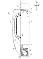
図1に示される車両用ドアハンドル装置(以下、単に「ドアハンドル装置」ともいう)100は、車両ドアに組付けられるものであり、ベースフレーム110、アウトサイドハンドル120及び軸受部材150を含む複数の構成部品が一体状に組み付けられたアセンブリ(「アッシー」ともいう)として構成されている。
(First embodiment)
A vehicle door handle device (hereinafter also simply referred to as “door handle device”) 100 shown in FIG. 1 is assembled to a vehicle door, and includes a plurality of base frames 110, an
ベースフレーム110は、車両前後方向X1,X2に沿って長尺状に延在する部材であり、車両ドアの外表面を構成する金属製のドアアウタパネル10の車内側に設けられる。このベースフレーム110は、アウトサイドハンドル120と係合することによって当該アウトサイドハンドル120を保持する機能を果たす。このベースフレーム110が本発明の「ベースフレーム」に相当する。ベースフレーム110の前端側(図1中の左側)の部位には開口部111が開口形成され、ベースフレーム110の後端側(図1中の右側)の部位には開口部112が開口形成されている。
The
第1の実施形態のアウトサイドハンドル(以下、単に「ハンドル」ともいう)120は、ベースフレーム110と同様に車両前後方向X1,X2に沿って長尺状に延在し一方端及び他方端を備えるグリップ型のハンドル部分であり、樹脂材料によって構成されている。このアウトサイドハンドル120が本発明の「アウトサイドハンドル」に相当する。ユーザはこのハンドル120を手指で把持して車両ドアの開閉操作を行うことができる。このハンドル120は、ドアアウタパネル10に取り付けられた状態で、車外側(図1中の上側)に配置される樹脂製の第1ハンドル部材(「アッパー部材」ともいう)130と車内側(図1中の下側)に配置される樹脂製の第2ハンドル部材(「ロア部材」ともいう)140の2つの部材が所定の固定機構(以下、単に「固定機構」ともいう)170を介して一体状に固定された構造、所謂「ツーピース構造」を有する。ここでいう第1ハンドル部材130及び第2ハンドル部材140がそれぞれ、本発明の「第1ハンドル部材」及び「第2ハンドル部材」に相当する。
The outside handle (hereinafter, also simply referred to as “handle”) 120 of the first embodiment extends in a long shape along the vehicle longitudinal direction X1, X2 like the
ハンドル120は、ドアアウタパネル10に開口形成された開口部(図示省略)及びベースフレーム110の開口部111,112を通じて車外側から車内側に突出し、この突出部分においてベースフレーム110に取付けられる。ハンドル120の第2ハンドル部材140のうちハンドル前端側の部位(一方端側の部位)にはベースフレーム110の開口部111に挿入される係合アーム141が設けられている。係合アーム141は、車両上下方向に延在する円柱状のハンドル軸部141aを備え、このハンドル軸部141aにおいて、ベースフレーム110に一体状に組付けられた軸受部材150に回動可能に取付けられる。即ち、ハンドル軸部141aがハンドル120のハンドル回動中心となる。一方で、ハンドル120の第2ハンドル部材140のうちハンドル後端側の部位(他方端側の部位)にはベースフレーム110の開口部112に挿入される、略L字状の断面形状の係合脚部142が設けられている。係合脚部142は、ハンドル120が開操作されたときの最大回動位置(フルストローク位置)を定めるハンドルストッパとしての機能を果たす。
The
図2及び図3が参照されるように、上記の固定機構170は、第1ハンドル部材130にその内壁面131から第2ハンドル部材140に向けて突出するように設けられた台座部132と、第2ハンドル部材140のボス部143から台座部132に向けて延出するように設けられた一対の係合爪145,145と、セルフタッピングスクリュー(以下、単に「スクリュー」ともいう)160と、によって構成されている。この固定機構170が本発明の「固定機構」に相当する。
As shown in FIGS. 2 and 3, the
台座部132は、一対の係合爪145,145が係合可能(挿入可能)となるように開口形成された係合穴133と、係合穴133に係合した係合状態(挿入状態)の一対の係合爪145,145の先端部分を収容するために一対の立設壁が対向する対向空間(「収容空間」ともいう)134とを備えた形状(「ボックス形状」ともいう)になっている。この台座部132が本発明の「台座部」に相当する。また、この台座部132の係合穴133は、第2ハンドル部材140側の一対の係合爪145,145が係合する凹状の部位であり、本発明の「係合穴」に相当する。
The
一対の係合爪145,145は、車両上下方向Z1,Z2についてスクリュー160の雄ネジ部160aを挿入可能な所定の空間146を隔てて互いに対向配置されている。図3に示される初期状態の第2ハンドル部材140では、一対の係合爪145,145は、ボス部143のうち貫通孔144を挟んでその縁部から車両外方Y1に平行に延出している。各係合爪145は、平板状に構成された延出部145aの先端に延出部145aよりも板厚が拡張された爪部145bを備えている。この場合、第2ハンドル部材140は樹脂材料によって構成されているため、一対の係合爪145,145は互いに近接する方向及び離間する方向に弾性変形可能である。これら一対の係合爪145が本発明の「複数の係合爪」に相当する。尚、一対の係合爪145,145は、車両前後方向X1,X2について対向配置されるように構成されてもよい。また、係合爪145の設置数は2つに限定されるものではなく、必要に応じて2つ以上に増やすことができる。
The pair of engaging
スクリュー160は、係合対象部分に予め雌ネジ部が形成されていなくても自身の捩じ込み動作によって雄ネジ部160aが雌ネジ部を形成することが可能な金属製の既知のネジ部材である。このスクリュー160は、ボス部143に貫通形成された貫通孔144に挿入され、更に一対の係合爪145,145の間の空間146に挿入される。従って、本実施の形態では、貫通孔144の内壁面及び各係合爪145の対向壁面145cは、スクリュー160の捩じ込み動作によって雌ネジ部が形成される部位となる。このセルフタッピングスクリュー160が本発明の「ネジ部材」及び「ストッパ部材」に相当する。尚、セルフタッピングスクリュー160に代えて、係合対象部分に予め形成された雌ネジ部に螺合可能な雄ネジ部を有する金属製の各種のネジ部材を用いることもできる。
The
図4〜図6が参照されるように、第1ハンドル部材130と第2ハンドル部材140を一体状に固定する場合、まず第1ハンドル部材130の台座部132に開口形成された係合穴133に第2ハンドル部材140の一対の係合爪145,145を挿入する。この場合、台座部132の係合穴133の内壁面には、各係合爪145の爪部145bが引っ掛かるように突出した係合突起135が設けられている(図6参照)。このため、一対の係合爪145,145は、係合穴133に挿入される過程で係合突起135,135によって押圧されて図3の初期状態から互いに近接する方向に弾性変形する。図6に示されるように、台座部132の係合穴133に一対の係合爪145,145が挿入された後は、各係合爪145の爪部145bが各係合突起135に引っ掛かることによって、台座部132に対して一対の係合爪145,145が保持された仮保持状態になる。この場合、係合穴133に係合した係合状態の一対の係合爪145,145の先端部分は、台座部132の対向空間134に収容される。
As shown in FIGS. 4 to 6, when the
その後、一対の係合爪145,145が台座部132の係合穴133に係合した係合状態で、スクリュー160が第2ハンドル部材140の貫通孔144に挿入されつつ捩じ込まれることによって、その雄ネジ部160aが貫通孔144の内壁面に雌ネジ部を形成しながら当該雌ネジ部に螺合する。更に、このスクリュー160が捩じ込まれると、その雄ネジ部160aが各係合爪145の対向壁面145cに雌ネジ部を形成しながら当該雌ネジ部に螺合する。その結果、図7に示されるように、スクリュー160は、各係合爪145の対向壁面145cに捩じ込まれて一対の係合爪145,145に係止される。これにより、一対の係合爪145,145の間の空間146にスクリュー160の雄ネジ部160aが介在することとなり、一対の係合爪145,145は互いに近接する方向(即ち、係合解除方向)への弾性変形がスクリュー160によって規制されて、各係合爪145の爪部145bと係合穴133との係合が維持される。この場合、スクリュー160の雄ネジ部160aは、係合穴133に係合した各係合爪145の係合解除方向への弾性変形を規制する機能を果たす。これにより、2つのハンドル部材130,140の固定状態が維持される。
After that, the
第1ハンドル部材130と第2ハンドル部材140は固定機構170を用いて一体状に固定される結果、ナット部材及びボルト部材の締結による固定機構を用いた場合と同様の強度を得ることができる。この固定機構170では、2つのハンドル部材130,140を固定するのにこれら2つのハンドル部材130,140以外にスクリュー160のみを準備すればよい。従って、第1ハンドル部材130に溶着やインサート成型によって取付けられた金属製のナット部材に対して、第2ハンドル部材140の挿入孔に挿入された金属製のボルト部材を螺合させるような固定機構を採用する場合に比べて部品点数を減らすことができる。この場合、ナット部材の取付けのための工数が必要ない。その結果、2つのハンドル部材130,140を固定するための固定機構に要するコストを低く抑えることができる。また、対向空間134に収容された一対の係合爪145,145の先端部分は台座部132の壁面によって保護されるため、一対の係合爪145,145に係合解除のための荷重が作用するのを防止できる。
As a result of the
また、上記の固定機構170によれば、スクリュー160は車内側の第2ハンドル部材140に捩じ込まれる。従って、塗装やメッキに適した樹脂材料(典型的には、ポリカーボネート系の樹脂材料(非晶性樹脂))によって構成されるのが一般的である車外側の第1ハンドル部材130に対してスクリュー160を捩じ込む必要がない。その結果、第1ハンドル部材130にポリカーボネート系の樹脂材料を使用しても割れ等の問題を気にすることなく2つのハンドル部材130,140を確実に固定することができる。
Further, according to the
(第2の実施形態)
図8に示されるように、第2の実施形態のハンドル220は、第1ハンドル部材130と同様の第1ハンドル部材230と、第2ハンドル部材140と同様の第2ハンドル部材240とを備えている。第2ハンドル部材240は、一対の係合爪145,145に類似の一対の係合爪245,245を備えている。ここでいう第1ハンドル部材230及び第2ハンドル部材240がそれぞれ、本発明の「第1ハンドル部材」及び「第2ハンドル部材」に相当する。また、このハンドル220は、第1ハンドル部材230及び第2ハンドル部材240に加えて、第1ハンドル部材230と第2ハンドル部材240との間に介装されるアンテナユニット250を備えている。
(Second Embodiment)
As shown in FIG. 8, the
アンテナユニット250は、既知の構造を有するため特に詳細な説明は省略するが、ロックセンサ電極251及びアンテナアッシ252を備えている。ロックセンサ電極251は、第1ハンドル部材230に組付けられる金属板片状の部材であり、第1ハンドル部材230にユーザの手が触れたことを静電容量の変化によって電磁気的に検知する機能を果たす。ロックセンサ電極251は、アンテナアッシ252の電極(図13中のアンテナアッシ電極252a)に接続されている。アンテナアッシ252は、ユーザがハンドル220を開操作するための動作を静電容量の変化によって電磁気的に検知する機能を果たす。アンテナユニット250の樹脂製のユニット本体250aには、第2ハンドル部材240の一対の係合爪245,245を挿入するための貫通孔250bが貫通形成されている。
The
図9に示されるように、第1ハンドル部材230は、台座部132と同様の機能を果たす台座部232を備えている。この台座部232が本発明の「台座部」に相当する。台座部232は、第2ハンドル部材240側の一対の係合爪245,245が係合可能(挿入可能)となるように係合穴233が開口形成されたボッスク形状を有する。この台座部232が本発明の「台座部」に相当する。また、この台座部232の係合穴233は一対の係合爪245,245が係合する凹状の部位であり、本発明の「係合穴」に相当する。係合穴233では、車両前後方向X1,X2についての両端部のそれぞれに曲面233aが設けられている。この曲面233aは、係合穴233に挿入された各係合爪245の湾曲表面(図12中の湾曲表面245c)に倣った形状になっている。これにより、係合穴233に一対の係合爪245,245が挿入された状態では、係合穴233の曲面233aと各係合爪245の湾曲表面とが面接触する結果、第1ハンドル部材230に対する第2ハンドル部材240の位置決めを容易に行うことが可能になる。
As shown in FIG. 9, the
図9〜図11を参照しつつより具体的に説明すると、台座部232は、一対の立設壁232a,232bと連結壁232cとを備えている。一対の立設壁232a,232bは、台座部232のうちハンドル220の長尺延在方向である車両前後方向X1,X2に沿って互いに平行に且つ第2ハンドル部材240に向けて立設された部位である。この台座部232では、一対の立設壁232a,232bが対向することによって区画された対向空間(「収容空間」ともいう)234に係合穴233に係合した一対の係合爪245,245を収容する。連結壁232cは、台座部232のうち一対の立設壁232a,232bを連結し且つ一対の立設壁232a,232bの間に係合穴233を有する部位である。ここでいう一対の立設壁232a,232b及び連結壁232cがそれぞれ本発明の「一対の立設壁」及び「連結壁」に相当する。
Describing more specifically with reference to FIGS. 9 to 11, the
尚、台座部232を備えた第1ハンドル部材230は樹脂成型によって形成されるのが好ましい。この場合、第1ハンドル部材230の台座部232に係合穴233のような中空部を形成するべく、樹脂成型用の金型にピンやコアなどの凸部を設けた場合には、樹脂成型時にその凸部において分流した溶融樹脂は分流後に再び合流して融着した部位に細い線(ウェルドラインWL)を形成する。このウェルドラインWLの部位は密着強度が弱く台座部232が割れ易いことが知られている。
In addition, it is preferable that the
そこで、台座部232では、特に図10及び図11が参照されるように、一対の立設壁232a,232bが樹脂成型時の溶融樹脂が流れる樹脂流れ方向(図10中のFで示される方向)に沿って延在し、一方の立設壁232aと他方の立設壁232bとで樹脂流れ方向Fと交差する方向(車両上下方向Z1,Z2)についての壁厚が異なるのが好ましい。図10及び図11に示す実施例では、一方の立設壁232aの壁厚d1が他方の立設壁232bの壁厚d2を上回るように構成されている。本構成によれば、一方の立設壁232aの壁厚d1と他方の立設壁232bの壁厚d2を変えることによって、即ち樹脂成型時に金型のうち一方の立設壁232aに対応した部位を流れる溶融樹脂と他方の立設壁232bに対応した部位を流れる溶融樹脂とで流れる速度を変えることによって、ウェルドラインWLの位置を2つの立設壁232a,232bの中間地点から車両上下方向Z1,Z2についていずれか一方の立設壁寄りにずらすことができる。その結果、ウェルドラインWLが中間地点よりも強度の高い位置(いずれか一方の立設壁に近い位置)に形成されるため台座部232が割れにくくなる。
Therefore, in the
図12に示されるように、第2ハンドル部材240は、一対の係合爪145,145と同様の機能を果たす係合爪245,245を備えている。一対の係合爪245,245は、車両前後方向X1,X2について樹脂製のピン260の軸部260aを挿入可能な所定の空間246を隔てて互いに対向配置されている。一対の係合爪245,245は、ボス部243のうち貫通孔244を挟んでその縁部から車両外方Y1に平行に延出している。各係合爪245は、湾曲板状に構成された延出部245aの先端に延出部245aよりも板厚が拡張された爪部245bを備えている。この場合、第2ハンドル部材240は樹脂材料によって構成されているため、一対の係合爪245,245は互いに近接する方向及び離間する方向に弾性変形可能である。これら一対の係合爪245が本発明の「複数の係合爪」に相当する。尚、一対の係合爪245,245は、車両上下方向Z1,Z2について対向配置されるように構成されてもよい。また、係合爪245の設置数は2つに限定されるものではなく、必要に応じて2つ以上に増やすことができる。
As shown in FIG. 12, the
図13に示されるように、上記構成のハンドル220では、第1ハンドル部材230と第2ハンドル部材240の2つの部材が固定機構270を用いて一体状に固定される。この固定機構270が本発明の「固定機構」に相当する。固定機構270は、第1ハンドル部材230にその内壁面231から第2ハンドル部材240に向けて突出するように設けられた台座部232と、第2ハンドル部材240のボス部243から台座部232に向けて延出するように設けられた一対の係合爪245,245と、樹脂製のピン260と、によって構成されている。
As shown in FIG. 13, in the
第1ハンドル部材230と第2ハンドル部材240を一体状に固定する場合、まず第2ハンドル部材240の一対の係合爪245,245がアンテナユニット250の貫通孔250bに挿入されるようにして、第2ハンドル部材240にアンテナユニット250を予め組付ける。その後、第1ハンドル部材230の台座部232に開口形成された係合穴233に第2ハンドル部材240の一対の係合爪245,245を挿入する。この場合、台座部232に各係合爪245の爪部245bが引っ掛かることによって、台座部232に対して一対の係合爪245,245が保持された仮保持状態になる。その後、一対の係合爪245,245が台座部232の係合穴233に係合した係合状態で、ピン260が第2ハンドル部材240の貫通孔244に挿入され、更に一対の係合爪245,245の間の空間246に挿入されることによって一対の係合爪245,245に係止される。このピン260が本発明の「ピン」及び「ストッパ部材」に相当する。
When the
これにより、一対の係合爪245,245の間の空間246にピン260の軸部260aが介在することとなり、一対の係合爪245,245は互いに近接する方向(即ち、係合解除方向)への弾性変形がピン260によって規制されて、各係合爪245と係合穴233との係合が維持される。この場合、ピン260の軸部260aは、係合穴233に係合した各係合爪245の係合解除方向への弾性変形を規制する機能を果たす。その結果、2つのハンドル部材230,240の固定状態が維持される。また、対向空間234に収容された一対の係合爪245,245の先端部分は台座部232の壁面に(立設壁232a,232b)よって保護されるため、一対の係合爪245,245に係合解除のための荷重が作用するのを防止できる。
As a result, the
このハンドル220では、2つのハンドル部材230,240の固定状態において、ロックセンサ電極251とアンテナアッシ電極252aとの双方は、互いに接触した状態で第1ハンドル部材230の台座部232と第2ハンドル部材240のボス部243とによって挟み込まれるように構成されている。即ち、第1ハンドル部材230に予め組付けられたロックセンサ電極251と、第2ハンドル部材240に予め組付けられたアンテナアッシ電極252aが互いに接触する。これにより、2つのハンドル部材230,240を固定するのみで、ロックセンサ電極251とアンテナアッシ電極252aとの接点を容易に確保することができる。
In the
上記構成の固定機構270を用いる場合も、固定機構170を用いる場合と同様に、2つのハンドル部材230,240を固定するのにこれら2つのハンドル部材230,240以外にピン260のみを準備すればよい。この場合、ナット部材に相当する部品が必要ないため、当該部品自体の費用や当該部品を溶着やインサート成型によって取付ける工数が発生することがなくコスト低減効果が得られる。特に、比較的安価な樹脂製のピン260を用いることでストッパ部材の部品コストを低く抑えることができる。
When the
本発明は、上記の典型的な実施形態のみに限定されるものではなく、種々の応用や変形が考えられる。例えば、上記実施の形態を応用した次の各形態を実施することもできる。 The present invention is not limited to the above exemplary embodiment, and various applications and modifications are possible. For example, each of the following embodiments to which the above embodiment is applied can be implemented.
上記の実施形態の固定機構170,270では、車内側の第2ハンドル部材140,240から車外側の第1ハンドル部材130,230に向けて延出した係合爪145,245が第1ハンドル部材130,230の台座部132,232に係合する場合について記載したが、本発明では、車外側の第1ハンドル部材130,230に係合爪145,245を設け、車内側の第2ハンドル部材140,240に台座部132,232を設けた構造を採用することもできる。
In the fixing
本発明では、上記構成のドアハンドル装置100の本質的な構造を車両の各車両ドアに適用することができる。例えば、車両前席用の左右のドアや、車両後席用の左右のドア、更には車両後部のドア(バックドア)等にドアハンドル装置100の本質的な構造を適用することもできる。
In the present invention, the essential structure of the
10…ドアアウタパネル、100…車両用ドアハンドル装置、110…ベースフレーム、120,220…アウトサイドハンドル、130,230…第1ハンドル部材、132,232…台座部、133,233…係合穴、134,234…対向空間、140,240…第2ハンドル部材、145,245…係合爪、150…軸受部材、160…セルフタッピングスクリュー(ストッパ部材)、170,270…固定機構、250…アンテナユニット、260…ピン(ストッパ部材)
DESCRIPTION OF
Claims (5)
前記車両ドアの外表面を構成するドアアウタパネルの車内側に設けられるベースフレームと、
車外側の樹脂製の第1ハンドル部材と車内側の樹脂製の第2ハンドル部材が固定機構を介して一体状に固定されることによって構成され、前記ドアアウタパネルの車外側から前記ベースフレームに取付けられるアウトサイドハンドルと、
を含み、
前記固定機構は、前記第1ハンドル部材及び前記第2ハンドル部材のうちの一方のハンドル部材に設けられ所定の空間を隔てて互いに対向配置された複数の係合爪と、前記第1ハンドル部材及び前記第2ハンドル部材のうちの他方のハンドル部材に設けられ前記複数の係合爪を挿入可能な係合穴を有する台座部と、前記台座部の前記係合穴に挿入された状態の前記複数の係合爪の間の前記空間に挿入されるストッパ部材と、によって構成され、
前記台座部は、前記他方のハンドル部材から前記一方のハンドル部材に向けて立設された一対の立設壁と、前記一対の立設壁を連結し且つ前記一対の立設壁の間に前記係合穴を有する連結壁と、を備え、前記一対の立設壁が対向する対向空間に前記係合穴に挿入された状態の前記複数の係合爪を収容する、車両用ドアハンドル装置。 A vehicle door handle device assembled to a vehicle door,
A base frame provided on the vehicle inner side of the door outer panel constituting the outer surface of the vehicle door;
A first handle member made of resin on the outside of the vehicle and a second handle member made of resin on the inside of the vehicle are integrally fixed via a fixing mechanism, and are attached to the base frame from the vehicle outer side of the door outer panel. An outside handle,
Including
The fixing mechanism includes a plurality of engaging claws provided on one handle member of the first handle member and the second handle member and arranged to face each other with a predetermined space therebetween, the first handle member, A pedestal portion having an engagement hole into which the plurality of engagement claws can be inserted provided on the other handle member of the second handle member, and the plurality of the state in which the plurality of engagement portions are inserted into the engagement holes of the pedestal portion a stopper member that is inserted into the space between the engaging claws are constituted by,
The pedestal portion connects a pair of standing walls standing from the other handle member toward the one handle member, and the pair of standing walls, and between the pair of standing walls, A vehicular door handle device , wherein the plurality of engaging claws in a state of being inserted into the engaging holes are accommodated in a facing space where the pair of standing walls oppose each other .
前記ストッパ部材は、前記台座部の前記係合穴に挿入された状態の前記複数の係合爪の間の前記空間に捩じ込みによって挿入される金属製のネジ部材として構成されている、車両用ドアハンドル装置。 The vehicle door handle device according to claim 1,
Before SL stopper member is formed as a metallic screw member which is inserted by screwing into the space between the plurality of engaging claws of the engagement state of being inserted into engagement holes of the base portion, Vehicle door handle device.
前記ストッパ部材は、前記台座部の前記係合穴に挿入された状態の前記複数の係合爪の間の前記空間に挿入される樹脂製のピンとして構成されている、車両用ドアハンドル装置。 The vehicle door handle device according to claim 1,
Before SL stopper member, the is configured as a pin made of resin which is inserted into the space between the plurality of engaging claws of the engagement state of being inserted into engagement hole of the base portion, the vehicle door handle device .
前記固定機構は、前記一方のハンドル部材としての前記第2ハンドル部材から前記他方のハンドル部材としての前記第1ハンドル部材に向けて延出した前記複数の係合爪が前記第1ハンドル部材に設けられた前記台座部の前記係合穴に係合するように構成されている、車両用ドアハンドル装置。 The vehicle door handle device according to any one of claims 1 to 3,
The fixing mechanism is provided with the plurality of engaging claws extending from the second handle member as the one handle member toward the first handle member as the other handle member. A vehicle door handle device configured to engage with the engagement hole of the pedestal portion .
前記台座部は、前記一対の立設壁が樹脂成型時の溶融樹脂が流れる樹脂流れ方向に沿って延在し、前記一対の立設壁のうちの一方の立設壁と他方の立設壁とで前記樹脂流れ方向と交差する方向についての壁厚が異なる、車両用ドアハンドル装置。
The vehicle door handle device according to any one of claims 1 to 4,
The pedestal portion extends along a resin flow direction in which the pair of standing walls flows through a molten resin during resin molding, and one of the pair of standing walls and the other standing wall The vehicle door handle device has a different wall thickness in a direction intersecting the resin flow direction.
Priority Applications (5)
| Application Number | Priority Date | Filing Date | Title |
|---|---|---|---|
| JP2014201013A JP6388121B2 (en) | 2014-09-30 | 2014-09-30 | Vehicle door handle device |
| EP15845878.6A EP3203003B1 (en) | 2014-09-30 | 2015-09-24 | Vehicle door handle device |
| PCT/JP2015/076864 WO2016052286A1 (en) | 2014-09-30 | 2015-09-24 | Vehicle door handle device |
| US15/513,470 US10280656B2 (en) | 2014-09-30 | 2015-09-24 | Door handle apparatus for vehicle |
| CN201590001021.3U CN206844876U (en) | 2014-09-30 | 2015-09-24 | Door handle device for vehicle |
Applications Claiming Priority (1)
| Application Number | Priority Date | Filing Date | Title |
|---|---|---|---|
| JP2014201013A JP6388121B2 (en) | 2014-09-30 | 2014-09-30 | Vehicle door handle device |
Publications (2)
| Publication Number | Publication Date |
|---|---|
| JP2016069945A JP2016069945A (en) | 2016-05-09 |
| JP6388121B2 true JP6388121B2 (en) | 2018-09-12 |
Family
ID=55630326
Family Applications (1)
| Application Number | Title | Priority Date | Filing Date |
|---|---|---|---|
| JP2014201013A Active JP6388121B2 (en) | 2014-09-30 | 2014-09-30 | Vehicle door handle device |
Country Status (5)
| Country | Link |
|---|---|
| US (1) | US10280656B2 (en) |
| EP (1) | EP3203003B1 (en) |
| JP (1) | JP6388121B2 (en) |
| CN (1) | CN206844876U (en) |
| WO (1) | WO2016052286A1 (en) |
Families Citing this family (5)
| Publication number | Priority date | Publication date | Assignee | Title |
|---|---|---|---|---|
| JP6064806B2 (en) * | 2013-06-21 | 2017-01-25 | アイシン精機株式会社 | Vehicle door handle |
| JP6304209B2 (en) * | 2015-11-30 | 2018-04-04 | アイシン精機株式会社 | Vehicle handle device |
| JP7207191B2 (en) * | 2019-06-19 | 2023-01-18 | 株式会社アイシン | VEHICLE DOOR HANDLE DEVICE AND METHOD OF FIXING ELECTRONIC CIRCUIT DEVICE FOR VEHICLE DOOR HANDLE DEVICE |
| CN112937400B (en) * | 2021-03-15 | 2022-08-09 | 重庆长安汽车股份有限公司 | Integral type vehicle door vertical armrest mounting structure |
| JP2022186074A (en) * | 2021-06-04 | 2022-12-15 | 株式会社アルファ | Steering wheel device for vehicles |
Family Cites Families (10)
| Publication number | Priority date | Publication date | Assignee | Title |
|---|---|---|---|---|
| FR2633020B1 (en) * | 1988-06-21 | 1990-08-10 | Peugeot | SYSTEM FOR FIXING A TRIM AND A MEMBER SUCH AS A HANDLE ON A BODY PANEL |
| JP2605319Y2 (en) * | 1993-03-31 | 2000-07-10 | 株式会社アルファ | Door handle device |
| JP4323641B2 (en) * | 1999-10-22 | 2009-09-02 | 株式会社ニフコ | Parts mounting device |
| JP3762227B2 (en) * | 2001-01-25 | 2006-04-05 | シロキ工業株式会社 | Handle mechanism for unlocking |
| CN201130719Y (en) * | 2007-11-16 | 2008-10-08 | 富士康(昆山)电脑接插件有限公司 | Cable connector |
| JP5162617B2 (en) * | 2010-04-15 | 2013-03-13 | 株式会社ホンダロック | Outdoor handle device for vehicle door |
| JP5022483B2 (en) | 2010-07-26 | 2012-09-12 | アイシン精機株式会社 | Vehicle door handle device |
| WO2012151403A1 (en) * | 2011-05-04 | 2012-11-08 | Illinois Tool Works Inc. | An assembly for mounting a handle on a vehicle door |
| JP5580263B2 (en) * | 2011-08-23 | 2014-08-27 | 株式会社ホンダロック | Outdoor handle device for vehicle door |
| JP2014111980A (en) * | 2012-11-12 | 2014-06-19 | Kitagawa Kogyo Co Ltd | Screw |
-
2014
- 2014-09-30 JP JP2014201013A patent/JP6388121B2/en active Active
-
2015
- 2015-09-24 US US15/513,470 patent/US10280656B2/en active Active
- 2015-09-24 EP EP15845878.6A patent/EP3203003B1/en active Active
- 2015-09-24 CN CN201590001021.3U patent/CN206844876U/en active Active
- 2015-09-24 WO PCT/JP2015/076864 patent/WO2016052286A1/en active Application Filing
Also Published As
| Publication number | Publication date |
|---|---|
| WO2016052286A1 (en) | 2016-04-07 |
| CN206844876U (en) | 2018-01-05 |
| EP3203003A1 (en) | 2017-08-09 |
| EP3203003B1 (en) | 2019-01-30 |
| JP2016069945A (en) | 2016-05-09 |
| US20170298660A1 (en) | 2017-10-19 |
| US10280656B2 (en) | 2019-05-07 |
| EP3203003A4 (en) | 2017-09-13 |
Similar Documents
| Publication | Publication Date | Title |
|---|---|---|
| JP6388121B2 (en) | Vehicle door handle device | |
| JP6049390B2 (en) | Vehicle back door | |
| US8950782B2 (en) | Mounting device for securing a seat belt buckle | |
| JP5633994B2 (en) | Resin door structure for vehicles | |
| RU2628273C1 (en) | Radiator grille | |
| US9630573B2 (en) | Clip mounting seats of interior components or exterior components | |
| US10220748B2 (en) | Vehicular interior part | |
| US9132748B2 (en) | Seat back mounting structure of vehicle body | |
| JP6147803B2 (en) | Vehicle structure | |
| US20160230428A1 (en) | Inside door handle assembly for vehicle | |
| JP5210670B2 (en) | Engagement structure and automotive interior member provided with the same | |
| JP2013007158A (en) | Door handlebar for vehicle | |
| US10081394B2 (en) | Mounting structure of vehicular resin component | |
| JP6014820B2 (en) | Vehicle under cover assembly structure | |
| KR20160142505A (en) | Device for supporting fastner in car | |
| JP4858455B2 (en) | Wall and door connection structure | |
| JP6884463B2 (en) | back door | |
| CN108001377B (en) | Fixing structure of vehicle interior trim | |
| JP6272937B2 (en) | Cover member | |
| JP2015196985A (en) | Vehicle door handle device | |
| JP2015039996A (en) | Back door for automobile | |
| JP7245590B2 (en) | vehicle back door | |
| JP5833899B2 (en) | Auxiliary mirror fixing structure | |
| US10179501B2 (en) | Door structure for vehicle | |
| JP4857229B2 (en) | Mounting structure of support holder |
Legal Events
| Date | Code | Title | Description |
|---|---|---|---|
| A621 | Written request for application examination |
Free format text: JAPANESE INTERMEDIATE CODE: A621 Effective date: 20170123 |
|
| A131 | Notification of reasons for refusal |
Free format text: JAPANESE INTERMEDIATE CODE: A131 Effective date: 20180130 |
|
| A521 | Request for written amendment filed |
Free format text: JAPANESE INTERMEDIATE CODE: A523 Effective date: 20180330 |
|
| TRDD | Decision of grant or rejection written | ||
| A01 | Written decision to grant a patent or to grant a registration (utility model) |
Free format text: JAPANESE INTERMEDIATE CODE: A01 Effective date: 20180718 |
|
| A61 | First payment of annual fees (during grant procedure) |
Free format text: JAPANESE INTERMEDIATE CODE: A61 Effective date: 20180731 |
|
| R151 | Written notification of patent or utility model registration |
Ref document number: 6388121 Country of ref document: JP Free format text: JAPANESE INTERMEDIATE CODE: R151 |