JP6386806B2 - Image forming apparatus and developing unit - Google Patents
Image forming apparatus and developing unit Download PDFInfo
- Publication number
- JP6386806B2 JP6386806B2 JP2014127490A JP2014127490A JP6386806B2 JP 6386806 B2 JP6386806 B2 JP 6386806B2 JP 2014127490 A JP2014127490 A JP 2014127490A JP 2014127490 A JP2014127490 A JP 2014127490A JP 6386806 B2 JP6386806 B2 JP 6386806B2
- Authority
- JP
- Japan
- Prior art keywords
- unit
- image carrier
- forming apparatus
- image
- developing
- Prior art date
- Legal status (The legal status is an assumption and is not a legal conclusion. Google has not performed a legal analysis and makes no representation as to the accuracy of the status listed.)
- Active
Links
- 230000009471 action Effects 0.000 claims description 17
- 230000015572 biosynthetic process Effects 0.000 claims description 13
- 238000010977 unit operation Methods 0.000 claims description 4
- 239000000969 carrier Substances 0.000 claims 1
- 238000000926 separation method Methods 0.000 description 77
- 238000000034 method Methods 0.000 description 62
- 230000008569 process Effects 0.000 description 62
- 238000013459 approach Methods 0.000 description 5
- 230000005484 gravity Effects 0.000 description 5
- 238000004140 cleaning Methods 0.000 description 4
- 125000006850 spacer group Chemical group 0.000 description 4
- 239000003086 colorant Substances 0.000 description 3
- 230000002093 peripheral effect Effects 0.000 description 3
- 230000032258 transport Effects 0.000 description 2
- XAGFODPZIPBFFR-UHFFFAOYSA-N aluminium Chemical compound [Al] XAGFODPZIPBFFR-UHFFFAOYSA-N 0.000 description 1
- 229910052782 aluminium Inorganic materials 0.000 description 1
- 230000008859 change Effects 0.000 description 1
- 239000004020 conductor Substances 0.000 description 1
- 230000008878 coupling Effects 0.000 description 1
- 238000010168 coupling process Methods 0.000 description 1
- 238000005859 coupling reaction Methods 0.000 description 1
- 230000000694 effects Effects 0.000 description 1
- 230000005684 electric field Effects 0.000 description 1
- 238000010438 heat treatment Methods 0.000 description 1
- 230000003287 optical effect Effects 0.000 description 1
- 238000003825 pressing Methods 0.000 description 1
Images


Classifications
-
- G—PHYSICS
- G03—PHOTOGRAPHY; CINEMATOGRAPHY; ANALOGOUS TECHNIQUES USING WAVES OTHER THAN OPTICAL WAVES; ELECTROGRAPHY; HOLOGRAPHY
- G03G—ELECTROGRAPHY; ELECTROPHOTOGRAPHY; MAGNETOGRAPHY
- G03G21/00—Arrangements not provided for by groups G03G13/00 - G03G19/00, e.g. cleaning, elimination of residual charge
- G03G21/16—Mechanical means for facilitating the maintenance of the apparatus, e.g. modular arrangements
- G03G21/1642—Mechanical means for facilitating the maintenance of the apparatus, e.g. modular arrangements for connecting the different parts of the apparatus
- G03G21/1647—Mechanical connection means
-
- G—PHYSICS
- G03—PHOTOGRAPHY; CINEMATOGRAPHY; ANALOGOUS TECHNIQUES USING WAVES OTHER THAN OPTICAL WAVES; ELECTROGRAPHY; HOLOGRAPHY
- G03G—ELECTROGRAPHY; ELECTROPHOTOGRAPHY; MAGNETOGRAPHY
- G03G21/00—Arrangements not provided for by groups G03G13/00 - G03G19/00, e.g. cleaning, elimination of residual charge
- G03G21/16—Mechanical means for facilitating the maintenance of the apparatus, e.g. modular arrangements
- G03G21/1604—Arrangement or disposition of the entire apparatus
- G03G21/1623—Means to access the interior of the apparatus
- G03G21/1633—Means to access the interior of the apparatus using doors or covers
-
- G—PHYSICS
- G03—PHOTOGRAPHY; CINEMATOGRAPHY; ANALOGOUS TECHNIQUES USING WAVES OTHER THAN OPTICAL WAVES; ELECTROGRAPHY; HOLOGRAPHY
- G03G—ELECTROGRAPHY; ELECTROPHOTOGRAPHY; MAGNETOGRAPHY
- G03G21/00—Arrangements not provided for by groups G03G13/00 - G03G19/00, e.g. cleaning, elimination of residual charge
- G03G21/16—Mechanical means for facilitating the maintenance of the apparatus, e.g. modular arrangements
- G03G21/1661—Mechanical means for facilitating the maintenance of the apparatus, e.g. modular arrangements means for handling parts of the apparatus in the apparatus
- G03G21/1666—Mechanical means for facilitating the maintenance of the apparatus, e.g. modular arrangements means for handling parts of the apparatus in the apparatus for the exposure unit
-
- G—PHYSICS
- G03—PHOTOGRAPHY; CINEMATOGRAPHY; ANALOGOUS TECHNIQUES USING WAVES OTHER THAN OPTICAL WAVES; ELECTROGRAPHY; HOLOGRAPHY
- G03G—ELECTROGRAPHY; ELECTROPHOTOGRAPHY; MAGNETOGRAPHY
- G03G21/00—Arrangements not provided for by groups G03G13/00 - G03G19/00, e.g. cleaning, elimination of residual charge
- G03G21/16—Mechanical means for facilitating the maintenance of the apparatus, e.g. modular arrangements
- G03G21/1661—Mechanical means for facilitating the maintenance of the apparatus, e.g. modular arrangements means for handling parts of the apparatus in the apparatus
- G03G21/1671—Mechanical means for facilitating the maintenance of the apparatus, e.g. modular arrangements means for handling parts of the apparatus in the apparatus for the photosensitive element
-
- G—PHYSICS
- G03—PHOTOGRAPHY; CINEMATOGRAPHY; ANALOGOUS TECHNIQUES USING WAVES OTHER THAN OPTICAL WAVES; ELECTROGRAPHY; HOLOGRAPHY
- G03G—ELECTROGRAPHY; ELECTROPHOTOGRAPHY; MAGNETOGRAPHY
- G03G21/00—Arrangements not provided for by groups G03G13/00 - G03G19/00, e.g. cleaning, elimination of residual charge
- G03G21/16—Mechanical means for facilitating the maintenance of the apparatus, e.g. modular arrangements
- G03G21/1661—Mechanical means for facilitating the maintenance of the apparatus, e.g. modular arrangements means for handling parts of the apparatus in the apparatus
- G03G21/1676—Mechanical means for facilitating the maintenance of the apparatus, e.g. modular arrangements means for handling parts of the apparatus in the apparatus for the developer unit
-
- G—PHYSICS
- G03—PHOTOGRAPHY; CINEMATOGRAPHY; ANALOGOUS TECHNIQUES USING WAVES OTHER THAN OPTICAL WAVES; ELECTROGRAPHY; HOLOGRAPHY
- G03G—ELECTROGRAPHY; ELECTROPHOTOGRAPHY; MAGNETOGRAPHY
- G03G2221/00—Processes not provided for by group G03G2215/00, e.g. cleaning or residual charge elimination
- G03G2221/16—Mechanical means for facilitating the maintenance of the apparatus, e.g. modular arrangements and complete machine concepts
- G03G2221/1651—Mechanical means for facilitating the maintenance of the apparatus, e.g. modular arrangements and complete machine concepts for connecting the different parts
- G03G2221/1654—Locks and means for positioning or alignment
-
- G—PHYSICS
- G03—PHOTOGRAPHY; CINEMATOGRAPHY; ANALOGOUS TECHNIQUES USING WAVES OTHER THAN OPTICAL WAVES; ELECTROGRAPHY; HOLOGRAPHY
- G03G—ELECTROGRAPHY; ELECTROPHOTOGRAPHY; MAGNETOGRAPHY
- G03G2221/00—Processes not provided for by group G03G2215/00, e.g. cleaning or residual charge elimination
- G03G2221/16—Mechanical means for facilitating the maintenance of the apparatus, e.g. modular arrangements and complete machine concepts
- G03G2221/1678—Frame structures
- G03G2221/1684—Frame structures using extractable subframes, e.g. on rails or hinges
Landscapes
- Physics & Mathematics (AREA)
- General Physics & Mathematics (AREA)
- Color Electrophotography (AREA)
- Electrophotography Configuration And Component (AREA)
- Exposure Or Original Feeding In Electrophotography (AREA)
- Electrostatic Charge, Transfer And Separation In Electrography (AREA)
Description
本発明は、記録媒体に画像を形成するための画像形成装置および画像形成装置の装置本体に着脱可能な現像ユニットに関するものである。 The present invention relates to an image forming apparatus for forming an image on a recording medium and a developing unit that can be attached to and detached from the main body of the image forming apparatus.
特許文献1には、現像カートリッジを支持した現像部ドロアが、画像形成装置の装置本体の内外を移動可能な構成である。そして画像形成装置のフロントカバーの開閉に連動して現像部ドロアが上下動させる構成が開示されている。つまりフロントカバーを開いた際には、現像部ドロアを上方に移動させて感光体ドラム1から離すことで、現像部ドロアを装置本体の外部に引き出せるようにしている。また現像部ドロアにはLEDアレイが設けられている。
Japanese Patent Application Laid-Open No. 2005-228561 has a configuration in which a developing unit drawer that supports a developing cartridge can move inside and outside the main body of the image forming apparatus. A configuration in which the developing unit drawer moves up and down in conjunction with opening and closing of the front cover of the image forming apparatus is disclosed. That is, when the front cover is opened, the developing unit drawer is moved upward and away from the
同様に特許文献1では感光体ドラムを支持する感光体ドロアがフロントカバーの開閉に連動して上下動する構成が開示されている。フロントカバーが開いた際には、感光体ドロアが搬送ベルトから離間し、感光体ドロアが装置本体の外部に引き出せるようになる。
Similarly,
上記特許文献1に記載された従来技術では、現像カートリッジや感光体ドラムを支持するドロア(支持部材)を本体装置のドアの開閉に連動して上下動させるために、ユーザがドアの開閉を行う際には大きな負荷がかかる。つまりユーザが各支持部材を操作する際の負荷が大きい。
In the prior art described in
そこで本発明は、ユーザが現像ユニット支持部材または像担持体ユニット支持部材を操作する際の負荷を軽減することを目的とする。 Accordingly, an object of the present invention is to reduce a load when a user operates a developing unit support member or an image carrier unit support member.
上記課題を解決するため、本発明は、記録媒体に画像を形成する画像形成装置において、像担持体を有する像担持体ユニットを取り外し可能に複数支持した状態で、前記画像形成装置の内部と外部との間を移動可能な像担持体ユニット支持部材と、像担持体ユニット支持部材から独立して移動可能な現像ユニット支持部材であって、対応する像担持体に形成された静電潜像を現像するための現像ユニットを取り外し可能に複数支持した状態で、前記画像形成装置の内部と外部の間を移動可能な現像ユニット支持部材と、それぞれ対応する像担持体を露光することで前記像担持体に静電潜像を形成する、前記現像ユニット支持部材に移動可能に支持された複数の露光ユニットと、前記現像ユニット支持部材が前記画像形成装置の内部にある際に、前記露光ユニットを前記現像ユニット支持部材に対して移動させ、画像形成するための位置よりも対応する前記像担持体から離す露光ユニット作用部材と、前記画像形成装置は、前記現像ユニット支持部材が前記画像形成装置の内部にある際に、前記現像ユニットを前記現像ユニット支持部材に対して移動させ、画像形成するための位置よりも対応する像担持体から離す現像ユニット作用部材と、を有することを特徴とする画像形成装置を提供する。或いは、記録媒体に画像を形成する画像形成装置において、像担持体を有する像担持体ユニットを取り外し可能に複数支持した状態で、前記画像形成装置の内部と外部との間を移動可能な像担持体ユニット支持部材と、像担持体ユニット支持部材から独立して移動可能な現像ユニット支持部材であって、対応する像担持体に形成された静電潜像を現像するための現像ユニットを取り外し可能に複数支持した状態で、前記画像形成装置の内部と外部の間を移動可能な現像ユニット支持部材と、それぞれ対応する像担持体を露光することで前記像担持体に静電潜像を形成する、前記現像ユニット支持部材に移動可能に支持された複数の露光ユニットと、前記現像ユニット支持部材が前記画像形成装置の内部にある際に、前記露光ユニットを前記現像ユニット支持部材に対して移動させ、画像形成するための位置よりも対応する前記像担持体から離す露光ユニット作用部材と、を有し、前記露光ユニット作用部材は、複数の露光ユニットの少なくとも一つを他の露光ユニットとは移動開始のタイミングを異ならせることを特徴とする画像形成装置を提供する。In order to solve the above problems, the present invention provides an image forming apparatus for forming an image on a recording medium, wherein a plurality of image carrier units each having an image carrier are detachably supported, and the inside and the outside of the image forming apparatus. An image carrier unit support member movable between the image carrier unit support member and a development unit support member movable independently from the image carrier unit support member, the electrostatic latent image formed on the corresponding image carrier In a state where a plurality of development units for developing are removably supported, the image carrier is exposed by exposing a development unit support member movable between the inside and the outside of the image forming apparatus and a corresponding image carrier. A plurality of exposure units that are movably supported by the development unit support member that forms an electrostatic latent image on the body, and the development unit support member is inside the image forming apparatus. An exposure unit action member that moves the exposure unit relative to the developing unit support member and moves away from the image carrier corresponding to a position for image formation, and the image forming apparatus includes the developing unit support member A developing unit working member that moves the developing unit with respect to the developing unit support member when being inside the image forming apparatus and separates it from a corresponding image carrier rather than a position for image formation. An image forming apparatus is provided. Alternatively, in an image forming apparatus for forming an image on a recording medium, an image carrier capable of moving between the inside and the outside of the image forming apparatus in a state where a plurality of image carrier units having an image carrier are detachably supported. A body unit support member and a development unit support member movable independently from the image carrier unit support member, and the development unit for developing the electrostatic latent image formed on the corresponding image carrier can be removed. In a state where a plurality of image forming apparatuses are supported, a developing unit support member movable between the inside and the outside of the image forming apparatus and the corresponding image carrier are exposed to form an electrostatic latent image on the image carrier. A plurality of exposure units movably supported by the development unit support member, and the development unit support member when the development unit support member is inside the image forming apparatus. An exposure unit action member that moves relative to the unit support member and moves away from the image carrier corresponding to the position for image formation, and the exposure unit action member is at least one of a plurality of exposure units. The image forming apparatus is characterized in that the movement start timing is different from that of the other exposure units.
本出願にかかる発明によれば、ユーザが現像ユニット支持部材または像担持体ユニット支持部材を操作する際の負荷を軽減させることができる。 According to the invention of the present application, it is possible to reduce a load when the user operates the developing unit support member or the image carrier unit support member.
<実施例1>
以下に本発明に係る一実施形態を図面に基づいて詳細に説明する。
<Example 1>
Hereinafter, an embodiment according to the present invention will be described in detail with reference to the drawings.
先ず、本発明の電子写真画像形成装置について、図1及び図2を参照して説明する。なお、図1は電子写真画像形成装置と、その内部で引き出し部材に装着されたプロセスカートリッジおよび現像ユニットの断面図、図2は図1に対し反対方向からから見た図である。 First, an electrophotographic image forming apparatus of the present invention will be described with reference to FIGS. FIG. 1 is a cross-sectional view of an electrophotographic image forming apparatus, a process cartridge and a developing unit mounted on a drawer member therein, and FIG. 2 is a view as seen from the opposite direction to FIG.
(全体構成)
まず画像形成装置の全体構成について、図1を用いて説明する。図1に示す画像形成装置100と称す)は、水平方向に並設した4個の電子写真感光体ドラム1(以下「感光体ドラム」と称す)を備えている。
(overall structure)
First, the overall configuration of the image forming apparatus will be described with reference to FIG. The
前記感光体ドラム1は、駆動手段によって、同図中、時計回りに回転駆動される。感光体ドラム1の周囲には、その回転方向に従って順に、次の構成が配置されている。感光体ドラム1表面を均一に帯電する帯電手段(帯電装置)2が配置される。また画像情報に基づいて光を照射し感光体ドラム1に静電潜像を形成する露光装置(露光ユニット)3が配置される。また前記静電潜像を現像剤であるトナーを用いて現像する現像ユニット41(41y、41m、41c、41k)が配置される。
The
また、感光体ドラム1上のトナー画像(現像剤像)を記録媒体Sに転写させる静電転写手段5が配置される。また転写後の感光体ドラム1表面に残ったトナーを除去するクリーニング手段6が配置される。
Further, electrostatic transfer means 5 for transferring the toner image (developer image) on the
なお現像ユニット41(41y、41m、41c、41k)において、小文字のyはイエロー、mはマゼンタ、cはシアン、kはブラック、の各色のトナー(現像剤)を収容することを意味している。以下の説明においても色の異なる現像剤に対応して同様の装置(部材、ユニット)が複数ある場合には、各装置(部材、ユニット)を示す符号にトナーの色を示す添え字y、m、c、kを添えて、どの色のトナーに対応した装置であるか示すことがある。 In the developing unit 41 (41y, 41m, 41c, 41k), it means that the lowercase letter y contains yellow (m), m (magenta), c (cyan), and k (black) toner (developer). . Also in the following description, when there are a plurality of similar devices (members and units) corresponding to developers of different colors, subscripts y and m indicating the color of the toner are denoted by reference numerals indicating the respective devices (members and units). , C, and k may be used to indicate which color toner the apparatus is compatible with.
また、転写手段5を形成する静電転写ベルト11(以下「転写ベルト」と称す)の下側には、転写ベルト11上に付着した残留トナーを清掃する為のクリーニング手段(クリーニング部材)7が設けられている。
A cleaning unit (cleaning member) 7 for cleaning residual toner adhering to the
感光体ドラム1は、例えばアルミシリンダの外周面に有機光導伝体層(OPC感光体)を塗布したものである。感光体ドラム1は、その両端部を支持部材によって回転自在に支持されている。一方の端部に、駆動モータ(不図示)からの駆動力を受ける為のドラムカップリング(不図示)が配置される。これにより感光体ドラム1は、図中で時計周りに回転駆動される。上述したように、感光体ドラム1はその表面にトナー画像(現像剤像)を担持する像担持体である。
The
帯電手段2は、図に示すような接触帯電方式のものを使用する。帯電部材は、ローラ状に形成された導電性ローラであり、このローラが感光体ドラム1表面に当接する。そして、このローラに帯電バイアス電圧を印加する。これにより、感光体ドラム1表面を一様に帯電させる。
The charging means 2 uses a contact charging type as shown in the figure. The charging member is a conductive roller formed in a roller shape, and this roller contacts the surface of the
露光装置(露光ユニット)3(3y、3m、3c、3k)は、感光体ドラム1(1y、1m、1c、1k)の上方向に配置されている。そして、露光装置3によって画像信号に対応する画像光が、帯電済みの感光体ドラム1表面を選択的に露光する。これによって、画像信号に応じた静電潜像を形成する。
The exposure device (exposure unit) 3 (3y, 3m, 3c, 3k) is arranged above the photosensitive drum 1 (1y, 1m, 1c, 1k). Then, the
図1に示すように、現像ユニット41として、イエロー色のトナーを収納した現像ユニット41y、マゼンタ色のトナーを収納した現像ユニット41m、シアン色のトナーを収納した現像ユニット41c、ブラック色のトナーを収納した現像ユニット41kがある。現像ユニット41内のトナーは、トナー供給ローラ43へ送り込まれる。
As shown in FIG. 1, as the developing
そして前記トナー供給ローラ43、及び、現像部材としての現像ローラ40の外周に圧接された現像ブレード44によって、現像ローラ40の外周にトナーを塗布する。且つトナーに電荷を付与する。そして現像ローラ40に現像バイアスを印加することにより、感光体ドラム1に形成された潜像を現像する。尚、現像ユニットの現像ローラ40は、感光体ドラム1と対向して配置されている。
Then, toner is applied to the outer periphery of the developing
ここで感光体ドラム1はプロセスカートリッジP(Py、Pm、Pc、Pk)に備えられる。つまりプロセスカートリッジPは、感光体ドラム1(像担持体)を有する像担持体ユニットである。プロセスカートリッジPには、感光体ドラム1に作用するプロセス手段(プロセス部材)として、帯電手段(帯電装置)2や露光装置(露光ユニット)3を有する。
Here, the
図1に示すように画像形成装置100には、感光体ドラム1に当接する転写ベルト11が配設されている。転写ベルト11は、画像形成装置100の内部を回転移動するベルト(ベルト部材)であって、かつ記録媒体Sを搬送する搬送部材である。記録媒体Sは前記転写ベルト11により転写位置まで搬送され、感光体ドラム1上のトナー画像を転写される。
As shown in FIG. 1, the
前記転写ベルト11の内側の感光体ドラム1に対向した位置に、転写ローラ12が4個並設されている。これら転写ローラ12から正極性の電荷が転写ベルト11を介して記録媒体Sに印加される。これにより記録媒体Sに感光体ドラム1上のトナー画像が転写される。
Four
給送部16は、画像形成部に記録媒体Sを給送搬送するものである。複数枚の記録媒体Sが給送カセット17に収納されている。画像形成時には給送ローラ18、及び、レジストローラ対19が画像形成動作に応じて駆動回転する。これによって前記カセット17内の記録媒体Sを1枚毎分離給送する。そして、前記転写ベルト11の回転とトナー画像との同期をとって、記録媒体Sは、レジストローラ対19によって転写ベルト11へ給送される。
The
定着部20は、記録媒体Sに転写された複数色のトナー画像を定着させるものである。回転する加熱ローラ21aと、これに圧接して記録媒体Sに熱及び圧力を与える加圧ローラ21bとからなる。即ち、感光体ドラム1上のトナー画像を転写された記録媒体Sは、定着部20を通過する際に、定着ローラ対21a、21bで搬送される。そして、定着ローラ対21a、21bによって熱及び圧力を与えられる。これによって複数色のトナー画像が記録媒体S表面に定着される。
The fixing
画像形成の動作は次の通りである。まず、感光体ドラム1が回転駆動される。そして、露光装置3が順次駆動される。この駆動により、帯電手段2は感光体ドラム1の周面に一様な電荷を付与する。そして前記露光装置3は、その感光体ドラム1の周面に画像信号に応じて露光を行って、感光体ドラム1上に静電潜像を形成する。現像ローラ40は、前記静電潜像を現像する。
The image forming operation is as follows. First, the
前述した通り記録媒体Sは、各感光体ドラム1と転写ローラ12との間に形成される電界によって、各感光体ドラム1のトナー画像を順次転写される。4色のトナー画像を転写された記録媒体Sは定着部20に搬入される。記録媒体Sは、定着部20で上記トナー画像を熱定着された後、排出ローラ対23によって、排出部24から本体外に排出される。
As described above, the toner images on the
(現像ユニットの引き出しユニットの説明)
次に現像ユニット41の引き出し部材(現像ユニット支持部材)50について説明する。
(Explanation of development unit drawer unit)
Next, the drawing member (developing unit support member) 50 of the developing
図5に示すように、現像ユニットの引き出し部材50に露光装置3(3y、3m、3c、3k)を一体的に設け、画像形成装置100に対して実質的に水平方向である引出方向D1、収納方向D2に移動(引き出し/押し込み)可能に設けられている。
As shown in FIG. 5, the exposure device 3 (3y, 3m, 3c, 3k) is integrally provided on the drawing
そして、引き出し部材50は現像ユニット41を取り外し可能に複数支持する現像ユニット支持部材である。引き出し部材50は、図1に示す画像形成装置100の内部の装着位置と、図5に示す前記装着位置から画像形成装置100の外部へ引き出された引き出し位置と、をとりうる。引き出し部材50が引き出し位置にある状態で、現像ユニット41は引き出し部材50に対して着脱可能とする。
The
つまり引き出し位置(図5)に位置する引き出し部材50に現像ユニット41が装着された後、引き出し部材50が装着位置(図1)に移動すると、現像ユニット41は画像形成装置100の装置本体に対して装着されることになる。
That is, after the developing
また引き出し部材50が逆の動作をすることによって現像ユニット41は画像形成装置100の装置本体から取り外される。
Further, the developing
つまり本実施例においては、現像ユニット41は、画像形成装置100の装置本体に対して着脱可能となるカートリッジである。なお画像形成装置100から現像ユニット31とプロセスカートリッジP、引き出し部材50を除いた部分を、特に画像形成装置100の装置本体と称することとする。
That is, in this embodiment, the developing
(現像ユニットの引き出し部材と現像離間部材の詳細説明)
次に引き出し部材50について、図1乃至図6、図9、図11を用いて詳細に説明する。図5は現像ユニットの引き出し部材に装着された現像ユニットを引き出し位置に引き出した際の電子写真画像形成装置の断面図、図6は図5に対し反対方向からから見た図である。図9は現像ユニットが装着される引き出し部材を斜め上方より見た斜視図である。
(Detailed description of the drawing-out member and the developing separation member of the developing unit)
Next, the
引き出し部材50には、装置本体のガイド部14にガイドされる被ガイド部50bが設けられている。被ガイド部50bは、引き出し部材50が引き出し位置において傾かないように、収納方向D2に延びた形状となっている。また、引き出し部材50の一端部には、引き出し部材50をユーザが操作する為の把手部50aが設けられている。
The
さらに引き出し部材50には露光装置(露光ユニット)3が設けられている。露光装置3には突起部3aが設けられ、この突起部3aが引き出し部材50のガイドに沿って移動可能に支持されている。そして露光装置3は引き出し部材50に設けた付勢部材3bにより、実質的に重力方向に付勢される。
Further, the
そして引き出し部材50には現像離間部材51が設けられ、引き出し部材50に対して水平方向にスライド可能に支持される。装置本体のドア(開閉部材)10が閉じているときは、現像離間部材51は装置本体のドア10に設けられたストッパー10bにより収納方向D2に移動されて、引き出し部材に対して図1、図2のような位置をとる。
The
なおドア10とは引き出し部材50および引き出し部材60(詳細は後述)が通過する開口部を開閉する開閉部材である。
The
このとき、図2に示すように、露光装置3の突起部3aおよび現像ユニット41の突起部42が、引き出し部材50の位置決め部50cにそれぞれ突き当たり感光体ドラム1に対して位置が決まる。
At this time, as shown in FIG. 2, the
また、装置本体のドア10が開いているときは、ドア10に設けられたストッパー10bが現像離間部材51を押圧しなくなる。そのため現像離間部材51は付勢部材51cにより引出方向D1に付勢されて、引き出し部材50に対して図3及び図4のような位置をとる。
Further, when the
このとき、現像離間部材51は引き出し部材50に対してスライドするに伴い、図9に示すように、露光装置3の突起部3aおよび現像ユニット41の突起部42に現像離間部材51の斜面部51a、斜面部51eが滑らかに当接する。これにより現像離間部材51は、露光装置3および現像ユニット41を斜面部51a、51eに沿って重力方向上向きに押し上げていく。そして現像離間部材51の離間部51bに露光装置3の突起部3aが当接し、離間部51fに現像ユニット41の突起部42が当接した状態で、引き出し部材50に対する現像離間部材51の移動が完了する。
At this time, as the developing
なお斜面部51aは現像離間部材51が引き出し部材50に対して移動する移動方向に対して傾斜しており、露光装置3の突起部3aに接触することで露光装置3を引き出し部材50に対して移動させる移動部(露光ユニット移動部)である。離間部51bは露光ユニット3を感光体ドラム1から離間した位置に保持する保持部(露光ユニット保持部)である。
The
同様に傾斜部51eは、現像離間部材51が引き出し部材50に対して移動する移動方向に対して傾斜しており、現像ユニット41の突起部42に接触することで現像ユニット41を感光体ドラム1に対して移動させる移動部(現像ユニット移動部)である。離間部51fは現像ユニット41を感光体ドラム1から離間した位置に保持する保持部(現像ユニット保持部)である。
Similarly, the
また、露光ユニット3の突起部3aは、現像離間部材51から露光ユニット3を移動させるための力を受ける力受け部である。同様に現像ユニット41の突起部42は、現像離間部材51から現像ユニット41を移動させるための力を受ける力受け部である。
Further, the
上述したように、現像離間部材51が引き出し部材50に対して引出方向に移動することで、露光装置3および現像ユニット41を重力方向上向きに移動させる。そして現像離間部材51は露光装置3および現像ユニット41を、プロセスカートリッジPを収容している引き出し部材(像担持体ユニット支持部材)60から十分に退避させる。これにより、現像ユニット41を収容する引き出し部材50を引き出し可能な状態にする。つまり、引き出し部材50の引き出し方向から見て、現像ユニット41と露光装置3がプロセスカートリッジPを収容する引き出し部材60に対してオーバーラップしない状態とする。
As described above, when the developing
まとめると以下のとおりである。現像離間部材51は、現像ユニット41を引き出し部材(現像ユニット支持部材)50に対して移動させる現像ユニット作用部材である。さらに現像離間部材51は、露光装置(露光ユニット)3を引き出し部材(現像ユニット支持部材)50に対して移動させる露光ユニット作用部材でもある(つまり露光ユニット作用部材は現像ユニット作用部材を兼ねている)。
In summary, it is as follows. The developing
引き出し部材50が画像形成装置の内部にある状態でドア10が開くと、現像離間部材(露光ユニット作用部材)51は露光装置3および現像ユニット41を、画像形成するための位置から、対応する感光体ドラム1から離す方向に向けて移動させる。またドア10が閉じる際には現像離間部材51は露光装置3と現像ユニット41とを対応する感光体ドラム1に近づける方向に移動させ画像形成するための位置に配置させる。ドア10は、現像離間部材51を動かすための操作部である。
When the
ドア10が開かれた状態では、露光装置3や現像ユニット4は感光体ドラム1から離れた位置にあるので、露光装置3や現像ユニット41を感光体ドラム1に接触させることなく、引き出し部材50を画像形成装置100の内外に移動させることができる。またドア10が閉じた状態では露光装置3や現像ユニット41を画像形成に適した位置(感光体ドラム1に近づけた位置)に保持できる。
When the
また、ドア10の開閉に連動して露光装置3や現像ユニット41は、引き出し部材50に対して移動する。従来技術(特開2012−145877)のようにドア10の開閉に連動して引き出し部材50の全体が移動するわけではない。ドア10の開閉に連動させて、露光装置3と現像ユニット31だけ動かせばよく引き出し部材50を移動させる必要はない。
Further, the
つまり露光装置3と現像ユニット31が動く際には、引き出し部材50は移動させないのでドア10を開閉する際の負荷(操作部を操作する負荷)が小さくなる。従って、ユーザはより簡易に画像形成装置100の装置本体に装着された現像ユニット41を交換することができる。
That is, when the
ここで、図11に示すように、現像離間部材51には露光シャッター部51dが設けられており、現像離間部材51の移動に伴い51dは図11(a)の状態から図11(b)の状態に移動する。この露光装置3がプロセスカートリッジPを収容する引き出し部材60から退避した状態で、図11(b)で示すように、露光シャッター部51dが露光装置3の露光部を覆うよう配置している。
Here, as shown in FIG. 11, the developing
(感光体ドラムと他の部品の位置決めについて)
ここで本実施の形態では、露光装置3の突起部3aおよび現像ユニット41の突起部42が、引き出し部材50の位置決め部50cにそれぞれ突き当たり感光体ドラム1に対して位置が決まる場合を例示したがこの構成に限るものではない。例えば、露光装置3または感光体ドラム1にスペーサを設け、露光装置4と感光体ドラム1の間にスペーサを挟み込むことで感光体ドラム1と露光装置3の位置決めを行ってもよい。また、感光体ドラム1を支持する枠体に露光装置3と当接する当接部を設け、感光体ドラム1と露光装置3の位置決めを行ってもよい。
(Positioning of photosensitive drum and other parts)
Here, in the present embodiment, the case where the
また、感光体ドラム1または現像ユニット41の現像ローラにスペーサを設け、感光体ドラム1と現像ユニット41の間にスペーサを挟み込むことで感光体ドラムと現像ユニットの位置決めを行ってもよい。
Further, a spacer may be provided on the developing roller of the
(プロセスカートリッジの引き出し部材と感光体離間部材の詳細説明)
次に引き出し部材60について、図1乃至図6、図7及び図8、図10を用いて詳細に説明する。引き出し部材60はプロセスカートリッジ(像担持体ユニット)Pを取り外し可能に複数支持する像担持体ユニット支持部材である。
(Detailed description of process cartridge drawer member and photosensitive member separation member)
Next, the
図7はプロセスカートリッジの引き出し部材に装着されたプロセスカートリッジを引き出し位置に引き出した際の電子写真画像形成装置の断面図、図8は図7に対し反対方向から見た図である。図10はプロセスカートリッジが装着される引き出し部材60を斜め上方より見た斜視図である。
FIG. 7 is a cross-sectional view of the electrophotographic image forming apparatus when the process cartridge mounted on the drawing member of the process cartridge is pulled out to the pulling position, and FIG. 8 is a view seen from the opposite direction to FIG. FIG. 10 is a perspective view of the
引き出し部材60には、装置本体のガイド部15にガイドされる被ガイド部60bが設けられている。被ガイド部60bは、引き出し部材60が引き出し位置において傾かないように、収納方向D2に延びた形状となっている。また、引き出し部材60の一端部には、引き出し部材60をユーザが操作する為の把手部60aが設けられている。
The
プロセスカートリッジPの引き出し部材60には感光体離間部材(像担持体ユニット作用部材)61が設けられ、引き出し部材に対して水平方向にスライド可能に支持される。装置本体のドア10が閉じているときは、感光体離間部材61は装置本体のドア10に設けられたストッパー10bにより収納方向D2に移動されて、引き出し部材60に対して図1及び図2に示すような位置をとる。
The drawing
このとき、図2に示すように、プロセスカートリッジPの突起部Paが引き出し部材60の位置決め部60cに突き当たり感光体ドラム1の転写ベルト11に対する位置が決まる。
At this time, as shown in FIG. 2, the protrusion Pa of the process cartridge P hits the
また、装置本体のドア10が開いているときは、ドア10に設けられたストッパー10bが感光体離間部材61を押圧しなくなる。このため、感光体離間部材61は付勢部材61cにより引出方向D1に付勢されて、引き出し部材60に対して図3及び図4のような位置をとる。
Further, when the
このとき、感光体離間部材61は引き出し部材60に対してスライドするに伴い、図10に示すように、プロセスカートリッジPの突起部Paに感光体離間部材61の斜面部61aが滑らかに当接する。これにより感光体離間部材61は、プロセスカートリッジPを斜面部61aに沿って重力方向上向きに押し上げていく。そして感光体離間部材61の離間部61bにプロセスカートリッジPの突起部Paが当接した状態で、引き出し部材60に対する感光体離間部材61の移動が完了する。
At this time, as the photosensitive
なお斜面部61aは感光体離間部材61が引き出し部材60に対して移動する移動方向に対して傾斜している。斜面部61aは、プロセスカートリッジPの突起部Paに接触することでプロセスカートリッジPを引き出し部材60に対して移動させる移動部(像担持体ユニット移動部)である。離間部61bはプロセスカートリッジPを転写ベルト11から離間した位置に保持する保持部(像担持体ユニット保持部)である。
The
突起部Paは、プロセスカートリッジPを移動するための力を感光体離間部材61から受ける力受け部である。
The protruding portion Pa is a force receiving portion that receives a force for moving the process cartridge P from the photosensitive
上述したように、感光体離間部材61が引き出し部材60に対して引出方向D1に移動することで、プロセスカートリッジを重力方向上向きに移動させ、転写ベルト11から感光体ドラム1を十分に退避させる。これにより、プロセスカートリッジPを収容する引き出し部材60を装置本体から引き出し可能な状態にする。
As described above, the photosensitive
まとめると以下のとおりである。感光体離間部材61は、プロセスカートリッジ(像担持体ユニット)Pを引き出し部材(像担持体ユニット支持部材)60に対して移動させる像担持体ユニット作用部材である。
In summary, it is as follows. The photosensitive
引き出し部材60が画像形成装置の内部にある状態でドア10が開くと、感光体離間部材(像担持体ユニット作用部材)61はプロセスカートリッジPを、画像形成をするための位置(画像形成位置)から転写ベルト11から離れる方向に向けて移動させる。またドア10が閉じる際には感光体離間部材61はプロセスカートリッジPの感光体ドラム1を転写ベルト11に近づける方向に移動させ画像形成するための位置に配置させる。ドア10は、感光体離間部材61を動作させる(操作する)操作部である。
When the
このためドア10が開かれた状態では、感光体ドラム1は転写ベルト11から離間した位置にあるので、感光体ドラム1と転写ベルト11を接触させることなく、引き出し部材60を画像形成装置100の内外に移動させることができる。またドア10が閉じた状態ではプロセスカートリッジP(感光体ドラム1)を画像形成に適した位置(感光体ドラム1が転写ベルト11に近づき接触する位置)に保持できる。
For this reason, when the
また、ドア10の開閉に連動してプロセスカートリッジPは、引き出し部材60に対して移動する。従来技術(特開2012−145877)のようにドア10の開閉に連動して引き出し部材60が移動するわけではない。プロセスカートリッジPだけ動かせばよい。引き出し部材60を移動させないのでドア10を開閉する際の負荷が小さくなる。従って、ユーザはより簡易に画像形成装置100の装置本体に装着されたプロセスカートリッジPを交換することができる。
Further, the process cartridge P moves relative to the
ここで感光体離間部材61による感光体ドラム1の転写ベルト11からの離間動作は、前述した感光体ドラム1からの露光装置3および現像ユニット41の離間動作と同時または遅れて動作を開始するようにしている。これは、回転中心10cを支点としてドア10が開く動作に伴い、ストッパー10bが引き出し部材50、60から回転して退避し、ドア10のストッパー10bの位置により現像離間部材51と感光体離間部材61のスライド量が決まる。このとき、ドア10が開き始めてから所定の回転角度までの間は、回転中心10cからの距離が現像離間部材51より感光体離間部材61の方が近いため、感光体離間部材61のスライド量が現像離間部材51のスライド量より少なくなる。このため、ドア10が開く動作に連動した、感光体離間部材61による感光体ドラム1の転写ベルト11からの離間動作は、感光体ドラム1からの露光装置3および現像ユニット41の離間動作と同時または遅れて動作する構成をとることができる。
Here, the separation operation of the
これは、感光体ドラム1の転写ベルト11からの離間動作が、感光体ドラム1からの露光装置3および現像ユニット41の離間動作に影響を及ぼさないようする為である。つまり、感光体ドラム1が転写ベルト11から離間する際に、他の部品に干渉するのを防止する構成にしている。
This is to prevent the separation operation of the
そして、それぞれの離間動作が完了した状態でプロセスカートリッジPは現像ユニット41の引き出し部材50に干渉しない状態に、また、現像ユニット41は装置本体に干渉しない状態になるよう構成している。
Then, the process cartridge P is configured not to interfere with the drawing
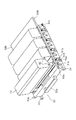
(それぞれの引き出しからの現像ユニットおよびプロセスカートリッジの着脱)
図5及び図6、図9に示すように、現像ユニット41の引き出し部材50が引き出し位置に位置する状態で、現像ユニット41(41y、41m、41c、41k)は、実質的に重力方向に沿って引き出し部材50へユーザにより着脱される。この際、現像ユニット41(41y、41m、41c、41k)は露光装置3(3y、3m、3c、3k)の上方向を覆うよう配置され現像ユニット41のトナー収容部と露光装置3が鉛直方向で重なる。この結果引き出し部材50内のスペースおよび画像形成装置100内のスペースが十分活用されることになる。また、トナー容量も確保できる。
(Removal of development unit and process cartridge from each drawer)
As shown in FIGS. 5, 6, and 9, the developing unit 41 (41 y, 41 m, 41 c, 41 k) is substantially along the direction of gravity with the
そして、現像ユニット41は、その長手方向(現像ローラ40の軸線方向)が引き出し部材50の移動方向と直交する方向となるように、移動方向に並べて配列されている。
The developing
図7及び図8、図10に示すように、プロセスカートリッジPの引き出し部材60が引き出し位置に位置する状態で、プロセスカートリッジP(Py、Pm、Pc、Pk)は、実質的に重力方向に沿って引き出し部材60へユーザにより着脱される。プロセスカートリッジPは、引き出し部材60に対して取り外しと装着が可能になる。
As shown in FIGS. 7, 8, and 10, the process cartridge P (Py, Pm, Pc, Pk) is substantially along the direction of gravity in a state where the
そして、プロセスカートリッジPは、その長手方向(感光体ドラムの軸線方向)が引き出し部材60の移動方向と直交する方向となるように、移動方向に並べて配列されている。
The process cartridges P are arranged side by side in the movement direction such that the longitudinal direction (axial direction of the photosensitive drum) is perpendicular to the movement direction of the
(引き出し部材の装置本体への装着)
現像ユニット41(41y、41m、41c、41k)及びプロセスカートリッジP(Py、Pm、Pc、Pk)は、それぞれの引き出し部材50、60に保持された状態で、引き出し部材と共に画像形成装置100の内部へ進入する。
(Mounting the drawer member to the main unit)
The developing unit 41 (41y, 41m, 41c, 41k) and the process cartridge P (Py, Pm, Pc, Pk) are held in the
さらに、ユーザは、それぞれの引き出し部材50、60を画像形成装置100内に進入させ、ドア10を閉じることにより、各現像ユニット41及び各プロセスカートリッジPを画像形成装置100に確実に装着できる。
Further, the user can securely attach the developing
ここでドア10にはストッパー10bが設けられており、ドア10を閉じる動作に連動してストッパー10bが引き出し部材50の現像離間部材51と、引き出し部材60の感光体離間部材61をそれぞれ押圧していく。このストッパー10bの押圧により、現像離間部材51と感光体離間部材61は、収納方向D2に移動する。つまり、現像離間部材51と感光体離間部材61により、感光体ドラム1から離間されていた露光装置3および現像ユニット41と、転写ベルト11から離間されていた感光体ドラム1の離間が解除され、それぞれの位置が決められる。
Here, the
このとき、離間部材51、61が付勢部材51c、61cにより引出方向D1に付勢される力に抗いながらドア10を閉じる力が発生する。しかしドア10の回転中心10c(支点)の近くにストッパー10b(作用点)を、回転中心10cから離れた位置に把手部10a(力点)を設けることによりユーザがドア10を閉める負荷を軽減している。
At this time, a force for closing the
以上のように、本実施例によれば、現像ユニットとプロセスカートリッジを収納したそれぞれの引き出し部材を本体装置のドアの開閉に連動して上下動させる構成に比べ、本体装置の構造を簡易化することができる。また、現像ユニットとプロセスカートリッジを収納した引き出し部材を上下動させる負荷がかからないため、引き出し部材の簡素化およびユーザが本体装置のドアを開閉する負荷を軽減させることができる。 As described above, according to the present embodiment, the structure of the main unit is simplified as compared with the configuration in which the respective drawer members containing the developing unit and the process cartridge are moved up and down in conjunction with the opening and closing of the door of the main unit. be able to. Further, since the load for moving the drawer member containing the developing unit and the process cartridge up and down is not applied, simplification of the drawer member and the load for the user to open and close the door of the main body device can be reduced.
<実施例2>
以下では図12(a)、(b)、(c)に基づいて別の実施例について説明する。なお実施例1で説明した構成と同様の構成については、説明を省略する。
<Example 2>
Hereinafter, another embodiment will be described with reference to FIGS. 12 (a), (b), and (c). The description of the same configuration as that described in the first embodiment is omitted.
実施例1では、複数の現像ユニット41(41y、41m、41c、41k)と、複数の露光装置3(3y、3m、3c、3k)は、ドア10の開閉に合わせてほぼ同時に移動を開始していた。
In the first embodiment, the plurality of developing units 41 (41y, 41m, 41c, 41k) and the plurality of exposure apparatuses 3 (3y, 3m, 3c, 3k) start to move almost simultaneously with the opening and closing of the
しかしながら、複数の現像ユニット41と複数の露光装置3の移動開始タイミングが同じであれば、ドア10を開閉する際に一度に加わる力が大きくなる場合がある。その場合には、複数の現像ユニット41と複数の露光装置3の移動開始タイミングを異ならせることも考えられる。
However, if the movement start timings of the plurality of developing
その一例として、図12ではドア10が開いた際に、露光装置3(3y、3m、3c、3k)が現像ユニット41(41y、41m、41c、41k)よりも先に移動(上昇)を開始する構成を示した。つまりドア10が開いた際、現像離間部材51は同じ感光体ドラム1に作用する露光装置3と現像ユニット41の内、露光ユニット3を現像ユニット41よりも先に感光体ドラム1から離す。
As an example, in FIG. 12, when the
図12(a)はドア10が閉じている状態であり露光装置3および現像ユニット41は画像形成可能な位置(画像形成するための位置)にある。図12(b)はドア10が開く途中の状態であり、現像離間部材51が露光装置3の突起部に接触することで、露光装置3が移動(上昇)を開始し感光体ドラムから離れる。さらにドア10の開き動作を続けると、現像離間部材51が現像ユニット41の突起部42に接触することで現像ユニット41が移動(上昇)を開始し、感光体ドラムから離れる。
FIG. 12A shows a state in which the
この構成ではドア10を開く際に露光装置3にトナーが付着するのを抑制する効果がある。以下の理由によるものである。ドア10が開いた際に現像ユニット41が動くと、現像ユニット41の現像ローラが担持している現像剤(トナー)が飛散する可能性がある。しかし本実施例では、現像ユニット41が移動するより先に露光装置3が移動を開始していて、現像ユニット41の移動開始時(上昇開始時)には、露光ユニット3が現像ユニット41から離れた位置にある。現像ユニット41からトナーが飛散したとしても、そのトナーが露光装置3に付着しにくい。なお図12の構成ではドア10が閉まる際には、現像ユニット41よりも先に露光装置3が移動(降下)する。
This configuration has an effect of suppressing toner from adhering to the
なお、ドア10がしまる際に、露光装置3が現像ユニット41より先に移動する構成も考えられる。この場合はドア10が開く際には、現像ユニット41が露光装置3よりも先に動く(露光装置3が現像ユニット41より後に動く)構成となる。つまり、ドア10が開く際よりも、ドア10が閉まる際のほうが露光装置3にトナーが付着しやすい状況下であれば、ドア10が閉まる際に露光装置3を現像ユニット41より先に移動させてもよい。ドア10の開き動作で露光装置3を現像ユニット41より先に動かすべきか、あるいはドア10の閉じ動作の際に露光装置3を現像ユニット41より先に動かすべきかは、画像形成装置100の構成による。その構成に合わせていずれか適切なほうを適宜選択すればよい。
A configuration in which the
<実施例3>
なお、単にドア10の開閉に必要な力を減ずるだけでよければ、現像ユニット41y、41m、41c、41kや、露光装置3y、3m、3c、3kの移動開始タイミングを変える構成も考えられる。その一例を、図13を用いて説明する。
<Example 3>
If it is sufficient to reduce the force required to open and close the
ドア10を開く過程において、先ず図13(a)に示すように、現像ユニット41y、41m、露光装置3y、3mが先に上昇移動する。そのあとで図13(b)に示すように、プロセスカートリッジPy、Pmと現像ユニット41c、41k、露光装置3c、3kが移動する。そのあと図13(c)に示すようにプロセスカートリッジPc、Pkが上昇移動する。
In the process of opening the
なお本実施例では、プロセスカートリッジPy、Pm、Pc、Pkの移動開始タイミングも異ならせることでドア10の開閉に加わる力をさらに低減している。
In this embodiment, the force applied to the opening and closing of the
<実施例4>
本実施例について図14に基づいて説明する。上述の実施例では、ドア10の開閉によって、現像離間部材51が現像ユニット41や露光装置3を動かす構成であった。しかし本実施例では、引き出し部材50に設けた把持部50aをユーザが握ると、把持部50aに設けたレバー50a1が移動し、現像離間部材51が移動する構成である。すなわち現像離間部材51を動かす(操作する)操作部がドア10ではなく把持部50aとなっている。
<Example 4>
This embodiment will be described with reference to FIG. In the above-described embodiment, the developing
図14に示すようにレバー50a1は現像離間部材51と連結している。把持部51aをユーザが握っていない状態が図14(a)であり、把持部51aをユーザが握っている状態が図14(b)である。
As shown in FIG. 14, the
図14(a)、(b)を比較するとわかるように、レバー50a1が引き出し部材50に対して移動することによって、現像離間部材51も移動し、これにより現像離間部材51は現像ユニット41や露光装置3を動かす。図14(b)は、ユーザが、把持部51aを握ることで、現像ユニット4や露光装置3がプロセスカートリッジPから離れる方向に移動した状態を表している。
14A and 14B, when the lever 50a1 moves with respect to the pull-out
つまり、引き出し部材50が画像形成装置の内部にある状態でユーザが把持部51aを握れば、現像ユニット4や露光装置3がプロセスカートリッジPの感光体ドラム1から離れた状態になる。この状態で引き出し50を画像形成装置の内部から外部に移動させることができる。一方、引き出し部材50が画像形成装置の内部に位置した状態でユーザが把持部51aを離して、把持部51aが把持された状態が解消されると現像ユニット4や露光装置3がプロセスカートリッジPの感光体ドラムに近づく。この状態で現像ユニット4や露光装置3は画像形成可能な状態になる。
That is, when the user holds the
図15では引き出し60の構成を示している。引き出し部材60に設けた把持部60aをユーザが握ると、把持部60aに設けたレバー60a1が移動し、感光体離間部材61が移動する構成である。すなわち感光体離間部材61を動かす操作部がドア10ではなく把持部60aとなっている。
FIG. 15 shows the configuration of the
図15に示すようにレバー60a1は感光体離間部材61と連結している。把持部61aをユーザが握っていない状態が図15(a)であり、把持部61aをユーザが握っている状態が図15(b)である。
As shown in FIG. 15, the
図15(a)、(b)を比較するとわかるように、レバー60a1が引き出し部材60に対して移動することによって、感光体離間部材61も移動し、これにより感光体離間部材61はプロセスカートリッジPを動かす。図15(b)は、ユーザが、把持部61aを握ることで、プロセスカートリッジPがベルトから離れる方向に移動した状態を表している。
15A and 15B, when the lever 60a1 moves with respect to the pull-out
つまり、引き出し部材60が画像形成装置の内部にある状態でユーザが把持部61aを握れば、プロセスカートリッジPがベルトから離れた状態になるので、引き出し60を移動させることができる。一方、引き出し部材60が画像形成装置の内部に位置する状態でユーザが把持部61aを離し把持状態が解消されると、プロセスカートリッジPがベルトに近づき感光体ドラム1に接触するので、画像形成可能な状態となる。
That is, if the user holds the
なお実施例2に示した構成に本実施例の把持部51aや把持部61aを採用してもよい。
In addition, you may employ | adopt the holding
(その他の変形例)
前述した各実施の形態では、現像ユニットとプロセスカートリッジがそれぞれの引き出し部材により装置本体から引き出される場合を例示したが、本発明はこれに限るものではない。例えば、プロセスカートリッジが装置本体の一部で構成される場合や、引き出し部材を使用せず交換可能に構成された場合でも、本発明を用いた現像ユニットの引き出し部材であればよい。同様に、現像ユニットが装置本体の一部で構成される場合や、引き出し部材を使用せず交換可能に構成された場合でも、本発明を用いたプロセスカートリッジの引き出し部材であればよい。
(Other variations)
In each of the above-described embodiments, the case where the developing unit and the process cartridge are pulled out from the apparatus main body by the respective drawing members has been illustrated, but the present invention is not limited to this. For example, even when the process cartridge is constituted by a part of the apparatus main body, or when the process cartridge is configured to be replaceable without using the drawer member, the drawer member of the developing unit using the present invention may be used. Similarly, even when the developing unit is constituted by a part of the apparatus main body, or when the developing unit is configured to be replaceable without using a drawer member, it may be a process cartridge drawer member using the present invention.
前述した実施の形態では、トナーを収容したトナーカートリッジと現像ローラ等を収容する現像装置とが一体に構成された現像ユニットを例示したが、本発明はこれに限るものではない。例えば、トナーカートリッジと現像装置が別部品として構成される場合には、前述した実施例の現像ユニットをトナーカートリッジとして、プロセスカートリッジを現像装置と一体化して構成したものであってもよい。 In the above-described embodiment, the developing unit in which the toner cartridge that stores the toner and the developing device that stores the developing roller and the like are integrally formed is illustrated, but the present invention is not limited to this. For example, when the toner cartridge and the developing device are configured as separate parts, the developing unit of the above-described embodiment may be configured as a toner cartridge, and the process cartridge may be integrated with the developing device.
前述した実施の形態では、露光装置が現像ユニットの引き出しに一体的に設けた場合を例示したが、本発明はこれに限るものではない。例えば、露光装置が装置本体の一部で構成される場合でも、本発明を用いた現像ユニットの引き出し部材またはプロセスカートリッジの引き出し部材であればよい。 In the above-described embodiment, the case where the exposure apparatus is provided integrally with the drawer of the developing unit is exemplified, but the present invention is not limited to this. For example, even when the exposure apparatus is constituted by a part of the apparatus main body, it may be a developing unit drawer member or a process cartridge drawer member using the present invention.
また、上述した実施形態では、ベルト部材として、記録媒体Sを搬送する転写ベルト11を用いたが、転写ベルト11が中間転写ベルト(ITB)であってもよい。すなわち転写ベルト11上に直接、感光体ドラム1からトナー像を転写し、さらに転写ベルト11から記録媒体Sにトナー像を転写する構成であってもよい。
In the above-described embodiment, the
P プロセスカートリッジ(像担持体ユニット)
1 感光体ドラム(像担持体)
3 露光装置(露光ユニット)
10 ドア(開閉部材)
11 転写ベルト(ベルト部材)
41 現像ユニット
50 引き出し部材(現像ユニット支持部材)
51 現像離間部材(露光ユニット作用部材、現像ユニット作用部材)
60 引き出し部材(像担持体ユニット支持部材)
61 感光体離間部材(像担持体ユニット作用部材)
100 電子写真画像形成装置(画像形成装置)
P Process cartridge (image carrier unit)
1 Photosensitive drum (image carrier)
3 Exposure equipment (exposure unit)
10 Door (opening / closing member)
11 Transfer belt (belt member)
41 Developing
51 Development separation member (exposure unit action member, development unit action member)
60 Drawer member (image carrier unit support member)
61 Photosensitive member separation member (image carrier unit acting member)
100 Electrophotographic image forming apparatus (image forming apparatus)
Claims (19)
像担持体を有する像担持体ユニットを取り外し可能に複数支持した状態で、前記画像形成装置の内部と外部との間を移動可能な像担持体ユニット支持部材と、
像担持体ユニット支持部材から独立して移動可能な現像ユニット支持部材であって、対応する像担持体に形成された静電潜像を現像するための現像ユニットを取り外し可能に複数支持した状態で、前記画像形成装置の内部と外部の間を移動可能な現像ユニット支持部材と、
それぞれ対応する像担持体を露光することで前記像担持体に静電潜像を形成する、前記現像ユニット支持部材に移動可能に支持された複数の露光ユニットと、
前記現像ユニット支持部材が前記画像形成装置の内部にある際に、前記露光ユニットを前記現像ユニット支持部材に対して移動させ、画像形成するための位置よりも対応する前記像担持体から離す露光ユニット作用部材と、
前記画像形成装置は、前記現像ユニット支持部材が前記画像形成装置の内部にある際に、前記現像ユニットを前記現像ユニット支持部材に対して移動させ、画像形成するための位置よりも対応する像担持体から離す現像ユニット作用部材と、
を有することを特徴とする画像形成装置。 In an image forming apparatus for forming an image on a recording medium,
An image carrier unit support member movable between the inside and the outside of the image forming apparatus in a state where a plurality of image carrier units having an image carrier are detachably supported;
A developing unit supporting member that is movable independently of the image carrier unit supporting member, and in a state in which a plurality of developing units for developing the electrostatic latent image formed on the corresponding image carrier are removably supported. A developing unit support member movable between the inside and the outside of the image forming apparatus;
A plurality of exposure units movably supported by the developing unit support member, each of which forms an electrostatic latent image on the image carrier by exposing a corresponding image carrier;
When the developing unit support member is inside the image forming apparatus, the exposure unit is moved with respect to the developing unit support member and separated from the corresponding image carrier rather than the position for image formation. A working member;
The image forming apparatus moves the developing unit with respect to the developing unit supporting member when the developing unit supporting member is inside the image forming apparatus, and corresponds to an image carrier corresponding to a position for image formation. A developing unit working member separated from the body;
An image forming apparatus comprising:
像担持体を有する像担持体ユニットを取り外し可能に複数支持した状態で、前記画像形成装置の内部と外部との間を移動可能な像担持体ユニット支持部材と、
像担持体ユニット支持部材から独立して移動可能な現像ユニット支持部材であって、対応する像担持体に形成された静電潜像を現像するための現像ユニットを取り外し可能に複数支持した状態で、前記画像形成装置の内部と外部の間を移動可能な現像ユニット支持部材と、
それぞれ対応する像担持体を露光することで前記像担持体に静電潜像を形成する、前記現像ユニット支持部材に移動可能に支持された複数の露光ユニットと、
前記現像ユニット支持部材が前記画像形成装置の内部にある際に、前記露光ユニットを前記現像ユニット支持部材に対して移動させ、画像形成するための位置よりも対応する前記像担持体から離す露光ユニット作用部材と、を有し、
前記露光ユニット作用部材は、複数の露光ユニットの少なくとも一つを他の露光ユニットとは移動開始のタイミングを異ならせることを特徴とする画像形成装置。 In an image forming apparatus for forming an image on a recording medium,
An image carrier unit support member movable between the inside and the outside of the image forming apparatus in a state where a plurality of image carrier units having an image carrier are detachably supported;
A developing unit supporting member that is movable independently of the image carrier unit supporting member, and in a state in which a plurality of developing units for developing the electrostatic latent image formed on the corresponding image carrier are removably supported. A developing unit support member movable between the inside and the outside of the image forming apparatus;
A plurality of exposure units movably supported by the developing unit support member, each of which forms an electrostatic latent image on the image carrier by exposing a corresponding image carrier;
When the developing unit support member is inside the image forming apparatus, the exposure unit is moved with respect to the developing unit support member and separated from the corresponding image carrier rather than the position for image formation. An action member,
The exposure unit acting member is images forming device you characterized in that the at least one other exposure units of the plurality of exposure units to vary the timing of the start moving.
前記露光ユニット作用部材は、前記開閉部材が開く動作によって前記露光ユニットを対応する像担持体から離れる方向に移動させ、前記開閉部材が閉じる動作によって前記露光ユニットを対応する像担持体に近づける方向へ移動させることを特徴とする請求項1乃至10のいずれか1項に記載の画像形成装置。 The image forming apparatus includes an opening / closing member that opens and closes an opening through which the developing unit support member passes,
The exposure unit action member moves the exposure unit in a direction away from the corresponding image carrier by the opening operation of the opening / closing member, and moves the exposure unit closer to the corresponding image carrier by the operation of closing the opening / closing member. the image forming apparatus according to any one of claims 1 to 10, characterized in that moved.
前記露光ユニット作用部材は、前記第1の把持部が把持されることで前記露光ユニットを対応する像担持体から離れる方向に移動させ、前記第1の把持部が把持された状態が解消されることで前記露光ユニットを対応する像担持体に近づける方向へ移動させることを特徴とする請求項1乃至10のいずれか1項に記載の画像形成装置。 The development unit support member includes a first grip portion that is gripped when the development unit support member moves,
The exposure unit action member moves the exposure unit in a direction away from the corresponding image carrier when the first gripping portion is gripped, and the state where the first gripping portion is gripped is resolved. the image forming apparatus according to any one of claims 1 to 10, characterized in that moving the exposure unit in a direction closer to the corresponding image bearing member by.
前記像担持体ユニット支持部材が前記画像形成装置の内部にある際に、前記像担持体ユニットを前記像担持体ユニット支持部材に対して移動させ、前記像担持体ユニットを画像形成するための位置よりも前記ベルト部材から離す像担持体ユニット作用部材と、
を有することを特徴とする請求項1乃至12のいずれか1項に記載の画像形成装置。 A belt member facing the plurality of image carriers,
When the image carrier unit support member is inside the image forming apparatus, the image carrier unit is moved with respect to the image carrier unit support member to position the image carrier unit to form an image. An image carrier unit acting member that is further away from the belt member,
The image forming apparatus according to any one of claims 1 to 12, characterized in that it has a.
前記像担持体ユニット作用部材は、前記開閉部材が開く動作によって前記像担持体ユニットをベルト部材から離れる方向に移動させ、前記開閉部材が閉じる動作によって前記像担持体ユニットをベルト部材に近づける方向へ移動させることを特徴とする請求項13乃至16のいずれか1項に記載の画像形成装置。 The image forming apparatus includes an opening / closing member that opens and closes an opening through which the image carrier unit support member passes,
The image carrier unit operating member moves the image carrier unit away from the belt member by the opening operation of the opening / closing member, and moves the image carrier unit closer to the belt member by the operation of closing the opening / closing member. the image forming apparatus according to any one of claims 13 to 16, characterized in that moved.
前記像担持体ユニット作用部材は、前記第2の把持部が把持されることで前記像担持体ユニットを前記ベルト部材から離れる方向に移動させ、前記第2の把持部が把持された状態が解消されることで前記像担持体ユニットを前記ベルト部材に近づける方向へ移動させることを特徴とする請求項13乃至16のいずれか1項に記載の画像形成装置。 The image carrier unit support member includes a second gripper that is gripped when the image carrier unit support member moves,
The image carrier unit operating member moves the image carrier unit in a direction away from the belt member when the second gripping portion is gripped, and the state where the second gripping portion is gripped is eliminated. the image forming apparatus according to the image carrier unit in any one of claims 13 to 16, wherein the moving in the direction closer to the belt member at which it is.
Priority Applications (4)
| Application Number | Priority Date | Filing Date | Title |
|---|---|---|---|
| JP2014127490A JP6386806B2 (en) | 2014-06-20 | 2014-06-20 | Image forming apparatus and developing unit |
| US14/743,165 US9304484B2 (en) | 2014-06-20 | 2015-06-18 | Image forming apparatus with moving light exposure units |
| US15/060,374 US10095178B2 (en) | 2014-06-20 | 2016-03-03 | Image forming apparatus |
| US16/123,529 US10564594B2 (en) | 2014-06-20 | 2018-09-06 | Image forming apparatus |
Applications Claiming Priority (1)
| Application Number | Priority Date | Filing Date | Title |
|---|---|---|---|
| JP2014127490A JP6386806B2 (en) | 2014-06-20 | 2014-06-20 | Image forming apparatus and developing unit |
Publications (3)
| Publication Number | Publication Date |
|---|---|
| JP2016008977A JP2016008977A (en) | 2016-01-18 |
| JP2016008977A5 JP2016008977A5 (en) | 2017-08-03 |
| JP6386806B2 true JP6386806B2 (en) | 2018-09-05 |
Family
ID=54869544
Family Applications (1)
| Application Number | Title | Priority Date | Filing Date |
|---|---|---|---|
| JP2014127490A Active JP6386806B2 (en) | 2014-06-20 | 2014-06-20 | Image forming apparatus and developing unit |
Country Status (2)
| Country | Link |
|---|---|
| US (3) | US9304484B2 (en) |
| JP (1) | JP6386806B2 (en) |
Families Citing this family (15)
| Publication number | Priority date | Publication date | Assignee | Title |
|---|---|---|---|---|
| JP6386806B2 (en) * | 2014-06-20 | 2018-09-05 | キヤノン株式会社 | Image forming apparatus and developing unit |
| JP6833362B2 (en) * | 2015-08-31 | 2021-02-24 | キヤノン株式会社 | Image forming device |
| JP6400167B2 (en) * | 2016-10-07 | 2018-10-03 | キヤノン株式会社 | Image forming apparatus |
| JP7000730B2 (en) | 2017-08-01 | 2022-01-19 | ブラザー工業株式会社 | Drum unit and image forming device |
| JP7091721B2 (en) * | 2018-03-06 | 2022-06-28 | ブラザー工業株式会社 | Image forming device |
| US10831147B2 (en) * | 2018-03-06 | 2020-11-10 | Brother Kogyo Kabushiki Kaisha | Image-forming apparatus including drum unit and support member for supporting developing cartridges and exposure heads |
| JP7017099B2 (en) * | 2018-03-06 | 2022-02-08 | ブラザー工業株式会社 | Image forming device |
| JP2020046513A (en) | 2018-09-18 | 2020-03-26 | ブラザー工業株式会社 | Image forming apparatus |
| JP2020046644A (en) * | 2018-09-21 | 2020-03-26 | ブラザー工業株式会社 | Image forming apparatus |
| US10983475B2 (en) * | 2019-02-25 | 2021-04-20 | Canon Kabushiki Kaisha | Image forming apparatus and image forming unit |
| KR20210004739A (en) * | 2019-07-05 | 2021-01-13 | 휴렛-팩커드 디벨롭먼트 컴퍼니, 엘.피. | Install toner catridge using holder |
| US11204566B2 (en) | 2019-07-17 | 2021-12-21 | Canon Kabushiki Kaisha | Image forming apparatus and developing cartridge |
| US11204575B2 (en) | 2019-07-29 | 2021-12-21 | Canon Kabushiki Kaisha | Image forming apparatus |
| JP7276014B2 (en) * | 2019-09-02 | 2023-05-18 | ブラザー工業株式会社 | image forming device |
| JP7409166B2 (en) * | 2020-03-09 | 2024-01-09 | ブラザー工業株式会社 | Image forming device |
Family Cites Families (28)
| Publication number | Priority date | Publication date | Assignee | Title |
|---|---|---|---|---|
| EP1331525A3 (en) * | 2002-01-25 | 2004-06-23 | Ricoh Company, Ltd. | Image forming apparatus with improved image quality and maintenance workability |
| JP2004163826A (en) * | 2002-11-15 | 2004-06-10 | Ricoh Co Ltd | Unit support device and image forming apparatus |
| JP4710476B2 (en) * | 2004-10-28 | 2011-06-29 | ブラザー工業株式会社 | Image forming apparatus |
| JP4134984B2 (en) * | 2004-12-27 | 2008-08-20 | ブラザー工業株式会社 | Image forming apparatus |
| JP5029388B2 (en) * | 2008-01-24 | 2012-09-19 | ブラザー工業株式会社 | Image forming apparatus |
| US8150294B2 (en) * | 2008-04-25 | 2012-04-03 | Brother Kogyo Kabushiki Kaisha | Image forming apparatus having moving mechanism for moving exposure member relative to photoconductor |
| JP4623148B2 (en) * | 2008-06-24 | 2011-02-02 | ブラザー工業株式会社 | Image forming apparatus |
| US8274540B2 (en) * | 2008-08-26 | 2012-09-25 | Brother Kogyo Kabushiki Kaisha | Image forming apparatus including positioning member for exposure unit |
| JP2010078654A (en) * | 2008-09-24 | 2010-04-08 | Canon Inc | Image forming apparatus |
| JP2010102006A (en) * | 2008-10-22 | 2010-05-06 | Canon Inc | Image forming apparatus |
| JP4565666B2 (en) * | 2009-03-19 | 2010-10-20 | キヤノン株式会社 | Color electrophotographic image forming apparatus |
| JP5440006B2 (en) * | 2009-07-29 | 2014-03-12 | 株式会社リコー | Fixing apparatus and image forming apparatus |
| JP4831790B2 (en) * | 2009-07-31 | 2011-12-07 | キヤノン株式会社 | Color electrophotographic image forming apparatus |
| JP5761948B2 (en) * | 2010-09-14 | 2015-08-12 | キヤノン株式会社 | Electrophotographic image forming apparatus |
| KR20120064766A (en) * | 2010-12-10 | 2012-06-20 | 삼성전자주식회사 | Image forming apparatus |
| JP5350455B2 (en) * | 2010-12-16 | 2013-11-27 | キヤノン株式会社 | Electrophotographic image forming apparatus |
| US8583004B2 (en) * | 2010-12-27 | 2013-11-12 | Brother Kogyo Kabushiki Kaisha | Image forming apparatus having exposure unit moving mechanism |
| JP5212490B2 (en) * | 2011-01-14 | 2013-06-19 | ブラザー工業株式会社 | Image forming apparatus |
| JP5533683B2 (en) * | 2011-01-14 | 2014-06-25 | ブラザー工業株式会社 | Image forming apparatus |
| JP5282791B2 (en) * | 2011-01-14 | 2013-09-04 | ブラザー工業株式会社 | Image forming apparatus |
| JP5304805B2 (en) * | 2011-01-14 | 2013-10-02 | ブラザー工業株式会社 | Image forming apparatus |
| JP5206817B2 (en) * | 2011-02-10 | 2013-06-12 | ブラザー工業株式会社 | Image forming apparatus |
| JP5768530B2 (en) * | 2011-06-27 | 2015-08-26 | ブラザー工業株式会社 | Image forming apparatus |
| JP5929174B2 (en) * | 2011-12-26 | 2016-06-01 | ブラザー工業株式会社 | Image forming apparatus |
| JP2013182004A (en) * | 2012-02-29 | 2013-09-12 | Brother Ind Ltd | Image forming apparatus |
| JP5910359B2 (en) * | 2012-07-03 | 2016-04-27 | ブラザー工業株式会社 | Image forming apparatus |
| JP6083175B2 (en) * | 2012-09-27 | 2017-02-22 | ブラザー工業株式会社 | Image forming apparatus |
| JP6386806B2 (en) * | 2014-06-20 | 2018-09-05 | キヤノン株式会社 | Image forming apparatus and developing unit |
-
2014
- 2014-06-20 JP JP2014127490A patent/JP6386806B2/en active Active
-
2015
- 2015-06-18 US US14/743,165 patent/US9304484B2/en active Active
-
2016
- 2016-03-03 US US15/060,374 patent/US10095178B2/en active Active
-
2018
- 2018-09-06 US US16/123,529 patent/US10564594B2/en active Active
Also Published As
| Publication number | Publication date |
|---|---|
| US10095178B2 (en) | 2018-10-09 |
| US20190004471A1 (en) | 2019-01-03 |
| US9304484B2 (en) | 2016-04-05 |
| US20150370219A1 (en) | 2015-12-24 |
| US20160187842A1 (en) | 2016-06-30 |
| JP2016008977A (en) | 2016-01-18 |
| US10564594B2 (en) | 2020-02-18 |
Similar Documents
| Publication | Publication Date | Title |
|---|---|---|
| JP6386806B2 (en) | Image forming apparatus and developing unit | |
| US8095039B2 (en) | Image forming apparatus with an opening and closing unit | |
| JP4979792B2 (en) | Electrophotographic image forming apparatus | |
| JP5838611B2 (en) | Image forming apparatus | |
| JP5838609B2 (en) | Image forming apparatus | |
| JP5839823B2 (en) | Image forming apparatus | |
| KR101848397B1 (en) | Image forming apparatus | |
| CN103777504A (en) | Image forming apparatus | |
| JP5896963B2 (en) | Image forming apparatus and process cartridge | |
| JP5241138B2 (en) | Electrophotographic image forming apparatus | |
| JP2018097285A (en) | Process cartridge and image formation apparatus | |
| KR20040003379A (en) | OPC unit exchanging apparatus | |
| JP4991951B2 (en) | Color electrophotographic image forming apparatus | |
| JP6223200B2 (en) | Photosensitive cartridge and image forming apparatus | |
| JP6083175B2 (en) | Image forming apparatus | |
| JP2006268064A (en) | Image forming apparatus | |
| JP5750923B2 (en) | Image forming apparatus | |
| JP5782901B2 (en) | Image forming apparatus | |
| US20100215398A1 (en) | Image forming apparatus, image forming structure, and developer recovery container | |
| JP5776183B2 (en) | Image forming apparatus | |
| JP2006343781A (en) | Image forming apparatus | |
| JP5158308B2 (en) | Image forming apparatus | |
| JP2013127653A (en) | Electrophotographic image forming apparatus | |
| JP2011191459A (en) | Detachable unit and image forming apparatus with the same | |
| JP5966670B2 (en) | Image forming apparatus |
Legal Events
| Date | Code | Title | Description |
|---|---|---|---|
| A521 | Request for written amendment filed |
Free format text: JAPANESE INTERMEDIATE CODE: A523 Effective date: 20170620 |
|
| A621 | Written request for application examination |
Free format text: JAPANESE INTERMEDIATE CODE: A621 Effective date: 20170620 |
|
| A977 | Report on retrieval |
Free format text: JAPANESE INTERMEDIATE CODE: A971007 Effective date: 20180131 |
|
| A131 | Notification of reasons for refusal |
Free format text: JAPANESE INTERMEDIATE CODE: A131 Effective date: 20180206 |
|
| A521 | Request for written amendment filed |
Free format text: JAPANESE INTERMEDIATE CODE: A523 Effective date: 20180405 |
|
| TRDD | Decision of grant or rejection written | ||
| A01 | Written decision to grant a patent or to grant a registration (utility model) |
Free format text: JAPANESE INTERMEDIATE CODE: A01 Effective date: 20180717 |
|
| A61 | First payment of annual fees (during grant procedure) |
Free format text: JAPANESE INTERMEDIATE CODE: A61 Effective date: 20180810 |
|
| R151 | Written notification of patent or utility model registration |
Ref document number: 6386806 Country of ref document: JP Free format text: JAPANESE INTERMEDIATE CODE: R151 |