JP6385406B2 - Image processing apparatus, image processing method, and program - Google Patents
Image processing apparatus, image processing method, and program Download PDFInfo
- Publication number
- JP6385406B2 JP6385406B2 JP2016184459A JP2016184459A JP6385406B2 JP 6385406 B2 JP6385406 B2 JP 6385406B2 JP 2016184459 A JP2016184459 A JP 2016184459A JP 2016184459 A JP2016184459 A JP 2016184459A JP 6385406 B2 JP6385406 B2 JP 6385406B2
- Authority
- JP
- Japan
- Prior art keywords
- decompression
- image
- rendering
- compressed
- band
- Prior art date
- Legal status (The legal status is an assumption and is not a legal conclusion. Google has not performed a legal analysis and makes no representation as to the accuracy of the status listed.)
- Active
Links
Images


Classifications
-
- G—PHYSICS
- G06—COMPUTING; CALCULATING OR COUNTING
- G06K—GRAPHICAL DATA READING; PRESENTATION OF DATA; RECORD CARRIERS; HANDLING RECORD CARRIERS
- G06K15/00—Arrangements for producing a permanent visual presentation of the output data, e.g. computer output printers
- G06K15/02—Arrangements for producing a permanent visual presentation of the output data, e.g. computer output printers using printers
- G06K15/18—Conditioning data for presenting it to the physical printing elements
- G06K15/1848—Generation of the printable image
- G06K15/1856—Generation of the printable image characterized by its workflow
- G06K15/1857—Generation of the printable image characterized by its workflow involving parallel processing in the same printing apparatus
-
- G—PHYSICS
- G06—COMPUTING; CALCULATING OR COUNTING
- G06K—GRAPHICAL DATA READING; PRESENTATION OF DATA; RECORD CARRIERS; HANDLING RECORD CARRIERS
- G06K15/00—Arrangements for producing a permanent visual presentation of the output data, e.g. computer output printers
- G06K15/02—Arrangements for producing a permanent visual presentation of the output data, e.g. computer output printers using printers
- G06K15/18—Conditioning data for presenting it to the physical printing elements
- G06K15/1801—Input data handling means
- G06K15/181—Receiving print data characterized by its formatting, e.g. particular page description languages
- G06K15/1811—Receiving print data characterized by its formatting, e.g. particular page description languages including high level document description only
- G06K15/1813—Page description language recognition
-
- G—PHYSICS
- G06—COMPUTING; CALCULATING OR COUNTING
- G06K—GRAPHICAL DATA READING; PRESENTATION OF DATA; RECORD CARRIERS; HANDLING RECORD CARRIERS
- G06K15/00—Arrangements for producing a permanent visual presentation of the output data, e.g. computer output printers
- G06K15/02—Arrangements for producing a permanent visual presentation of the output data, e.g. computer output printers using printers
- G06K15/18—Conditioning data for presenting it to the physical printing elements
- G06K15/1801—Input data handling means
- G06K15/1817—Buffers
-
- G—PHYSICS
- G06—COMPUTING; CALCULATING OR COUNTING
- G06K—GRAPHICAL DATA READING; PRESENTATION OF DATA; RECORD CARRIERS; HANDLING RECORD CARRIERS
- G06K15/00—Arrangements for producing a permanent visual presentation of the output data, e.g. computer output printers
- G06K15/02—Arrangements for producing a permanent visual presentation of the output data, e.g. computer output printers using printers
- G06K15/18—Conditioning data for presenting it to the physical printing elements
- G06K15/1835—Transforming generic data
- G06K15/1836—Rasterization
- G06K15/184—Rasterization from compressed bitmap data
-
- G—PHYSICS
- G06—COMPUTING; CALCULATING OR COUNTING
- G06K—GRAPHICAL DATA READING; PRESENTATION OF DATA; RECORD CARRIERS; HANDLING RECORD CARRIERS
- G06K15/00—Arrangements for producing a permanent visual presentation of the output data, e.g. computer output printers
- G06K15/02—Arrangements for producing a permanent visual presentation of the output data, e.g. computer output printers using printers
- G06K15/18—Conditioning data for presenting it to the physical printing elements
- G06K15/1848—Generation of the printable image
- G06K15/1849—Generation of the printable image using an intermediate representation, e.g. a list of graphical primitives
- G06K15/1851—Generation of the printable image using an intermediate representation, e.g. a list of graphical primitives parted in a plurality of segments per page
-
- G—PHYSICS
- G06—COMPUTING; CALCULATING OR COUNTING
- G06K—GRAPHICAL DATA READING; PRESENTATION OF DATA; RECORD CARRIERS; HANDLING RECORD CARRIERS
- G06K2215/00—Arrangements for producing a permanent visual presentation of the output data
- G06K2215/0002—Handling the output data
- G06K2215/004—Generic data transformation
- G06K2215/0042—Rasterisation
- G06K2215/0045—Converting outline to bitmap
-
- G—PHYSICS
- G06—COMPUTING; CALCULATING OR COUNTING
- G06K—GRAPHICAL DATA READING; PRESENTATION OF DATA; RECORD CARRIERS; HANDLING RECORD CARRIERS
- G06K2215/00—Arrangements for producing a permanent visual presentation of the output data
- G06K2215/0002—Handling the output data
- G06K2215/0062—Handling the output data combining generic and host data, e.g. filling a raster
- G06K2215/0065—Page or partial page composition
- G06K2215/0068—Line composition, e.g. kerning
Landscapes
- Engineering & Computer Science (AREA)
- General Engineering & Computer Science (AREA)
- Physics & Mathematics (AREA)
- General Physics & Mathematics (AREA)
- Theoretical Computer Science (AREA)
- Computational Linguistics (AREA)
- Record Information Processing For Printing (AREA)
- Storing Facsimile Image Data (AREA)
- Compression Of Band Width Or Redundancy In Fax (AREA)
Description
本発明は、印刷データのバンド並列レンダリング技術に関する。 The present invention relates to a band parallel rendering technique for print data.
従来より、レンダリングを高速化するための様々な技術が提案されている。例えば特許文献1には、MFP(Multi Function Peripheral)内に複数のレンダラを有し、1ページ分の印刷データ(PDLデータ)をページより小さな領域サイズ毎に並列してレンダリング処理する技術がある。また、レンダリング技術の1つとしてスキャンラインアルゴリズムが一般的に知られている。スキャンラインアルゴリズムとは、PDLデータから中間データを作成して一度保持し、当該中間データに従って該当する画素の色値を決定しながら、スキャンライン単位で画像を形成するアルゴリズムである。また、レンダリングに必要なメモリを削減する手法として、オブジェクト圧縮が知られている。オブジェクト圧縮は、印刷データに含まれるPDL(Page Description Language)にて定義された画像を可逆あるいは非可逆圧縮した圧縮画像を作り、RIPで出力画像を形成する際には必要に応じて圧縮画像を伸長して描画画像とする手法である。 Conventionally, various techniques for speeding up rendering have been proposed. For example, Japanese Patent Application Laid-Open No. H10-228561 has a technique that includes a plurality of renderers in an MFP (Multi Function Peripheral) and renders print data (PDL data) for one page in parallel for each region size smaller than the page. A scan line algorithm is generally known as one of rendering techniques. The scan line algorithm is an algorithm that creates intermediate data from PDL data, holds it once, and forms an image in units of scan lines while determining the color value of the corresponding pixel according to the intermediate data. Further, object compression is known as a technique for reducing the memory required for rendering. Object compression creates a compressed image that is reversibly or irreversibly compressed from an image defined in PDL (Page Description Language) included in the print data. When forming an output image with RIP, the compressed image is This is a technique for expanding the drawing image.
スキャンラインアルゴリズムとオブジェクト圧縮を併用する場合、スキャンライン上に存在する全ての描画画像を伸長しておく必要がある。圧縮画像を伸長する領域を有効活用する技術として、特許文献2が提案されている。具体的には、中間データを作る際に、ページ上部に登場する圧縮画像の伸長先バッファを、ページ下部に登場する圧縮画像の伸長先バッファとして使いまわせるよう、双方の圧縮画像に、同じ伸長バッファアドレス(メモリアドレス)を関連付けるというものである。
When the scan line algorithm and object compression are used together, it is necessary to decompress all the drawn images existing on the scan line.
上記特許文献2の技術を特許文献1のバンド並列レンダリングに適用すると、次のような場面で描画不正の問題が起こり得た。描画不正の問題が生じ得る場面は、同じアドレスに関連付けられた2つの圧縮画像が中間データに含まれ、かつ、2つの圧縮画像それぞれが隣接する2つのバンド(上バンドと下バンド)別々に必要とされるような場面である。そして、このような場面で、第1のレンダラが上バンド内にある圧縮画像の伸長結果(RAW画像)を用いたレンダリング中に、第2のレンダラが下バンド内にある圧縮画像の伸長結果を用いたレンダリングを開始したとする。そうなると、第1のレンダラが処理中のRAW画像が、第2のレンダラが処理するRAW画像によって上書きされてしまい、不正描画となるわけである。
When the technique of
本発明は、スキャンラインアルゴリズムとオブジェクト圧縮を併用したバンド並列レンダリングを行う場合において、上述した描画不正の問題を回避することを目的とする。 An object of the present invention is to avoid the above-mentioned problem of rendering fraud when performing band parallel rendering using both a scanline algorithm and object compression.
本発明に係る画像処理装置は、印刷データを変換して中間データをページ単位で生成する中間データ生成手段と、生成された中間データに基づいて、ページよりも小さいバンド単位で並列にレンダリングを行い、ビットマップ画像データを生成するレンダリング手段と、を備えた画像処理装置であって、前記中間データ生成手段は、ページ内に複数の圧縮画像によるイメージのオブジェクトが含まれ、当該複数の圧縮画像を伸長するための伸長バッファのアドレスに同じアドレスを指定する場合、当該複数の圧縮画像が属するバンドの情報に基づいて、先に伸長される圧縮画像が後に伸長される圧縮画像によって上書きされないように各圧縮画像に対して共通のアドレスを指定し、前記レンダリング手段は、担当するバンドのみのビットマップ画像データを生成する複数のレンダリング処理手段と、前記複数のレンダリング処理手段のうちいずれかのレンダリング処理手段からの伸長指示に基づいて、前記指定された共通のアドレスの伸長バッファに前記複数の圧縮画像を順次伸長する1個の伸長処理手段と、を有し、前記複数のレンダリング処理手段は、前記伸長処理手段による伸長結果を用いて、それぞれが担当するバンドのビットマップ画像データを生成することを特徴とする。 An image processing apparatus according to the present invention includes an intermediate data generating unit that converts print data and generates intermediate data in units of pages, and performs rendering in parallel in units of bands smaller than pages based on the generated intermediate data. A rendering unit that generates bitmap image data, wherein the intermediate data generation unit includes an image object by a plurality of compressed images in a page, and the plurality of compressed images When the same address is designated as the address of the decompression buffer for decompression, each of the compressed images to be decompressed first is not overwritten by the compressed image to be decompressed later based on the information of the band to which the plurality of compressed images belong. A common address is designated for the compressed image, and the rendering means is a bitmap of only the band in charge. A plurality of compression processing means for generating image data; and the plurality of compressed images in the decompression buffer at the designated common address based on a decompression instruction from any one of the plurality of rendering processing means. A plurality of rendering processing means, and the plurality of rendering processing means generate bitmap image data of bands in charge of each using the decompression result by the decompression processing means. Features.
本発明によれば、バンド並列レンダリングを行う場合において、上述した描画不正の問題を回避しつつ、メモリ領域を効率的に使いまわすことが出来る。 According to the present invention, when performing band parallel rendering, it is possible to efficiently use the memory area while avoiding the above-mentioned problem of fraudulent drawing.
以下、添付の図面を参照して、本発明を実施する形態について説明する。なお、以下の実施例において示す構成は一例に過ぎず、本発明は図示された構成に限定されるものではない。 Hereinafter, embodiments of the present invention will be described with reference to the accompanying drawings. The configurations shown in the following embodiments are merely examples, and the present invention is not limited to the illustrated configurations.
まず、本実施例に係る画像形成装置のハードウェア構成について説明する。図1は、画像形成装置のハードウェア構成の一例を示す図である。図1に示す画像形成装置100は、ホストPC130とLAN120を介して接続されている。印刷を行いたいユーザは、ホストPC130において印刷対象の文書についての印刷ジョブを生成し、ホストPC130からLAN120を介して画像形成装置100に対して送信する。印刷ジョブにはページ記述言語(Page Description Language)で記述された、文字、写真、図形といったオブジェクトをページ内にどのように配置するかを指定するデータ(PDLデータ)を含んでいる。そのため印刷ジョブは印刷データとも呼ばれる。そして、本実施例では、PDLデータのページ内に写真オブジェクトの圧縮画像を含んでいることが前提となる。なお、ここでの画像形成装置100は、中間データに対しバンド単位の並列レンダリングを行なって印刷を行うSFP(Single Function Printer)を想定している。しかし、画像形成装置はコピーやFAXといった複数の機能を備えたMFPであってもよい。中間データに対してバンド単位の並列レンダリングによって印刷を行う機能(印刷手段)を有する装置であれば、本実施例の手法は幅広く適用可能である。以下、本実施例の画像形成装置100を構成する各部について説明する。
First, the hardware configuration of the image forming apparatus according to the present embodiment will be described. FIG. 1 is a diagram illustrating an example of a hardware configuration of the image forming apparatus. An
CPU101は各種演算処理を行なうプロセッサであり、画像形成装置100全体の制御を司る。RAM102は、CPU101が動作するためのシステムワークメモリである。また、RAM102は、ホストPC130から受け取った印刷ジョブ内のPDLデータを解釈して生成される中間データを一時的に格納したり、中間データをレンダリング処理する際の作業領域でもある。ROM103は、システムのブートプログラムなどを格納する。大容量記憶部104は、例えばハードディスクドライブであり、各種処理のためのシステムソフトウェアやホストPC130から受信した印刷ジョブを格納する。
A
操作部105は、各種メニューや印刷データ情報等を表示するためのディスプレイ及びユーザが各種入力操作を行うためのボタンやキーを有し、操作部I/F106を介してシステムバス109と接続される。
The
ネットワークI/F107は、LAN120を介してホストPC130を含む外部装置との間で各種データ・情報のやり取りを行うインタフェースである。これら各部は、システムバス108に接続されている。
The network I / F 107 is an interface for exchanging various types of data and information with external devices including the host PC 130 via the
イメージバスI/F109は、システムバス108と画像データを高速に転送するイメージバス110とを接続するインタフェースであって、データ構造を変換するバスブリッジである。イメージバス110には、RIP(Raster Image Processor)111とプリンタ部112が接続されている。
An image bus I / F 109 is an interface that connects the
RIP111は、複数のプロセッサ、メモリ、伸長処理回路などで構成され、CPU101からの指示に基づき、PDLデータから生成された中間データであるDL(ディスプレイリスト)をラスタ形式の画像データ(ビットマップ画像データ)に変換する。プリンタ部112は、RIP111で生成されたビットマップ画像データをデバイスI/F113を介して受け取って、紙等の記録媒体に画像を形成して出力する。なお、本明細書において「レンダリング」とは、中間データであるDLからラスタ形式の画像データを生成することを意味し、いわゆるラスタライズと同義である。
The
図2(a)は、画像形成装置100の印刷処理に関するソフトウェア構成を示すブロック図であり、PDLデータ解析モジュール201、中間データ生成モジュール202、レンダリングモジュール203で構成される。
FIG. 2A is a block diagram illustrating a software configuration related to the printing process of the
PDLデータ解析モジュール201は、ホストPC130から入力された印刷ジョブに含まれるPDLデータを解析し、オブジェクト情報を取得する。オブジェクト情報は、さらに、属性情報、パス形状情報、オペランド情報、オペレータ情報で構成される。属性情報は、そのオブジェクトがイメージであるのか、グラフィックであるのか、テキストであるのかといったオブジェクトの属性を示す情報である。パス形状情報は、オブジェクトの描画範囲情報(Bounding Box)や、オブジェクトのアウトラインを点列で表現したパス点列情報等、オブジェクトの位置やアウトラインに関する情報である。オペランド情報は、オブジェクトのオペランド種別(例えば、ImageやFlatFill)、色情報、色空間(例えばRGB、Gray)といった、描画に関する情報である。オペレータ情報は、オブジェクトの階層(Raster Operation等)に関する情報である。取得したオブクジェト情報は、中間データ生成モジュール202に送られる。
The PDL
中間データ生成モジュール202は、PDLデータ解析モジュール201から受け取ったページ情報及びオブジェクト情報に基づいて、中間データ(DL)を生成する。DLは、ディスプレイリストの略であり、その中にはエッジリストと呼ばれるオブジェクトのエッジに関する情報が含まれる。エッジリストは、オブジェクトの開始点やアウトライン等に関するエッジ情報、エッジ同士の上下関係等に関するレベル情報、オブイジェクトの色に関するフィル情報で構成される。さらに、フィル情報には、オブジェクトが圧縮画像である場合、当該圧縮画像の格納先となるメモリ領域のアドレスを示す情報と、当該圧縮画像の伸長先となる伸長バッファのアドレスを示す情報が含まれる。中間データ生成モジュール202は、ページ内の全オブジェクトをエッジリストへ変換し、スキャンライン順に処理できるようにエッジリストをソートし、スキャンライン毎に画像形成処理する為に必要な命令(圧縮画像伸長命令、描画命令等)を発行することでDLを生成する。図3(a)は、DLのデータ構造の一例を示す図である。描画開始命令300は、そのページの描画開始を指示する命令である。圧縮画像伸長命令310は、皇族の描画命令320にて圧縮画像を描画する場合に、予めレンダラとしてのレンダリングモジュール203に対して圧縮画像の伸長を指示する命令である。この圧縮画像伸長命令310には、圧縮画像を格納するメモリ領域のアドレス情報と、その伸長先である伸長バッファのアドレス情報が含まれる。レンダリングモジュール203は、この命令を受けて、指定された伸長バッファへ圧縮画像を伸長する。描画命令320は、スキャンライン毎の描画指示命令である。描画命令320には上述したエッジ情報、レベル情報、フィル情報が含まれ、さらに圧縮画像がある場合は、その伸長先である伸長バッファのアドレス情報が含まれる。レンダリングモジュール203が描画命令を処理する時点では、圧縮画像伸長命令310の処理が完了している為、圧縮画像を伸長して得られたRAW画像が伸長バッファに格納されている。図3の(b)及び(c)は、それぞれ圧縮画像伸長命令310と描画命令320の詳細を示す図である。圧縮画像伸長命令310には、JPEG、PNG等の画像の圧縮形式、伸長前の圧縮画像のデータサイズ、圧縮画像の格納領域を特定するデータ先頭アドレス、圧縮画像の伸長先を特定する伸長先バッファアドレスの各情報が含まれる。描画命令320には、エッジの開始点を示す開始スキャンライン、エッジのアウトラインを示すパス点列、エッジ同士の上下関係等を示すレベル、フィルの種別を示すフィルタイプの各情報が含まれる。また、フィルタイプが圧縮画像である場合は、伸長後先頭アドレスの情報も含まれる。
The intermediate
レンダリングモジュール203は、生成された中間データに基づいて、バンド毎に並列でレンダリングを行い、ページ単位でビットマップ画像データを生成する。図4は、レンダリングモジュール203によるバンド毎の並列レンダリングを可能にする、本実施例に係るRIP111のハードウェア構成例を示す図である。RIP111は、第1レンダリング処理部411、第2レンダリング処理部412、及び、中間データに含まれる圧縮画像を第1レンダリング処理部411からの伸長指示に基づいて伸長する伸長処理部413で構成される。伸長処理部413で伸長された後のRAW画像データは、伸長画像格納用メモリ420に格納される。伸長画像格納メモリ420は第1レンダリング処理部411、第2レンダリング処理部412双方から参照可能であり、各々が必要とするタイミングで伸長画像格納メモリ420からRAW画像データを取得する。また、伸長処理部413は、内部にレジスタ(不図示)を有しており、受け取った伸長指示のうち伸長処理が完了した数(解凍された圧縮画像の数)を当該内部レジスタに記憶する。この内部レジスタに記憶される数値は、1ページ分の処理が終了する毎に“0”に初期化される。内部レジスタの値は、第1レンダリング処理部411、第2レンダリング処理部412双方から参照可能である。また、内部レジスタに代えて、伸長画像格納メモリ420の所定の領域に伸長処理が完了した数を格納する構成であってもよい。第1レンダリング処理部411、第2レンダリング処理部412は、DLに含まれる上述のエッジ情報とフィル情報から、各オブジェクトのビットマップ画像を生成する。
The
なお、本実施例では、PDLデータ解析モジュール201と中間データ生成モジュール202は、CPU102が所定のプログラムに従いRAM102を用いて実現する構成を想定している。しかしながら、PDLデータを解析してビットマップ画像データを生成するまでのすべての工程をRIP111内の閉じた構成の中で行うようにしてもよい。また、本実施例では前述のRAM102を伸長画像格納用メモリ420として用いることを想定しているが、RAM102とは別個に伸長画像格納のための専用メモリを設けてもよい。また、本実施例では、バンド並列レンダリングを2個のレンダリング処理部で行う構成としているが、レンダリング処理部の数は3個以上でもよい。
In this embodiment, it is assumed that the PDL
<用語の説明>
ここで、本実施例のレンダリング処理で登場する、「エッジ」「スキャンライン」「スパン」「レベル」「フィル」「バンド」の各用語について確認しておく。
<Explanation of terms>
Here, the terms “edge”, “scan line”, “span”, “level”, “fill”, and “band” that appear in the rendering processing of this embodiment will be confirmed.
エッジとは、ページ内に存在するオブジェクト同士の境界、又はオブジェクトと背景の境目を指す。すなわち、エッジはオブジェクトのアウトラインである。 An edge refers to a boundary between objects existing in a page or a boundary between an object and a background. That is, the edge is the outline of the object.
スキャンラインとは、画像形成処理において画像データが連続的にメモリ走査される主走査方向のラインである。スキャンラインの高さは1ピクセルとなっている。そして、複数のスキャンラインを束ねたものがバンドである。 A scan line is a line in the main scanning direction in which image data is continuously subjected to memory scanning in the image forming process. The height of the scan line is 1 pixel. A band is a bundle of a plurality of scan lines.
スパンとは、単一のスキャンラインにおいて、エッジ間の区間を指す。この区間のことを閉領域とも呼ぶ。 A span refers to a section between edges in a single scan line. This section is also called a closed region.
レベルとは、ページ内に描画するオブジェクト同士の上下関係を示す情報であり、各オブジェクトには必ずそれぞれ異なるレベル番号が割り振られる。レベルは、Zオーダーとも呼ばれ、ページの背面から前面に向かう方向(ページの描画範囲をXY平面で表現した際のXY平面に直交する方向:Z軸方向)に沿ったオブジェクトの並び順を表す。 The level is information indicating the vertical relationship between objects drawn on the page, and each object is always assigned a different level number. The level is also called Z order, and represents the order of objects along the direction from the back to the front of the page (the direction perpendicular to the XY plane when the drawing range of the page is expressed in the XY plane: the Z-axis direction). .
フィルとは、スパンに対する塗り情報であり、ビットマップ画像データやシェーディングのように1ピクセル毎に異なる色値を持つフィルや、ベタ塗りのようにスパン中で色値の変化がないフィルが存在する。したがって、1つのスパン(閉領域)については、当該スパンに関連するオブジェクトの数だけレベルが存在し、レベルの数だけ異なるフィルを有することになる。 Fill is paint information for a span, and there are fills having different color values for each pixel such as bitmap image data and shading, and fills in which there is no change in color value in the span such as solid paint. . Therefore, for one span (closed region), there are levels corresponding to the number of objects related to the span, and there are different fills corresponding to the number of levels.
次に、中間データ生成モジュール202の詳細について説明する。図2(b)は、中間データ生成モジュール202の内部構成を示す図である。中間データ生成モジュール202は、フィル生成モジュール211、レベル生成モジュール212、エッジ生成モジュール213、管理モジュール214の計4つのサブモジュールで構成される。
Next, details of the intermediate
フィル生成モジュール211は、オペランド情報からフィル情報を生成する。フィル生成モジュール211は、印刷対象のページ内にあるイメージオブジェクトが圧縮画像である場合、レンダリング時にその圧縮画像を伸長するための伸長バッファを確保する。なお、従来技術では全ての圧縮画像に対して別々に伸長バッファを確保していた。本実施例では、レンダリングモジュール203の並列性を担保しつつ、一部の伸長バッファを使いまわすことにより、伸長バッファの省メモリ化を実現している。伸長バッファをどのように使いまわすかについては後述する。
The
レベル生成モジュール212は、オペレータ情報からレベル情報を生成する。レベル情報は、ページ内に配置されるオブジェクトをZオーダー量(X方向およびY方向に直交するZ方向での値)で表現した情報や、オブジェクト同士の重なりに関する情報である。例えば、レベル1のオブジェクトは、レベル0のオブジェクトより上に描かれることを示す。
The
エッジ生成モジュール213は、パス形状情報からエッジ情報を生成する。また、管理モジュール214は、フィル生成モジュール211、レベル生成モジュール212及びエッジ生成モジュール213で生成した各情報をDLに登録する。
The
続いて、印刷ジョブからビットマップ画像データを生成するまでの大まかな処理の流れを説明する。図5は、印刷ジョブからビットマップ画像データが生成されるまでの流れを示すフローチャートである。この一連の処理は、ROM103に記憶されたプログラムをRAM102に展開し、これをCPU101が実行することによって実現される。以下では、図6に示す、 “A”〜“F”のイメージオブジェクトが配されたページのPDLデータを含む印刷ジョブがホストPC130から送信されたものとして説明を行なうものとする。図6中の破線は、レンダリングモジュール203の処理単位であるバンド境界を示している。本実施例では、1ページの幅が220ピクセル、高さが300ピクセルとし、1バンドが60本のスキャンラインで構成されるものとする。なお、本実施例の場合、後述するステップ507におけるレンダリング処理を並列で行なうことを目的に、予め印刷ジョブのデータを分割するようなことは行わない。
Next, a rough processing flow from generation of bitmap image data from a print job will be described. FIG. 5 is a flowchart showing a flow from generation of bitmap image data from a print job. This series of processing is realized by developing a program stored in the
ホストPC130から受信した印刷ジョブは、RAM102又は大容量記憶装置104にまず格納される。そして、ステップ501において、PDLデータ解析モジュール201は、格納された印刷ジョブに含まれるPDLデータの中から処理対象として注目するPDLコマンド(注目PDLコマンド)を読み出して解析し、前述のオブジェクト情報を取得する。
A print job received from the
ステップ502において、中間データ生成モジュール202内のフィル情報生成モジュール211は、注目PDLコマンドについて取得されたオブジェクト情報からフィル情報を生成する。フィル情報生成処理の詳細については後述する。
In
ステップ503において、レベル生成モジュール212は、オペレータ情報からレベル情報を生成する。レベル情報は、オペレータ情報に含まれるROP(Raster Operation)情報等を考慮しながら、原則としてオブジェクトの処理順にレベルが決定される。
In
ステップ504において、エッジ生成モジュール213は、パス形状情報からエッジ情報を生成する。エッジ情報は、ステップ502で生成したフィル情報(圧縮画像の格納先及び伸長先のアドレス情報を含む)とステップ503で生成したレベル情報とのリンク構造で構成される。
In
ステップ505において、管理モジュール214は、ステップ503〜ステップ504で生成した各情報をエッジリストとして、DLに登録する。
In
そして、ステップ506では、受信したPDLデータにおけるPDLコマンドの終端に達したかどうかが判定される。終端に達していなければステップ501に戻って、未処理のPDLコマンドについての処理が繰り返される。こうして、ページ単位でDLが生成される。一方、終端に達していればステップ507に進む。
In
ステップ507において、レンダリングモジュール203は、RIP111を用いて、CPU101からの指示に基づき、生成されたページ単位のDLを解析し、ビットマップ画像データを生成する。このとき、RIP111では、第1レンダリング処理部411と第2レンダリング処理部412の夫々が並列に、処理対象ページのDLにおける自身が担当するバンドについてビットマップ画像データの生成を行う。
In
以上が、印刷ジョブからビットマップ画像データを生成するまでの大まかな流れである。 The above is a general flow from generation of bitmap image data from a print job.
続いて、本実施例の特徴である伸長バッファの割り当て方法について説明する。伸長バッファの割り当ては、フィル情報生成処理においてなされる。図7は、フィル情報生成処理の詳細を示すフローチャートである。 Next, a decompression buffer allocation method that is a feature of the present embodiment will be described. The expansion buffer is assigned in the fill information generation process. FIG. 7 is a flowchart showing details of the fill information generation process.
ステップ701では、オブジェクト情報内のオペランド情報から、注目PDLコマンドに係るオブジェクトのフィルが、FlatFill(ベタ塗り)なのか或いはイメージなのかが判定される。判定の結果、フィルがFlatFillであれば、ステップ702に進んで、FlatFillで指定された色値をフィル情報として設定し、本処理を終了する。一方、フィルがイメージであれば、ステップ703に進む。
In
ステップ703では、イメージが圧縮画像であるかどうかが判定される。判定の結果、圧縮されていないRAW画像である場合は、フィル情報にそのイメージを設定して本処理を終了する。一方、圧縮画像である場合は、ステップ704へ進む。図6のページの場合、6個のオブジェクトはすべて圧縮画像であるため、ステップ704へ移行することになる。
In
ステップ704では、取得済みの伸長バッファがあるかどうかが判定される。取得済みの伸長バッファがある場合はステップ705に進み、ない場合はステップ708に進む。 In step 704, it is determined whether there is an acquired decompression buffer. If there is an acquired decompression buffer, the process proceeds to step 705; otherwise, the process proceeds to step 708.
ステップ705では、取得済みの伸長バッファのサイズと、注目PDLコマンドに係る圧縮画像を伸長した際のサイズ(以下、「注目RAWサイズ」)とが比較される。取得済みの伸長バッファが複数ある場合には、各取得済み伸長バッファのサイズと、注目RAWサイズとがそれぞれ比較される。比較の結果、取得済み伸長バッファのサイズが、注目RAWサイズと等しい或いは大きい場合はステップ706に進む。一方、注目RAWサイズの方が取得済み伸長バッファのサイズよりも大きい場合は、ステップ707に進む。
In
ステップ706では、取得済み伸長バッファに対応する圧縮画像が属するバンドと、注目PDLコマンドに係る圧縮画像(以下、注目圧縮画像)が属するバンドとが重複又は隣接しているかどうか判定される。双方の圧縮画像が属するバンドが重複又は隣接している場合は、S707へ進む。一方、双方の圧縮画像が属するバンドが重複又は隣接していない場合は、ステップ709へ進む。
In
ステップ707では、未処理の取得済み伸長バッファがあるかどうかが判定される。未処理の取得済み伸長バッファがあれば、それを次の比較対象の取得済み伸長バッファとして、注目RAWサイズとの比較が繰り返される。未処理の取得済み伸長バッファがなければ、ステップ708へ進む。
In
ステップ708では、注目圧縮画像を伸長するためのメモリ領域が注目RAWサイズ分だけ確保され、当該確保されたメモリ領域のアドレスが、当該注目圧縮画像のための伸長バッファのアドレスとして指定される。
In
ステップ709では、ステップ706で重複も隣接もしないと判定された取得済み伸長バッファのアドレスと同一のアドレスが、注目圧縮画像を伸長するための伸長バッファのアドレスとして指定される。すなわち、2つの圧縮画像について同じメモリ領域が、共通の伸長バッファとして使いまわされることになる。
In step 709, the same address as that of the acquired decompression buffer determined not to overlap or adjoin in
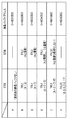
ここで、本実施例に係るフィル情報生成処理を、具体例を用いて説明する。図8は、図6に示すページにおける6個のイメージオブジェクト“A”〜“F”の画像サイズと位置関係を示すテーブルである。図8のテーブルにおいて、「圧縮サイズ」は、圧縮画像である各イメージオブジェクトのデータサイズであり、オペランド情報から得られる。「RAWサイズ」は当該圧縮画像の伸長後のデータサイズである。このRAWサイズは、伸長後の画像における幅高及び色空間(ビット数)から算出される。なお、各画像サイズの単位はKBである。「BoundingBox」は、オブジェクトの描画領域を示しており、パス形状情報から得られる。「バンド」は、BoundingBoxで特定される描画領域が属するバンドの番号を示している。例えば、オブジェクト“C”については、バンド1とバンド2の双方に跨っていることから、当該バンドの番号である1と2が記述されている。以下、説明の便宜上、各イメージオブジェクトを、“Obj_A”〜“Obj_F”で表すものとする。
Here, the fill information generation processing according to the present embodiment will be described using a specific example. FIG. 8 is a table showing the image sizes and positional relationships of the six image objects “A” to “F” on the page shown in FIG. In the table of FIG. 8, “compressed size” is the data size of each image object that is a compressed image, and is obtained from operand information. “RAW size” is the data size after decompression of the compressed image. This RAW size is calculated from the width height and color space (number of bits) in the decompressed image. The unit of each image size is KB. “BoundingBox” indicates the drawing area of the object, and is obtained from the path shape information. “Band” indicates the number of the band to which the drawing area specified by the BoundingBox belongs. For example, since the object “C” spans both
まず、先頭のObj_Aについては、先行する他のイメージオブジェクトが存在しない為(ステップ704でNo)、そのRAWサイズ=4.7KBのメモリ領域が新規に確保され、Obj_Aのための伸長バッファのアドレス(0x00010000)が指定される。 First, since there is no other preceding image object for the top Obj_A (No in step 704), a memory area of RAW size = 4.7 KB is newly secured, and the address of the decompression buffer for Obj_A (0x00010000) ) Is specified.
次に、Obj_Bについては、先行するObj_Aのための取得済み伸長バッファがあり(ステップ704でYes)、その伸長バッファサイズ(4.7KB)と、Obj_BのRAWサイズ=3.5KBとが比較される(ステップ705)。比較の結果、取得済み伸長バッファのサイズの方が大きいため(ステップ705でYes)、取得済み伸長バッファに対応するObj_Aが属するバンドと、Obj_Bが属するバンドが重複又は隣接するかが判定される(ステップ706)。この場合、いずれのバンドもバンド1なので重複することになる(ステップ706でYes)。そして、未処理の取得済み伸長バッファも存在しないため(ステップ707でNo)、Obj_BのRAWサイズ=3.5KBのメモリ領域が新たに取得され、Obj_Bのための伸長バッファのアドレス(0x00020000)が指定される(ステップ708)。
Next, for Obj_B, there is an acquired decompression buffer for the preceding Obj_A (Yes in step 704), and the decompression buffer size (4.7 KB) is compared with the RAW size of Obj_B = 3.5 KB (step) 705). As a result of comparison, since the size of the acquired decompression buffer is larger (Yes in step 705), it is determined whether the band to which Obj_A corresponding to the acquired decompression buffer belongs and the band to which Obj_B belongs overlap or are adjacent ( Step 706). In this case, since both bands are
次に、Obj_Cについては、先行するObj_A及びObj_Bについて取得済み伸長バッファがあり(ステップ704でYes)、まず、Obj_Aの伸長バッファサイズ(4.7KB)と、Obj_CのRAWサイズ=4.7KBとが比較される(ステップ705)。比較の結果、両サイズは等しいので(ステップ705でYes)、取得済みの伸長バッファに対応するObj_Aが属するバンドと、Obj_Cが属するバンドが重複又は隣接するかが判定される(ステップ706)。この場合、Obj_Cの一部もバンド1に属するので、重複することになる(ステップ706でYes)。そして、Obj_Bの取得済み伸長バッファが存在するため(ステップ707でYes)、改めてObj_Bの伸長バッファサイズ(3.5KB)と、Obj_CのRAWサイズ=4.7KBとが比較される(ステップ705)。今度は、取得済み伸長バッファのサイズの方が小さいためステップ707に進むが、未処理の取得済み伸長バッファはもう存在しないので、ステップ708に進むことになる。そして、Obj_CのRAWサイズ=4.7KBのメモリ領域が新たに確保され、Obj_Cのための伸長バッファのアドレス(0x00030000)が指定される。 Next, for Obj_C, there is an acquired decompression buffer for the preceding Obj_A and Obj_B (Yes in step 704). First, the Obj_A decompression buffer size (4.7KB) is compared with the Obj_C RAW size = 4.7KB. (Step 705). As a result of the comparison, since both sizes are equal (Yes in Step 705), it is determined whether the band to which Obj_A corresponding to the acquired decompression buffer belongs and the band to which Obj_C belongs overlap or are adjacent (Step 706). In this case, part of Obj_C also belongs to band 1 and therefore overlaps (Yes in step 706). Since there is an already acquired decompressed buffer of Obj_B (Yes in Step 707), the Obj_B decompressed buffer size (3.5 KB) is again compared with the Obj_C RAW size = 4.7 KB (Step 705). This time, since the size of the acquired decompression buffer is smaller, the process proceeds to step 707, but since there is no unprocessed acquired decompression buffer, the process proceeds to step 708. A new memory area of Obj_C RAW size = 4.7 KB is newly reserved, and an expansion buffer address (0x00030000) for Obj_C is designated.
次に、Obj_Dについては、先行するObj_A〜Obj_Cについて取得済みの伸長バッファがあり(ステップ704でYes)、まず、Obj_Aの伸長バッファサイズ(4.7KB)と、Obj_DのRAWサイズ=4.7KBとが比較される(ステップ705)。比較の結果、両サイズは等しいので、ステップ706に進む(ステップ705でYes)。取得済みの伸長バッファに対応するObj_Aが属するバンド1と、Obj_Dが属するバンド2とは隣り合っており隣接するので、ステップ707に進む(ステップ706でYes)。そして、次に、未処理のObj_Bの伸長バッファサイズ(3.5KB)と、Obj_DのRAWサイズ=4.7KBとが比較される(ステップ705)。この場合、取得済み伸長バッファのサイズの方が小さいため、ステップ707に進む(ステップ705でNo)。そして、次に、未処理のObj_Cの伸長バッファサイズ(4.7KB)と、Obj_DのRAWサイズ=4.7KBとが比較される(ステップ705)。比較の結果、両サイズは等しいので、ステップ706に進む(ステップ705でYes)。この場合、Obj_Cの一部もバンド2に属するので、重複することになる(ステップ706でYes)。再びステップ707に進むが、未処理の取得済み伸長バッファはもう存在しないので、ステップ708に進むことになる。そして、Obj_DのRAWサイズ=4.7KBのメモリ領域が新たに確保され、Obj_Dのための伸長バッファのアドレス(0x00040000)が指定される。
Next, for Obj_D, there is a decompression buffer acquired for the preceding Obj_A to Obj_C (Yes in step 704). First, the Obj_A decompression buffer size (4.7KB) is compared with the Obj_D RAW size = 4.7KB. (Step 705). As a result of comparison, since both sizes are equal, the process proceeds to step 706 (Yes in step 705). Since
次に、Obj_Eについては、先行するObj_A〜Obj_Dについて取得済みの伸長バッファがあり(ステップ704でYes)、まず、Obj_Aの伸長バッファサイズ(4.7KB)と、Obj_EのRAWサイズ=4.7KBとが比較される(ステップ705)。比較の結果、両サイズは等しいので、ステップ706に進む(ステップ705でYes)。取得済みの伸長バッファに対応するObj_Aが属するバンド1と、Obj_Eが属するバンド3とは異なるバンドであり隣り合ってもいないので、ステップ709に進む(ステップ706でNo)。その結果、Obj_Eのための伸長バッファのアドレスに、Obj_Aのための伸長バッファと同一のアドレス(0x00010000)が指定される。
Next, for Obj_E, there is a decompression buffer that has been acquired for the preceding Obj_A to Obj_D (Yes in step 704). First, Obj_A's decompression buffer size (4.7KB) is compared with Obj_E's RAW size = 4.7KB. (Step 705). As a result of comparison, since both sizes are equal, the process proceeds to step 706 (Yes in step 705). Since
最後に、Obj_Fについては、先行するObj_A〜Obj_Eについて取得済みの伸長バッファがあり(ステップ704でYes)、まず、Obj_Aの伸長バッファサイズ(4.7KB)と、Obj_FのRAWサイズ=7.0KBとが比較される(ステップ705)。比較の結果、Obj_FのRAWサイズの方が大きいため(ステップ705でNo)、ステップ707に進む。以降、残りのObj_B〜Obj_Eについて同様の処理を行うが、取得済みの伸長バッファサイズの中にObj_FのRAWサイズ以上のものはないため、ステップ708に進むことになる。そして、Obj_FのRAWサイズ=7.0KBのメモリ領域が新たに確保され、Obj_Fのための伸長バッファのアドレス(0x00050000)が指定される。 Finally, for Obj_F, there is the decompression buffer that has been acquired for the preceding Obj_A to Obj_E (Yes in step 704). First, Obj_A's decompression buffer size (4.7KB) is compared with Obj_F's RAW size = 7.0KB (Step 705). As a result of the comparison, the RAW size of Obj_F is larger (No in step 705), and the process proceeds to step 707. Thereafter, the same processing is performed for the remaining Obj_B to Obj_E, but since there is no acquired decompression buffer size larger than the RAW size of Obj_F, the process proceeds to step 708. Then, a new memory area of RAW size = 7.0 KB of Obj_F is secured, and an expansion buffer address (0x00050000) for Obj_F is designated.
以上の内容をまとめたものが、図9の表である。Obj_A〜Obj_D及びObj_Fについては新規に伸長バッファが確保されるものの、Obj_EについてはObj_Aの伸長バッファと同じアドレスが指定されており、共通のメモリ領域が使いまわされているのが分かる。 The table of FIG. 9 summarizes the above contents. Although Obj_A to Obj_D and Obj_F have newly expanded buffers, Obj_E has the same address as that of Obj_A, and a common memory area is reused.
本実施例によれば、注目圧縮画像のための伸長バッファを、当該注目圧縮画像が属するバンドとは重複も隣接もしないバンドに属する他の圧縮画像のための伸長バッファと共通にする。これにより、複数のレンダリング処理部に競合による待ち合わせを発生させることなく、伸長バッファを最大限使いまわすことが出来る。 According to this embodiment, the decompression buffer for the target compressed image is made common with the decompression buffer for other compressed images belonging to a band that does not overlap or adjoin the band to which the target compressed image belongs. As a result, the decompression buffer can be used as much as possible without causing waiting due to competition among a plurality of rendering processing units.
実施例1では、バンド並列レンダリングにおける並列性を最大限引き出しながら、使用する伸長バッファが最小で済む様な省メモリ手法について説明した。次に、バンド並列レンダリングにおける並列性を下げる代わりに、メモリ削減率を高める態様について実施例2として説明する。なお、実施例1と共通する内容については説明を省略ないしは簡略化し、以下では差異点を中心に説明するものとする。 In the first embodiment, a memory saving technique has been described in which the parallelism in the band parallel rendering is maximized while the decompression buffer to be used is minimized. Next, an embodiment in which the memory reduction rate is increased instead of reducing parallelism in band parallel rendering will be described as a second embodiment. The description common to the first embodiment will be omitted or simplified, and the following description will focus on the differences.
本実施例では、レンダリングモジュール203で伸長タイミングを制御しながら伸長メモリを使いまわすことで、メモリ削減率を実施例1の手法よりも高める。画像形成装置10のハードウェア及びソフトウェアの基本構成は実施例1と共通である。以下、本実施例の特徴であるフィル情報生成処理について、図10のフローチャートを参照して詳しく説明する。
In this embodiment, the memory reduction rate is higher than that of the first embodiment by using the expansion memory while controlling the expansion timing by the
ステップ1001〜ステップ1005は、実施例1の図7のフローチャートにおけるステップ701〜ステップ705と同様である。ステップ1005で、取得済みの伸長バッファのサイズが、注目RAWサイズと等しい或いは大きい場合はステップ1006に進む。一方、注目RAWサイズの方が取得済み伸長バッファのサイズよりも大きい場合は、ステップ1008に進む。
Steps 1001 to 1005 are the same as
ステップ1006では、取得済み伸長バッファに対応する圧縮画像と注目圧縮画像とが同一スキャンライン上に存在しないかが判定される。具体的には、それぞれの圧縮画像のBoundingBoxのY座標における最大値と最小値の値域に重複がないかを判定する。これは同一スキャンライン上に同じアドレスが指定された圧縮画像が存在すると、レンダリングモジュール203にて双方の圧縮画像についての伸長と読み込みが競合し、描画不正が生じてしまうことから、そのような事態の発生を防ぐためである。取得済み伸長バッファに対応する圧縮画像と注目圧縮画像とが同一スキャンライン上に存在しない場合は、ステップ1007に進む。一方、取得済み伸長バッファに対応する圧縮画像と注目圧縮画像とが同一スキャンライン上に存在する場合は、ステップ1008へ進む。
In step 1006, it is determined whether the compressed image corresponding to the acquired decompression buffer and the target compressed image do not exist on the same scan line. Specifically, it is determined whether there is no overlap between the maximum value and minimum value ranges in the Y coordinate of the BoundingBox of each compressed image. This is because if there is a compressed image with the same address specified on the same scan line, the
ステップ1007では、注目圧縮画像がバンド境界を跨いで存在しているかが判定される。注目圧縮画像がバンド境界を跨いでいる場合、上下それぞれのバンドを担当するレンダリング処理部が異なる。そこで、バンド毎に異なる伸長バッファを指定することで、描画不正が生じないようにする。注目圧縮画像がバンド境界を跨いでいる場合は、ステップ1008へ進む。一方、注目圧縮画像がバンド境界を跨いでいない場合は、ステップ1010へ進む。
In
ステップ1008以降は、実施例1の図7のフローチャートにおけるステップ707以降と同様である。すなわち、未処理の取得済み伸長バッファがあれば、それを次の比較対象の取得済み伸長バッファとして、注目RAWサイズとの比較が繰り返される(ステップ1008)。そして、ステップ1009では、注目圧縮画像を伸長するためのメモリ領域が注目RAWサイズ分だけ確保され、当該確保されたメモリ領域のアドレスが、当該注目圧縮画像のための伸長バッファのアドレスとして指定される。また、ステップ1010では、ステップ1005で比較を行った取得済み伸長バッファのアドレスと同一のアドレスが、注目圧縮画像を伸長するための伸長バッファのアドレスとして指定される。すなわち、同じメモリ領域が伸長バッファとして使いまわされることになる。
Steps after step 1008 are the same as those after
以下に、本実施例に係るフィル情報生成処理の具体例を、前述の図6に示すページの場合を例に説明する。 A specific example of the fill information generation process according to the present embodiment will be described below using the case of the page shown in FIG. 6 as an example.
まず、先頭のObj_Aについては、先行する他のイメージオブジェクトが存在しない為(ステップ1004でNo)、そのRAWサイズ=4.7KBのメモリ領域が新規に確保され、Obj_Aのための伸長バッファのアドレス(0x00010000)が指定される。 First, since there is no other preceding image object for the top Obj_A (No in step 1004), a new memory area of RAW size = 4.7 KB is secured, and the address of the decompression buffer for Obj_A (0x00010000) ) Is specified.
次に、Obj_Bについては、先行するObj_Aのための取得済み伸長バッファがあり(ステップ1004でYes)、その伸長バッファサイズ(4.7KB)と、Obj_BのRAWサイズ=3.5KBとが比較される(ステップ1005)。比較の結果、取得済み伸長バッファのサイズの方が大きいため(ステップ1005でYes)、取得済み伸長バッファに対応するObj_Aが同一スキャンライン上に存在しないかが判定される。ここで、Obj_AのY座標の値域は“10〜40”であり、Obj_BのY座標の値域は“20〜50”である(前述の図8のテーブルを参照)。この場合、“20〜40”で値域が重複しているため、Obj_Aが同一スキャンライン上に存在すると判定される(ステップ1006でYes)。未処理の取得済み伸長バッファは存在しないため(ステップ1008でNo)、Obj_BのRAWサイズ=3.5KBのメモリ領域が新たに確保され、Obj_Bのための伸長バッファのアドレス(0x00020000)が指定される(ステップ1009)。 Next, for Obj_B, there is an acquired decompression buffer for the preceding Obj_A (Yes in step 1004), and the decompression buffer size (4.7 KB) is compared with the raw size of Obj_B = 3.5 KB (step) 1005). As a result of the comparison, since the size of the acquired decompression buffer is larger (Yes in Step 1005), it is determined whether Obj_A corresponding to the acquired decompression buffer does not exist on the same scan line. Here, the range of the Y coordinate of Obj_A is “10 to 40”, and the range of the Y coordinate of Obj_B is “20 to 50” (see the table in FIG. 8 described above). In this case, it is determined that Obj_A exists on the same scan line because the value ranges of “20 to 40” overlap (Yes in step 1006). Since there is no unprocessed acquired decompression buffer (No in step 1008), a new memory area of Obj_B RAW size = 3.5 KB is secured, and the decompression buffer address (0x00020000) for Obj_B is designated ( Step 1009).
次に、Obj_Cについては、先行するObj_A及びObj_Bについて取得済み伸長バッファがあり(ステップ1004でYes)、まず、Obj_Aの伸長バッファサイズ(4.7KB)と、Obj_CのRAWサイズ=4.7KBとが比較される(ステップ1005)。比較の結果、両サイズは等しいので(ステップ1005でYes)、取得済み伸長バッファに対応するObj_Aが同一スキャンライン上に存在しないかが判定される。Obj_AのY座標の値域は“10〜40”であり、Obj_CのY座標の値域は“50〜80”である。この場合、値域が重複しておらず、Obj_Aが同一スキャンライン上に存在しないと判定され(ステップ1006でNo)、ステップ1007に進む。ステップ1007では、Obj_Cがバンド境界を跨いで存在しているかが判定される。Obj_Cはバンド1とバンド2の境界を跨いで存在しているため(前述の図8のテーブルを参照)、ステップ1008に進む(ステップ1007でYes)。さらに未処理の取得済み伸長バッファは存在しないため(ステップ1008でNo)、Obj_CのRAWサイズ=4.7KBのメモリ領域が新たに確保され、Obj_Cのための伸長バッファのアドレス(0x00030000)が指定される(ステップ1009)。
Next, for Obj_C, there is an acquired decompression buffer for the preceding Obj_A and Obj_B (Yes in step 1004). First, the Obj_A decompression buffer size (4.7KB) is compared with the Obj_C RAW size = 4.7KB. (Step 1005). As a result of the comparison, since both sizes are equal (Yes in step 1005), it is determined whether Obj_A corresponding to the acquired decompression buffer does not exist on the same scan line. The range of the Y coordinate of Obj_A is “10 to 40”, and the range of the Y coordinate of Obj_C is “50 to 80”. In this case, it is determined that the range does not overlap and Obj_A does not exist on the same scan line (No in step 1006), and the process proceeds to step 1007. In
次に、Obj_Dについては、先行するObj_A〜Obj_Cについて取得済みの伸長バッファがあり(ステップ1004でYes)、まず、Obj_Aの伸長バッファサイズ(4.7KB)と、Obj_DのRAWサイズ=4.7KBとが比較される(ステップ1005)。比較の結果、両サイズは等しいので(ステップ1005でYes)、取得済み伸長バッファに対応するObj_Aが同一スキャンライン上に存在しないかが判定される。Obj_AのY座標の値域は“10〜40”であり、Obj_DのY座標の値域は“70〜100”である。この場合、値域が重複しておらず、Obj_Aが同一スキャンライン上に存在しないと判定され(ステップ1006でNo)、ステップ1007に進む。ステップ1007では、Obj_Dがバンド境界を跨いで存在しているかが判定される。Obj_Dはバンド2のみに属しており(前述の図8のテーブルを参照)バンド境界を跨いでいないため(ステップ1007でYes)、ステップ1010に進む。その結果、Obj_Dのための伸長バッファのアドレスに、Obj_Aのための伸長バッファと同一のアドレス(0x00010000)が指定される。
Next, for Obj_D, there is a decompression buffer acquired for the preceding Obj_A to Obj_C (Yes in step 1004). First, Obj_A's decompression buffer size (4.7KB) is compared with Obj_D's RAW size = 4.7KB. (Step 1005). As a result of the comparison, since both sizes are equal (Yes in step 1005), it is determined whether Obj_A corresponding to the acquired decompression buffer does not exist on the same scan line. The range of the Y coordinate of Obj_A is “10 to 40”, and the range of the Y coordinate of Obj_D is “70 to 100”. In this case, it is determined that the range does not overlap and Obj_A does not exist on the same scan line (No in step 1006), and the process proceeds to step 1007. In
次に、Obj_Eについては、先行するObj_A〜Obj_Dについて取得済みの伸長バッファがあり(ステップ1004でYes)、まず、Obj_Aの伸長バッファサイズ(4.7KB)と、Obj_EのRAWサイズ=4.7KBとが比較される(ステップ1005)。比較の結果、両サイズは等しいので(ステップ1005でYes)、取得済み伸長バッファに対応するObj_Aが同一スキャンライン上に存在しないかが判定される。Obj_AのY座標の値域は“10〜40”であり、Obj_EのY座標の値域は“130〜160”である。この場合、値域が重複してしておらず、Obj_Aが同一スキャンライン上に存在しないと判定され(ステップ1006でNo)、ステップ1007に進む。ステップ1007では、Obj_Eがバンド境界を跨いで存在しているかが判定される。Obj_Eはバンド3のみに属しており(前述の図8のテーブルを参照)バンド境界を跨いでいないため(ステップ1007でYes)、ステップ1010に進む。その結果、Obj_Eのための伸長バッファのアドレスに、Obj_Aのための伸長バッファと同一のアドレス(0x00010000)が指定される。なお、この際の指定先アドレスは、Obj_Cのための伸長バッファのアドレス“0x00030000”と同一でも構わない。
Next, for Obj_E, there is a decompression buffer that has been acquired for the preceding Obj_A to Obj_D (Yes in step 1004). First, Obj_A's decompression buffer size (4.7KB) is compared with Obj_E's RAW size = 4.7KB. (Step 1005). As a result of the comparison, since both sizes are equal (Yes in step 1005), it is determined whether Obj_A corresponding to the acquired decompression buffer does not exist on the same scan line. The range of the Y coordinate of Obj_A is “10 to 40”, and the range of the Y coordinate of Obj_E is “130 to 160”. In this case, it is determined that the range does not overlap and Obj_A does not exist on the same scan line (No in step 1006), and the process proceeds to step 1007. In
最後に、Obj_Fについては、先行するObj_A〜Obj_Eについて取得済みの伸長バッファがあり(ステップ1004でYes)、まず、Obj_Aの伸長バッファサイズ(4.7KB)と、Obj_FのRAWサイズ=7.0KBとが比較される(ステップ1005)。比較の結果、Obj_FのRAWサイズの方が大きいため(ステップ1005でNo)、ステップ1008に進む。以降、残りのObj_B〜Obj_Eについて同様の処理を行うが、取得済みの伸長バッファサイズの中にObj_FのRAWサイズ以上のものはないため、ステップ1009に進むことになる。そして、Obj_FのRAWサイズ=7.0KBのメモリ領域が新たに確保され、Obj_Fのための伸長バッファのアドレス(0x00040000)が指定される。 Finally, for Obj_F, there is a decompression buffer that has been acquired for the preceding Obj_A to Obj_E (Yes in step 1004). First, Obj_A's decompression buffer size (4.7KB) is compared with Obj_F's RAW size = 7.0KB. (Step 1005). As a result of the comparison, the RAW size of Obj_F is larger (No in step 1005), and the process proceeds to step 1008. Thereafter, the same processing is performed for the remaining Obj_B to Obj_E, but since there is no acquired decompression buffer size larger than the RAW size of Obj_F, the process proceeds to step 1009. Then, a new memory area of RAW size = 7.0 KB of Obj_F is secured, and an expansion buffer address (0x00040000) for Obj_F is designated.
以上の内容をまとめたものが、図11の表である。Obj_A〜Obj_C及びObj_Fについては新規に伸長バッファが確保されるものの、Obj_DとObj_EについてはObj_Aの伸長バッファと同じアドレスが指定されており、実施例1よりもさらに共通のメモリ領域が使いまわされているのが分かる。 The table of FIG. 11 summarizes the above contents. Although Obj_A to Obj_C and Obj_F have newly expanded buffers, Obj_D and Obj_E have the same address as Obj_A's expanded buffer, and a more common memory area is used than in Example 1. I can see that
次に、本実施例に係る、バンド並列レンダリング処理について説明する。前述の通り、レンダリングモジュール203は、RIP111を用いて、CPU101からの指示に基づき、生成されたページ分のDLを解析し、ビットマップ画像データを生成する。このとき、RIP111では、第1レンダリング処理部411と第2レンダリング処理部412の夫々が並列に、生成されたページ分のDLの自身が担当する領域についてビットマップ画像データの生成を行う(前述の図5のフローチャートのステップ507)。
Next, band parallel rendering processing according to the present embodiment will be described. As described above, the
レンダリングモジュール203は、RIP111を用いて、中間データ生成モジュール202によって生成された中間データ(DL)基づき、ページ上部からスキャンライン単位のビットマップ画像データを生成していく。この際、ページを所定の領域(バンド高)毎に分け、奇数バンド領域を第1レンダリング処理部411が担当し、偶数バンド領域を第2レンダリング処理部412が担当して、ビットマップ画像データが生成される。つまり、第1レンダリング処理部411と第2レンダリング処理部412は、共通の中間データを読み込みながら並列に動作し、割り当てられた領域をレンダリングする。
The
RIP111は、DLの圧縮画像伸長命令を読み込み、上述の図10のフローで指定された伸長バッファアドレスに伸長する。この際の伸長処理は、伸長処理部413に接続する第1レンダリング処理部411からのみ行う。第2レンダリング処理部412は、第1レンダリング処理部411が伸長処理部413を用いて伸長した結果を、指定された伸長バッファアドレスを参照することで読み込む。したがって、第2レンダリング処理部412は、読み込み対象のRAW画像が所定の伸長バッファアドレスに伸長済みかどうかを確認する必要がある。また、第1レンダリング処理部411は、伸長指示を伸長処理部413に対して行う前に、所定の伸長バッファアドレスが第2レンダリング処理部412によって参照中(アクセス中)かどうかを確認する必要がある。本実施例では、上述の点を踏まえつつ、バンド並列レンダリング処理における並列性を下げる代わりにメモリの削減率を高めるものである。具体的には、レンダリングモジュール203によって、圧縮画像の伸長タイミングが以下のように制御される。
The
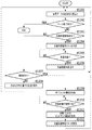
まずは、第1レンダリング処理部411が担当する第1のバンド(ここでは奇数バンド)についてのレンダリング処理について説明する。図12は、本実施例に係る、第1レンダリング処理部411におけるレンダリング処理の流れを示すフローチャートである。
First, a rendering process for the first band (in this case, an odd band) handled by the first
ステップ1201では、生成されたDLに含まれる命令を1つ読み込む。図13は、前述の図6に示すページについて生成されたDLを示している。このDL1300に含まれる命令のうちどれを読み込むのかはポインタによって管理され、先頭の命令(ここでは、描画開始命令300に相当する描画フレーム設定命令1301)から順に読み込まれる。ポインタによって指し示された命令の読み込みが完了すると、ポインタは次の命令へと移行する。こうして、DLに含まれる命令が順次読み込まれる。以下、図13で示すDL1300に基づき説明を行う。
In step 1201, one instruction included in the generated DL is read. FIG. 13 shows the DL generated for the page shown in FIG. Which of the instructions included in the
ステップ1202では、ステップ1201で読み込んだ命令がページ終了命令(描画終了命令340に相当)かどうか判定される。ここでは、読み込んだ命令がページ終了命令1313でない場合はステップ1203に進む。一方、読み込んだ命令がページ終了命令1313である場合は、本処理を終了する。
In step 1202, it is determined whether or not the instruction read in step 1201 is a page end instruction (corresponding to the drawing end instruction 340). Here, if the read instruction is not the
ステップ1203では、ステップ1201で読み込んだ命令が圧縮画像伸長命令かどうか判定される。読み込んだ命令が例えば圧縮画像伸長命令1303の場合はステップ1204に進み、それ以外の命令である場合はステップ1207に進む。
In step 1203, it is determined whether the instruction read in step 1201 is a compressed image decompression instruction. For example, if the read instruction is a compressed
ステップ1204では、読み込んだ圧縮画像伸長命令に基づき圧縮画像管理リストが作成される。図14(a)は、図13のDLにおける圧縮画像伸長命令1303及び1304の読み込みに応じて作成された圧縮画像管理リスト(以下、単に「リスト」と呼ぶ。)の一例である。リスト内の「伸長番号」は、伸長処理部413に伸長指示を行う順番を示す。「伸長後のメモリサイズ」は、圧縮画像を伸長した後のRAW画像のデータサイズを示す。「伸長先バッファアドレス」は、DLに示される伸長バッファアドレスを示す。「第1レンダリング処理部参照状態」と「第2レンダリング処理部参照状態」は、それぞれのレンダリング処理部における、伸長されたRAW画像の参照の要否を表す情報が入る。具体的には、“参照する”と“参照しない”の2状態である。この場合において“参照しない”には、対象のRAW画像が担当領域(バンド)外にある場合と、既にビットマップ画像の生成が完了しており以降の処理で当該RAW画像を参照する必要がない場合の2通りの状態が含まれる。この参照状態の情報は、“参照する”であれば“0”、“参照しない”であれば“1”といった具合に、フラグ等によって保持される。なお、初期設定は“参照する(0)”である。
In step 1204, a compressed image management list is created based on the read compressed image decompression command. FIG. 14A is an example of a compressed image management list (hereinafter simply referred to as “list”) created in response to reading of the compressed
ステップ1205では、圧縮画像管理リストの情報を元に、読み込んだ圧縮画像伸長命令が処理可能であるか否かが判定される。次に続く命令を正常に処理し描画不正の発生を未然に防ぐためである。伸長処理の実行が可能になるまで、圧縮画像管理リストの監視が継続される。この監視処理については、第2レンダリング処理部412におけるレンダリング処理の説明において、具体例を示しつつ詳しく述べることとする。
In step 1205, based on the information in the compressed image management list, it is determined whether or not the read compressed image decompression command can be processed. This is because the subsequent instruction is normally processed to prevent the occurrence of drawing fraud. The compressed image management list is continuously monitored until the decompression process can be executed. This monitoring process will be described in detail in the description of the rendering process in the second
ステップ1206では、圧縮画像を伸長画像格納メモリ420に伸長するように伸長処理部413に対し指示がなされる。当該伸長指示がなされると、次に続く命令を読み込むためにステップ1201に戻る。伸長指示を受けて伸長処理H部413は、圧縮画像の伸長処理を行い、処理が完了した伸長指示の数(=伸長が完了した圧縮画像の数)を内部レジスタに格納する。この内部レジスタの初期値は“0”であり、本フローを終了する際にリセットされて再び“0”に戻る。
In step 1206, the
ステップ1207では、ステップ1201で読み込んだ命令が描画命令かどうか判定される。ここでは、読み込んだ命令が例えば描画命令1305の場合はステップ1209に進み、それ以外の命令である場合はステップ1208に進む。
In step 1207, it is determined whether or not the command read in step 1201 is a drawing command. Here, if the read command is, for example, a
ステップ1208では、読み込んだその他の命令、例えば描画フレーム設定命令1301や描画領域設定命令1302に従った処理が実行される。所定の処理の実行が完了した後は、ステップ1201に戻って次の命令を読み込む。
In step 1208, processing in accordance with the other read commands such as the drawing
ステップ1209では、読み込んだ描画命令に係るオブジェクトの情報が取得される。具体的には、描画命令に含まれるパス点列の情報に従って、各スキャンライン上にあるエッジ(オブジェクトの輪郭)が算出され、さらにフィルタイプと伸長番号に基づき当該オブジェクトをどのビットマップ画像で塗りつぶすかが決定される。
In
ステップ1210では、読み込んだ描画命令において指定された伸長番号の伸長画像(RAW画像)が、参照可能な状態か否かが判定される。この判定は、上述の圧縮画像管理リスト内の伸長番号と伸長処理部413の内部レジスタの値に基づき行われる。具体的には、圧縮画像管理リストを参照し、伸長処理が完了した圧縮画像の数を示す内部レジスタの値が、読み込んだ描画命令で指定された伸長番号以上の値であれば、伸長処理が完了していると判定する。伸長処理が完了した圧縮画像の数を示す内部レジスタの値が、読み込んだ描画命令で指定された伸長番号より小さい場合は、値が等しくなるまで一定間隔毎に本ステップの判定処理を繰り返す。値が等しくなれば、ステップ1211に進む。
In step 1210, it is determined whether or not the decompressed image (RAW image) having the decompression number designated in the read drawing command is in a referable state. This determination is made based on the expansion number in the compressed image management list and the value of the internal register of the
ステップ1211では、伸長画像格納用メモリ420内のRAW画像をフィル情報として用いて、処理対象バンドである奇数バンドについてのビットマップ画像が生成される。 In step 1211, using the RAW image in the decompressed image storage memory 420 as fill information, a bitmap image for the odd band that is the processing target band is generated.
ステップ1212では、圧縮画像管理リストが更新される。具体的には、ビットマップ画像の生成が完了した奇数バンドにおいて、以降の処理で参照しないRAW画像がある場合、当該RAW画像の参照状態を“参照する”から“参照しない”に変更する。例えば、前述の図14(a)に示すリストは、描画命令1305及び1306に基づくビットマップ画像の生成処理が完了した時点で、図14(b)のように更新される。すなわち、「第1レンダリング処理部参照状態」の情報が、Obj_Aに対応する伸長番号1とObj_Bに対応する伸長番号 2の双方について、“参照する”から“参照しない(参照済み)”に変更される。リストの更新が完了するとステップ1201に戻り、次の命令を読み込む。
In step 1212, the compressed image management list is updated. Specifically, when there is a RAW image that is not referred to in subsequent processing in an odd-numbered band for which the generation of a bitmap image has been completed, the reference state of the RAW image is changed from “referenced” to “not referenced”. For example, the list shown in FIG. 14A is updated as shown in FIG. 14B when the bitmap image generation processing based on the rendering commands 1305 and 1306 is completed. That is, the information of “reference state of the first rendering processing unit” is changed from “reference” to “not reference (referenced)” for both the
以上が、第1レンダリング処理部411によるレンダリング処理の内容である。
The above is the content of the rendering process performed by the first
続いて、第2レンダリング処理部412が担当する第2のバンド(ここでは偶数バンド)についてのレンダリング処理について説明する。図15は、本実施例に係る、第2レンダリング処理部412におけるレンダリング処理の流れを示すフローチャートである。図12のフローで示した、第1レンダリング処理部411が行うレンダリング処理との違いは、ステップ1204〜ステップ1206に相当するステップが存在しない点である。すなわち、圧縮画像伸長命令に基づく伸長指示はすべて第1レンダリング処理部411が行い、第2レンダリング処理部412は第1レンダリング処理部411が行った伸長処理の結果を、ステップ1507以降で利用する。以下、本フローの特徴部分を中心に説明する。
Next, a rendering process for the second band (here, an even band) handled by the
ステップ1501〜ステップ1503は、前述のステップ1201〜1203に相当する。ステップ1501で読み込んだ命令が圧縮画像伸長命令の場合(ステップ1503でYES)、本フローでは、次の命令を処理するべくステップ1501に戻る。
ステップ1504〜ステップ1506は、前述のステップ1207〜ステップ1212と同じである。ステップ1508までの処理によって処理対象バンドである偶数バンドについてのビットマップ画像の生成処理が完了すると、ステップ1509では、圧縮画像管理リストが更新される。図14(c)は、第2レンダリング処理部412がバンド2を処理中であり、第1レンダリング処理部411がバンド1の処理が終わってバンド3の処理を開始する時点のリストを示している。この時点では、第1レンダリング処理部411はバンド3内に存在するObjの描画命令を読み込み済みであり、第2レンダリング処理部412はバンド2内に存在するObjの伸長されたRAW画像を参照している状態である。
Steps 1504 to 1506 are the same as Steps 1207 to 1212 described above. When the bitmap image generation processing for the even band that is the processing target band is completed through the processing up to step 1508, in
ここで、バンド2内に存在するObj_Dの圧縮画像とバンド3内に存在するObj_Eの圧縮画像については、その伸長バッファアドレスとして同じ内容「0x00010000」が指定されている(図11の表を参照)。したがって、第2レンダリング処理部412がObj_Dの伸長結果(RAW画像)を参照している最中に、第1レンダリング処理部411が伸長処理部413にObj_Eの圧縮画像の伸長指示を行うと、Obj_Dの伸長結果が上書きされてしまう。そこで、第1レンダリング処理部411は、前述のステップ1205において、これから伸長する圧縮画像と伸長先が共通する他の圧縮画像の有無を、リスト内の「第2レンダリング部参照状態」によって確認するようにしている。例えば、伸長番号5と伸長番号4は伸長バッファアドレスが同じであるため、第1レンダリング処理部411は、伸長番号4の「第2レンダリング処理部参照状態」が“参照しない”になるまで監視・待機することになる。
Here, the same content “0x00010000” is designated as the decompression buffer address for the compressed image of Obj_D existing in
以上が、第2レンダリング処理部411によるレンダリング処理の内容である。
The above is the content of the rendering process performed by the second
以上のとおり本実施例では、圧縮画像管理リストを用いて伸長結果の参照が完了したかどうかを管理することで、参照が完了していない状態でのメモリ上書きを防ぎつつ、参照が完了した伸長結果については速やかに破棄することが可能となる。こうして、バンド並列レンダリングにおける並列性を下げる代わりに、メモリ削減率を高めることができる。 As described above, in this embodiment, by using the compressed image management list to manage whether or not the decompression result has been referred to, decompression in which the reference has been completed while preventing overwriting in a state where the reference has not been completed is performed. The result can be promptly discarded. Thus, instead of reducing parallelism in band parallel rendering, the memory reduction rate can be increased.
<その他の実施例>
本発明は、上述の実施形態の1以上の機能を実現するプログラムを、ネットワーク又は記憶媒体を介してシステム又は装置に供給し、そのシステム又は装置のコンピュータにおける1つ以上のプロセッサがプログラムを読出し実行する処理でも実現可能である。また、1以上の機能を実現する回路(例えば、ASIC)によっても実現可能である。
<Other examples>
The present invention supplies a program that realizes one or more functions of the above-described embodiments to a system or apparatus via a network or a storage medium, and one or more processors in the computer of the system or apparatus read and execute the program This process can be realized. It can also be realized by a circuit (for example, ASIC) that realizes one or more functions.
Claims (12)
生成された中間データに基づいて、ページよりも小さいバンド単位で並列にレンダリングを行い、ビットマップ画像データを生成するレンダリング手段と、
を備えた画像処理装置であって、
前記中間データ生成手段は、ページ内に複数の圧縮画像によるイメージのオブジェクトが含まれ、当該複数の圧縮画像を伸長するための伸長バッファのアドレスに同じアドレスを指定する場合、当該複数の圧縮画像が属するバンドの情報に基づいて、先に伸長される圧縮画像が後に伸長される圧縮画像によって上書きされないように各圧縮画像に対して共通のアドレスを指定し、
前記レンダリング手段は、
担当するバンドのみのビットマップ画像データを生成する複数のレンダリング処理手段と、
前記複数のレンダリング処理手段のうちいずれかのレンダリング処理手段からの伸長指示に基づいて、前記指定された共通のアドレスの伸長バッファに前記複数の圧縮画像を順次伸長する1個の伸長処理手段と、
を有し、
前記複数のレンダリング処理手段は、前記伸長処理手段による伸長結果を用いて、それぞれが担当するバンドのビットマップ画像データを生成する
ことを特徴とする画像処理装置。 Intermediate data generation means for converting print data and generating intermediate data in units of pages;
Rendering means for rendering bitmap image data by performing parallel rendering in units of bands smaller than the page based on the generated intermediate data,
An image processing apparatus comprising:
The intermediate data generating means includes a plurality of compressed image images in a page, and when the same address is specified as an expansion buffer address for expanding the plurality of compressed images, Based on the information of the band to which it belongs, specify a common address for each compressed image so that the compressed image expanded first is not overwritten by the compressed image expanded later,
The rendering means includes
A plurality of rendering processing means for generating bitmap image data of only the band in charge;
One decompression processing means for sequentially decompressing the plurality of compressed images in the decompression buffer of the designated common address based on a decompression instruction from any one of the plurality of rendering processing means;
Have
The plurality of rendering processing means generate bitmap image data of the band in charge of each using the decompression result by the decompression processing means.
前記管理リストには、前記中間データに含まれるすべての圧縮画像の伸長する順番を示す値が登録され、
前記複数のレンダリング処理手段のそれぞれは、前記管理リストに基づき、前記レジスタの値が、前記中間データから読み込んだ描画命令で指定された前記伸長する順番を示す値以上であれば、伸長が完了していると判断して、担当するバンドのビットマップ画像データを生成する
ことを特徴とする請求項5又は6に記載の画像処理装置。 The decompression processing means has a register for storing a value representing the number of compressed images that have been decompressed,
In the management list, values indicating the order in which all compressed images included in the intermediate data are expanded are registered,
Each of the plurality of rendering processing means completes decompression based on the management list if the value of the register is equal to or greater than the value indicating the decompression order specified by the rendering command read from the intermediate data. 7. The image processing apparatus according to claim 5, wherein the image processing apparatus generates bitmap image data of a band in charge.
前記バンドを分割したブロック単位でビットマップ画像データを生成し、前記ブロック単位で前記複数の圧縮画像の伸長指示を行い、
前記中間データから読み込んだ描画命令の描画エリアから、前記伸長結果が参照されるブロックの最大値を求め、当該求めた最大値の情報を前記管理リストに登録し、
前記登録された最大値の情報に基づいて、前記確認を行う
ことを特徴とする請求項5に記載の画像処理装置。 Each of the plurality of rendering processing means includes:
Generating bitmap image data in units of blocks obtained by dividing the band, and instructing decompression of the plurality of compressed images in units of blocks;
From the drawing area of the drawing command read from the intermediate data, find the maximum value of the block to which the decompression result is referenced, register the information of the found maximum value in the management list,
The image processing apparatus according to claim 5, wherein the confirmation is performed based on the registered maximum value information.
生成された中間データに基づいて、ページよりも小さいバンド単位で並列にレンダリングを行い、ビットマップ画像データを生成するレンダリングステップと、
を含む画像処理方法であって、
前記中間データ生成ステップでは、ページ内に複数の圧縮画像によるイメージのオブジェクトが含まれ、当該複数の圧縮画像を伸長するための伸長バッファのアドレスに同じアドレスを指定する場合、当該複数の圧縮画像が属するバンドの情報に基づいて、先に伸長される圧縮画像が後に伸長される圧縮画像によって上書きされないように各圧縮画像に対して共通のアドレスが指定され、
前記レンダリングステップでは、担当するバンドのみのビットマップ画像データを生成する複数のレンダリング処理手段のうちいずれかのレンダリング処理手段からの伸長指示に基づいて、1個の伸長処理手段が指定された前記共通のアドレスの伸長バッファに前記複数の圧縮画像を順次伸長し、前記複数のレンダリング処理手段が当該伸長結果を用いて、それぞれが担当するバンドのビットマップ画像データを生成する
ことを特徴とする画像処理方法。 An intermediate data generation step of converting print data to generate intermediate data in units of pages;
A rendering step of generating bitmap image data by performing rendering in parallel in units of bands smaller than a page based on the generated intermediate data;
An image processing method including:
In the intermediate data generation step, when an object of an image by a plurality of compressed images is included in a page and the same address is designated as an address of an expansion buffer for expanding the plurality of compressed images, the plurality of compressed images are Based on the information of the band to which it belongs, a common address is designated for each compressed image so that the compressed image expanded first is not overwritten by the compressed image expanded later,
In the rendering step, one common decompression unit is designated based on a decompression instruction from any one of a plurality of rendering processing units that generate bitmap image data for only the band in charge. The plurality of compressed images are sequentially decompressed in the decompression buffer of the address, and the plurality of rendering processing means use the decompression results to generate bitmap image data of the bands each responsible for Method.
Priority Applications (2)
| Application Number | Priority Date | Filing Date | Title |
|---|---|---|---|
| JP2016184459A JP6385406B2 (en) | 2016-09-21 | 2016-09-21 | Image processing apparatus, image processing method, and program |
| US15/705,096 US10762401B2 (en) | 2016-09-21 | 2017-09-14 | Image processing apparatus controlling the order of storing decompressed data, and method thereof |
Applications Claiming Priority (1)
| Application Number | Priority Date | Filing Date | Title |
|---|---|---|---|
| JP2016184459A JP6385406B2 (en) | 2016-09-21 | 2016-09-21 | Image processing apparatus, image processing method, and program |
Publications (2)
| Publication Number | Publication Date |
|---|---|
| JP2018047611A JP2018047611A (en) | 2018-03-29 |
| JP6385406B2 true JP6385406B2 (en) | 2018-09-05 |
Family
ID=61617496
Family Applications (1)
| Application Number | Title | Priority Date | Filing Date |
|---|---|---|---|
| JP2016184459A Active JP6385406B2 (en) | 2016-09-21 | 2016-09-21 | Image processing apparatus, image processing method, and program |
Country Status (2)
| Country | Link |
|---|---|
| US (1) | US10762401B2 (en) |
| JP (1) | JP6385406B2 (en) |
Families Citing this family (6)
| Publication number | Priority date | Publication date | Assignee | Title |
|---|---|---|---|---|
| JP6544905B2 (en) * | 2014-09-29 | 2019-07-17 | キヤノン株式会社 | Image processing apparatus, image processing method, program |
| US10176761B2 (en) * | 2017-02-23 | 2019-01-08 | Synaptics Incorporated | Compressed data transmission in panel display system |
| WO2019190498A1 (en) * | 2018-03-28 | 2019-10-03 | Hewlett-Packard Development Company, L.P. | Reprocessing of page strips responsive to low memory condition |
| JP2020019250A (en) * | 2018-08-02 | 2020-02-06 | キヤノン株式会社 | Image processing apparatus, image processing method and program |
| US10656888B1 (en) | 2019-02-27 | 2020-05-19 | Ricoh Company, Ltd. | Raster image processor allocation scheme |
| CN111722771B (en) * | 2019-03-20 | 2022-06-07 | 富士胶片实业发展(上海)有限公司 | Image association display method and device and computer readable medium |
Family Cites Families (12)
| Publication number | Priority date | Publication date | Assignee | Title |
|---|---|---|---|---|
| JPH09149221A (en) * | 1995-11-27 | 1997-06-06 | Mutoh Ind Ltd | Method and device for outputting image |
| US6778292B1 (en) * | 1999-08-19 | 2004-08-17 | Seiko Epson Corporation | Printer host and storage medium storing the operation program therefor |
| US20040246502A1 (en) * | 2003-06-09 | 2004-12-09 | Jacobsen Dana A. | Rendering sub-sections |
| JP4343975B2 (en) * | 2007-05-25 | 2009-10-14 | 京セラミタ株式会社 | Image forming apparatus |
| US8111419B2 (en) * | 2006-09-29 | 2012-02-07 | Brother Kogyo Kabushiki Kaisha | Rasterizing device for DL object management |
| US8861014B2 (en) * | 2008-09-30 | 2014-10-14 | Konica Minolta Laboratory U.S.A., Inc. | Systems and methods for optimized printer throughput in a multi-core environment |
| JP2011051141A (en) * | 2009-08-31 | 2011-03-17 | Ricoh Co Ltd | Image forming apparatus, image processing method, and controlling program |
| JP5370065B2 (en) * | 2009-10-13 | 2013-12-18 | 株式会社リコー | Image forming apparatus, image forming apparatus control method, and control program |
| JP5624905B2 (en) | 2011-02-02 | 2014-11-12 | 株式会社Ihi | Scaffold structure |
| JP2013119242A (en) * | 2011-12-08 | 2013-06-17 | Canon Inc | Image forming apparatus, image forming method, and program |
| JP6341628B2 (en) * | 2012-05-10 | 2018-06-13 | キヤノン株式会社 | Information processing apparatus, information processing method, information processing system, and program |
| JP5968497B2 (en) * | 2015-05-07 | 2016-08-10 | キヤノン株式会社 | Control method, system and program |
-
2016
- 2016-09-21 JP JP2016184459A patent/JP6385406B2/en active Active
-
2017
- 2017-09-14 US US15/705,096 patent/US10762401B2/en active Active
Also Published As
| Publication number | Publication date |
|---|---|
| US20180082160A1 (en) | 2018-03-22 |
| US10762401B2 (en) | 2020-09-01 |
| JP2018047611A (en) | 2018-03-29 |
Similar Documents
| Publication | Publication Date | Title |
|---|---|---|
| JP6385406B2 (en) | Image processing apparatus, image processing method, and program | |
| JP5531531B2 (en) | Image processing system and image processing program | |
| CN107844278B (en) | Image processing apparatus and method | |
| JP2817687B2 (en) | Image forming device | |
| JP6904717B2 (en) | Image processing equipment, its control method, and programs | |
| US10552717B2 (en) | Image processing apparatus, control method thereof, and storage medium | |
| JP2006244248A (en) | Image processing device, image processing method, and program for executing image processing method | |
| JP2008107970A (en) | Image forming device | |
| US10579316B2 (en) | Image processing apparatus that performs rendering processing, method of rendering processing, and storage medium | |
| JP5936363B2 (en) | Image processing apparatus and image processing method | |
| JP5424546B2 (en) | Image processing apparatus and image forming system | |
| US11205242B2 (en) | Memory error recovery for complex page RIP | |
| JP2009075805A (en) | Image forming apparatus | |
| JPH10151815A (en) | Printing-processing apparatus | |
| JP2013006338A (en) | Image processing device capable of switching configuration method of rendering system | |
| JP2010012737A (en) | Print control apparatus, printing system, plotting method and program | |
| JP4764730B2 (en) | Image forming apparatus and image forming method | |
| JPH11191055A (en) | Printing system, data processing method therefor, and storage medium stored with computer-readable program | |
| JPH09277616A (en) | Printer and control method therefor | |
| JP4325339B2 (en) | Printing system, host computer and printer driver | |
| JP3591096B2 (en) | How to control a page printer | |
| JP2023077248A (en) | Image forming device, control method thereof and program | |
| JP2006031160A (en) | Graphic object processing method | |
| JP2006031086A (en) | Print processing method | |
| JP4955582B2 (en) | Image processing apparatus and image processing program |
Legal Events
| Date | Code | Title | Description |
|---|---|---|---|
| TRDD | Decision of grant or rejection written | ||
| A01 | Written decision to grant a patent or to grant a registration (utility model) |
Free format text: JAPANESE INTERMEDIATE CODE: A01 Effective date: 20180710 |
|
| A977 | Report on retrieval |
Free format text: JAPANESE INTERMEDIATE CODE: A971007 Effective date: 20180711 |
|
| A61 | First payment of annual fees (during grant procedure) |
Free format text: JAPANESE INTERMEDIATE CODE: A61 Effective date: 20180807 |
|
| R151 | Written notification of patent or utility model registration |
Ref document number: 6385406 Country of ref document: JP Free format text: JAPANESE INTERMEDIATE CODE: R151 |