JP6383865B2 - Hollow pellet extrusion method and apparatus - Google Patents
Hollow pellet extrusion method and apparatus Download PDFInfo
- Publication number
- JP6383865B2 JP6383865B2 JP2017514302A JP2017514302A JP6383865B2 JP 6383865 B2 JP6383865 B2 JP 6383865B2 JP 2017514302 A JP2017514302 A JP 2017514302A JP 2017514302 A JP2017514302 A JP 2017514302A JP 6383865 B2 JP6383865 B2 JP 6383865B2
- Authority
- JP
- Japan
- Prior art keywords
- insert
- pellet
- mandrel
- hollow
- melt
- Prior art date
- Legal status (The legal status is an assumption and is not a legal conclusion. Google has not performed a legal analysis and makes no representation as to the accuracy of the status listed.)
- Active
Links
Images


Classifications
-
- B—PERFORMING OPERATIONS; TRANSPORTING
- B29—WORKING OF PLASTICS; WORKING OF SUBSTANCES IN A PLASTIC STATE IN GENERAL
- B29B—PREPARATION OR PRETREATMENT OF THE MATERIAL TO BE SHAPED; MAKING GRANULES OR PREFORMS; RECOVERY OF PLASTICS OR OTHER CONSTITUENTS OF WASTE MATERIAL CONTAINING PLASTICS
- B29B9/00—Making granules
- B29B9/02—Making granules by dividing preformed material
- B29B9/06—Making granules by dividing preformed material in the form of filamentary material, e.g. combined with extrusion
- B29B9/065—Making granules by dividing preformed material in the form of filamentary material, e.g. combined with extrusion under-water, e.g. underwater pelletizers
-
- B—PERFORMING OPERATIONS; TRANSPORTING
- B29—WORKING OF PLASTICS; WORKING OF SUBSTANCES IN A PLASTIC STATE IN GENERAL
- B29B—PREPARATION OR PRETREATMENT OF THE MATERIAL TO BE SHAPED; MAKING GRANULES OR PREFORMS; RECOVERY OF PLASTICS OR OTHER CONSTITUENTS OF WASTE MATERIAL CONTAINING PLASTICS
- B29B9/00—Making granules
- B29B9/12—Making granules characterised by structure or composition
-
- B—PERFORMING OPERATIONS; TRANSPORTING
- B29—WORKING OF PLASTICS; WORKING OF SUBSTANCES IN A PLASTIC STATE IN GENERAL
- B29C—SHAPING OR JOINING OF PLASTICS; SHAPING OF MATERIAL IN A PLASTIC STATE, NOT OTHERWISE PROVIDED FOR; AFTER-TREATMENT OF THE SHAPED PRODUCTS, e.g. REPAIRING
- B29C48/00—Extrusion moulding, i.e. expressing the moulding material through a die or nozzle which imparts the desired form; Apparatus therefor
- B29C48/001—Combinations of extrusion moulding with other shaping operations
- B29C48/0022—Combinations of extrusion moulding with other shaping operations combined with cutting
-
- B—PERFORMING OPERATIONS; TRANSPORTING
- B29—WORKING OF PLASTICS; WORKING OF SUBSTANCES IN A PLASTIC STATE IN GENERAL
- B29C—SHAPING OR JOINING OF PLASTICS; SHAPING OF MATERIAL IN A PLASTIC STATE, NOT OTHERWISE PROVIDED FOR; AFTER-TREATMENT OF THE SHAPED PRODUCTS, e.g. REPAIRING
- B29C48/00—Extrusion moulding, i.e. expressing the moulding material through a die or nozzle which imparts the desired form; Apparatus therefor
- B29C48/022—Extrusion moulding, i.e. expressing the moulding material through a die or nozzle which imparts the desired form; Apparatus therefor characterised by the choice of material
-
- B—PERFORMING OPERATIONS; TRANSPORTING
- B29—WORKING OF PLASTICS; WORKING OF SUBSTANCES IN A PLASTIC STATE IN GENERAL
- B29C—SHAPING OR JOINING OF PLASTICS; SHAPING OF MATERIAL IN A PLASTIC STATE, NOT OTHERWISE PROVIDED FOR; AFTER-TREATMENT OF THE SHAPED PRODUCTS, e.g. REPAIRING
- B29C48/00—Extrusion moulding, i.e. expressing the moulding material through a die or nozzle which imparts the desired form; Apparatus therefor
- B29C48/03—Extrusion moulding, i.e. expressing the moulding material through a die or nozzle which imparts the desired form; Apparatus therefor characterised by the shape of the extruded material at extrusion
- B29C48/05—Filamentary, e.g. strands
-
- B—PERFORMING OPERATIONS; TRANSPORTING
- B29—WORKING OF PLASTICS; WORKING OF SUBSTANCES IN A PLASTIC STATE IN GENERAL
- B29C—SHAPING OR JOINING OF PLASTICS; SHAPING OF MATERIAL IN A PLASTIC STATE, NOT OTHERWISE PROVIDED FOR; AFTER-TREATMENT OF THE SHAPED PRODUCTS, e.g. REPAIRING
- B29C48/00—Extrusion moulding, i.e. expressing the moulding material through a die or nozzle which imparts the desired form; Apparatus therefor
- B29C48/03—Extrusion moulding, i.e. expressing the moulding material through a die or nozzle which imparts the desired form; Apparatus therefor characterised by the shape of the extruded material at extrusion
- B29C48/09—Articles with cross-sections having partially or fully enclosed cavities, e.g. pipes or channels
-
- B—PERFORMING OPERATIONS; TRANSPORTING
- B29—WORKING OF PLASTICS; WORKING OF SUBSTANCES IN A PLASTIC STATE IN GENERAL
- B29C—SHAPING OR JOINING OF PLASTICS; SHAPING OF MATERIAL IN A PLASTIC STATE, NOT OTHERWISE PROVIDED FOR; AFTER-TREATMENT OF THE SHAPED PRODUCTS, e.g. REPAIRING
- B29C48/00—Extrusion moulding, i.e. expressing the moulding material through a die or nozzle which imparts the desired form; Apparatus therefor
- B29C48/25—Component parts, details or accessories; Auxiliary operations
- B29C48/30—Extrusion nozzles or dies
- B29C48/345—Extrusion nozzles comprising two or more adjacently arranged ports, for simultaneously extruding multiple strands, e.g. for pelletising
-
- B—PERFORMING OPERATIONS; TRANSPORTING
- B29—WORKING OF PLASTICS; WORKING OF SUBSTANCES IN A PLASTIC STATE IN GENERAL
- B29C—SHAPING OR JOINING OF PLASTICS; SHAPING OF MATERIAL IN A PLASTIC STATE, NOT OTHERWISE PROVIDED FOR; AFTER-TREATMENT OF THE SHAPED PRODUCTS, e.g. REPAIRING
- B29C48/00—Extrusion moulding, i.e. expressing the moulding material through a die or nozzle which imparts the desired form; Apparatus therefor
- B29C48/25—Component parts, details or accessories; Auxiliary operations
- B29C48/92—Measuring, controlling or regulating
-
- B—PERFORMING OPERATIONS; TRANSPORTING
- B29—WORKING OF PLASTICS; WORKING OF SUBSTANCES IN A PLASTIC STATE IN GENERAL
- B29C—SHAPING OR JOINING OF PLASTICS; SHAPING OF MATERIAL IN A PLASTIC STATE, NOT OTHERWISE PROVIDED FOR; AFTER-TREATMENT OF THE SHAPED PRODUCTS, e.g. REPAIRING
- B29C48/00—Extrusion moulding, i.e. expressing the moulding material through a die or nozzle which imparts the desired form; Apparatus therefor
- B29C48/03—Extrusion moulding, i.e. expressing the moulding material through a die or nozzle which imparts the desired form; Apparatus therefor characterised by the shape of the extruded material at extrusion
- B29C48/04—Particle-shaped
-
- B—PERFORMING OPERATIONS; TRANSPORTING
- B29—WORKING OF PLASTICS; WORKING OF SUBSTANCES IN A PLASTIC STATE IN GENERAL
- B29C—SHAPING OR JOINING OF PLASTICS; SHAPING OF MATERIAL IN A PLASTIC STATE, NOT OTHERWISE PROVIDED FOR; AFTER-TREATMENT OF THE SHAPED PRODUCTS, e.g. REPAIRING
- B29C48/00—Extrusion moulding, i.e. expressing the moulding material through a die or nozzle which imparts the desired form; Apparatus therefor
- B29C48/25—Component parts, details or accessories; Auxiliary operations
- B29C48/256—Exchangeable extruder parts
- B29C48/2568—Inserts
- B29C48/25686—Inserts for dies
Description
本発明は、中空ペレットを製造する押出プロセスに関し、押出ダイの型孔内にインサートが配置され、それを通じて溶融物が押し出されて中空ペレットを形成する。 The present invention relates to an extrusion process for producing hollow pellets, in which an insert is placed in a mold cavity of an extrusion die through which a melt is extruded to form a hollow pellet.
ペレット製造装置および押出成形処理による使用は、米国特許第4,123,207号、第4,251,198号、第4,500,271号、第4,621,996号、第4,728,276号、第4,888,990号、第5,059,103号、第5,403,176号、第5,624,688号、第6,332,765号、第6,551,087号、第6,793,473号、第6,824,371号、第6,925,741号、第7,033,152号、第7,157,032号、第7,171,762号、第7,172,397号、第7,318,719号、第7,402,034号、第7,421,802号、第7,524,179号、第7,771,635号、第8,007,701号、第8,011,912号、第8,080,196号、第8,205,350号、第8,220,177号、第8,303,871号、第8,361,364号、第8,366,428号、第8,444,923号、第8,512,021号、第8,562,883号、第8,671,647号、および第8,708,688号、米国特許出願公開第2012/0084993号、第2012/0280419号、第2012/0000161号、第2013/0036714号、第2012/0298475号、および第2009/0206507号、米国特許出願第14/198,270号、ドイツ特許および出願公開DE3243332号、DE3702841号、DE8701490号、DE19642389号、DE19651354号、およびDE29624638号、ならびに、欧州特許および出願公開EP1218156号、EP1582327号、およびEP2008784号を含む開示によって例示されるように、本件出願人により長年にわたって紹介され、および/または各種用途に用いられてきた。これらの特許および出願はすべて本件出願人が所有するものであり、参照によりその全内容を本明細書に援用する。 US Pat.Nos. 4,123,207, 4,251,198, 4,500,271, 4,621,996, 4,728,276, 4,888,990, 5,059,103, 5,403,176, 5,624,688, US Pat. No. 6,332,765, No. 6,551,087, No. 6,793,473, No. 6,824,371, No. 6,925,741, No. 7,033,152, No. 7,157,032, No. 7,171,762, No. 7,172,397, No. 7,318,719, No. 7,402,034, No. No. 7,771,635, 8,007,701, 8,011,912, 8,080,196, 8,205,350, 8,220,177, 8,303,871, 8,361,364, 8,366,428, 8,444,923, 8,512,02,88 8,671,647, and 8,708,688, U.S. Patent Application Publication Nos. 2012/0084993, 2012/0280419, 2012/0000161, 2013/0036714, 2012/0298475, and 2009/0206507, U.S. Patent application No. 14 / 198,270, German patents and published applications DE3243332, DE3702841 , Introduced over the years by the applicant, as exemplified by disclosures including DE8701490, DE19642389, DE19651354, and DE29624638, and European patents and published applications EP1218156, EP1582327, and EP2008784, and It has been used for various purposes. All of these patents and applications are owned by the Applicant and are hereby incorporated by reference in their entirety.
上記開示には、ペレット製造プロセスにおいてインサートを用いることに関する記載がない。より具体的に、上記開示には、押出ダイ内でインサートを用い、当該押出ダイおよび当該インサートに溶融物を流して中空ペレットを形成することに関する記載がない。 The above disclosure does not describe the use of inserts in the pellet manufacturing process. More specifically, there is no description in the above disclosure regarding using an insert in an extrusion die and flowing a melt through the extrusion die and the insert to form a hollow pellet.
本発明の種々の実施形態は、押出ダイプレートを通る複数のダイオリフィスにおいて、同数の複数のインサートを用いることによって、再生可能な中空ペレットを製造する、コスト効果の高い方法を提供する。 Various embodiments of the present invention provide a cost-effective method of producing recyclable hollow pellets by using the same number of inserts at a plurality of die orifices through an extrusion die plate.
簡単に説明すると、本発明の種々の実施形態は、押出ダイ内の少なくとも1つのダイオリフィスを通る少なくとも1つのインサートを用いて、中空ペレットを押出成形するプロセスを提供する。溶融物は、インサートを含むダイオリフィスへと流れ、当該ダイオリフィスを通過する。溶融物は、好ましくは圧力によって押出成形され、冷却されると中空ペレットを形成する。この場合に形成される中空キャビティは、ペレットを通じて連続して中空であるか、ペレット中に完全に周囲が包み込まれているか、これらを数多くのパターンで組み合わせて、包み込まれた中空キャビティが少なくとも1つの位置でペレット外部へ少なくとも孔部として繋がるようにするか、のうちの少なくとも1つであってもよい。 Briefly described, the various embodiments of the present invention provide a process for extruding hollow pellets using at least one insert through at least one die orifice in an extrusion die. The melt flows to and through the die orifice containing the insert. The melt is preferably extruded by pressure and forms hollow pellets when cooled. The hollow cavities formed in this case are hollow continuously through the pellets, are completely encased in the pellets, or are combined in a number of patterns, so that the encapsulated hollow cavities have at least one The position may be at least one of the holes connected to the outside of the pellet.
中空ペレットは、再生可能な構造を有し、好ましくはポリマー性物質であるいかなる溶融物からなっていてもよく、ペレット形状および中空キャビティ形状の両方について、いずれの形状であってもよい。得られる中空ペレットを左右する要因としては、押出粘度、ダイ膨張、物質組成、溶融温度、冷却速度、結晶度、メルトインデックス、ペレット製造プロセスの切断速度等が挙げられるが、これらに限定されない。 The hollow pellets have a reproducible structure and may consist of any melt, preferably a polymeric material, and may be of any shape, both for the pellet shape and the hollow cavity shape. Factors that influence the resulting hollow pellet include, but are not limited to, extrusion viscosity, die expansion, material composition, melting temperature, cooling rate, crystallinity, melt index, cutting speed of the pellet manufacturing process, and the like.
したがって、本発明の一態様は、押出ダイの少なくとも1つのオリフィス内において少なくとも1つのインサートを用い、ペレット形状、ペレット直径、キャビティ形状、キャビティ直径、および、ペレット内および/またはペレットに亘るキャビティの貫通度もしくはキャビティの不形成を制御しつつ、当該押出ダイを通じて溶融物を押し出して、相対的に一貫した再生可能な中空ペレットを製造する、安価でコスト効果の高い方法を提供する。 Accordingly, one aspect of the present invention uses at least one insert in at least one orifice of an extrusion die and uses a pellet shape, pellet diameter, cavity shape, cavity diameter, and cavity penetration in and / or across the pellet. An inexpensive and cost effective method for producing relatively consistent and reproducible hollow pellets by extruding the melt through the extrusion die while controlling the degree or non-cavity formation.
本発明の実施形態は、中空ペレットを製造する押出プロセスであって、押出ダイを通じて溶融物を押出成形する工程と、中空キャビティを有するペレットを製造するのに効果的な押出成形された溶融物を冷却する工程と、を含むプロセスを含み得る。押出ダイは、一体式押出ダイ、着脱入れ子式押出ダイアセンブリ、または他の構造体であってもよい。場合によっては、押出成形工程は、圧力を用いて実現される。押出ダイは、型孔および型孔内に配置されるインサートを含み得る。インサートは、後方部および前方部を含み得る。いくつかの実施形態において、後方部は、中空カンを含み得る。いくつかの実施形態において、カンは、その内部に中空キャビティを有し得る。いくつかの実施形態において、前方部は、マンドレルを含み得る。いくつかの実施形態において、マンドレルは、溶融物が押し出される際に、マンドレルの型孔内での位置を維持する複数のフィンを含み得る。 An embodiment of the present invention is an extrusion process for producing hollow pellets comprising the steps of extruding a melt through an extrusion die and an extruded melt effective to produce pellets having hollow cavities. Cooling the process. The extrusion die may be a monolithic extrusion die, a removable telescopic extrusion die assembly, or other structure. In some cases, the extrusion process is implemented using pressure. The extrusion die can include a mold cavity and an insert disposed within the mold cavity. The insert can include a rear portion and a front portion. In some embodiments, the rear portion can include a hollow can. In some embodiments, the can can have a hollow cavity therein. In some embodiments, the front portion can include a mandrel. In some embodiments, the mandrel may include a plurality of fins that maintain their position within the mold cavity as the melt is extruded.
いくつかの実施形態において、溶融物は、中空カンを通って流れ得る。いくつかの実施形態において、溶融物は、中空カンとマンドレルのフィンとの間に配置される少なくとも1つの孔を通り得る。 In some embodiments, the melt can flow through a hollow can. In some embodiments, the melt may pass through at least one hole disposed between the hollow can and the mandrel fin.
いくつかの実施形態において、フィンは、溶融物がフィンの周囲を流れる際に、型孔に当接してマンドレルの位置を維持する凸部を含み得る。いくつかの実施形態において、マンドレル上のフィンのうち少なくとも1つは、テーパ状であってもよい。いくつかの実施形態において、マンドレルは、溶融物を単一で均一な流れにするための凸部をさらに含み得る。 In some embodiments, the fin may include a protrusion that abuts the mold cavity to maintain the position of the mandrel as the melt flows around the fin. In some embodiments, at least one of the fins on the mandrel may be tapered. In some embodiments, the mandrel may further include protrusions for making the melt a single and uniform flow.
いくつかの実施形態において、カンは、ねじ切りされたものであってもよい。いくつかの実施形態において、マンドレルは、着脱式マンドレルであってもよく、当該マンドレルは、カンにねじ込み装着されてもよい。 In some embodiments, the can may be threaded. In some embodiments, the mandrel may be a removable mandrel, and the mandrel may be screwed into the can.
ある実施形態において、ペレットの中空キャビティは、ペレットの第1の表面を貫通し、当該ペレットの第2の表面を通って連続的に延び得る。あるいは、中空キャビティは、ペレット中に完全に包み込まれていてもよい。また、中空キャビティは、ペレットの第1の表面を貫通し、当該ペレットの本体の内部へ向かって内側に延びていてもよい。ペレットが1つより多い中空キャビティを有する場合、これらの種類の中空キャビティのうちいずれかの1以上の種類がペレットにおいて組み合わされてもよい。 In certain embodiments, the hollow cavity of the pellet can extend through the first surface of the pellet and continuously through the second surface of the pellet. Alternatively, the hollow cavity may be completely encased in the pellet. Further, the hollow cavity may penetrate the first surface of the pellet and extend inward toward the inside of the main body of the pellet. If the pellet has more than one hollow cavity, any one or more of these types of hollow cavities may be combined in the pellet.
いくつかの実施形態において、中空ペレットを製造するのに用いられる溶融物は、ポリマー、コポリマー、バイオポリマー、およびバイオプラスチック、ならびにそれらの組み合わせから選択されてもよい。溶融物には、1以上の添加物が含まれていてもよい。ポリマー、コポリマー、および添加物は、反応性官能基を含み得る。反応性官能基は、架橋性のものであってもよい。反応性官能基は、膨張を含む化学反応によって改質されてもよい。 In some embodiments, the melt used to produce the hollow pellets may be selected from polymers, copolymers, biopolymers, and bioplastics, and combinations thereof. The melt may contain one or more additives. The polymers, copolymers, and additives can contain reactive functional groups. The reactive functional group may be crosslinkable. The reactive functional group may be modified by chemical reactions including swelling.
本発明の実施形態は、溶融物をペレット製造機へ供給する工程と、ペレット製造機の押出ダイを通じて溶融物を押出成形する工程と、を備える中空ペレットを製造する押出成形プロセスであって、当該押出成形工程の間、溶融物が、インサートの中空カンを通り、インサートの少なくとも1つの孔を通り、インサートのマンドレル上に配置されるフィンの周囲を流れてもよい。いくつかの実施形態において、ペレット製造機は、例えば、水中ペレット製造機等の流体中ペレット製造機であってもよい。いくつかの実施形態において、溶融物がフィンの周囲を流れた後、溶融物は、インサートのフィンを有さない部分の周囲を流れ得る。 An embodiment of the present invention is an extrusion process for producing hollow pellets comprising: supplying a melt to a pellet making machine; and extruding the melt through an extrusion die of the pellet making machine, During the extrusion process, the melt may flow through the hollow can of the insert, through at least one hole of the insert, and around the fins that are disposed on the mandrel of the insert. In some embodiments, the pelletizer may be an in-fluid pelletizer, such as an underwater pelletizer. In some embodiments, after the melt has flowed around the fins, the melt can flow around the portions of the insert that do not have fins.
いくつかの実施形態において、インサートは、当該インサートの後縁と中空カンとの間にテーパを含み得、溶融物は、当該テーパを通って流れ得る。 In some embodiments, the insert can include a taper between the trailing edge of the insert and the hollow can, and the melt can flow through the taper.
いくつかの実施形態において、プロセスは、中空キャビティを有するペレットを製造するのに効果的な押出成形された溶融物を冷却する工程をさらに含み得る。いくつかの実施形態において、ペレットの中空キャビティは、ペレットの第1の表面を貫通し、当該ペレットの第2の表面を通って連続的に延び得る。あるいは、中空キャビティは、ペレット中に完全に包み込まれていてもよい。また、中空キャビティは、ペレットの第1の表面を貫通し、当該ペレットの本体の内部へ向かって内側に延びていてもよい。ペレットが1つより多い中空キャビティを有する場合、これらの種類の中空キャビティのうちいずれかの1以上の種類がペレットにおいて組み合わされてもよい。 In some embodiments, the process can further include cooling the extruded melt effective to produce pellets having hollow cavities. In some embodiments, the hollow cavity of the pellet can extend through the first surface of the pellet and continuously through the second surface of the pellet. Alternatively, the hollow cavity may be completely encased in the pellet. Further, the hollow cavity may penetrate the first surface of the pellet and extend inward toward the inside of the main body of the pellet. If the pellet has more than one hollow cavity, any one or more of these types of hollow cavities may be combined in the pellet.
本発明の実施形態は、ペレット製造機をさらに含み得る。ペレット製造機は、溶融物を受け入れる流入口と、流入口の後段に配置されてもよい、溶融物を押出成形する型孔と、型孔内に配置されるインサートと、を含み得る。いくつかの実施形態において、インサートは、後方部および前方部を含み得る。いくつかの実施形態において、後方部は、中空カンを含み得、そのカンは、その内部に中空キャビティを有し得る。いくつかの実施形態において、前方部は、マンドレルを含み得、そのマンドレルは、複数のフィンを含み得る。いくつかの実施形態において、インサートは、溶融物を中空カンからマンドレルへと流すことができるように構成された少なくとも1つの孔を含み得る。 Embodiments of the present invention may further include a pellet making machine. The pelletizer may include an inlet for receiving the melt, a mold hole for extruding the melt that may be disposed downstream of the inlet, and an insert disposed within the mold hole. In some embodiments, the insert can include a rear portion and a front portion. In some embodiments, the rear portion can include a hollow can that can have a hollow cavity therein. In some embodiments, the anterior portion can include a mandrel, and the mandrel can include a plurality of fins. In some embodiments, the insert may include at least one hole configured to allow the melt to flow from the hollow can to the mandrel.
いくつかの実施形態において、複数のフィンは、溶融物が押し出される際に、マンドレルの型孔内での位置を維持する凸部を含み得る。いくつかの実施形態において、インサートの後方部から最も遠いマンドレルの領域は、フィンを有していなくてもよい。 In some embodiments, the plurality of fins may include protrusions that maintain their position within the mandrel mold cavity as the melt is extruded. In some embodiments, the area of the mandrel furthest from the rear portion of the insert may not have fins.
いくつかの実施形態において、押出成形された溶融物は、中空キャビティを有するペレットを含み得る。いくつかの実施形態において、ペレット製造機は、押出成形された溶融物をペレット製造機から搬送する流出口をさらに含み得る。ペレット製造機は、水中ペレット製造機等の流体中ペレット製造機であってもよい。 In some embodiments, the extruded melt can include pellets having hollow cavities. In some embodiments, the pelletizer may further include an outlet that conveys the extruded melt from the pelletizer. The pellet making machine may be an in-fluid pellet making machine such as an underwater pellet making machine.
本発明の上記ならびにその他の目的、特徴、および利点は、添付図面を参照して以下に行う詳細な説明によって、より明らかとなろう。 The above and other objects, features, and advantages of the present invention will become more apparent from the detailed description given below with reference to the accompanying drawings.
本発明の特定の実施形態のみを詳細に説明するが、本発明の範囲は、以下の記載または図面で説明される構造および構成要素の配置の詳細に限定されるものではないことが理解されよう。本発明は、他の実施形態が可能であり、様々な様式で実行または実施することができる。また、実施形態の説明において、説明を明確にするために、特定の専門用語を用いることがある。各特定の用語は、同様に動作して同様の目的を達成するすべての技術的同等物を含むことが理解されよう。 While only specific embodiments of the invention will be described in detail, it will be understood that the scope of the invention is not limited to the details of construction and the arrangement of components set forth in the following description or drawings. . The invention is capable of other embodiments and of being practiced or carried out in various ways. In the description of the embodiments, specific terminology may be used to clarify the description. It will be understood that each specific term includes all technical equivalents that operate in a similar manner to achieve a similar purpose.
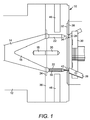
図面を参照して、図1は、ペレット製造機の構成要素に関連した本発明の一実施形態を示す。ペレット製造機は、溶融装置および/または混合装置(図示せず)からの流入ハウジング12を含む。流入ハウジング12は、有機物、オリゴマー、ポリマー、ワックス、およびそれらの組み合わせに限定されないが、これらを含み得る溶融物または他の押出成形品(以下、まとめて「溶融プロセス品」とする)のための流路14を含む。円錐部16は、円錐部16がねじ切りされたロッド(図示せず)によって装着接合される一体式押出ダイ10の上流側へと、溶融プロセス品を方向付ける。ねじ切りされたロッドは、その一端が円錐部16のねじ穴18へとねじ止めされ、他端が一体式押出ダイ10のねじ穴20へとねじ止めされる。あるいは、円錐部16は、一体式押出ダイ10と一体であってもよく、本明細書に記載のように装着接合しなくてもよい。
Referring to the drawings, FIG. 1 illustrates one embodiment of the present invention associated with components of a pelletizer. The pelletizer includes an
一体式押出ダイ10は、少なくとも1つ、好ましくは複数の型孔22を含む。当該型孔22は、単独で、または複数が少なくとも1つのリング状となるように同心状に配置され、一体式押出ダイ10の上流面24から下流面26へと延びている。切断チャンバ(図示せず)内の回転駆動カッターハブ30に搭載された複数のナイフ刃アセンブリ28は、押出成形され、冷却され、少なくとも部分的に固化した溶融プロセス品を切断して、ペレットを形成する。このように形成されたペレットは、機械的手段、空圧、流体圧、およびそれらの組み合わせで下流処理へと運ばれる。
The monolithic extrusion die 10 includes at least one, preferably a plurality of mold holes 22. The mold holes 22 are arranged singly or concentrically so as to form at least one ring shape, and extend from the
下流面26の領域を任意で切り欠いて、型孔22に周囲が隣接する少なくとも1つの円環状の凹部すなわち窪み32を形成し、一体式押出ダイ10のベースプレート36と連続する凸部34に型孔22が収まるようにしてもよい。凸部34の有無にかかわらず、型孔22内には、以下に詳説する同数のインサート50が配置される。円環状のカバープレート38を、円環状の凹部すなわち窪み32に被せて、ロウ付け、溶接、または当業者に公知の同様の技術によって、ベースプレート36および凸部34に装着接合する。カバープレート38は、好ましくはニッケル鋼等の耐摩擦耐食金属、好ましくは炭化タングステン等の硬質面材、および数多くのそれらの組み合わせのうちの少なくとも1つからなっていてもよい。同様に、カバープレート38のベースプレート36および/または凸部34への装着は、溶接、ロウ付け等によってなされることが好ましい。カバープレート38の表面、ひいては、一体式押出ダイ10の下流面26は、当業者に公知のように、耐薬品、耐摩擦、耐食、かつ耐摩耗の被膜で任意で被覆されていてもよい。
A region of the
図2は、本発明の第2の実施形態における着脱入れ子式押出ダイアセンブリ100を示す。着脱入れ子式押出ダイアセンブリ100は、ベースプレート105および着脱式入れ子110を含む。図1と同様に、着脱入れ子式押出ダイアセンブリ100は、溶融装置および/または混合装置(図示せず)からの流入ハウジング12に装着接合される。流入ハウジング12は、上記のように、溶融プロセス品のための流路14を含む。円錐部16は、円錐部16がねじ切りされたロッド(図示せず)によって装着接合される着脱式入れ子110の上流側へと、溶融プロセス品を方向付ける。ねじ切りされたロッドは、その一端が円錐部16のねじ穴118へとねじ止めされ、他端が着脱式入れ子110のねじ穴120へとねじ止めされる。
FIG. 2 shows a removable telescoping die
着脱式入れ子110は、少なくとも1つ、好ましくは複数の型孔22を含む。当該型孔22は、単独で、または複数が少なくとも1つのリング状となるように同心状に配置され、着脱式入れ子110の上流面124から下流面126へと延びている。切断チャンバ(図示せず)内の回転駆動カッターハブ30に搭載された複数のナイフ刃アセンブリ28は、押出成形され、冷却され、少なくとも部分的に固化した溶融プロセス品を切断して、ペレットを形成する。このように形成されたペレットは、上記のように、機械的手段、空圧、流体圧、およびそれらの組み合わせで下流処理へと運ばれる。
The
下流面126の領域を任意で切り欠いて、型孔22に周囲が隣接する少なくとも1つの円環状の凹部すなわち窪み132を形成し、着脱式入れ子110の着脱式中央ベースプレート136と連続する凸部134に型孔22が収まるようにしてもよい。凸部134の有無にかかわらず、型孔22内には、以下に詳説する同数のインサート50が配置される。円環状のカバープレート138を、円環状の凹部すなわち窪み132に被せて、ロウ付け、溶接、または当業者に公知の同様の技術によって、着脱式中央ベースプレート136および凸部134に装着接合する。カバープレート138は、好ましくはニッケル鋼等の耐摩擦耐食金属、好ましくは炭化タングステン等の硬質面材、および数多くのそれらの組み合わせのうちの少なくとも1つからなっていてもよい。同様に、カバープレート138の着脱式中央ベースプレート136および/または凸部134への装着は、溶接、ロウ付け等によってなされることが好ましい。カバープレート138の表面、ひいては、着脱式入れ子110の下流面126は、当業者に公知のように、耐薬品、耐摩擦、耐食、かつ耐摩耗の被膜で任意で被覆されていてもよい。
A region of the downstream surface 126 is optionally cut out to form at least one annular recess or
加熱および/または冷却プロセスは、一体式押出ダイ10および着脱入れ子式押出ダイアセンブリ100に関して従来開示されてきたように、電気抵抗、誘導、蒸気、または伝熱流体によって実施できる。あるいは、着脱式入れ子110およびベースプレート105を、同様または異なるメカニズムによって、別々に加熱することもできる。加熱部材46は、図1および図2にそれぞれ示すように、一体式押出ダイ10または着脱入れ子式押出ダイアセンブリ100に挿入されていることが好ましい。当業者に公知の他の設計も参照により本明細書に援用されるが、これらに限定されない。
The heating and / or cooling process can be performed by electrical resistance, induction, steam, or heat transfer fluid as previously disclosed with respect to the integral extrusion die 10 and the removable telescoping die
次いで、一体式押出ダイ10を示す図3を参照して、上流面24から、ベースプレート36に任意で形成される凸部34内へと延びてこれを通過し、カバープレート38の下流面26まで延びる型孔22内に、インサート50が示されている。説明を明確にするために、任意で形成される円環状の凹部すなわち窪み32も示されている。同様のアセンブリが着脱式入れ子110にも適用されるが、図示を省略する。
Next, referring to FIG. 3 showing the integral extrusion die 10, the
図4は、一実施形態に係るインサート50の構造を詳細に示す。図4に示すように、インサート50aは、マンドレル52、複数のインサートフィンテーパ54、および複数のフィン56を含む。インサート50aは、いかなる耐摩耗材からなっていてもよいが、好ましくは金属からなる。当該金属は、アルミニウム、真鍮、青銅、銅、鋼鉄、工具鋼、炭素鋼、バナジウム鋼、ステンレス鋼、ニッケル鋼、ニッケル等に限定されないが、これらを含み得る。より好ましくは、当該金属は、真鍮、青銅、および銅を含む、熱の良導体である。いかなる理論にも限定されるものではないが、熱伝導性金属は、型孔22に進入してこれを通過する溶融プロセス品の温度を均一に維持すると考えられている。これは、複数のフィン56によって形成される複数の流路を物質が流れる際の熱損失および/または温度変化を最小とするのに有効である。
FIG. 4 shows in detail the structure of the
インサート50aの寸法は、処理温度において型孔22の寸法を超えないものでなくてはならない。インサート50aの金属がベースプレート36または着脱式入れ子110の金属とは異なる場合、伸び差を考慮しなくてはならない。フィン56は、溶融プロセス品のための複数の流路を形成するだけではなく、インサート50aの型孔22内での位置を維持する役割を果たす。フィンの最小数は、少なくとも2つであり、好ましくは少なくとも3つである。より好ましくは、インサート50aには少なくとも4つのフィン56が配置される。複数のフィン56は、溶融ポリマーが流れる流路を形成するために、隣接するフィンに対していかなる角度に向けられてもよい。好ましくは、フィン同士の間は、180度以下である。より好ましくは、フィン同士の間は、120度以下である。最も好ましくは、フィン同士の間は、90度以下である。その結果、場合によっては、インサートは、インサート50aの周りに少なくとも4つのフィンを有し、当該少なくとも4つのフィンのそれぞれは、隣接するフィンとの間が約90度以下となる。
The dimensions of the
図5は、ダイオリフィスまたは型孔22内のインサート50aを示す。図示されるように、マンドレル52は、ダイランド60内にほぼ含まれ、インサートフィンテーパ54は、その寸法が型孔テーパ62にほぼ相当し、フィン56は、プレランドチューブ64内にほぼ含まれる。ダイランド60の長さは、一般的に少なくともおよそ3.8mm(およそ0.15インチ)〜およそ31.75mm(およそ1.25インチ)であり、好ましくは少なくともおよそ6.4mm(およそ0.25インチ)〜およそ25mm(およそ1.00インチ)である。ダイランド60内のマンドレル52は、押出ダイの下流面と面一であることが好ましい。別の実施形態において、マンドレル52の長さは、ダイランド60の長さ未満であってもよい。このような別の実施形態において、マンドレル52の長さは、ダイランド60の長さより、最大約0.50mm(およそ0.020インチ)〜約5.0mm(およそ0.20インチ)だけ短く、マンドレル52の先端が、押出ダイの下流面からごく僅かに凹むことになる。ダイランド60および/またはマンドレル52は、円筒状またはテーパ状であってもよく、その形状が円形、楕円形、長方形等であってもよい。同様に、ダイランド60とマンドレル52とは、形状が同様であっても異なっていてもよい。インサート50aは、型孔22へ圧入されてもよいが、好ましくはスライドして嵌合される。
FIG. 5 shows the
インサートフィンテーパ54は、型孔テーパ62と角度66が同様である。型孔テーパ62は、プレランドチューブ64の直径上に仮定される垂直円筒に対して型孔テーパ62との接続部で計測された場合に、0°〜90°の角度であり得る。好ましくは、角度66は、本明細書に記載のように15°〜45°である。インサートフィンテーパ54の輪郭は、型孔テーパ62の輪郭と同一でも異なっていてもよいが、その寸法はフィン56の直径からマンドレル52の直径までテーパ状でなくてはならない。同様に、フィン56の形状は、例えば、円筒状、テーパ状、またはそれらの組み合わせであるプレランドチューブ64の形状と同一でも異なっていてもよい。好ましくは、プレランドチューブ64およびフィン56は、円筒状である。フィン56の長さは、プレランドチューブ64の長さと同一であってもよいが、好ましくはプレランドチューブ64の長さ未満である。より好ましくは、フィンがプレランドチューブ64の長さを超えて外部へ突出しないように、フィン56の長さは、プレランドチューブ64の長さより少なくともおよそ0.50mm(およそ0.020インチ)だけ短くする。
The
図5aは、プレランドチューブ64内におけるフィン56を線aに沿って例示する断面図である。図5bは、型孔テーパ62内におけるインサートフィンテーパ54を線bに沿って例示する断面図である。図5cは、ダイランド60内におけるインサートフィンテーパ54への装着位置におけるマンドレル5を、線cに沿って例示する断面図である。図5dは、ダイランド60内における任意で先細りのテーパ状とされるマンドレル52を線dに沿って例示する断面図である。
FIG. 5 a is a cross-sectional view illustrating the
図6a〜図6cは、別の実施形態に係るインサート50の構造を詳細に示す。まず図6aを参照して、インサート50bは、後方部70および前方部72を含む。後方部70は、カン74を含む。前方部72は、複数のフィン78および複数のフィンテーパ80を含むマンドレル76を含む。インサート50bの後方部70のカン74は、後縁82および中空キャビティ84を含む。後縁82は、溶融プロセス品を受け入れるように開口している。後縁82と中空キャビティ84との間には、任意でねじ山86が形成される。ねじ山86は、例えば、器具をねじ山86に挿入し、インサート50bを掴んで型孔22から取り外したり型孔22に取り付けたりすることによって、インサート50bを型孔22に脱着するのに用いることができる。この任意のねじ山の有用な特徴は、最小限の投資で、ペレット製造処理を、中空ペレット製造から通常の非中空(中実)ペレット製造へと切り替え、さらに逆方向の切り替えを行うことができるという柔軟性にある。
6a to 6c show in detail the structure of the
カン74の中空キャビティ84は、前方壁88を含む。前方壁88は、図6aに示すように平坦であってもよい。前方壁88は、少なくとも1つの孔90を含む。前方壁88は、少なくとも2つの孔90、少なくとも3つの孔90、または少なくとも4つの孔90を含んでいてもよい。あるいは、前方壁88が平坦ではなく、図6bに示すように当該領域に複数のテーパ状流入口91を含んでいてもよい。テーパ状流入口91は、溶融物を少なくとも1つの孔90へ流し込み、溶融物が前方壁88で溜まらないようにするのに役に立つ。
The
再び図6aを参照して、少なくとも1つの孔90は、中空キャビティ84の前方壁88から、インサート50bの後方部70の前方壁92まで延びている。少なくとも1つの孔90によって、溶融プロセス品の流れを阻害したり圧力を不要に増加させたりすることなしに、溶融プロセス品を中空キャビティ84から流し、インサート50bの前方部72へと送ることができる。前方壁92は、面取り部94を任意で含んでいてもよい。
Referring again to FIG. 6a, at least one
図6cは、インサート50bを前方からみた透視図であり、マンドレル76、マンドレル76上の複数のフィン78、および複数のフィンテーパ80を含む、インサート50bの前方部72をより明らかに示す。マンドレル76は、少なくとも3つの別々の領域であるところの、ベース領域102、中間領域104、および前方領域106を有することが好ましい。ベース領域102において、フィン78は、後方部70の前方壁92から前方領域106および押出ダイの下流面へとマンドレル76に沿って前方に延びている。これによって、溶融プロセス品を、少なくとも1つの孔90を通って流れさせることができ、少なくとも1つの孔90を通ってフィン78に沿った一定の層流や他の望ましい流れを維持することができる。フィン78は、溶融プロセス品の流れを阻害することなしに、溶融プロセス品を誘導する役割を果たす。中間領域104において、フィン78は、凸部108を有する。フィン78は、マンドレル76の中間領域内のフィンテーパ80で終わりとなる。インサートフィンテーパ80は、フィン78の直径からフィン78のないマンドレル76の直径までテーパ状となる。したがって、マンドレル76の前方領域106は、フィンを有していなくてもよい。前方領域106にフィンがない場合、溶融プロセス品が型孔22から押し出されると、結果として得られる中空ペレットが、フィン78がマンドレル76の先端112まで伸びている場合に生じるような隙間なしに完全に形成可能であるように、マンドレル76の前方領域106の周囲に溶融プロセス品を流すことができる。
FIG. 6 c is a perspective view of the
マンドレル76上に配置されるフィン78の最小数は、少なくとも2つであり、少なくとも3つである場合もある。いくつかの実施形態において、少なくとも4つのフィン78がマンドレル76上に配置される。マンドレル76上の複数のフィン78は、溶融ポリマーが流れる流路を形成するために、隣接するフィンに対していかなる角度に向けられてもよい。フィン78同士の間は、等間隔に配置され得る。したがって、フィン78同士の間は、マンドレル76の周りに約180度以下であってもよく、マンドレル76の周りに約120度以下であってもよく、隣接するフィンとの間がマンドレルの周りに約90度以下であってもよい。
The minimum number of
次いで、図7aを参照して、インサート50bは型孔22内に示されている。インサート50bの寸法は、処理温度において型孔22の寸法を超えないものでなくてはならない。インサート50bの金属がベースプレート36または着脱式入れ子110の金属とは異なる場合、伸び差を考慮しなくてはならない。
Then, referring to FIG. 7 a, the
フィン78は、溶融プロセス品のための複数の流路を形成するだけではなく、マンドレル76の型孔22内での位置を維持する役割を果たす。型孔22内の圧力または流れの差、および/または刃28を有するカッターハブ30を回転する力によって、マンドレル76に力が伝えられ、マンドレル76が動き得ることになる。マンドレル76上のフィン78は、マンドレル76をさらに支持して安定させ、マンドレル76を型孔22内でしっかりと保持し、マンドレル76の望ましくない動きを防ぐことができる。凸部108は、型孔22に当接して、マンドレル76の型孔22内での位置を維持することを補助する。
The
インサート50bは、マンドレル76の中間領域104および前方領域106がダイランド60内にほぼ含まれるように、型孔22内に配置される。同図に示すように、型孔テーパ62は、2つの領域114および116を含み得る。領域114は、任意で湾曲(図示)していてもよいし、平坦(図示せず)であってもよい。同様に、領域116は、直線のテーパ状で斜めの領域(図示)であってもよいし、平坦(図示せず)であってもよい。フィン78は、型孔テーパ62を通ってダイランド60内へと延び、凸部108がダイランド60に当接してマンドレル76の位置を維持することができる。
The
また、ダイランド60の長さは、一般的に少なくともおよそ3.8mm(およそ0.15インチ)〜およそ31.75mm(およそ1.25インチ)であり、好ましくは少なくともおよそ6.4mm(およそ0.25インチ)〜およそ25mm(およそ1.00インチ)である。ダイランド60内のマンドレル76は、押出ダイの下流面と面一であることが好ましい。別の実施形態において、マンドレル76の長さは、ダイランド60の長さ未満であってもよい。このような別の実施形態において、マンドレル76の長さは、ダイランド60の長さより、最大約0.50mm(およそ0.020インチ)〜約5.0mm(およそ0.20インチ)だけ短く、マンドレル76の先端112が、押出ダイの下流面からごく僅かに凹むことになる。
Also, the length of the
ダイランド60とマンドレル76とは、形状が同様であっても異なっていてもよい。ダイランド60は、円筒状またはテーパ状であってもよく、その形状が円形、楕円形、長方形、星形等であってもよい。マンドレル76は、円筒状またはテーパ状であってもよく、その形状が円形、楕円形、長方形、星形等であってもよい。フィン78を介した前方部72は、圧入プラグであってもよく、好ましくは型孔22へと圧入される。
The die
図7bおよび図7cは、別の実施形態に係る、型孔22内のインサート50bを詳細に示す。図7bは、インサートを後方上部からみた透視図であり、図7cは、インサートを前方からみた透視図である。図示されるように、マンドレル76は、凸部118を含む。前方壁88が1つより多い孔90を含む場合、凸部118は、孔90から流出するポリマーの流れを、もとの単一で均一な流れにするために用いられてもよい。凸部118は、溶融した流れが凸部118上を通り過ぎる際に、溶融した流れを凸部118と型孔22の壁部120との間で外側に押すという作用を為し、それによって、溶融物が複数の流れではなく単一で均一な流れとなる。
Figures 7b and 7c show in detail an
インサート50bは、いかなる耐摩耗材からなっていてもよいが、好ましくは金属からなる。当該金属は、アルミニウム、真鍮、青銅、銅、鋼鉄、工具鋼、炭素鋼、バナジウム鋼、ステンレス鋼、ニッケル鋼、ニッケル等に限定されないが、これらを含み得る。いくつかの実施形態において、当該金属は、真鍮、青銅、および銅を含む、熱の良導体であってもよい。いかなる理論にも限定されるものではないが、熱伝導性金属は、型孔22に進入してこれを通過する溶融プロセス品の温度を均一に維持すると考えられている。これは、複数のフィン78によって形成される複数の流路を物質が流れる際の熱損失および/または温度変化を最小とするのに有効である。好ましくは、当該金属として、熱伝導率が低い、より良好な熱絶縁材であるステンレス鋼等の、強度および耐摩耗性が高いものが選択される。
The
一実施形態において、インサートは、カンおよびマンドレルを含む一体型アセンブリであってもよい。別の実施形態において、マンドレルがカンから分離している複合型アセンブリであってもよい。図8a〜図8cに、インサートの複合型アセンブリを示す。まず図8aを参照して、図示されるように、インサート50bは、カン74およびマンドレル76を含む。この複合型の実施形態において、マンドレル76は、カン74から取り外し可能である。図8bに示すように、マンドレル76は、カン74に螺合されてもよい。あるいは、マンドレルは、カンに何らかの別の手法で装着接合されてもよい。図8cは、マンドレル76がカン74に装着された状態の複合型アセンブリを前方からみた斜視図である。
In one embodiment, the insert may be a unitary assembly that includes a can and a mandrel. In another embodiment, it may be a composite assembly where the mandrel is separated from the can. 8a-8c show a composite assembly of inserts. Referring first to FIG. 8 a, as shown, the
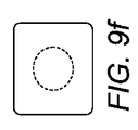
図9a〜図9iは、本発明に従って形成された中空ペレットの種々の形状を示す。図9aは、中空キャビティが完全に貫通している円筒状ペレットの上面図を示す。図9bは、図9aの中空円筒状ペレットの断面図を示し、図9cは、同一ペレットの側面図を示す。図9dは、略球体状ペレットの上面図を示し、図9eは、当該ペレットの断面図を示す。図9fは、略直方体状ペレットの上面図を示し、図9gは、該ペレットの断面図であり、当該直方体状ペレット内に球体状の中空キャビティを有する構成を示す。図9hは、略球体状ペレットの上面図を示し、図9iは、該ペレットの断面図であり、ペレット壁内へと延びてこれを通過する孔部を有するキャビティを示す。数多くのペレット形状およびキャビティ形状が、限定を受けることなく本発明の方法によって実現できることが当業者には理解されよう。 Figures 9a to 9i show various shapes of hollow pellets formed in accordance with the present invention. FIG. 9a shows a top view of a cylindrical pellet with a hollow cavity fully penetrating. FIG. 9b shows a cross-sectional view of the hollow cylindrical pellet of FIG. 9a, and FIG. 9c shows a side view of the same pellet. FIG. 9d shows a top view of a substantially spherical pellet and FIG. 9e shows a cross-sectional view of the pellet. FIG. 9f shows a top view of a substantially rectangular parallelepiped pellet, and FIG. 9g is a cross-sectional view of the pellet, showing a configuration having a spherical hollow cavity in the rectangular parallelepiped pellet. FIG. 9h shows a top view of the generally spherical pellet, and FIG. 9i is a cross-sectional view of the pellet showing a cavity with a hole extending into and through the pellet wall. Those skilled in the art will appreciate that numerous pellet and cavity shapes can be realized by the method of the present invention without limitation.
中空ペレットの形成は、溶融レオロジー、特に溶融粘度によって大いに制御される。部分的な溶融物は、一般的に、上記した図9a〜図9cに示すような円環体すなわちドーナツ型のペレットを形成する。溶融粘度の低下に従ってメルトフローインデックスが上昇すると、ペレットがより閉じられるようになり、図9d〜図9gに示すような完全に包み込まれたキャビティを形成する。溶融粘度のさらなる低下に従ってメルトフローインデックスが上昇すると、包み込まれる程度が完全ではないキャビティが形成されて孔部が生じ、最終的にはキャビティが崩壊するか部分的に崩壊して、不規則なキャビティが形状されることになる。 The formation of hollow pellets is largely controlled by melt rheology, particularly melt viscosity. The partial melt generally forms a torus or donut shaped pellet as shown in FIGS. 9a-9c described above. As the melt flow index increases with decreasing melt viscosity, the pellets become more closed, forming a fully encapsulated cavity as shown in FIGS. 9d-9g. As the melt flow index increases as the melt viscosity further decreases, cavities are formed that are not fully encapsulated, resulting in pores that eventually collapse or partially collapse, resulting in irregular cavities Will be shaped.
さらに、化学組成、融点範囲、および結晶度等の要素は、溶融プロセス品の流動性および温度に影響を与えるため、これらの要素も重要である。結晶化は、一般的に発熱を伴い、溶融処理温度を上昇させるため、粘度を低下させる。融点範囲が狭まるに従って、固化を著しく促進させるための冷却の必要性が少なくなるため、キャビティが完全に貫通している円環体すなわちドーナツ型のペレットと比較して、完全に包み込まれたキャビティの形成がより難しくなる。ポリマーの極性、分岐性、および疎水性/親水性相互作用は、融液相や固化を生じさせるプロセスの特性に影響を与える。ダイから流出する際の物質の膨張性は、特定の直径のキャビティを含む所望の直径のペレットを実現するために必要なマンドレルとダイランドと直径差や、ペレットの閉じ度を評価するのに重要な要素である。溶融粘度が低下するのに従って、これらの変数の制御が低下し、結晶の温度による影響が存在する場合、当該影響が増大する。 In addition, factors such as chemical composition, melting point range, and crystallinity also affect the flowability and temperature of the melt process product, so these factors are also important. Crystallization generally generates heat and raises the melt processing temperature, thus lowering the viscosity. As the melting point range narrows, the need for cooling to significantly accelerate solidification decreases, so that a fully encapsulated cavity can be compared to a torus or donut-shaped pellet with a fully penetrating cavity. Formation becomes more difficult. Polymer polarity, branching, and hydrophobic / hydrophilic interactions affect the properties of the process that causes the melt phase and solidification. The expansibility of the material as it flows out of the die is important for evaluating the mandrel and die land diameter differences required to achieve pellets of the desired diameter, including cavities of a specific diameter, and the degree of pellet closure. Is an element. As the melt viscosity decreases, the control of these variables decreases and increases if there is an effect due to the temperature of the crystal.
吸湿は、ペレット製造が好適な水中ペレット製造によって行われる場合の水分の取り込み性を明らかにするための手段として、評価される。形成された中空キャビティ内において、輸送流体、好ましくは水の取り込みが生じている場合、水分が比例的に高くなることが予期される。驚くべきことに、低質量の中空ペレットと同程度の直径を有する中実ペレットとの質量差を考慮すると、水分含有率が予想よりも大幅に低く、さらに驚くべきことに、材料の極性が上昇するのに従って水分がより低下することが分かった。例えば、ポリエチレンおよびポリプロピレンの中空ペレットは両方とも、同程度の直径の中実ペレットと同程度の水分含有率である一方、エチルビニルアセテートの中空ペレットは、水分が中実ペレットのおよそ1/2〜2/3であることが分かった。 Moisture absorption is evaluated as a means to reveal moisture uptake when pellet production is performed by suitable underwater pellet production. If the transport fluid, preferably water, is taken up within the formed hollow cavity, it is expected that the moisture will be proportionally higher. Surprisingly, considering the mass difference between a low-mass hollow pellet and a solid pellet with the same diameter, the moisture content is much lower than expected, and surprisingly, the polarity of the material increases It has been found that the water content decreases as the process proceeds. For example, both polyethylene and polypropylene hollow pellets have a moisture content comparable to solid pellets of similar diameter, whereas ethyl vinyl acetate hollow pellets have a moisture content of approximately 1/2 to that of solid pellets. It was found to be 2/3.
本発明に係る中空ペレットを製造するのに用いられる物質は、例えば、ポリマー、コポリマー、バイオポリマー、およびバイオプラスチック、ならびにそれらの組み合わせに限定されないが、これらを含む。 The materials used to make the hollow pellets according to the present invention include, but are not limited to, for example, polymers, copolymers, biopolymers, and bioplastics, and combinations thereof.
本発明に係る中空ペレットを製造するのに有用なポリマーは、ポリオレフィン、架橋性ポリオレフィン、ポリアミド、ポリイミド、ポリエステル、ポリカーボネート、ポリスルフィド、ポリスルホン、ポリウレタン、ポリエーテル、ポリチオエーテル、ワックス、ホットメルト接着剤、アスファルト、熱可塑性エラストマー、ゴム、セルロース化合物、ガム基礎剤、芳香族ビニルポリマーおよび脂肪族ビニルポリマーを含むビニルポリマーや置換ビニルポリマー、ポリスチレン等の芳香族アルケニルポリマー、ならびにこれらのコポリマーであってもよい。 Polymers useful for producing the hollow pellets according to the present invention are polyolefins, crosslinkable polyolefins, polyamides, polyimides, polyesters, polycarbonates, polysulfides, polysulfones, polyurethanes, polyethers, polythioethers, waxes, hot melt adhesives, asphalts , Thermoplastic elastomers, rubbers, cellulose compounds, gum bases, vinyl polymers including aromatic vinyl polymers and aliphatic vinyl polymers, substituted vinyl polymers, aromatic alkenyl polymers such as polystyrene, and copolymers thereof.
最終的に得られる中空ペレット、あるいは他のバイオまたは非バイオポリマーや物質を含むもしくは含まない組成物の構成要素としてのバイオプラスチックは、例えば、ポリヒドロキシアルカノエート、ポリグリコライド、ポリラクチド、ポリエチレングリコール、多糖類、セルロース化合物、スターチ、ポリ無水物、脂肪族ポリエステル、ポリカーボネート、ポリオルトエステル、ポリホスファゼン、ポリラクトン、およびポリラクタムに限定されないが、これらを含む。 Bioplastics as components of the final resulting hollow pellets or compositions with or without other bio- or non-biopolymers or substances include, for example, polyhydroxyalkanoates, polyglycolides, polylactides, polyethylene glycols, Including, but not limited to, polysaccharides, cellulose compounds, starches, polyanhydrides, aliphatic polyesters, polycarbonates, polyorthoesters, polyphosphazenes, polylactones, and polylactams.
本発明に有用なポリオレフィンは、超低密度ポリエチレン、直鎖低密度ポリエチレン、低密度ポリエチレン、中密度ポリエチレン、高密度ポリエチレン、ポリブチレン、イオノマー、ポリメチルペンテン、ポリプロピレン、エチレン−ビニルアセテート、アルキルおよびアリール置換ビニル化合物、ハロゲン化およびポリハロゲン化ビニル化合物、ポリビニルエステル、ポリビニルアルコール、ならびにこれらのコポリマーであってもよい。 Polyolefins useful in the present invention are ultra low density polyethylene, linear low density polyethylene, low density polyethylene, medium density polyethylene, high density polyethylene, polybutylene, ionomer, polymethylpentene, polypropylene, ethylene-vinyl acetate, alkyl and aryl substituted. Vinyl compounds, halogenated and polyhalogenated vinyl compounds, polyvinyl esters, polyvinyl alcohol, and copolymers thereof may be used.
本発明に係る中空ペレットの製造において、溶融物には、1以上の添加物が含まれていてもよい。添加物の組成は、レオロジー改質剤、架橋促進剤、酸化防止剤、紫外線安定剤、熱安定剤、色素、顔料、充填剤、繊維、核化剤、膨張剤、カプセル化された農業上および製薬上の有効成分、着香剤および香料、粘着付与剤、脱粘着剤、ペレット被膜、可塑剤、滑沢剤、ワックス、バイオ物質添加物(セルロース化合物、スターチ、およびタンパク様物質に限定されないが、これらを含んでいてもよい)、カップリング剤、バインダー、捕集剤、相乗剤、加工助剤、およびペレット化助剤に限定されないが、これらを含み得る。当該1以上の添加物は、単独であってもよいし、複数の組み合わせであってもよい。 In the production of the hollow pellet according to the present invention, the melt may contain one or more additives. The composition of the additive includes rheology modifiers, crosslinking accelerators, antioxidants, UV stabilizers, heat stabilizers, dyes, pigments, fillers, fibers, nucleating agents, swelling agents, encapsulated agricultural and Pharmaceutical active ingredients, flavorings and fragrances, tackifiers, detackifiers, pellet coatings, plasticizers, lubricants, waxes, biomaterial additives (but not limited to cellulose compounds, starches, and proteinaceous materials) These may include, but are not limited to, coupling agents, binders, scavengers, synergists, processing aids, and pelletizing aids. The one or more additives may be used alone or in combination.
本発明に有用なポリマー、コポリマー、および1以上の添加物は、アモルファス、結晶体、またはそれらの組み合わせであってもよい。ポリマー、コポリマー、および1以上の添加物は、反応性官能基を含み得る。反応性官能基は、架橋性のものであってもよい。反応性官能基は、膨張を含む化学反応によって改質されてもよい。 The polymers, copolymers, and one or more additives useful in the present invention may be amorphous, crystalline, or combinations thereof. The polymer, copolymer, and one or more additives can include reactive functional groups. The reactive functional group may be crosslinkable. The reactive functional group may be modified by chemical reactions including swelling.
押出プロセスにおける背圧は、インサートを用いることによって増加することが見込まれるが、ダイ孔の数を増加すること、溶融プロセス品の温度を上昇させること、およびダイの温度を上昇させることのうちの少なくとも1つによって緩和できることが分かった。当業者には理解できるように、これらの要素は驚きに値する結果ではない。 The back pressure in the extrusion process is expected to increase with the use of inserts, including increasing the number of die holes, increasing the temperature of the melt process product, and increasing the temperature of the die. It has been found that it can be mitigated by at least one. As those skilled in the art can appreciate, these factors are not surprising.
いかなる理論にも限定されるものではないが、本発明に従って製造された中空ペレットは、通常の中実ペレットよりも高い表面積−体積比および短い外表面−「核」距離を有するため、中空ペレットは、中実ペレットと比較していくつかの利点を有する。例えば、中空ペレットは、より早く溶融するだけではなく、より早く乾燥、結晶化、および/または固体重合するため、中空ペレットを用いることによって生産性が向上する。形成後、ペレットが溶媒に投入される場合もあるが、中空ペレットは、通常の中実ペレットより速く溶融する。中空ペレットは、化合前混合物における混合および分散特性も高いため、押出成形や他の用途に用いる前に、他の物質と乾式混合することがより容易になる。場合によっては、衝撃エネルギーを吸収したり総重量を低減したりする等の機能を達成するのに、より安価なペレットが必要となるが、中空ペレットによってこれが実現される。さらに、ペンタン等の膨張剤が溶融物に含まれてもよく、結果として得られるペレットが、「発泡ドーナツ」等の形状に膨張して、パッキング用途に直接使用できるようになる。 Without being limited to any theory, hollow pellets made in accordance with the present invention have a higher surface area-volume ratio and shorter outer surface- "nuclear" distance than normal solid pellets, so hollow pellets are Has several advantages compared to solid pellets. For example, hollow pellets not only melt faster, but also dry, crystallize, and / or solid polymerize faster, so using hollow pellets increases productivity. After formation, the pellets may be charged into the solvent, but the hollow pellets melt faster than normal solid pellets. Hollow pellets also have high mixing and dispersion properties in the pre-combination mixture, making it easier to dry mix with other materials prior to use in extrusion and other applications. In some cases, cheaper pellets are required to achieve functions such as absorbing impact energy and reducing total weight, but this is achieved with hollow pellets. In addition, an expansion agent such as pentane may be included in the melt, and the resulting pellets expand into a shape such as a “foamed donut” and can be used directly for packing applications.
以上の記載は、本発明の原理を単に説明しているにすぎない。また、当業者による様々な変形や変更が容易に可能であるため、本発明は、図示され記載された実施形態そのものに限定されるものではない。したがって、あらゆる適切な変形およびその等価物が本発明の範囲に含まれることはいうまでもない。 The above description merely illustrates the principles of the invention. Further, since various modifications and changes can be easily made by those skilled in the art, the present invention is not limited to the illustrated and described embodiments themselves. Therefore, it is needless to say that all appropriate modifications and equivalents are included in the scope of the present invention.
Claims (11)
溶融物をペレット製造機へ供給する工程と、
前記ペレット製造機の押出ダイを通じて前記溶融物を押出成形する工程と、を備え、
当該押出成形工程の間、前記溶融物が、インサートの中空カンを通り、前記インサートの少なくとも1つの孔を通り、前記インサートのマンドレル上に配置されるフィンの周囲を流れ、前記フィンは、前記インサートが配置される押出ダイ内において、前記マンドレルの外表面からダイオリフィスの内表面に当接するように延びている、プロセス。 An extrusion process for producing hollow pellets,
Supplying the melt to a pellet making machine;
A step of extruding the melt through an extrusion die of the pellet making machine,
During the extrusion process, the melt flows through a hollow can of the insert, through at least one hole of the insert, around a fin disposed on the mandrel of the insert, the fin being inserted into the insert A process that extends from the outer surface of the mandrel to abut the inner surface of the die orifice within the extrusion die in which
溶融物を受け入れる流入口と、
流入口の後段に配置され、前記溶融物を押出成形する型孔と、
前記型孔内に配置されるインサートであって、後方部および前方部を含み、前記後方部は中空カンを含み、前記前方部はマンドレルを含み、前記マンドレルは複数のフィンを含み、前記フィンは、前記インサートが配置される押出ダイ内において、前記マンドレルの外表面からダイオリフィスの内表面に当接するように延びており、前記インサートは、前記溶融物を前記中空カンから前記マンドレルへと流すことができるように構成された少なくとも1つの孔をさらに含む、インサートと、を備え、
前記ペレット製造機は、流体中ペレット製造機である、ペレット製造機。 A pellet making machine for producing hollow pellets,
An inlet for receiving the melt,
A mold hole arranged at the rear stage of the inlet and for extruding the melt;
An insert disposed in the mold cavity, comprising a rear part and a front part, wherein the rear part comprises a hollow can, the front part comprises a mandrel, the mandrel comprises a plurality of fins, Extending from the outer surface of the mandrel in contact with the inner surface of the die orifice in the extrusion die in which the insert is disposed, the insert flowing the melt from the hollow can to the mandrel An insert further comprising at least one hole configured to allow
The said pellet manufacturing machine is a pellet manufacturing machine which is a pellet manufacturing machine in fluid.
Applications Claiming Priority (1)
| Application Number | Priority Date | Filing Date | Title |
|---|---|---|---|
| PCT/US2014/055583 WO2016043694A1 (en) | 2014-09-15 | 2014-09-15 | Method and device for extrusion of hollow pellets |
Publications (3)
| Publication Number | Publication Date |
|---|---|
| JP2017530877A JP2017530877A (en) | 2017-10-19 |
| JP2017530877A5 JP2017530877A5 (en) | 2017-11-30 |
| JP6383865B2 true JP6383865B2 (en) | 2018-08-29 |
Family
ID=55533586
Family Applications (1)
| Application Number | Title | Priority Date | Filing Date |
|---|---|---|---|
| JP2017514302A Active JP6383865B2 (en) | 2014-09-15 | 2014-09-15 | Hollow pellet extrusion method and apparatus |
Country Status (6)
| Country | Link |
|---|---|
| EP (1) | EP3194141B1 (en) |
| JP (1) | JP6383865B2 (en) |
| KR (1) | KR102290338B1 (en) |
| CN (1) | CN106687276B (en) |
| BR (1) | BR112017005091A2 (en) |
| WO (1) | WO2016043694A1 (en) |
Families Citing this family (5)
| Publication number | Priority date | Publication date | Assignee | Title |
|---|---|---|---|---|
| EP3511139B1 (en) | 2018-01-12 | 2022-08-31 | Nordson Corporation | Nozzle assembly for granulating device, granulation device, and related method |
| WO2020009866A1 (en) * | 2018-07-03 | 2020-01-09 | Corning Incorporated | Extrusion device having a fixed profile |
| DE102019107140B4 (en) | 2019-03-20 | 2023-06-29 | Nordson Corporation | Nozzle arrangement with pressure regulating device and granulating device |
| CN114653304B (en) * | 2022-04-01 | 2022-11-01 | 联合优发生物质能源徐州有限公司 | Novel biomass particle granulating and forming machine |
| CN116139775B (en) * | 2022-12-27 | 2023-10-03 | 江苏久久和牧农牧科技有限公司 | Piglet feed granulating device and granulating process thereof |
Family Cites Families (14)
| Publication number | Priority date | Publication date | Assignee | Title |
|---|---|---|---|---|
| US2723028A (en) * | 1951-03-28 | 1955-11-08 | Aluminum Co Of America | Extrusion apparatus |
| US3191413A (en) * | 1962-08-28 | 1965-06-29 | Baldwin Lima Hamilton Corp | Extrusion apparatus with removable die insert |
| JPS54114576A (en) * | 1978-02-28 | 1979-09-06 | Matsushita Electric Works Ltd | Production of thermal insulation material and mold therefor |
| US4728276A (en) * | 1986-01-31 | 1988-03-01 | Gala Industries, Inc. | Underwater pelletizer |
| JP3016231U (en) * | 1994-05-31 | 1995-09-26 | モートン インターナショナル,インコーポレイティド | Die insert and die device of extrusion molding machine for gas generant particles |
| JP3083980B2 (en) * | 1995-07-17 | 2000-09-04 | 富士重工業株式会社 | Dice equipment |
| JP2949084B2 (en) * | 1996-12-30 | 1999-09-13 | 信越くみあい飼料株式会社 | Die for forming hollow granular material in pellet mill |
| JP3645781B2 (en) * | 2000-03-27 | 2005-05-11 | 住友ベークライト株式会社 | Dies for variable section extrusion |
| TWI440658B (en) * | 2005-08-31 | 2014-06-11 | Gala Inc | Method and apparatus for underwater pelletizing polymer biomaterial composites with reduced moisture content |
| GB0618942D0 (en) * | 2006-09-26 | 2006-11-08 | Brightwater Engineering Ltd | Apparatus and method |
| CN200967269Y (en) * | 2006-10-30 | 2007-10-31 | 江苏法尔胜光通有限公司 | Extrusion molding machine frame head for optical cable beam tube |
| JP5147231B2 (en) * | 2006-12-26 | 2013-02-20 | 日本コヴィディエン株式会社 | Mold for extrusion molding of medical tube and extrusion molding method |
| TWI471211B (en) * | 2008-05-16 | 2015-02-01 | Gala Inc | Method and device for extrusion of hollow pellets |
| US20100040716A1 (en) * | 2008-08-13 | 2010-02-18 | Fridley Michael A | Thermally insulated die plate assembly for underwater pelletizing and the like |
-
2014
- 2014-09-15 BR BR112017005091A patent/BR112017005091A2/en active Search and Examination
- 2014-09-15 KR KR1020177008818A patent/KR102290338B1/en active IP Right Grant
- 2014-09-15 EP EP14901886.3A patent/EP3194141B1/en active Active
- 2014-09-15 CN CN201480081981.5A patent/CN106687276B/en active Active
- 2014-09-15 WO PCT/US2014/055583 patent/WO2016043694A1/en active Application Filing
- 2014-09-15 JP JP2017514302A patent/JP6383865B2/en active Active
Also Published As
| Publication number | Publication date |
|---|---|
| BR112017005091A2 (en) | 2017-12-05 |
| WO2016043694A1 (en) | 2016-03-24 |
| EP3194141B1 (en) | 2020-06-24 |
| KR20170054425A (en) | 2017-05-17 |
| CN106687276A (en) | 2017-05-17 |
| CN106687276B (en) | 2019-11-01 |
| KR102290338B1 (en) | 2021-08-19 |
| EP3194141A4 (en) | 2018-04-25 |
| EP3194141A1 (en) | 2017-07-26 |
| JP2017530877A (en) | 2017-10-19 |
Similar Documents
| Publication | Publication Date | Title |
|---|---|---|
| JP6383865B2 (en) | Hollow pellet extrusion method and apparatus | |
| JP5636361B2 (en) | Method and apparatus for extrusion of hollow pellets | |
| US7294299B2 (en) | Granulating die, granulation device and method of manufacturing expandable thermoplastic resin granules | |
| TWI402151B (en) | Pelletizing die, pelletizing apparatus and production method of expandable thermoplastic resin pellets | |
| TWI359068B (en) | Pelletizing die, pelletizing apparatus and product | |
| JP2011522715A5 (en) | ||
| JP2009292015A (en) | Methods of producing foamable thermoplastic resin particle, foamedthermoplastic resin particle and foamed thermoplastic resin molded product | |
| US9815223B2 (en) | Method and device for extrusion of hollow pellets | |
| US6409491B1 (en) | Extrusion die assembly | |
| TWI635899B (en) | Method and device for extrusion of hollow pellets | |
| JP4298725B2 (en) | Method and apparatus for molding sheet foam sheet | |
| TW201127889A (en) | Foamable thermoplastic resin particle and production method thereof | |
| KR101430575B1 (en) | Extrusion apparatus for foam sheet | |
| WO2004037512A1 (en) | Nozzle for an injection-moulding device | |
| JP2009291963A (en) | Solid fuel manufacturing apparatus and solid fuel manufacturing method | |
| CN205631399U (en) | 3D beats printer head heavy -calibre nozzle | |
| JP2021088120A (en) | Manufacturing method for waste plastic molded product and manufacturing apparatus for waste plastic molded product | |
| JPS59154130A (en) | Granulator for molten viscous slurry | |
| JPS59152823A (en) | Apparatus for producing plastic bulb |
Legal Events
| Date | Code | Title | Description |
|---|---|---|---|
| A521 | Request for written amendment filed |
Free format text: JAPANESE INTERMEDIATE CODE: A523 Effective date: 20170912 |
|
| A621 | Written request for application examination |
Free format text: JAPANESE INTERMEDIATE CODE: A621 Effective date: 20170912 |
|
| A977 | Report on retrieval |
Free format text: JAPANESE INTERMEDIATE CODE: A971007 Effective date: 20180323 |
|
| A131 | Notification of reasons for refusal |
Free format text: JAPANESE INTERMEDIATE CODE: A131 Effective date: 20180330 |
|
| A521 | Request for written amendment filed |
Free format text: JAPANESE INTERMEDIATE CODE: A523 Effective date: 20180621 |
|
| TRDD | Decision of grant or rejection written | ||
| A01 | Written decision to grant a patent or to grant a registration (utility model) |
Free format text: JAPANESE INTERMEDIATE CODE: A01 Effective date: 20180727 |
|
| A61 | First payment of annual fees (during grant procedure) |
Free format text: JAPANESE INTERMEDIATE CODE: A61 Effective date: 20180806 |
|
| R150 | Certificate of patent or registration of utility model |
Ref document number: 6383865 Country of ref document: JP Free format text: JAPANESE INTERMEDIATE CODE: R150 |
|
| R250 | Receipt of annual fees |
Free format text: JAPANESE INTERMEDIATE CODE: R250 |
|
| R250 | Receipt of annual fees |
Free format text: JAPANESE INTERMEDIATE CODE: R250 |
|
| R250 | Receipt of annual fees |
Free format text: JAPANESE INTERMEDIATE CODE: R250 |