JP6379552B2 - Power storage system with anomaly detector - Google Patents
Power storage system with anomaly detector Download PDFInfo
- Publication number
- JP6379552B2 JP6379552B2 JP2014057466A JP2014057466A JP6379552B2 JP 6379552 B2 JP6379552 B2 JP 6379552B2 JP 2014057466 A JP2014057466 A JP 2014057466A JP 2014057466 A JP2014057466 A JP 2014057466A JP 6379552 B2 JP6379552 B2 JP 6379552B2
- Authority
- JP
- Japan
- Prior art keywords
- battery
- power
- storage system
- current
- assembled battery
- Prior art date
- Legal status (The legal status is an assumption and is not a legal conclusion. Google has not performed a legal analysis and makes no representation as to the accuracy of the status listed.)
- Active
Links
- 238000001514 detection method Methods 0.000 claims description 62
- 238000007600 charging Methods 0.000 claims description 57
- 230000005856 abnormality Effects 0.000 claims description 35
- 238000005259 measurement Methods 0.000 claims description 10
- 239000003990 capacitor Substances 0.000 claims description 9
- 238000004891 communication Methods 0.000 claims description 8
- 238000010277 constant-current charging Methods 0.000 claims description 8
- 230000002159 abnormal effect Effects 0.000 claims description 2
- HEZMWWAKWCSUCB-PHDIDXHHSA-N (3R,4R)-3,4-dihydroxycyclohexa-1,5-diene-1-carboxylic acid Chemical compound O[C@@H]1C=CC(C(O)=O)=C[C@H]1O HEZMWWAKWCSUCB-PHDIDXHHSA-N 0.000 description 32
- 238000001816 cooling Methods 0.000 description 25
- 238000000034 method Methods 0.000 description 11
- 238000010586 diagram Methods 0.000 description 8
- 238000010278 pulse charging Methods 0.000 description 3
- 230000006866 deterioration Effects 0.000 description 2
- 238000007599 discharging Methods 0.000 description 2
- 230000005611 electricity Effects 0.000 description 2
- 230000020169 heat generation Effects 0.000 description 2
- 238000012986 modification Methods 0.000 description 2
- 230000004048 modification Effects 0.000 description 2
- HBBGRARXTFLTSG-UHFFFAOYSA-N Lithium ion Chemical compound [Li+] HBBGRARXTFLTSG-UHFFFAOYSA-N 0.000 description 1
- 239000000470 constituent Substances 0.000 description 1
- 238000003745 diagnosis Methods 0.000 description 1
- 230000000694 effects Effects 0.000 description 1
- 238000004146 energy storage Methods 0.000 description 1
- 238000002474 experimental method Methods 0.000 description 1
- 238000007689 inspection Methods 0.000 description 1
- 229910001416 lithium ion Inorganic materials 0.000 description 1
- 229910052987 metal hydride Inorganic materials 0.000 description 1
- 229910052759 nickel Inorganic materials 0.000 description 1
- PXHVJJICTQNCMI-UHFFFAOYSA-N nickel Substances [Ni] PXHVJJICTQNCMI-UHFFFAOYSA-N 0.000 description 1
- -1 nickel metal hydride Chemical class 0.000 description 1
- 238000012545 processing Methods 0.000 description 1
- 238000011144 upstream manufacturing Methods 0.000 description 1
- 238000003466 welding Methods 0.000 description 1
Images


Classifications
-
- Y—GENERAL TAGGING OF NEW TECHNOLOGICAL DEVELOPMENTS; GENERAL TAGGING OF CROSS-SECTIONAL TECHNOLOGIES SPANNING OVER SEVERAL SECTIONS OF THE IPC; TECHNICAL SUBJECTS COVERED BY FORMER USPC CROSS-REFERENCE ART COLLECTIONS [XRACs] AND DIGESTS
- Y02—TECHNOLOGIES OR APPLICATIONS FOR MITIGATION OR ADAPTATION AGAINST CLIMATE CHANGE
- Y02E—REDUCTION OF GREENHOUSE GAS [GHG] EMISSIONS, RELATED TO ENERGY GENERATION, TRANSMISSION OR DISTRIBUTION
- Y02E60/00—Enabling technologies; Technologies with a potential or indirect contribution to GHG emissions mitigation
- Y02E60/10—Energy storage using batteries
Landscapes
- Tests Of Electric Status Of Batteries (AREA)
- Charge And Discharge Circuits For Batteries Or The Like (AREA)
- Secondary Cells (AREA)
Description
本発明は、複数の電池セルを含む組電池と、組電池に接続される回路を備える蓄電システムに関する。 The present invention relates to an electricity storage system including an assembled battery including a plurality of battery cells and a circuit connected to the assembled battery.
近年、車両に搭載されたモータを駆動するために、高出力の蓄電システムを備えた電気自動車やハイブリッドカーなどが開発されている。高出力の蓄電システムは、複数の電池セルを直列に接続することで数百Vの電圧を出力できるように構成される。また、電気自動車に搭載される蓄電システムでは、高容量の蓄電システムが求められるため、複数の電池セルを並列に接続する場合もある。 In recent years, in order to drive a motor mounted on a vehicle, an electric vehicle or a hybrid car equipped with a high-output power storage system has been developed. The high output power storage system is configured to output a voltage of several hundred volts by connecting a plurality of battery cells in series. In addition, since a power storage system mounted on an electric vehicle requires a high-capacity power storage system, a plurality of battery cells may be connected in parallel.
従来、このような複数の電池セルを備える蓄電システムとして、各電池セルの電極端子に接続される複数のバスバーを備える蓄電システムが提案されている(特許文献1)。特許文献1の蓄電システムは、電池セルの電極端子に螺合されるナットを介して、バスバーが固定されている。一方で、ナットを介した固定のほか、電極端子にバスバーを溶接する構成も知られている。こういったナットや溶接で接続される接続点は、経年変化等で、部分的に接触不良が生じて、接続抵抗が上昇することがある。また、蓄電システムには、電池セルの電力を供給する負荷や電池セルの状態を検出する回路などが接続されるが、こういった負荷や回路との接続点についても、接続抵抗の上昇が起こり得る。 Conventionally, a power storage system including a plurality of bus bars connected to electrode terminals of each battery cell has been proposed as a power storage system including a plurality of battery cells (Patent Document 1). In the power storage system of Patent Document 1, the bus bar is fixed via a nut screwed into the electrode terminal of the battery cell. On the other hand, in addition to fixing via a nut, a configuration in which a bus bar is welded to an electrode terminal is also known. Such a nut or a connection point connected by welding may cause a partial contact failure due to secular change or the like, resulting in an increase in connection resistance. In addition, a load that supplies battery cell power and a circuit that detects the state of the battery cell are connected to the power storage system. However, the connection resistance also increases at the connection point with such a load or circuit. obtain.
車両に搭載される蓄電システムは、車両の振動に常にさらされるため、上述の接続抵抗の上昇が比較的起こりやすい。接続抵抗の上昇は、電力損出の増大や、発熱等を引き起こすため、複数の電池セルを備える蓄電システムでは、接続抵抗の上昇を検出できるようにすることが求められている。 Since the power storage system mounted on the vehicle is constantly exposed to the vibration of the vehicle, the above connection resistance is relatively likely to increase. Since an increase in connection resistance causes an increase in power loss, heat generation, and the like, it is required that an increase in connection resistance can be detected in a power storage system including a plurality of battery cells.
上述の接続抵抗の上昇は、抵抗検出器等の検出装置を用いて検出することができるが、複数の電池セルを備える蓄電システムは、接触不良が起こり得る接続点が多数あるため、個々の接続点の接続状態を検出することは難しい。点検時に、検出装置を用いて接続不良を検査することも可能ではあるが、接続抵抗の上昇は、電力損出の増大や、発熱等を引き起こすため、定期的に接続不良を検出して、早期に接続不良を検出できる構成であることが好ましい。 The increase in the connection resistance described above can be detected using a detection device such as a resistance detector. However, in an energy storage system including a plurality of battery cells, there are many connection points at which contact failure may occur. It is difficult to detect the connection state of points. Although it is possible to inspect connection failures using a detection device at the time of inspection, an increase in connection resistance causes an increase in power loss and heat generation. It is preferable that the connection failure be detected.
本発明は、斯かる状況を鑑みてなされたものであり、その主な目的は、簡単な構成で、かつ、電流経路のインピーダンス上昇を高い精度で検出する異常検出部を備えた蓄電システムを提供することにある。 The present invention has been made in view of such a situation, and a main object thereof is to provide a power storage system having a simple configuration and including an abnormality detection unit that detects an increase in impedance of a current path with high accuracy. There is to do.
上記課題を解決するために、本発明のある態様の蓄電システムは、複数の電池セルを含む組電池と、前記組電池の出力電圧より低い出力電圧の電装バッテリと、前記組電池及び前記電装バッテリを接続する電力変換器と、前記組電池の充放電電流を検出する電流検出部と、前記組電池の出力電圧を検出する電圧検出部と、を備える。前記電力変換器は、前
記電装バッテリの電力を昇圧して前記組電池へ供給すると共に、前記組電池を充電する電流が一定の電流値となる定電流充電で制御される制御モードを有している。本発明のある態様の蓄電システムは、さらに、前記電力変換器が前記制御モードで定電流充電する場合において、前記電力変換器から前記組電池へ流れる充電電流と、前記電圧検出部が検出する電圧に基づいて、前記組電池と前記電力変換器を接続する電流経路のインピーダンスを取得し、該インピーダンスに基づいて前記電流経路の異常検出を行う異常検出部を備える。
In order to solve the above problems, an electricity storage system according to an aspect of the present invention includes an assembled battery including a plurality of battery cells, an electrical battery having an output voltage lower than an output voltage of the assembled battery, the assembled battery, and the electrical battery. , A current detection unit that detects a charge / discharge current of the assembled battery, and a voltage detection unit that detects an output voltage of the assembled battery. The power converter has a control mode in which the electric power of the electric battery is boosted and supplied to the assembled battery, and the current for charging the assembled battery is controlled by constant current charging with a constant current value. Yes. The power storage system according to an aspect of the present invention further includes a charging current flowing from the power converter to the assembled battery and a voltage detected by the voltage detection unit when the power converter performs constant current charging in the control mode. And an abnormality detection unit that acquires an impedance of a current path connecting the assembled battery and the power converter, and detects an abnormality of the current path based on the impedance.
本発明によれば、電力変換器を介して流れる充電電流を用いてインピーダンス異常を検出することできる。電力変換器を介した充電電流は、出力が一定になるように電流制御されるため、インピーダンスの上昇に応じて、組電池の出力電圧が変化する。そのため、実質的に組電池の出力電圧の検出だけで、インピーダンス上昇を検出することができ、高い精度でインピーダンス異常を検出することができる。 According to the present invention, an impedance abnormality can be detected using a charging current flowing through a power converter. Since the charging current via the power converter is controlled so that the output is constant, the output voltage of the assembled battery changes as the impedance increases. Therefore, it is possible to detect an increase in impedance by simply detecting the output voltage of the assembled battery, and it is possible to detect an abnormality in impedance with high accuracy.
図1を参照して本発明の実施の形態の概要を述べる。図1は、本発明の実施の形態に係る蓄電システム100の概要を模式的に示す図である。実施の形態に係る蓄電システム100は、自動車等の車両に搭載されるインバータ512や駆動用モータ等の負荷510を含む車両側システム500に電力を供給する電源部200と、電源部200と車両側システム500との接続状態を切り替える切替部400と、電源部200の充放電を制御する電子制御ユニット300と、を備える。
The outline of the embodiment of the present invention will be described with reference to FIG. FIG. 1 is a diagram schematically showing an outline of a
電源部200は、高電圧出力の組電池220と、組電池220よりも出力電圧が低い電装バッテリ210と、組電池220と電装バッテリ210とを接続する電力変換器250と、を備える。また、電装バッテリ210は、車両に設けられる充電用の外部充電端子EPCを介して、外部電源から充電可能に構成される。外部電源としては、充電スタンドや商用電源などがある。例えば、プラグインハイブリッドカーに本発明の実施形態にかかる蓄電システムが搭載される場合、車両に設けられる充電用の外部充電端子EPCに電装バッテリ210が接続されており、外部充電端子EPCに充電スタンド等の外部電源の充電プラグを連結することで、電装バッテリ210が充電される。組電池220は、充電スタンドで充電される電装バッテリ210の電力が電力変換器250を介して昇圧して供給されるようになっている。また、外部充電端子EPCには、外部充電端子EPCの接続状態を検出するための信号線を内蔵することもでき、外部充電端子EPCへの充電プラグの接続を検出できるように構成することもできる。
The
電子制御ユニット300は、電源部200の電流、電圧を検出する測定部330と、切替部400及び電力変換器250を制御する制御部360と、蓄電システム100の異常を検出する異常検出部380と、を備える。測定部330は、電流検出部320と電圧検
出部340を含む。また、電子制御ユニット300は、外部充電端子EPCの接続状態を検出する信号が入力される通信部390を備えるように構成することもできる。通信部390は、外部充電端子EPCへの充電プラグの接続を検出すると、そのことを報知するための信号を異常検出部380へ出力する。異常検出部380は、通信部390からの信号により、蓄電システム100の充電が開始されることを検出する。本発明の実施の形態における蓄電システム100では、異常検出部380が、蓄電システム100の充電を検出した際に、後述する異常判定の診断を行うように構成される。なお、蓄電システム100の充電の検出は、必ずしも通信部390の信号を利用する必要はない。電流検出部320や電圧検出部340の検出データに基づいて判定するように構成するなど、種々の構成を取り得る。
The
電圧検出部340は、電源部200の電圧に加えて、電力変換器250と組電池220を接続する電流経路に設けられる測定点の電位から電力変換器の出力側の電圧も測定するように構成される。電圧を検出している測定点から組電池220までの電流経路に、インピーダンス異常がなければ、組電池220の出力電圧と、電力変換器の出力側の電圧はほぼ同一であるが、接続不良等のインピーダンス異常が発生すると、組電池220の出力電圧と、電力変換器の出力側の電圧との間に差が生じる。この点に着目し、本願発明の実施形態に係る異常検出部380は、後述する検出処理に従って、電流検出部320及び電圧検出部340の計測結果から蓄電システム100の電流経路のインピーダンスを演算し、蓄電システム100のインピーダンス上昇等の電流経路異常を検出するように構成される。そのため、図2に示すように、電力変換器の出力側の電圧を検出するための測定点の位置は、電力変換器の出力端子に近い位置とすることが好ましい。
The
図2は、本発明の第一の実施形態に係る蓄電システム100の回路図である。上述したように、蓄電システム100は、電源部200を構成する電装バッテリ210と、組電池220と、電力変換器250と、電子制御ユニット300と、車両側システム500とを備えている。車両側システム500は、切替部400を介して組電池220に接続される。電力変換器250は、昇圧/降圧DCDCコンバータ252を含む。昇圧/降圧DCDCコンバータ252は、車両側システム500と切替部400の間のノードに接続され、車両側システムに対して並列に接続される。昇圧/降圧DCDCコンバータ252は、組電池220の電力を降圧して電装バッテリ210を充電したり、電装バッテリ210の電力を昇圧して組電池220を充電したりする。さらに、蓄電システム100は、組電池220に直列に接続されるシャント抵抗222とヒューズ224とを備えている。
FIG. 2 is a circuit diagram of the
なお、本発明の実施の形態に係る蓄電システム100では、電装バッテリ210を鉛バッテリ、組電池220をリチウムイオン電池で構成するものとするが、必ずしもこの構成にする必要はない。適宜、電装バッテリや組電池を構成する電池として、ニッケル水素電池等、種々の電池セルを採用することができる。
In the
電子制御ユニット300は、上述したように、測定部330と、制御部360と、異常検出部380とを備える。また、電子制御ユニット300は、電装バッテリ210や電力変換器から電力が供給されるレギュレータ350を含む。レギュレータ350は、演算部382等を構成するCPUやICへ電力を供給する。制御部360は、切替部400を制御して、組電池220と車両側システム500の接続状態を切り替えたり、昇圧/降圧DCDCコンバータ252を制御して、電源部200内の充放電を制御したりする。測定部330は、シャント抵抗222の電圧から組電池220を流れる充放電電流の電流値を測定する電流電圧検出回路332を備える。電流電圧検出回路332は、昇圧/降圧DCDCコンバータ252と組電池220とをつなぐ電流経路の電位を検出する。
As described above, the
この構成により、電流電圧検出回路332は、昇圧/降圧DCDCコンバータ252の
組電池220側の出力の電圧を検出することができる。なお、本発明の実施の形態に係る蓄電システム100では、シャント抵抗222を用いて電流を計測する構成となっているが、ホール素子を用いて電流を計測することもできる。
With this configuration, the current /
異常検出部380は、蓄電システム100のインピーダンスRを演算する演算部382と、予め設定される閾値αを記憶する記憶部384と、を備える。記憶部384は、初期インピーダンスRsとして、演算部382が演算するインピーダンスあるいは、予め実験等により見積もった蓄電システム100の電流経路のインピーダンスを記憶する。異常検出部380は、差分インピーダンスΔR=|Rs−R|と、閾値αを比較し、差分インピーダンスΔRが閾値αより大きい場合、蓄電システム100の電流経路は、インピーダンス異常であると判断する。
The
次に、蓄電システム100のインピーダンスの具体的な計算方法について説明する。本発明の実施形態に係る蓄電システム100では、電力変換器250による組電池220の充電電流を利用する。電力変換器250は、電力変換器250から組電池220へ出力される電力の電流が一定になるように、定電流充電を行なう出力一定電流制御モードで制御される。定電流充電で電池を充電する場合、電池の充電電圧は、開放電圧より高い値となる。具体的には、電流経路のインピーダンスに対応する電圧降下の分だけ、電圧が上昇する。電力変換器250を用いて定電流充電を行う場合、充電電流の値は一定であるため、電圧の変化量はインピーダンスの値によって決まる。従って、実質的に開放電圧と充電電圧の差分からインピーダンスを演算することができる。
Next, a specific method for calculating the impedance of the
具体的には、電流電圧検出回路332は、制御部360が切替部400を制御して組電池220を負荷510から切り離す状態で、蓄電システム100の開放電圧Vocを測定する。また、電流電圧検出回路332は、制御部360が電力変換器250を制御して電装バッテリ210から組電池220へ電力を供給させる状態で、組電池220の充電電流Icと、組電池220の充電電圧Vcとを測定する。演算部382は、オームの法則に基づいて、充電電圧Vcと開放電圧Vocの差分を組電池220の充電電流Icで除算して蓄電システムのインピーダンスR=|Vc−Voc|/Icを算出する。インピーダンスRは、組電池220の内部抵抗と、組電池の出力端子から電流電圧検出回路332の検出線が接続されるノードまでの電流経路の抵抗とを含んでいる。図2の蓄電システムでは、電流電圧検出回路332の検出線は、電力変換器250と組電池220の間の電流経路に設けられるノードに接続されている。
Specifically, the current /
なお、本発明の実施形態に係る蓄電システムでは、組電池220を構成する電池の内部抵抗の上昇も含めたインピーダンス上昇を検出するように構成しているが、電池の内部抵抗の上昇と、接続不良に起因する接続抵抗増加とを区別することもできる。電池の内部抵抗は、組電池220の開放電圧と放電電圧から演算したり、組電池220の劣化度から見積もったりするなど、周知の技術を使って演算することができる。インピーダンスRから電池の内部抵抗の差分をとることで、接続抵抗の変化のみを判別することができるようにすることもできる。この構成により、組電池220を構成する電池の電極端子を接続する接続部分の接触不良の検出精度を向上させることができる。
Note that the power storage system according to the embodiment of the present invention is configured to detect an increase in impedance including an increase in the internal resistance of the battery constituting the assembled
走行中の電流変化でインピーダンス上昇を検出する場合、激しく変化する電流を高精度に検出するだけではなく、電流により発生する電圧降下を高精度に検出し、かつ、互いの検出タイミングを同期させる必要があるため、上述の異常検出は、車両停車中に行うように構成することが好ましい。本発明の実施形態の構成であれば、電装バッテリ210や組電池220を充電する際の充電電流を利用するので、充電電流は一定であり、電圧検出と電流検出を同期させる必要はない。
When detecting an increase in impedance due to a change in current while driving, it is necessary not only to detect a rapidly changing current with high accuracy, but also to detect a voltage drop caused by the current with high accuracy and to synchronize the detection timing of each other. Therefore, it is preferable that the abnormality detection described above is performed while the vehicle is stopped. If it is the structure of embodiment of this invention, since the charging current at the time of charging the
また、電力変換器250は、パルス電流で組電池220を充電するパルス充電モードで制御されることが好ましい。パルス充電モードでは、充電電流を流す状態と流さない状態を交互に繰り返し、充電電流が流れる時間と、充電電流が流れていない時間を制御することで、実質的に流れる有効電流の値を制御する充電制御である。つまり、パルス充電モードで電力変換器250を制御することで、実際に流れる電流の値と実質的な電流値を乖離させることができる。定電流充電は、充電する電池の劣化を考慮する必要があるため、無条件に電流値を大きくできるわけではない。一方で、パルス充電モードによる充電は、有効電流の大きさを変化させることなく、流れる電流の値を大きくすることができる。流れる電流が大きくなると、それに応じてインピーダンスRに起因する電圧変化量も大きくなるため、インピーダンスRを精度よく検出することができる。
Further, the
図3は、本発明の第二の実施形態に係る蓄電システム100の回路構成を模式的に示す図である。なお、上述の第一の実施形態に係る蓄電システムで説明した部材と同様の部材については、同じ符号を附して説明を省略する。
FIG. 3 is a diagram schematically showing a circuit configuration of the
図3に示すように、電力変換器250は、昇圧/降圧DCDCコンバータ252と、昇圧/降圧DCDCコンバータ252の電装バッテリ側の出力に接続される電解コンデンサ254とを含む。電解コンデンサ254は、昇圧/降圧DCDCコンバータ252に対して並列に接続されており、昇圧/降圧DCDCコンバータ252から電力を供給された電力を電子制御ユニット300のレギュレータ350へ供給する。つまり、昇圧/降圧DCDCコンバータ252からの充電電流は、電解コンデンサ254を介して、レギュレータ350へ供給される。
As shown in FIG. 3,
レギュレータ350は、負荷の状況によっては短時間電圧低下が生じることがある。第二の実施形態に係る蓄電システムでは、昇圧/降圧DCDCコンバータ252からの充電電流は、電解コンデンサ254を介して、レギュレータ350へ供給されるので、電解コンデンサ254が電圧低下を抑制するようになっている。また、電解コンデンサ254は、昇圧/降圧DCDCコンバータ252へ入力される入力リップル電流を低減する効果もある。
The
図4は、本発明の第三の実施形態に係る蓄電システム100の回路構成を模式的に示す図である。なお、上述の第一の実施形態に係る蓄電システムで説明した部材と同様の部材については、同じ符号を附して説明を省略する。
FIG. 4 is a diagram schematically showing a circuit configuration of the
図4に示すように、本発明の第三の実施形態に係る蓄電システム100において、電力変換器250を構成する昇圧/降圧DCDCコンバータ252は、切替部400とインバータ512の間に接続され、車両側システム500のインバータ512と隣接して配置される。インバータ512は、大電力をモータ520へ供給するための電子部品であり、温度が高くなる。そのため、車両側システム500は、インバータ512を冷却するための冷却装置が備えられる。
As shown in FIG. 4, in the
図5、図6に示すように、車両側システム500は、インバータ512及び昇圧/降圧DCDCコンバータ252が配置されるケース530と、冷却装置となる冷却ファンFとを備える。ケース530内には、冷却風が流れる流路が形成され、冷却ファンFを介して、インバータ512に冷却風を強制送風して冷却する。図5、図6に例示するように、本発明の第三の実施形態に係る蓄電システム100の回路構成であれば、昇圧/降圧DCDCコンバータ252は、インバータ512に近接して配置することができるので、一つの冷却ファンFでインバータ512と昇圧/降圧DCDCコンバータ252の両方を冷却することができる。この構成によると、インバータ512と昇圧/降圧DCDCコンバータ252の冷却を共通化でき、部品点数の削減や、電源システムの小型化等が達成できる。
As shown in FIGS. 5 and 6, the vehicle-
図5の構成によると、ケース530は、二つの流入口532と一つの排出口534を備え、それぞれ、第1の流路542と、第2の流路544を形成するように、内部が区画されている。第1の流路542及び第2の流路544は、途中の経路で合流して、互いに排出口534に連通している。インバータ512及び昇圧/降圧DCDCコンバータ252は、互いに異なる流路に配置されており、第1の流路542及び第2の流路544流れる冷却風が、それぞれの流路に配置されている電子部品を冷却した後、合流して排気されるようなレイアウトとなっている。この構成によると、冷却装置を共通化しながら、インバータ512及び昇圧/降圧DCDCコンバータ252を、共に充分温度の低い冷却風で冷却することができる。
According to the configuration of FIG. 5, the
一方、図6の構成によると、ケース530は、一つの流入口532と一つの排出口534を備え、流入口532と排出口534とを接続する流路540を形成するように、内部が区画されている。流路540には、インバータ512及び昇圧/降圧DCDCコンバータ252が配置されるが、昇圧/降圧DCDCコンバータ252を上流に位置するように配置する構成とすることが好ましい。インバータ512は、昇圧/降圧DCDCコンバータ252よりも発熱量が大きいため、昇圧/降圧DCDCコンバータ252を先に冷却する構成のとすることで、冷却効率を高めることができる。冷却風は、昇圧/降圧DCDCコンバータ252を冷却する過程で、温度が上昇するが、インバータ512は、昇圧/降圧DCDCコンバータ252よりも温度が高くなるので、温度が上昇した冷却風であっても充分に冷却することができる。
On the other hand, according to the configuration of FIG. 6, the
また、図6に例示しているように、ケース530は、さらに、外部の空気を取り込むための取込口536と、この取込口536と冷却ファンFとを接続する取込流路560を備える構成とすることもできる。取込口536から取り込まれる空気は、取込流路560を通過して、昇圧/降圧DCDCコンバータ252を冷却する冷却風と合流するようになっている。昇圧/降圧DCDCコンバータ252は、インバータ512よりは相対的には発熱量が少ないが、一般的な電子部品と比べると比較的高温となり、昇圧/降圧DCDCコンバータ252を冷却する過程で冷却風の温度が上昇する。そのため、同一の流路540にインバータ512及び昇圧/降圧DCDCコンバータ252を配置する構成では、昇圧/降圧DCDCコンバータ252の温度によっては、インバータ512の冷却効率が低下するおそれがある。図6の構成では、取込口536から取り込まれる空気が、取込流路560を通過して、昇圧/降圧DCDCコンバータ252を冷却する冷却風と合流するように構成されるため、冷却風の温度上昇を抑制することができる。
Further, as illustrated in FIG. 6, the
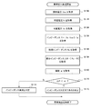
図7は、上述の第1乃至3の実施形態に係る蓄電システム100のインピーダンス異常の検出処理の流れを説明するフローチャートである。本フローチャートにおける判定処理は、電力変換器250を介して、組電池220を充電する際に行われる。特に、車両が停車している状態で、外部電源を介して充電が行われている際に行われる構成とすることが好ましい。
FIG. 7 is a flowchart for explaining the flow of the impedance abnormality detection process of the
図7の異常検出処理が開始されると、組電池220が負荷から切り離され、電圧検出部340が、組電池の開放電圧Vocを取得する(S100)。電力変換器250を介して、組電池220の充電が行われると、電流検出部320は、組電池220へ流れる充電電流Icを取得する(S110)。また、電圧検出部340は、充電電圧Vcを取得する(S120)。演算部382は、取得したデータに基づき、インピーダンスR=|Voc−Vc|/Icを算出する(S130)。演算部382は、予め記憶部384に記憶されている初期インピーダンスRsを取得する(S140)。演算部382は、インピーダンスRと初期インピーダンスRsの差分インピーダンス△R=|Rs−R|を演算する(S150)。演算部382は、予め記憶部384に記憶されている閾値αを取得する(S16
0)。演算部382は、演算した差分インピーダンス△Rと閾値αを比較した結果、差分インピーダンス△Rが閾値αより小さい場合(S170のY)、蓄電システムの電流経路は正常であると判定する(S172)。差分インピーダンス△Rが閾値αより大きい場合(S170のN)、蓄電システムの電流経路には、インピーダンス異常が生じていると判定する(S174)。演算部382は、判定結果を外部へ出力し、異常検出処理を終了する。
When the abnormality detection process of FIG. 7 is started, the assembled
0). As a result of comparing the calculated differential impedance ΔR with the threshold α, the
なお、電力変換器250は、定電流制御で動作するため、通常、S110で取得される充電電流Icは一定となる。そのため、予め電力変換器250の設定電流を記憶部384に記憶させ、記憶部384からデータを取得するように構成することもできる。
In addition, since the
以上、本発明を実施の形態をもとに説明した。実施の形態は例示であり、それらの各構成要素や各処理プロセスの組合せにいろいろな変形例が可能なこと、またそうした変形例も本発明の範囲にあることは当業者に理解されるところである。 The present invention has been described based on the embodiments. The embodiments are exemplifications, and it will be understood by those skilled in the art that various modifications can be made to combinations of the respective constituent elements and processing processes, and such modifications are within the scope of the present invention. .
210 電装バッテリ、220 組電池、250 電力変換器、320 電流検出部、340 電圧検出部、380 異常検出部、382 演算部、384 記憶部、300 電子制御ユニット、390 通信部、254 電解コンデンサ、350 レギュレータ、512 インバータ、EPC 外部充電端子、F 冷却ファン。 210 electric battery, 220 battery pack, 250 power converter, 320 current detection unit, 340 voltage detection unit, 380 abnormality detection unit, 382 calculation unit, 384 storage unit, 300 electronic control unit, 390 communication unit, 254 electrolytic capacitor, 350 Regulator, 512 inverter, EPC external charging terminal, F cooling fan.
Claims (8)
前記組電池の出力電圧より低い出力電圧の電装バッテリと、
前記組電池及び前記電装バッテリを接続する電力変換器であって、前記組電池と前記車両側システムとを接続する電流経路に設けられるノードに接続されている、該電力変換器と、
前記組電池の充放電電流を検出する電流検出部と、
前記組電池の出力電圧を検出する電圧検出部であって、前記電力変換器が接続される前記ノードと前記電力変換器の間に設けられる測定点に接続されている、該電圧検出部と、を備え、
前記電力変換器は、前記電装バッテリの電力を昇圧して前記組電池へ供給すると共に、前記組電池を充電する電流が一定の電流値となる定電流充電で制御される制御モードを有し、
さらに、前記電力変換器が前記制御モードで定電流充電する場合において、前記電力変換器から前記組電池へ流れる充電電流と、前記電圧検出部が検出する電圧に基づいて、前記組電池と前記電力変換器を接続する電流経路のインピーダンスを取得し、該インピーダンスに基づいて前記電流経路の異常検出を行う異常検出部を備えることを特徴とする蓄電システム。 An assembled battery including a plurality of battery cells for supplying electric power to the vehicle-side system;
An electrical battery having an output voltage lower than the output voltage of the assembled battery;
A the battery pack and the power converter connecting the electric battery, the battery pack and the connected to a node provided in a current path that connects the vehicle-side system, and the power converter,
A current detector for detecting a charge / discharge current of the assembled battery;
A voltage detector that detects an output voltage of the battery pack, the voltage detector connected to a measurement point provided between the node to which the power converter is connected and the power converter ; With
The power converter has a control mode in which the electric power of the electric battery is boosted and supplied to the assembled battery, and the current for charging the assembled battery is controlled by constant current charging with a constant current value.
Further, when the power converter performs constant current charging in the control mode, the assembled battery and the power are based on a charging current flowing from the power converter to the assembled battery and a voltage detected by the voltage detection unit. A power storage system comprising: an abnormality detection unit that obtains an impedance of a current path connected to the converter and detects an abnormality of the current path based on the impedance.
前記異常検出部は、
前記電流検出部及び前記電圧検出部の測定結果を用いて前記電流経路のインピーダンスを演算する演算部と、
正常な状態の前記電流経路の初期インピーダンス及び予め設定される閾値を記憶する記憶部と、を含むと共に、
前記電力変換器を介して、前記電装バッテリから前記組電池を充電する場合において前記演算部が演算するインピーダンスの値と、前記記憶部に記憶されている初期インピーダンスとを比較し、前記インピーダンスが前記初期インピーダンスよりも前記閾値以上大きい場合に、前記電流経路がインピーダンス異常であると判断することを特徴とする蓄電システム。 The power storage system according to claim 1,
The abnormality detection unit
A calculation unit that calculates the impedance of the current path using the measurement results of the current detection unit and the voltage detection unit;
A storage unit that stores an initial impedance of the current path in a normal state and a preset threshold value, and
When charging the assembled battery from the electrical battery via the power converter, the impedance value calculated by the calculation unit is compared with the initial impedance stored in the storage unit, and the impedance is A power storage system that determines that the current path is abnormal in impedance when greater than the threshold value by an amount greater than the initial impedance.
さらに、外部電源を接続可能に構成される外部充電端子を備え、
前記電装バッテリは、前記外部充電端子に接続され、
前記電力変換器は、前記電装バッテリが前記外部充電端子に接続される外部電源で充電される際、該電装バッテリの電力を昇圧して前記組電池に供給し、
前記異常検出部は、前記電装バッテリ及び前記組電池が充電される際に、前記異常検出を行うことを特徴とする蓄電システム。 In the electrical storage system of Claim 1 or Claim 2,
In addition, it has an external charging terminal that can be connected to an external power supply,
The electrical battery is connected to the external charging terminal,
When the electric battery is charged by an external power source connected to the external charging terminal, the power converter boosts the electric battery power and supplies it to the assembled battery.
The abnormality detection unit performs the abnormality detection when the electrical battery and the assembled battery are charged.
前記電力変換器は、パルス化した電流で、前記組電池の電力を前記電装バッテリへ供給することを特徴とする蓄電システム。 The power storage system according to claim 3,
The power storage system, wherein the power converter supplies power of the assembled battery to the electric battery with a pulsed current.
さらに、前記外部充電端子の接続状態に応じた信号が入力される通信部を備え、
前記異常検出部は、前記通信部に前記信号が入力された際に、前記異常検出を行うことを特徴とする蓄電システム。 The power storage system according to claim 3,
Furthermore, a communication unit to which a signal according to the connection state of the external charging terminal is input,
The abnormality detection unit performs the abnormality detection when the signal is input to the communication unit.
前記電力変換器は、前記電装バッテリへの出力側に設けられる電解コンデンサを含み、
さらに、前記電流検出部と、前記電圧検出部と、前記異常検出部とを含む電子制御ユニットを備え、
前記電子制御ユニットは、前記電力変換器及び前記電装バッテリから電力が供給されると共に、供給される電力を該電子制御ユニットの駆動電圧に変換するレギュレータを有し、
前記レギュレータは、前記組電池の電力が前記電解コンデンサを介して供給されることを特徴とする蓄電システム。 In the electrical storage system in any one of Claims 1 thru | or 5,
The power converter includes an electrolytic capacitor provided on the output side to the electric battery,
Furthermore, an electronic control unit including the current detection unit, the voltage detection unit, and the abnormality detection unit,
The electronic control unit has a regulator that converts power supplied to the drive voltage of the electronic control unit while being supplied with power from the power converter and the electrical battery.
The power storage system, wherein the regulator is supplied with electric power of the assembled battery via the electrolytic capacitor.
さらに、前記組電池と前記電力変換器とを接続する前記電流経路に設けられ、前記組電池の接続状態を制御する切替部と、
前記切替部を介して前記組電池と接続されるインバータと、を備えることを特徴とする蓄電システム。 The power storage system according to any one of claims 1 to 6,
Further, provided in the current path connecting the assembled battery and the power converter, a switching unit for controlling the connection state of the assembled battery,
An electric storage system comprising: an inverter connected to the assembled battery via the switching unit.
さらに、前記複数の電池セルの内部抵抗を取得する内部抵抗取得部を備え、
前記異常検出部は、前記内部抵抗取得部が取得する前記複数の電池セルの内部抵抗と、前記電流経路のインピーダンスとを用いて、接続不良に起因する接続抵抗異常を検出することを特徴とする蓄電システム。 The power storage system according to claim 1,
Furthermore, an internal resistance acquisition unit that acquires internal resistance of the plurality of battery cells is provided,
The abnormality detection unit detects connection resistance abnormality caused by connection failure using internal resistances of the plurality of battery cells acquired by the internal resistance acquisition unit and impedance of the current path. Power storage system.
Priority Applications (1)
| Application Number | Priority Date | Filing Date | Title |
|---|---|---|---|
| JP2014057466A JP6379552B2 (en) | 2014-03-20 | 2014-03-20 | Power storage system with anomaly detector |
Applications Claiming Priority (1)
| Application Number | Priority Date | Filing Date | Title |
|---|---|---|---|
| JP2014057466A JP6379552B2 (en) | 2014-03-20 | 2014-03-20 | Power storage system with anomaly detector |
Publications (2)
| Publication Number | Publication Date |
|---|---|
| JP2015186266A JP2015186266A (en) | 2015-10-22 |
| JP6379552B2 true JP6379552B2 (en) | 2018-08-29 |
Family
ID=54352302
Family Applications (1)
| Application Number | Title | Priority Date | Filing Date |
|---|---|---|---|
| JP2014057466A Active JP6379552B2 (en) | 2014-03-20 | 2014-03-20 | Power storage system with anomaly detector |
Country Status (1)
| Country | Link |
|---|---|
| JP (1) | JP6379552B2 (en) |
Families Citing this family (12)
| Publication number | Priority date | Publication date | Assignee | Title |
|---|---|---|---|---|
| JP6364396B2 (en) * | 2015-10-27 | 2018-07-25 | 本田技研工業株式会社 | Power storage device, transport device and control method |
| KR101782223B1 (en) * | 2015-10-30 | 2017-09-26 | 주식회사 포스코아이씨티 | Apparatus for Diagnosing Battery Conditioning System, Energy Storage System including That Apparatus |
| CN105676143A (en) * | 2016-02-01 | 2016-06-15 | 哈尔滨工业大学 | Storage battery factory parameter online detection device |
| JP6776889B2 (en) * | 2016-12-27 | 2020-10-28 | 株式会社ダイフク | Transport trolley |
| KR20180090145A (en) | 2017-02-02 | 2018-08-10 | 삼성에스디아이 주식회사 | Battery management system and batterm management method |
| DE102018214612A1 (en) * | 2018-08-29 | 2020-03-05 | Robert Bosch Gmbh | Method for detecting contact errors in a battery pack and system for carrying out the method |
| CN112654877B (en) * | 2018-11-15 | 2024-06-04 | 深圳市欢太科技有限公司 | Charging detection method, charging detection device and terminal equipment |
| KR102819970B1 (en) * | 2019-05-03 | 2025-06-13 | 주식회사 엘지에너지솔루션 | Apparatus and method for diagnosing battery cell |
| KR102745196B1 (en) * | 2019-07-22 | 2024-12-23 | 주식회사 엘지에너지솔루션 | Apparatus and method for diagnosing battery resistance |
| GB2592243B (en) * | 2020-02-21 | 2024-06-12 | Dyson Technology Ltd | Battery system |
| CN113284332B (en) * | 2021-04-16 | 2022-09-02 | 矿冶科技集团有限公司 | Mining wireless sensing terminal |
| EP4510414A4 (en) * | 2022-05-19 | 2025-06-04 | Contemporary Amperex Technology (Hong Kong) Limited | Detection method and energy storage system |
Family Cites Families (3)
| Publication number | Priority date | Publication date | Assignee | Title |
|---|---|---|---|---|
| JP3685105B2 (en) * | 2001-08-08 | 2005-08-17 | 日産自動車株式会社 | Apparatus and method for calculating output deterioration of secondary battery |
| JP4163097B2 (en) * | 2003-11-28 | 2008-10-08 | 本田技研工業株式会社 | VEHICLE POWER STORAGE DEVICE AND HIGH-PIEZOELECTRIC COOLING DEVICE FOR VEHICLE MOTOR |
| JP5453232B2 (en) * | 2010-12-24 | 2014-03-26 | 本田技研工業株式会社 | Electric vehicle |
-
2014
- 2014-03-20 JP JP2014057466A patent/JP6379552B2/en active Active
Also Published As
| Publication number | Publication date |
|---|---|
| JP2015186266A (en) | 2015-10-22 |
Similar Documents
| Publication | Publication Date | Title |
|---|---|---|
| JP6379552B2 (en) | Power storage system with anomaly detector | |
| US9758044B2 (en) | Bus leakage resistance estimation for electrical isolation testing and diagnostics | |
| KR101473397B1 (en) | Apparatus and method for checking current sensor abnormality in battery pack | |
| US9096134B2 (en) | Enhanced HV pre-charge heater diagnostic detection system for liquid cooled HV battery packs | |
| JP4572850B2 (en) | Power control device | |
| US12539781B2 (en) | Management device and power supply system | |
| US20190123568A1 (en) | Power Supply System | |
| JPWO2018056263A1 (en) | Power supply system | |
| JP6504855B2 (en) | Deterioration detection device and deterioration detection method | |
| KR20160036423A (en) | Apparatus and method for controlling high voltage battery in vehicle | |
| JP6853797B2 (en) | Battery monitoring device and relay status diagnostic method | |
| JP6412847B2 (en) | Power storage device and control method | |
| KR20180023140A (en) | Power Relay Assembly fault controlling system and the method thereof | |
| US11411259B2 (en) | Battery control unit | |
| JP2017173264A (en) | Method and device for specifying deterioration | |
| CN113016099B (en) | Battery control device | |
| CN107402352A (en) | Diagnostic method, the operation method of cell apparatus, the operation method of equipment and equipment | |
| JP7380411B2 (en) | battery monitoring device | |
| JP2020046334A (en) | Battery monitoring device | |
| JP2016161352A (en) | Degradation detection apparatus and degradation detection method | |
| JP5768613B2 (en) | Power storage device abnormality detection circuit and power storage device abnormality detection method | |
| EP4102245B1 (en) | Battery apparatus and current sensor diagnosis method | |
| KR102839450B1 (en) | Battery apparatus and drift fault diagnosis method | |
| KR102876312B1 (en) | Battery apparatus, battery management system, and method of measuring precharge current | |
| JP6040916B2 (en) | Disconnection detector |
Legal Events
| Date | Code | Title | Description |
|---|---|---|---|
| A621 | Written request for application examination |
Free format text: JAPANESE INTERMEDIATE CODE: A621 Effective date: 20170111 |
|
| RD01 | Notification of change of attorney |
Free format text: JAPANESE INTERMEDIATE CODE: A7421 Effective date: 20170419 |
|
| A977 | Report on retrieval |
Free format text: JAPANESE INTERMEDIATE CODE: A971007 Effective date: 20171030 |
|
| A131 | Notification of reasons for refusal |
Free format text: JAPANESE INTERMEDIATE CODE: A131 Effective date: 20171107 |
|
| A521 | Request for written amendment filed |
Free format text: JAPANESE INTERMEDIATE CODE: A523 Effective date: 20171226 |
|
| A131 | Notification of reasons for refusal |
Free format text: JAPANESE INTERMEDIATE CODE: A131 Effective date: 20180424 |
|
| A521 | Request for written amendment filed |
Free format text: JAPANESE INTERMEDIATE CODE: A523 Effective date: 20180620 |
|
| TRDD | Decision of grant or rejection written | ||
| A01 | Written decision to grant a patent or to grant a registration (utility model) |
Free format text: JAPANESE INTERMEDIATE CODE: A01 Effective date: 20180703 |
|
| A61 | First payment of annual fees (during grant procedure) |
Free format text: JAPANESE INTERMEDIATE CODE: A61 Effective date: 20180716 |
|
| R151 | Written notification of patent or utility model registration |
Ref document number: 6379552 Country of ref document: JP Free format text: JAPANESE INTERMEDIATE CODE: R151 |