JP6378504B2 - Sheet processing apparatus and control method and program thereof - Google Patents

Sheet processing apparatus and control method and program thereof Download PDF

Info

Publication number
JP6378504B2
JP6378504B2 JP2014046756A JP2014046756A JP6378504B2 JP 6378504 B2 JP6378504 B2 JP 6378504B2 JP 2014046756 A JP2014046756 A JP 2014046756A JP 2014046756 A JP2014046756 A JP 2014046756A JP 6378504 B2 JP6378504 B2 JP 6378504B2
Authority
JP
Japan
Prior art keywords
crease
sheet
cover
processing
unit
Prior art date
Legal status (The legal status is an assumption and is not a legal conclusion. Google has not performed a legal analysis and makes no representation as to the accuracy of the status listed.)
Active
Application number
JP2014046756A
Other languages
Japanese (ja)
Other versions
JP2015168233A5 (en
JP2015168233A (en
Inventor
宗隆 坂田
宗隆 坂田
Current Assignee (The listed assignees may be inaccurate. Google has not performed a legal analysis and makes no representation or warranty as to the accuracy of the list.)
Canon Inc
Original Assignee
Canon Inc
Priority date (The priority date is an assumption and is not a legal conclusion. Google has not performed a legal analysis and makes no representation as to the accuracy of the date listed.)
Filing date
Publication date
Application filed by Canon Inc filed Critical Canon Inc
Priority to JP2014046756A priority Critical patent/JP6378504B2/en
Priority to US14/635,256 priority patent/US10011138B2/en
Publication of JP2015168233A publication Critical patent/JP2015168233A/en
Publication of JP2015168233A5 publication Critical patent/JP2015168233A5/ja
Application granted granted Critical
Publication of JP6378504B2 publication Critical patent/JP6378504B2/en
Active legal-status Critical Current
Anticipated expiration legal-status Critical

Links

Images

Classifications

    • BPERFORMING OPERATIONS; TRANSPORTING
    • B42BOOKBINDING; ALBUMS; FILES; SPECIAL PRINTED MATTER
    • B42CBOOKBINDING
    • B42C7/00Manufacturing bookbinding cases or covers of books or loose-leaf binders
    • B42C7/005Creasing the back of covers
    • GPHYSICS
    • G03PHOTOGRAPHY; CINEMATOGRAPHY; ANALOGOUS TECHNIQUES USING WAVES OTHER THAN OPTICAL WAVES; ELECTROGRAPHY; HOLOGRAPHY
    • G03GELECTROGRAPHY; ELECTROPHOTOGRAPHY; MAGNETOGRAPHY
    • G03G15/00Apparatus for electrographic processes using a charge pattern
    • G03G15/65Apparatus which relate to the handling of copy material
    • G03G15/6538Devices for collating sheet copy material, e.g. sorters, control, copies in staples form
    • G03G15/6541Binding sets of sheets, e.g. by stapling, glueing
    • G03G15/6544Details about the binding means or procedure
    • GPHYSICS
    • G03PHOTOGRAPHY; CINEMATOGRAPHY; ANALOGOUS TECHNIQUES USING WAVES OTHER THAN OPTICAL WAVES; ELECTROGRAPHY; HOLOGRAPHY
    • G03GELECTROGRAPHY; ELECTROPHOTOGRAPHY; MAGNETOGRAPHY
    • G03G2215/00Apparatus for electrophotographic processes
    • G03G2215/00362Apparatus for electrophotographic processes relating to the copy medium handling
    • G03G2215/00789Adding properties or qualities to the copy medium
    • G03G2215/00877Folding device
    • GPHYSICS
    • G03PHOTOGRAPHY; CINEMATOGRAPHY; ANALOGOUS TECHNIQUES USING WAVES OTHER THAN OPTICAL WAVES; ELECTROGRAPHY; HOLOGRAPHY
    • G03GELECTROGRAPHY; ELECTROPHOTOGRAPHY; MAGNETOGRAPHY
    • G03G2215/00Apparatus for electrophotographic processes
    • G03G2215/00362Apparatus for electrophotographic processes relating to the copy medium handling
    • G03G2215/00919Special copy medium handling apparatus
    • G03G2215/00936Bookbinding

Description

本発明は、シート処理装置及びその制御方法とプログラムに関する。   The present invention relates to a sheet processing apparatus, a control method therefor, and a program.

近年、デジタル複写機や複合機等の画像形成装置を使用して、くるみ製本などの製本を行う印刷物にクリース(筋付け)処理を施すケースが増えている。クリース(筋付け)とは、印刷用紙(以後、メディア)に対して、折り処理を施す前に、折り筋を入れる処理である。例えば、くるみ製本の場合、くるみ製本の背の角にクリースを施す場合がある。そうすることで背の角の折り目が綺麗になり、製本された成果物(製本物)の品位を高めることができる。   In recent years, there has been an increasing number of cases in which crease processing is performed on printed matter such as case binding using an image forming apparatus such as a digital copying machine or a multifunction peripheral. The crease is a process for putting a crease before performing a fold process on a printing paper (hereinafter, media). For example, in case binding, crease may be applied to the back corner of case binding. By doing so, the folds at the back corners become beautiful, and the quality of the bound product (bookbinding product) can be improved.

またクリースは、利用者に折り込みを入れて欲しい位置に、予め、折り筋を付ける用途でも利用される。例えば、くるみ製本の場合、表紙に紙厚の大きいメディアを利用することが多い。そのため、予め、表紙に折り筋を付けておくことで、利用者が表紙を開きやすくなる利点がある。更にくるみ製本では、表紙と中紙を糊付けしているため、表紙を開いたときに糊付け位置に力が加わってしまい、表紙が剥がれ易くなることがあった。そこで、クリースを糊付け位置から離れた場所に入れることで、利用者が表紙を開いても、糊付け位置に負荷がかからないため、表紙が剥がれ易くなるのを防止できる利点がある。以後、上記のような、利用者に折り込みを入れて欲しい位置に施すクリースを、折り返し用クリースと表記する。   The crease is also used for applying a crease in advance to a position where the user wants to fold. For example, in case binding, a medium having a large paper thickness is often used for the cover. Therefore, there is an advantage that the user can easily open the cover by making a crease in the cover beforehand. Further, in case binding, since the cover and the inner sheet are glued, a force is applied to the glue position when the cover is opened, and the cover may be easily peeled off. Therefore, by putting the crease away from the gluing position, there is an advantage that even if the user opens the cover, no load is applied to the gluing position, so that it is possible to prevent the cover from being easily peeled off. Hereinafter, the crease applied to the position that the user wants to fold is referred to as “folding crease”.

折り返し用クリースは、利用者の利便性を考慮して、その位置を決定すべきである。例えば、くるみ製本の背の角と折り返し用クリースの位置とが近すぎると、利用者は、そのくるみ製本された本を手に取ったときに表紙を開きにくい。また、くるみ製本の背の角と折り返し用クリースの位置とがあまり離れていると、その本の1ページ目の内容と、折り返し用クリースの位置とが重なり、そのページの内容が見にくいものとなる。つまり、折り返し用クリースの位置は、くるみ製本毎に決定すべきものであり、固定の位置に折り返し用クリースを施せば良いというものではない。   The position of the folding crease should be determined in consideration of user convenience. For example, if the back corner of the case binding and the position of the folding crease are too close, it is difficult for the user to open the cover when picking up the case bound book. Also, if the back corner of the case binding is far away from the position of the folding crease, the contents of the first page of the book overlap with the position of the folding crease, making it difficult to see the contents of the page. . That is, the position of the folding crease should be determined for each case binding, and the folding crease should not be provided at a fixed position.

また、通常、クリース位置は、メディアの端を基準位置として、その基準位置から所定長離れた位置というように指定する必要がある。それは、クリーサ装置が用紙の先端を検知し、その先端位置から、指示された長さの位置にクリース処理を施すように構成されているためである。   Also, normally, the crease position needs to be specified as a position that is a predetermined distance away from the reference position with the end of the medium as the reference position. This is because the creaser device is configured to detect the leading edge of the paper and perform a crease process from the leading edge position to a position of the instructed length.

折り返し用クリースの位置を指定する方法が、例えば特許文献1に記載されている。この方法を用いると、くるみ製本の表紙に対して、オペレータが指定した位置に、かつ、オペレータが指定した数の折り返し用クリースを施すことができる。   A method for designating the position of the folding crease is described in Patent Document 1, for example. Using this method, the folding crease can be applied to the cover of the case binding at the position designated by the operator and the number designated by the operator.

特開2013−119451号公報JP2013-119451A

上記特許文献1に記載の方法では、オペレータが指定した位置と指定した数とに従って折り返し用クリースを施すことができるが、オペレータ自身が、メディアの長さを把握し、折り返しクリースの位置を決定する必要がある。しかしながら、通常、折り返し用クリースの位置は、背表紙の角からの長さを基準に考えることが多い。そのため、特許文献1の方法を用いると、オペレータは、メディアの長さを把握して、折り返し用クリースの位置を計算して決定しなければならず面倒であった。   In the method described in Patent Document 1, the crease crease can be applied according to the position designated by the operator and the designated number, but the operator himself grasps the length of the medium and determines the position of the crease crease. There is a need. However, the position of the folding crease is usually considered based on the length from the corner of the spine. Therefore, using the method of Patent Document 1, it is troublesome for the operator to grasp the length of the medium and calculate and determine the position of the folding crease.

本発明の目的は、上記従来技術の問題点を解決することにある。   An object of the present invention is to solve the above-mentioned problems of the prior art.

本発明の特徴は、製本物における折り返し用のクリース位置を容易に指定できるようにする技術を提供することにある。   A feature of the present invention is to provide a technique that makes it possible to easily specify a crease position for folding in a bookbinding product.

上記目的を達成するために本発明の一態様に係るシート処理装置は、シートに画像を形成する画像形成手段と、前記画像形成手段から搬送されたシートに対してクリース処理を行うクリース処理手段と、前記クリース処理手段によりクリース処理が行われた表紙用のシートに、前記クリース処理手段によりクリース処理が行われずに前記画像形成手段から搬送された中紙用のシートを糊付けして、製本物を生成するくるみ製本手段と、少なくとも(i)前記表紙用のシートのサイズ、(ii)前記製本物の背表紙の厚み、及び(iii)前記背表紙の角からの長さであるオフセット値、に基づいて、前記表紙用のシートに対するクリース位置を決定し、前記表紙用のシートに対して、前記決定したクリース位置にクリース処理を行うよう前記クリース処理手段を制御する制御手段と、を有し、(ii)前記背表紙の厚みは、前記表紙用のシートの種類、前記中紙用のシートの種類、及び前記中紙用のシートの枚数に基づいて決定され、(iii)前記オフセット値は、ユーザ指示に従って入力された値である、ことを特徴とする。 In order to achieve the above object, a sheet processing apparatus according to an aspect of the present invention includes an image forming unit that forms an image on a sheet, and a crease processing unit that performs a crease process on the sheet conveyed from the image forming unit. The cover sheet subjected to the crease processing by the crease processing means is glued with the intermediate sheet conveyed from the image forming means without being creased by the crease processing means. The case binding means to be generated, and at least (i) the size of the cover sheet, (ii) the thickness of the bookbinding spine cover, and (iii) the offset value that is the length from the corner of the spine cover, And determining a crease position with respect to the cover sheet, and performing the crease process on the cover sheet at the determined crease position. And (ii) the thickness of the spine cover is determined by the type of the cover sheet, the type of the intermediate sheet, and the number of sheets for the intermediate sheet. (Iii) The offset value is a value input in accordance with a user instruction .

本発明によれば、製本物における折り返し用のクリース位置を容易に指定できるという効果がある。   According to the present invention, there is an effect that a crease position for folding in a bookbinding product can be easily specified.

本発明のその他の特徴及び利点は、添付図面を参照とした以下の説明により明らかになるであろう。尚、添付図面においては、同じ若しくは同様の構成には、同じ参照番号を付す。   Other features and advantages of the present invention will become apparent from the following description with reference to the accompanying drawings. In the accompanying drawings, the same or similar components are denoted by the same reference numerals.

添付図面は明細書に含まれ、その一部を構成し、本発明の実施の形態を示し、その記述と共に本発明の原理を説明するために用いられる。
本実施形態に係るシート処理システムの構成を示す図。 実施形態に係る画像形成装置の構成を示す図。 実施形態に係る給紙装置の断面図。 実施形態に係る画像形成装置本体の断面図。 実施形態に係るクリーサ装置の断面図。 実施形態に係るくるみ製本機の断面図。 実施形態に係るフィニッシャ装置の断面図。 実施形態に係る画像形成装置のハードウェア構成を説明するブロック図。 実施形態に係るクリーサ制御部の詳細な構成を示すブロック図。 実施形態に係る画像処理装置のハードウェア構成を説明するブロック図。 実施形態に係る画像形成装置と画像処理装置のソフトウェア構成を説明するブロック図。 実施形態に係る画像処理装置の表示部に表示されるジョブ設定画面の一例を示す図。 実施形態に係る画像形成装置の操作パネルに表示される、くるみ製本時の折り返し設定画面の一例を示す図。 実施形態におけるくるみ製本に関する、背表紙の角と折り返しの位置関係を説明する図(A)(B)と、背表紙の厚みと折り返しの位置とクリース位置との関係を示す図(C)。 本発明の実施形態1,3に係る画像形成装置におけるクリース処理を説明するフローチャート。 実施形態2に係る中綴じ製本に関する、背の角と折り返しの位置関係を説明する図(A)(B)と、背の角と折り返しの位置とクリース位置との関係を示す図(C)。 実施形態2に係る画像形成装置の操作パネルに表示される、中綴じ製本時の折り返し設定画面の一例を示す図。 実施形態2に係る画像処理装置の表示部に表示されるジョブ設定画面の一例を示す図。 本発明の実施形態2,4に係る画像形成装置で中綴じ製本を実行する際のクリース処理を説明するフローチャート。 本実施形態3で形成される、左綴じのくるみ製本と右綴じのくるみ製本を説明する図(A)(B)と、クリース位置1とクリース位置2を説明する図(C)。 実施形態4で形成される左綴じの中綴じ製本と、右綴じの中綴じ製本を説明する図(A)(B)と、フィニッシャ装置における、中綴じ製本の形成プロセスを示す図(C)と、中綴じ製本表紙に対するクリース位置1とクリース位置2を説明する図(D)。 本発明の実施形態5に係る画像処理装置の表示部に表示される確認メッセージ画面の一例を示す図。 実施形態5に係る画像処理装置による、本文1ページ目の絵が隠れる場合の警告処理の手順を説明するフローチャート。 実施形態7に係るくるみ製本の糊付け部分(A)と、警告メッセージ画面の一例を示す図(B)。
The accompanying drawings are included in the specification, constitute a part thereof, show an embodiment of the present invention, and are used to explain the principle of the present invention together with the description.
1 is a diagram illustrating a configuration of a sheet processing system according to an embodiment. 1 is a diagram illustrating a configuration of an image forming apparatus according to an embodiment. FIG. 3 is a cross-sectional view of the sheet feeding device according to the embodiment. 1 is a cross-sectional view of an image forming apparatus main body according to an embodiment. Sectional drawing of the creaser apparatus which concerns on embodiment. Sectional drawing of the case binding machine which concerns on embodiment. Sectional drawing of the finisher apparatus which concerns on embodiment. FIG. 2 is a block diagram illustrating a hardware configuration of the image forming apparatus according to the embodiment. The block diagram which shows the detailed structure of the crease control part which concerns on embodiment. FIG. 2 is a block diagram illustrating a hardware configuration of the image processing apparatus according to the embodiment. FIG. 2 is a block diagram for explaining a software configuration of the image forming apparatus and the image processing apparatus according to the embodiment. FIG. 4 is a diagram illustrating an example of a job setting screen displayed on the display unit of the image processing apparatus according to the embodiment. 6 is a diagram showing an example of a folding setting screen at the time of case binding displayed on the operation panel of the image forming apparatus according to the embodiment. FIG. The figure (A) (B) explaining the positional relationship of the corner | angular of a spine cover and folding | turnback regarding the case binding in embodiment, and the figure (C) which shows the relationship between the thickness of a spine cover, the position of folding | wrapping, and a crease position. 9 is a flowchart for explaining crease processing in the image forming apparatus according to the first and third embodiments of the present invention. The figure (A) (B) explaining the positional relationship of a back corner | angular and folding | turnback regarding the saddle stitch bookbinding which concerns on Embodiment 2, and the figure (C) which shows the relationship between a back corner | angular, folding | turning position, and a crease position. FIG. 10 is a diagram illustrating an example of a folding setting screen for saddle stitch binding displayed on the operation panel of the image forming apparatus according to the second embodiment. FIG. 9 is a diagram illustrating an example of a job setting screen displayed on a display unit of an image processing apparatus according to a second embodiment. 9 is a flowchart for explaining crease processing when performing saddle stitch binding in the image forming apparatus according to Embodiments 2 and 4 of the present invention. FIGS. 4A and 4B are diagrams illustrating left-bound case binding and right-bound case binding formed in the third embodiment, and FIGS. 3C and 3C are diagrams illustrating crease position 1 and crease position 2. FIGS. 7A and 7B are diagrams for explaining left-bound saddle-stitched bookbinding, right-bound saddle-stitched bookbinding formed in the fourth embodiment, and FIG. 8C is a diagram illustrating a saddle-stitched bookbinding process in the finisher apparatus. FIG. 4D is a diagram for explaining the crease position 1 and the crease position 2 with respect to the saddle stitch bookbinding cover. The figure which shows an example of the confirmation message screen displayed on the display part of the image processing apparatus which concerns on Embodiment 5 of this invention. 10 is a flowchart for explaining a procedure of warning processing when the image of the first page of the text is hidden by the image processing apparatus according to the fifth embodiment. The figure which shows an example of the glue part (A) of the case binding which concerns on Embodiment 7, and a warning message screen.

以下、添付図面を参照して本発明の実施形態を詳しく説明する。尚、以下の実施形態は特許請求の範囲に係る本発明を限定するものでなく、また本実施形態で説明されている特徴の組み合わせの全てが本発明の解決手段に必須のものとは限らない。   Hereinafter, embodiments of the present invention will be described in detail with reference to the accompanying drawings. The following embodiments do not limit the present invention according to the claims, and all combinations of features described in the embodiments are not necessarily essential to the solution means of the present invention. .

図1は、本実施形態に係るシート処理システムの構成を示す図である。   FIG. 1 is a diagram illustrating a configuration of a sheet processing system according to the present embodiment.

シート処理システムは、画像形成装置101、画像処理装置102、及びこれらを接続するネットワーク103を有する。画像処理装置102は、オペレータが操作して印刷ジョブの作成等の処理を行うのに使用され、ジョブの管理、及びRIPや面付けなどの処理を行い、処理済の画像データを画像形成装置101に送信して印刷させる。   The sheet processing system includes an image forming apparatus 101, an image processing apparatus 102, and a network 103 that connects them. The image processing apparatus 102 is used by an operator to perform processing such as creation of a print job. The image processing apparatus 102 performs job management, processing such as RIP and imposition, and processes the processed image data. Send to and print.

図2は、実施形態に係る画像形成装置101の構成を示す図である。   FIG. 2 is a diagram illustrating a configuration of the image forming apparatus 101 according to the embodiment.

この画像形成装置101は、外部に設けられた給紙装置201,202、画像形成装置本体203、クリーサ装置204、くるみ製本機205、フィニッシャ装置206を備えている。画像形成装置本体203は、上流側の画像形成部210と、下流側の定着・スキャナ部211を備える。   The image forming apparatus 101 includes external sheet feeding apparatuses 201 and 202, an image forming apparatus main body 203, a creaser apparatus 204, a case binding machine 205, and a finisher apparatus 206. The image forming apparatus main body 203 includes an upstream image forming unit 210 and a downstream fixing / scanner unit 211.

外部給紙装置201,202は、大量のメディアを画像形成装置本体203に供給できる大容量の給紙装置である。画像形成装置本体203は印刷装置であり、外部給紙装置201,202、或いは画像形成装置本体203に内蔵された給紙トレイから給紙したメディアに印刷を行う。クリーサ装置204は、メディアにクリースを施す。くるみ製本機205は、くるみ製本を行う。フィニッシャ装置205は、パンチやステイプルなどのフィニッシング処理や、中綴じ製本を実行できる。   The external paper feeders 201 and 202 are large-capacity paper feeders that can supply a large amount of media to the image forming apparatus main body 203. The image forming apparatus main body 203 is a printing apparatus, and performs printing on media fed from the external paper feeding apparatuses 201 and 202 or a paper feed tray built in the image forming apparatus main body 203. The creaser 204 applies crease to the media. The case binding machine 205 performs case binding. The finisher device 205 can execute finishing processing such as punching and stapling and saddle stitch binding.

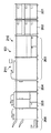
図3は、実施形態に係る給紙装置201の断面図である。尚、給紙装置202の構成も同様であるため、その説明を省略する。   FIG. 3 is a cross-sectional view of the paper feeding device 201 according to the embodiment. Note that the configuration of the sheet feeding device 202 is the same, and thus the description thereof is omitted.

ストレートパス307は、給紙トレイ301、給紙トレイ302、給紙トレイ303、又は上流側から搬送されてきたメディアを下流側の装置へ搬送するパスである。本実施形態では、外部給紙装置202の上流側に外部給紙装置201、下流側に画像形成装置本体203が配置されている。そのため外部給紙装置202は、ストレートパス307を通じて、給紙トレイ301〜303に収容されているメディア、或いは外部給紙装置201から搬送されてきたメディアを画像形成装置本体203へ搬送する。給紙トレイ301〜303は、メディアを給紙するトレイである。各給紙トレイは、リフトアップモータ(不図示)により給紙トレイ下部をリフトアップすることで、収容しているメディアを、各対応する給紙ローラ304〜306に接触させることができる。給紙ローラ304〜306のそれぞれは、各対応する給紙トレイ301,302,303に収容されているメディアを1枚ずつ引き出すローラで、これらローラの回転により引き出されたメディアはストレートパス307に送られて搬送される。   The straight path 307 is a path for transporting the media fed from the paper feed tray 301, the paper feed tray 302, the paper feed tray 303, or the upstream side to the downstream apparatus. In the present exemplary embodiment, an external sheet feeder 201 is disposed on the upstream side of the external sheet feeder 202, and an image forming apparatus main body 203 is disposed on the downstream side. Therefore, the external sheet feeder 202 conveys the media stored in the sheet feed trays 301 to 303 or the medium conveyed from the external sheet feeder 201 to the image forming apparatus main body 203 through the straight path 307. The paper feed trays 301 to 303 are trays for feeding media. Each of the paper feed trays can lift the lower portion of the paper feed tray by a lift-up motor (not shown), thereby bringing the contained media into contact with the corresponding paper feed rollers 304 to 306. Each of the paper feed rollers 304 to 306 is a roller that pulls out the media stored in the corresponding paper feed trays 301, 302, and 303 one by one, and the media drawn by the rotation of these rollers is sent to the straight path 307. To be transported.

図4(A)、図4(B)は、画像形成装置本体203の断面図である。   4A and 4B are cross-sectional views of the image forming apparatus main body 203. FIG.

図4(A)は、画像形成装置本体203の上流側の画像形成部210の構造を示し、図4(B)は、画像形成装置本体203の下流側の定着・スキャナ部211の構成を示す。ここで、上流側の画像形成部210は外部給紙装置202と接続され、下流側の定着・スキャナ部211はクリーサ装置204と接続されている。   4A shows the structure of the image forming unit 210 on the upstream side of the image forming apparatus main body 203, and FIG. 4B shows the configuration of the fixing / scanner unit 211 on the downstream side of the image forming apparatus main body 203. . Here, the upstream image forming unit 210 is connected to the external paper feeding device 202, and the downstream fixing / scanner unit 211 is connected to the crease device 204.

給紙トレイ401、給紙トレイ402は、メディアを収容して給紙するトレイである。リフトアップモータ(不図示)により給紙トレイの下部をリフトアップすることで、収容されているメディアを給紙ローラ403、或いは給紙ローラ404に接触させることができる。給紙ローラ403、給紙ローラ404は、それぞれ、給紙トレイ401、給紙トレイ402に収容されているメディアを1枚ずつ引き出すローラである。給紙トレイ401,402に収容されているメディアは、それぞれ、給紙ローラ403,404の回転により搬送経路に送り出されて搬送パス411まで搬送される。搬送パス412は、二次転写位置410までメディアを搬送するパスである。また搬送パス412は、外部給紙装置202のストレートパスと接続されている。これにより、搬送パス412には、搬送パス411から搬送されてきたメディア、及び、外部給紙装置202のストレートパス307を搬送されてきたメディアが搬送される。   A paper feed tray 401 and a paper feed tray 402 are trays that accommodate and feed media. By lifting up the lower portion of the paper feed tray by a lift-up motor (not shown), the accommodated media can be brought into contact with the paper feed roller 403 or the paper feed roller 404. The paper feed roller 403 and the paper feed roller 404 are rollers for pulling out the media stored in the paper feed tray 401 and the paper feed tray 402 one by one, respectively. The media stored in the paper feed trays 401 and 402 are sent to the transport path by the rotation of the paper feed rollers 403 and 404, and are transported to the transport path 411. The conveyance path 412 is a path for conveying the medium to the secondary transfer position 410. The conveyance path 412 is connected to the straight path of the external sheet feeder 202. As a result, the medium conveyed from the conveyance path 411 and the medium conveyed through the straight path 307 of the external sheet feeder 202 are conveyed to the conveyance path 412.

現像ユニット405〜408はそれぞれ、画像を形成するための現像ユニットであり、Y、M、C、Kの4色のステーションを具備している。ここで形成された画像は、図中、時計回りに回転している中間転写ベルト409に一次転写され、二次転写位置410で搬送パス412上を搬送されてきたメディアに転写される。こうして画像が転写されたメディアは、搬送パス412を通じて第一定着部413まで搬送される。第一定着部413では、画像が転写されたメディアに対して加熱、加圧を施すことにより、転写された画像をメディアに定着させる。   Each of the developing units 405 to 408 is a developing unit for forming an image, and includes four color stations of Y, M, C, and K. The image formed here is primarily transferred to an intermediate transfer belt 409 rotating clockwise in the drawing, and transferred to a medium conveyed on a conveyance path 412 at a secondary transfer position 410. The medium on which the image is transferred in this manner is conveyed to the first fixing unit 413 through the conveyance path 412. The first fixing unit 413 fixes the transferred image on the medium by applying heat and pressure to the medium on which the image has been transferred.

フラッパ415は、第一定着部413を通過したメディアを、搬送パス416もしくは搬送パス417に振り分ける。フラッパ415は、揺動軸を中心に揺動可能に構成され、メディアの搬送方向を規定する。フラッパ415が、図中時計回りの方向に揺動しているときは、メディアは搬送パス417に搬送され、図中反時計回りの方向に揺動しているときは、メディアは搬送パス416に搬送される。第一定着部413を通過したメディアが、搬送パス416、もしくは搬送パス417のどちらを搬送されるかは、メディアの種類(坪量が大きいなど)などの条件によって決定される。そのメディアに対して再度、定着が必要だと判断した場合は、メディアは、搬送パス417に搬送され、再度定着が不要と判断した場合は、メディアは、搬送パス416に搬送される。第二定着部414は、搬送パス417上を搬送されてきたメディアに対して、再度、加熱、加圧を施すための装置である。   The flapper 415 distributes the media that has passed through the first fixing unit 413 to the transport path 416 or the transport path 417. The flapper 415 is configured to be swingable about a swing shaft, and defines the media transport direction. When the flapper 415 swings in the clockwise direction in the figure, the media is transported to the transport path 417. When the flapper 415 swings in the counterclockwise direction in the figure, the media enters the transport path 416. Be transported. Whether the medium that has passed through the first fixing unit 413 is conveyed through the conveyance path 416 or the conveyance path 417 is determined by conditions such as the type of medium (such as a large basis weight). If it is determined that fixing is necessary for the medium again, the medium is transported to the transport path 417, and if it is determined that fixing is not necessary again, the media is transported to the transport path 416. The second fixing unit 414 is a device for again applying heat and pressure to the medium conveyed on the conveyance path 417.

排紙フラッパ418は、搬送パス416、もしくは搬送パス417から搬送されてきたメディアを、クリーサ装置204、もしくは搬送パス419に搬送するために使われる。排紙フラッパ418は、揺動軸を中心に揺動可能に構成され、メディアの搬送方向を規定する。排紙フラッパ418が、図中時計回りの方向に揺動しているときは、メディアはクリーサ装置204に搬送され、図中反時計回りの方向に揺動しているときは、メディアは搬送パス419に搬送される。搬送パス419を搬送されたメディアは、反転パス420に搬送される。そして、スイッチバック処理により、メディアの搬送方向が180度変更される。フラッパ421は、揺動軸を中心に揺動可能に構成され、メディアの搬送方向を規定する。フラッパ421が、図中時計回りの方向に揺動されると、反転パス420から搬送されてきたメディアは、搬送パス422に搬送される。搬送パス422は、図4(A)の搬送パス411へ通じている。こうして反転パス420で反転されたメディアは、印刷面が表裏逆転して二次転写位置410に送られる。この仕組みにより、画像形成装置本体203は両面印刷を実施することができる。   The paper discharge flapper 418 is used for transporting the media transported from the transport path 416 or the transport path 417 to the cleaner device 204 or the transport path 419. The paper discharge flapper 418 is configured to be swingable about a swing shaft, and defines a medium transport direction. When the paper discharge flapper 418 is swung in the clockwise direction in the figure, the medium is conveyed to the crease device 204, and when the paper discharge flapper 418 is swung in the counterclockwise direction in the figure, the medium is in the conveyance path. It is conveyed to 419. The medium that has been transported through the transport path 419 is transported to the reverse path 420. Then, the media transport direction is changed by 180 degrees by the switchback process. The flapper 421 is configured to be swingable about a swing shaft, and defines the media transport direction. When the flapper 421 is swung in the clockwise direction in the drawing, the medium conveyed from the reverse path 420 is conveyed to the conveyance path 422. The conveyance path 422 leads to the conveyance path 411 in FIG. The media reversed in the reversing path 420 is sent to the secondary transfer position 410 with the printing surface reversed. With this mechanism, the image forming apparatus main body 203 can perform double-sided printing.

フラッパ421が図中反時計回り方向に揺動された場合は、メディアは搬送パス419を通過する。そして、排紙フラッパ418が、図中反時計回り方向に揺動されていると、メディアはクリーサ装置204に搬送される。つまり反転パス420でメディアを反転しているので、定着画像を下向きにした状態で、メディアをクリーサ装置204に搬送可能となる。尚、定着画像を上向きにした状態で、メディアをクリーサ装置204に搬送する場合は、反転パス420を使わないことで実現できる。   When the flapper 421 is swung in the counterclockwise direction in the drawing, the medium passes through the transport path 419. When the paper discharge flapper 418 is swung in the counterclockwise direction in the drawing, the medium is conveyed to the creaser device 204. That is, since the medium is reversed in the reversing path 420, the medium can be conveyed to the crease device 204 with the fixed image facing downward. In the case where the medium is transported to the cleaner device 204 with the fixed image facing upward, it can be realized by not using the reverse path 420.

自動原稿搬送装置(ADF)423は、原稿トレイの積載面にセットされた原稿束を1頁目の原稿から、ページ順に、順番に分離して、スキャナ424によって原稿走査させるドキュメントフィーダである。スキャナ424は、自動原稿搬送装置423から搬送された原稿に光源(不図示)を照射し、CCD(不図示)にて原稿画像を走査し、その原稿の画像データを生成する。こうして生成された画像データは画像処理が施され、現像ユニット405〜408により、その画像がメディアに転写される。こうして、コピー動作が実施される。   An automatic document feeder (ADF) 423 is a document feeder that separates a bundle of documents set on a stacking surface of a document tray from a first page document in order of pages and scans the document with a scanner 424. The scanner 424 irradiates a document conveyed from the automatic document feeder 423 with a light source (not shown), scans a document image with a CCD (not shown), and generates image data of the document. The image data thus generated is subjected to image processing, and the image is transferred to a medium by the developing units 405 to 408. Thus, the copy operation is performed.

操作パネル425は、画像形成装置本体203に付属の操作用パネルでタッチパネル機能を有し、画像形成装置101への設定やコピー動作の開始を行うのに利用される。   An operation panel 425 is an operation panel attached to the image forming apparatus main body 203 and has a touch panel function, and is used for setting the image forming apparatus 101 and starting a copying operation.

図5は、実施形態に係るクリーサ装置204の断面図である。   FIG. 5 is a cross-sectional view of the creaser device 204 according to the embodiment.

ストレートパス501は、上流側から搬送されてきたメディアを下流側へ搬送するパスである。本実施形態では、画像形成装置本体203から受け取ったメディアを、くるみ製本機205へ搬送する。搬送パス502は、クリース処理を行うメディアを搬送するための搬送パスである。フラッパ503は、画像形成装置本体203から搬送されてきたメディアを、ストレートパス501或いは搬送パス502に振り分けるものである。フラッパ503は、揺動軸を中心に揺動可能に構成され、メディアの搬送方向を規定する。フラッパ503が、図中時計回りの方向に揺動しているときは、メディアはストレートパス501に搬送され、図中反時計回りの方向に揺動しているときは、メディアは搬送パス502に搬送される。   The straight path 501 is a path for transporting the medium transported from the upstream side to the downstream side. In this embodiment, the media received from the image forming apparatus main body 203 is conveyed to the case binding machine 205. A transport path 502 is a transport path for transporting a medium on which crease processing is performed. The flapper 503 distributes the media conveyed from the image forming apparatus main body 203 to the straight path 501 or the conveyance path 502. The flapper 503 is configured to be swingable about a swing shaft, and defines a medium transport direction. When the flapper 503 is swung in the clockwise direction in the figure, the medium is conveyed to the straight path 501, and when the flapper 503 is swung in the counterclockwise direction in the figure, the medium is moved to the conveying path 502. Be transported.

クリース用ダイ504は、メディアにクリース処理を施すためのダイであり、クリース(筋付け)を施すためのクリース刃505を有している。尚、クリース用ダイ504は、クリーサ装置204に着脱可能であり、センサ(不図示)により、クリース用ダイ504が、クリーサ装置204に装着されているか否かを検知できる。圧力装置506〜508は、クリース用ダイ504に圧力を加えるための装置である。土台509は、クリース刃505を受けるための土台である。搬送速度制御ユニット510は、メディアの搬送速度を規定の速度に制御しており、ユニット内部にメディアの搬送速度を検知するためのセンサを有している。検知センサ511は、搬送されているメディアの先端を検知するためのセンサである。   The crease die 504 is a die for performing a crease process on the medium, and has a crease blade 505 for performing crease (crease). Note that the crease die 504 can be attached to and detached from the crease device 204, and whether or not the crease die 504 is attached to the crease device 204 can be detected by a sensor (not shown). The pressure devices 506 to 508 are devices for applying pressure to the crease die 504. The base 509 is a base for receiving the crease blade 505. The conveyance speed control unit 510 controls the medium conveyance speed to a specified speed, and has a sensor for detecting the medium conveyance speed inside the unit. The detection sensor 511 is a sensor for detecting the leading edge of the medium being conveyed.

クリーサ装置204で、メディアに対してクリースを施す場合は、以下の動作を行うことで実現する。   When the crease device 204 performs crease on the medium, it is realized by performing the following operations.

まず、搬送速度制御ユニット510は、メディアの搬送速度を検知するセンサを有しており、搬送パス502を通過するメディアの搬送速度を規定の速度になるように、加速もしくは減速する。そして、規定の速度で搬送されているメディアの先端が、検知センサ511で検知されると、圧力装置506〜508は、クリース用ダイ504に対して、図中上方から下方に向かって圧力を加える。尚、圧力装置506〜508は、任意の装置のみの動作、もしくは、複数の連動動作が可能であり、クリース用ダイ504に加える圧力を制御できる。圧力装置506〜508によりクリース用ダイ504に加えられた圧力は、クリース刃505に伝えられる。そして、クリース刃505は、図中上方から下方へ移動し、クリース刃505と土台509で、メディアを挟むことでクリース(筋付け)を実現する。   First, the transport speed control unit 510 includes a sensor that detects the transport speed of the medium, and accelerates or decelerates the transport speed of the medium passing through the transport path 502 so as to become a specified speed. When the detection sensor 511 detects the leading edge of the medium being conveyed at a specified speed, the pressure devices 506 to 508 apply pressure to the crease die 504 from the upper side to the lower side in the figure. . The pressure devices 506 to 508 can be operated only by an arbitrary device or a plurality of interlocking operations, and can control the pressure applied to the crease die 504. The pressure applied to the crease die 504 by the pressure devices 506 to 508 is transmitted to the crease blade 505. The crease blade 505 moves from the upper side to the lower side in the drawing, and the crease (streak) is realized by sandwiching the media between the crease blade 505 and the base 509.

尚、クリーサ装置204は、メディアの搬送方向の任意の位置にクリースを施すことが可能である。具体的には、以下の制御を行うことで実現する。   Note that the creaser device 204 can perform crease at any position in the media transport direction. Specifically, it is realized by performing the following control.

搬送パス502を搬送されているメディアは、搬送速度制御ユニット511により、既定の搬送速度に制御される。また、クリース刃505によりクリースを行うタイミングは、検知センサ511とクリース刃505の距離に、クリース位置(メディア先端からの距離)を足し合わせた値を、その既定の搬送速度で割り算を行うことで計算できる。つまり、検知センサ511によりメディアの先端が検知されたタイミングを基準として、その計算したタイミングで、クリース刃505をメディアに押し付けるように圧力装置506〜508を駆動する。   The medium transported through the transport path 502 is controlled to a predetermined transport speed by the transport speed control unit 511. Further, the timing of crease by the crease blade 505 is obtained by dividing the value obtained by adding the crease position (distance from the front end of the media) to the distance between the detection sensor 511 and the crease blade 505 by the predetermined transport speed. Can be calculated. That is, the pressure devices 506 to 508 are driven so as to press the crease blade 505 against the medium at the calculated timing with reference to the timing at which the leading edge of the medium is detected by the detection sensor 511.

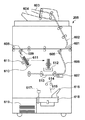
図6は、実施形態に係るくるみ製本機205の断面図である。   FIG. 6 is a cross-sectional view of the case binding machine 205 according to the embodiment.

ストレートパス601は、上流側から搬送されてきたメディアを下流側へ搬送するパスである。本実施形態においては、クリーサ装置204から受け取ったメディアを、フィニッシャ装置206へ搬送する。搬送パス602は、インサータトレイ603,604に給紙されたメディアをストレートパス601に搬送するための搬送パスである。これらインサータトレイ603,604は、印刷済のメディアを使ってくるみ製本を生成する場合に、印刷済みのメディアを給紙するためのトレイである。   The straight path 601 is a path for transporting the medium transported from the upstream side to the downstream side. In the present embodiment, the media received from the creaser device 204 is conveyed to the finisher device 206. A conveyance path 602 is a conveyance path for conveying the media fed to the inserter trays 603 and 604 to the straight path 601. These inserter trays 603 and 604 are trays for feeding printed media when generating bound book using printed media.

フラッパ605は、クリーサ装置204、インサータトレイ603,604から搬送されてきたメディアを、ストレートパス601もしくは搬送パス606に振り分けるものである。フラッパ605は、揺動軸を中心に揺動可能に構成され、メディアの搬送方向を規定する。フラッパ605が、図中時計回りの方向に揺動しているときは、メディアはストレートパス601に搬送され、図中反時計回りの方向に揺動しているときは、メディアは搬送パス606に搬送される。搬送速度制御ユニット607は、メディアの先端を検知するためのセンサを有しており、センサがメディアの先端を検知してから一定距離搬送した後に、メディアの搬送を停止する機能を有する。フラッパ608は、ストレートパス601から搬送されてきたメディアをストレートパス601、もしくは搬送パス609に振り分けるものである。フラッパ608は、揺動軸を中心に揺動可能に構成され、メディアの搬送方向を規定する。フラッパ608が、図中時計回りの方向に揺動しているときは、メディアはストレートパス601に搬送される。また、フラッパ608が、図中反時計回りの方向に揺動しているときは、メディアは搬送パス609に搬送される。搬送パス609は、メディアスタックユニット610へメディアを搬送するための搬送パスである。   The flapper 605 distributes the media conveyed from the cleaver device 204 and the inserter trays 603 and 604 to the straight path 601 or the conveyance path 606. The flapper 605 is configured to be swingable about a swing shaft, and defines the media transport direction. When the flapper 605 is swung in the clockwise direction in the figure, the medium is conveyed to the straight path 601, and when the flapper 605 is swung in the counterclockwise direction in the figure, the medium is moved to the conveying path 606. Be transported. The conveyance speed control unit 607 has a sensor for detecting the leading edge of the medium, and has a function of stopping the conveyance of the medium after the sensor detects the leading edge of the medium and conveys it for a certain distance. The flapper 608 distributes the media conveyed from the straight path 601 to the straight path 601 or the conveyance path 609. The flapper 608 is configured to be swingable about a swing shaft, and defines a medium transport direction. When the flapper 608 is swinging in the clockwise direction in the figure, the medium is conveyed to the straight path 601. Further, when the flapper 608 is swung in the counterclockwise direction in the drawing, the medium is transported to the transport path 609. The transport path 609 is a transport path for transporting media to the media stack unit 610.

メディアスタックユニット610は、くるみ製本の中紙をスタックするためのユニットである。メディアスタックユニット610は、正面側が解放されたコの字型になっており、正面側から背面側へ移動する機能を有している。グリッパ対611は、メディアスタックユニット610にスタックされた中紙束をグリップし、中紙束を糊付けユニット612にて糊付けした後、形成ローラ対614まで搬送する。糊付けユニット612は、くるみ製本の中紙束とくるみ製本の表紙とを糊付けするために利用する糊を溶解するユニットである。糊付けユニット612は、くるみ製本機動作中は、溶解された糊をユニット内に溜めており、更に、正面側から背面側へ移動する機能を有している。糊付け台613は、溶解した糊を付着させた中紙束と表紙とを糊付けする際に利用する糊付け台であり、正面側から背面側へ移動する機能を有している。形成ローラ対614は、糊付けされた中紙束と表紙を、くるみ製本の形状に形成する。形成ローラ対614は、上方から下方に向かって押し出す方向にローラ対を回転させている。そのため、形成ローラ対614は、グリッパ対611から、糊付けされた中紙束と表紙を受け取り、くるみ製本の背表紙側を下側にして、ガイド615に沿って回転台618に、形成されたくるみ製本を落とし込む。   The media stack unit 610 is a unit for stacking the case binding medium sheets. The media stack unit 610 has a U-shape with the front side released, and has a function of moving from the front side to the back side. The gripper pair 611 grips the bundle of intermediate sheets stacked on the media stack unit 610, glues the middle sheet bundle with the glue unit 612, and then conveys it to the forming roller pair 614. The gluing unit 612 is a unit that dissolves glue used for gluing the middle booklet of case binding and the cover of case binding. The glueing unit 612 stores the melted glue in the unit during operation of the case binding machine, and further has a function of moving from the front side to the back side. The gluing table 613 is a gluing table used when gluing the middle sheet bundle and the cover sheet to which the melted glue is adhered, and has a function of moving from the front side to the back side. The forming roller pair 614 forms the glued middle paper bundle and cover in the form of case binding. The forming roller pair 614 rotates the roller pair in a direction of pushing downward from above. Therefore, the forming roller pair 614 receives the glued inner paper bundle and cover from the gripper pair 611, and the case formed on the turntable 618 along the guide 615 with the back cover side of case binding facing down. Drop the bookbinding.

ガイド615は、形成されたくるみ製本の背表紙が、幅寄せ部616の方向を向くように落とし込むためのガイドである。幅寄せ部616は、形成されたくるみ製本を、カッタ617で切断するために位置調整を行う。カッタ617は、形成されたくるみ製本の小口及び天地を断裁するためのカッタである。回転台618は、形成されたくるみ製本を回転する機能を有し、くるみ製本の小口や天地を断裁する際に、カッタ617だけで、小口及び天地を断裁することを可能とする装置である。バスケット部619は、断裁されたくるみ製本の製本物を溜め置くための保管場所である。   The guide 615 is a guide for dropping the formed case binding spine so as to face the width-adjusting portion 616. The width adjusting portion 616 performs position adjustment in order to cut the formed case binding with a cutter 617. The cutter 617 is a cutter for cutting the small edge and top and bottom of the formed case binding. The turntable 618 is a device that has a function of rotating the formed case binding, and can cut the fore and top only with the cutter 617 when cutting the fore and top of the case binding. The basket portion 619 is a storage place for storing the trimmed case binding.

以下に、具体的に、くるみ製本を生成するときの動作を説明する。   The operation when generating case binding will be specifically described below.

くるみ製本の表紙となるメディアは、フラッパ605により、搬送パス606へ搬送される。そして、搬送速度制御ユニット607により、くるみ製本の表紙となるメディアの中心位置が、くるみ製本の背表紙の中心となる位置で、搬送を停止するように制御される。具体的には、くるみ製本の表紙となるメディアは、糊付け台613に配置されることになる。一方、くるみ製本の中紙となるメディアは、フラッパ605によりストレートパス501に搬送された後、フラッパ608により、搬送パス609を経由して、メディアスタックユニット610に搬送される。こうして中紙束がすべて揃うと、グリッパ対611は中紙束をグリップし、続いて、メディアスタックユニット610は、正面側から背面側へ移動する。このとき、グリッパ対611は、メディアスタックユニット610のコの字型の空間部分に位置しているため、メディアスタックユニット610が、背面側に移動することにより、糊付けユニット612にまで、中紙束を移動することが可能となる。   A medium serving as a cover for case binding is conveyed to a conveyance path 606 by a flapper 605. Then, the conveyance speed control unit 607 controls the conveyance to stop at the position where the center position of the case binding cover becomes the center of the case binding spine. Specifically, a medium serving as a cover for case binding is arranged on the gluing table 613. On the other hand, the medium serving as the inner paper for case binding is transported to the straight path 501 by the flapper 605 and then transported to the media stack unit 610 by the flapper 608 via the transport path 609. When all the intermediate sheet bundles are thus assembled, the gripper pair 611 grips the intermediate sheet bundle, and then the media stack unit 610 moves from the front side to the back side. At this time, since the gripper pair 611 is located in the U-shaped space portion of the media stack unit 610, the media stack unit 610 moves to the back side, so that it reaches the gluing unit 612 and reaches the middle sheet bundle. It becomes possible to move.

グリッパ対611は、中紙束の背表紙方向が下方向になるように回転しながら、糊付けユニット612に移動して糊付けを行う。そして、糊付けが完了すると、グリッパ対611は、一度、中紙束を上方向に移動し、更に、糊付けユニット612を、正面側から背面側へ移動する。糊付けユニット612の移動が完了すると、グリッパ対611は、下方向に移動し、糊付け台613に配置されたくるみ製本の表紙となるメディアに、中紙束を接着させる。こうして接着が完了した後、糊付け台613は、正面側から背面側へ移動し、その移動が完了すると、グリッパ対611は下方向に移動し、形成ローラ614にて、くるみ製本の形成を行う。   The gripper pair 611 moves to the gluing unit 612 to perform gluing while rotating so that the spine cover direction of the middle paper bundle is downward. When the gluing is completed, the gripper pair 611 once moves the middle sheet bundle upward, and further moves the gluing unit 612 from the front side to the back side. When the movement of the gluing unit 612 is completed, the gripper pair 611 moves downward, and the middle paper bundle is adhered to the medium serving as the cover of the case binding arranged on the gluing table 613. After the bonding is completed, the gluing table 613 moves from the front side to the back side. When the movement is completed, the gripper pair 611 moves downward, and the forming roller 614 forms the case binding.

こうして、形成されたくるみ製本は、形成ローラ614により、ガイド615に沿って、下方向に押し出されるため、背表紙側が幅寄せ部616に向いた形で、回転台616上に配置される。回転台618の上に横たわる形成されたくるみ製本は、幅寄せ部616で位置を合わせられ、小口となる部分をカッタ617で断裁される。次に、回転台618が90度回転して、幅寄せ部616で位置合わせを行い、天となる部分を断裁する。更に、回転台618が180度回転して、幅寄せ部616で位置合わせを行い、地となる部分を断裁する。こうして断裁されたくるみ製本の製本物は、幅寄せ部616で図中左側に押しやられ、バスケット部619に入れられる。   The case binding thus formed is pushed downward along the guide 615 by the forming roller 614, and is thus arranged on the turntable 616 with the spine cover side facing the width adjusting portion 616. The case binding formed on the turntable 618 is aligned with the width adjusting portion 616, and the portion that becomes the fore edge is cut with the cutter 617. Next, the turntable 618 is rotated 90 degrees, the alignment is performed by the width adjusting portion 616, and the top portion is cut. Further, the turntable 618 rotates 180 degrees, aligns with the width adjusting portion 616, and cuts the ground portion. The case-bound product thus cut is pushed to the left in the drawing by the width adjusting portion 616 and is put into the basket portion 619.

図7は、実施形態に係るフィニッシャ装置206の断面図である。   FIG. 7 is a cross-sectional view of the finisher device 206 according to the embodiment.

搬送パス701は、上流側から搬送されてきたメディアをフィニッシャ装置206へ搬送するパスである。本実施形態においては、フィニッシャ装置206は、くるみ製本機205のストレートパス601から搬送されてきたメディアを受け取り、フィニッシャ装置206内部へ搬送する。搬送パス702は、インサータトレイ703,704に給紙されたメディアを搬送パス701に搬送するための搬送パスである。インサータトレイ603,604は、印刷済のメディアを使って、パンチ、ステイプル、中綴じ製本などの製本物を生成する場合に、印刷済みのメディアを給紙するためのトレイである。   The transport path 701 is a path for transporting the media transported from the upstream side to the finisher device 206. In the present embodiment, the finisher device 206 receives the media transported from the straight path 601 of the case binding machine 205 and transports the media into the finisher device 206. The transport path 702 is a transport path for transporting the media fed to the inserter trays 703 and 704 to the transport path 701. The inserter trays 603 and 604 are trays for feeding printed media when the printed media is used to generate a bookbinding product such as punching, stapling, or saddle stitching binding.

フラッパ705は、揺動軸を中心に揺動可能に構成され、搬送パス701もしくは搬送パス702にて搬送されてきたメディアの搬送方向を規定する。フラッパ705が、図中反時計回りの方向に揺動している時には、メディアは搬送パス706へ搬送される。また、図中時計回りの方向に揺動している時には、メディアは搬送パス707へ搬送される。フラッパ708は、揺動軸を中心に揺動可能に構成され、搬送パス707にて搬送されてきたメディアの搬送方向を規定する。フラッパ708が、図中反時計回りの方向に揺動している場合は、メディアは搬送パス710へ搬送される。また、図中時計回りの方向に揺動している時には、メディアは搬送パス709へ搬送される。搬送パス709は、メディアをサンプルトレイ711へ搬送するための搬送パスである。また、搬送パス710は、メディアをスタックトレイ714へ搬送するための搬送パスである。サンプルトレイ711は、搬送パス709を通過したメディアが排出されるトレイである。搬送パス710に搬送されたメディアは、パンチャ712、ステープラ713を通過し、スタックトレイ714に搬送される。   The flapper 705 is configured to be swingable about a swing shaft, and defines the transport direction of the media transported in the transport path 701 or the transport path 702. When the flapper 705 is swinging in the counterclockwise direction in the figure, the medium is transported to the transport path 706. In addition, the medium is transported to the transport path 707 when swinging in the clockwise direction in the figure. The flapper 708 is configured to be swingable about a swing shaft, and defines the transport direction of the media transported by the transport path 707. When the flapper 708 is swinging in the counterclockwise direction in the drawing, the medium is transported to the transport path 710. In addition, the medium is transported to the transport path 709 when swinging in the clockwise direction in the drawing. A conveyance path 709 is a conveyance path for conveying the medium to the sample tray 711. The transport path 710 is a transport path for transporting media to the stack tray 714. The sample tray 711 is a tray from which the media that has passed through the transport path 709 is discharged. The media conveyed to the conveyance path 710 passes through the puncher 712 and the stapler 713 and is conveyed to the stack tray 714.

パンチャ712は、搬送パス710を通過するメディアに穴あけ処理を施す。パンチャ712は、入れ替え可能な2穴や3穴などの刃(不図示)を有しており、刃を入れ替えることで、メディアに対して任意の数の穴を開けることが可能である。ステープラ713は、搬送パス710を通過するメディアをスタックし、ステイプル処理を施す。ステープラ713は、補充可能な刃(不図示)を有しており、角止め、2カ所止めなど各種ステイプル処理が可能である。スタックトレイ714は、搬送パス710を通過したメディアが排出されるトレイである。   The puncher 712 performs punching processing on the medium passing through the transport path 710. The puncher 712 has blades (not shown) such as two holes or three holes that can be replaced, and by replacing the blades, an arbitrary number of holes can be formed in the media. The stapler 713 stacks media passing through the transport path 710 and performs stapling processing. The stapler 713 has a refillable blade (not shown), and can perform various stapling processes such as a corner stop and a two-point stop. The stack tray 714 is a tray from which the media that has passed through the transport path 710 is discharged.

搬送パス706は、中綴じ処理を施す場合に、メディアを搬送する搬送パスである。ストッパ715は、搬送パス706から搬送されてきたメディアを停止させるためのストッパである。ストッパ715は、モータ(不図示)により、ストッパ715から折り込みプレート716間の長さを調整できる。通常、中綴じ処理を施すメディアの搬送方向の長さの二分の一の長さに設定する。つまり、中綴じ処理は、中綴じ処理を施すメディアの中央に施される。折り込みプレート716は、ストッパ715にて停止させたメディアをサドルステッチャ717へ押し込むための装置である。サドルステッチャ717は、折り込みプレート716によって、押し込まれたメディアに対して、ステイプル処理と折り込み処理を施す。ストッパ715と折り込みプレート716の働きにより、メディアの真ん中が折り込まれて、サドルステッチャ717に入ってくる。そのため、サドルステッチャ717を通過すると、中綴じ処理を施されたメディアが、スタック部718に搬送される。そして、中綴じ処理を施されたメディアは、機外排出ローラ719により、スタック部718からサドルトレイ720へ排出される。ガイド721は、中綴じ処理を施されたメディアを留め置き、順次1冊ずつ、サドルスタック部722へ送り込む働きを持つ。サドルスタック部722は、中綴じ処理を施されたメディアを大量に溜め置くものである。   The transport path 706 is a transport path for transporting media when performing saddle stitching processing. The stopper 715 is a stopper for stopping the medium conveyed from the conveyance path 706. The stopper 715 can adjust the length between the stopper 715 and the folding plate 716 by a motor (not shown). Usually, the length is set to one half of the length of the medium to be subjected to saddle stitching in the conveyance direction. That is, the saddle stitching process is performed at the center of the medium on which the saddle stitching process is performed. The folding plate 716 is a device for pushing the media stopped by the stopper 715 into the saddle stitcher 717. The saddle stitcher 717 performs a stapling process and a folding process on the pushed-in medium by the folding plate 716. The middle of the medium is folded by the action of the stopper 715 and the folding plate 716 and enters the saddle stitcher 717. Therefore, after passing through the saddle stitcher 717, the medium subjected to the saddle stitching process is conveyed to the stack unit 718. Then, the media subjected to the saddle stitching process is discharged from the stack unit 718 to the saddle tray 720 by an external discharge roller 719. The guide 721 has a function of retaining the media subjected to the saddle stitching process and sequentially feeding the books one by one to the saddle stack unit 722. The saddle stack unit 722 stores a large amount of media subjected to the saddle stitching process.

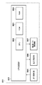
図8は、実施形態に係る画像形成装置101のハードウェア構成を説明するブロック図である。   FIG. 8 is a block diagram illustrating a hardware configuration of the image forming apparatus 101 according to the embodiment.

CPU回路部801はCPU802を有し、ROM803に格納されているプログラムに従って、次に示す各制御部をコントロールする。まず、印刷に関する制御部として、操作パネル制御部805、原稿給紙装置制御部806、イメージリーダ制御部807、画像信号制御部808、プリンタ制御部809、給紙装置制御部810を制御する。印刷物の形成に関する制御部として、クリーサ制御部811、くるみ製本制御部812、フィニッシャ制御部813を制御する。更に、内部および外部とのインタフェース制御部として、HDD815を制御するためのHDD・I/F部814、ネットワークI/F部816も制御する。RAM804は制御データを一時的に保持する領域や、制御に伴う演算の作業領域として用いられる。   The CPU circuit unit 801 has a CPU 802 and controls the following control units according to a program stored in the ROM 803. First, an operation panel control unit 805, a document feeding device control unit 806, an image reader control unit 807, an image signal control unit 808, a printer control unit 809, and a paper feeding device control unit 810 are controlled as control units related to printing. As a control unit related to the formation of the printed matter, the creaser control unit 811, the case binding control unit 812, and the finisher control unit 813 are controlled. Further, as an internal and external interface control unit, an HDD / I / F unit 814 and a network I / F unit 816 for controlling the HDD 815 are also controlled. The RAM 804 is used as an area for temporarily storing control data and a work area for operations associated with control.

操作パネル制御部805は、操作パネル425を制御する。原稿給紙装置制御部806は、自動原稿搬送装置(ADF)423を制御する。イメージリーダ制御部807はスキャナ424を制御する。画像信号制御部808は、受け取った画像データに対して画像処理を施した後に、プリンタ制御部809が解釈可能な画像信号に変換し、プリンタ制御部809へ渡す制御を行う。プリンタ制御部809は、現像ユニット405、現像ユニット406、現像ユニット407、現像ユニット408、第一定着部413、第二定着部414等を制御する。給紙装置制御部810は、外部給紙装置201、外部給紙装置202、画像形成装置本体203の給紙トレイを制御する。   The operation panel control unit 805 controls the operation panel 425. A document feeder controller 806 controls an automatic document feeder (ADF) 423. The image reader control unit 807 controls the scanner 424. The image signal control unit 808 performs image processing on the received image data, converts the image data into an image signal that can be interpreted by the printer control unit 809, and performs control to pass to the printer control unit 809. A printer control unit 809 controls the developing unit 405, the developing unit 406, the developing unit 407, the developing unit 408, the first fixing unit 413, the second fixing unit 414, and the like. A paper feeding device control unit 810 controls the paper feeding trays of the external paper feeding device 201, the external paper feeding device 202, and the image forming apparatus main body 203.

クリーサ制御部811はクリーサ装置204を制御する。くるみ製本制御部812はくるみ製本機205を制御する。フィニッシャ制御部813は、フィニッシャ装置206を制御する。HDD・I/F部814はCPU回路部801とHDD815とのインタフェースであり、HDD815に対する書き込みや読み出しを制御する。ネットワークI/F部816は、ネットワーク103を介したデータの送受信を制御する。HDD815は、大容量記憶装置であり、不揮発性のデータを保存する領域である。ネットワークI/F部816は、ネットワーク103を介して画像処理装置102(図1)と接続されている。   The creaser control unit 811 controls the creaser 204. The case binding control unit 812 controls the case binding machine 205. The finisher control unit 813 controls the finisher device 206. The HDD / I / F unit 814 is an interface between the CPU circuit unit 801 and the HDD 815, and controls writing to and reading from the HDD 815. The network I / F unit 816 controls data transmission / reception via the network 103. The HDD 815 is a mass storage device, and is an area for storing nonvolatile data. The network I / F unit 816 is connected to the image processing apparatus 102 (FIG. 1) via the network 103.

コピー動作時のCPU回路部801による各制御部に対する制御について説明する。   The control of each control unit by the CPU circuit unit 801 during the copy operation will be described.

CPU回路部801は、操作パネル制御部805からのコピー指示を受けると、原稿給紙装置制御部806を介して自動原稿搬送装置(ADF)423に、原稿束を1枚ずつフィードするように指示する。そして、CPU回路部801は、イメージリーダ制御部807を使い、スキャナ424に、原稿を読み取り画像データを生成させる。次に、CPU回路部801は、生成した画像データを、RAM804に一次保存し、画像信号制御部808へ転送する。そしてCPU回路部801は、画像信号制御部808にプリンタ制御部809が解釈可能な画像信号に変換し、プリンタ制御部809へ画像信号を渡すよう指示する。同時に、CPU回路部801は、給紙装置制御部810を使い、外部給紙装置201、外部給紙装置202などから印刷用のメディアを給紙するように指示する。   When the CPU circuit unit 801 receives a copy instruction from the operation panel control unit 805, the CPU circuit unit 801 instructs the automatic document feeder (ADF) 423 to feed a bundle of documents one by one via the document feeder control unit 806. To do. The CPU circuit unit 801 uses the image reader control unit 807 to cause the scanner 424 to read a document and generate image data. Next, the CPU circuit unit 801 primarily stores the generated image data in the RAM 804 and transfers it to the image signal control unit 808. The CPU circuit unit 801 instructs the image signal control unit 808 to convert the image signal into an image signal that can be interpreted by the printer control unit 809 and to pass the image signal to the printer control unit 809. At the same time, the CPU circuit unit 801 uses the paper feeding device control unit 810 to instruct to feed printing media from the external paper feeding device 201, the external paper feeding device 202, and the like.

プリンタ制御部809は、現像ユニット405、現像ユニット406、現像ユニット407、現像ユニット408、第一定着部413、第二定着部414等を制御し、前記給紙したメディアに読み取った画像を形成する。その後、画像形成されたメディアは、オペレータ指定の出力形態に応じて後処理を施される。ここで、後処理とは、クリーサ制御部811、くるみ製本制御部812、フィニッシャ制御部813により施される処理を示す。   A printer control unit 809 controls the developing unit 405, the developing unit 406, the developing unit 407, the developing unit 408, the first fixing unit 413, the second fixing unit 414, and the like, and forms a read image on the fed medium. To do. Thereafter, the media on which the image has been formed is subjected to post-processing according to the output form designated by the operator. Here, post-processing refers to processing performed by the creaser control unit 811, the case binding control unit 812, and the finisher control unit 813.

例えば、メディアにクリース処理を施す場合は、CPU回路部801は、クリーサ制御部811を使って、メディアに対するクリース処理を実施する。その後、くるみ製本を形成する場合は、CPU回路部801が、くるみ製本制御部812を使って、くるみ製本の形成処理を行いバスケット部619に排出させる。また、フィニッシャ装置205に排紙される場合は、CPU回路部801が、フィニッシャ制御部813を使って、指定された排紙先や、中綴じおよび2穴パンチなど指定されたフィニッシング設定に応じた処理を行う。そして、処理を施されたメディアを、サンプルトレイ711、スタックトレイ714、サドルスタック部722のいずれかに排紙させる。   For example, when the crease process is performed on the medium, the CPU circuit unit 801 uses the creaser control unit 811 to perform the crease process on the medium. Thereafter, when forming the case binding, the CPU circuit unit 801 uses the case binding control unit 812 to perform the case binding forming process, and discharges it to the basket unit 619. When the sheet is discharged to the finisher device 205, the CPU circuit unit 801 uses the finisher control unit 813 to respond to a specified discharge destination, a specified finishing setting such as saddle stitching and two-hole punching. Process. Then, the processed media is discharged to one of the sample tray 711, the stack tray 714, and the saddle stack unit 722.

次に、プリント動作時のCPU回路部801による各制御部に対する制御について説明する。   Next, control of each control unit by the CPU circuit unit 801 during the printing operation will be described.

CPU回路部801は、ネットワークI/F816を経由して、例えば画像処理装置102から印刷画像データを受信する。次に、CPU回路部801は、受信した画像データを、RAM804に一次保存し、画像信号制御部808へ転送する。その後は、コピー動作時と同様であるので、説明は省略する。   The CPU circuit unit 801 receives print image data from, for example, the image processing apparatus 102 via the network I / F 816. Next, the CPU circuit unit 801 primarily stores the received image data in the RAM 804 and transfers it to the image signal control unit 808. After that, since it is the same as that at the time of the copy operation, the description is omitted.

図9は、実施形態に係るクリーサ制御部811の詳細な構成を示すブロック図である。   FIG. 9 is a block diagram illustrating a detailed configuration of the creaser control unit 811 according to the embodiment.

CPU回路部901はCPU902を有し、ROM903に格納されているプログラムに従って、次に示す制御部をコントロールする。制御部とは、ダイ検知部905、圧力制御部906、搬送パス制御部907である。また、RAM904は制御データを一時的に保持する領域や、制御に伴う演算の作業領域として用いられる。CPU回路部901は、CPU回路部801とダイ検知部905、圧力制御部906、搬送パス制御部907との間の仲介回路である。CPU回路部901は、CPU回路部801からの指示や制御部からの通知を仲介する機能を持つ。   The CPU circuit unit 901 has a CPU 902 and controls the following control unit according to a program stored in the ROM 903. The control units are a die detection unit 905, a pressure control unit 906, and a conveyance path control unit 907. The RAM 904 is used as an area for temporarily storing control data and a work area for operations associated with control. The CPU circuit unit 901 is an intermediary circuit between the CPU circuit unit 801, the die detection unit 905, the pressure control unit 906, and the conveyance path control unit 907. The CPU circuit unit 901 has a function of mediating an instruction from the CPU circuit unit 801 and a notification from the control unit.

ダイ検知部905は、クリース用ダイ504が、クリーサ装置204に装着されているか否かを検知する検知部である。圧力制御部906は、圧力装置506〜508を制御し、クリース用ダイ504に圧力を加えることでクリースを行う。搬送パス制御部907は、フラッパ503、搬送速度制御ユニット510などを制御し、メディアの搬送パス切り替えや、搬送速度のコントロールを行う。つまり、CPU回路部801は、CPU回路部901を通じて、ダイ検知部905、圧力制御部906、搬送パス制御部907を集中制御できる構成となっており、クリーサ装置204に対するクリース処理や搬送パス制御をコントロール可能である。   The die detection unit 905 is a detection unit that detects whether or not the crease die 504 is attached to the creaser device 204. The pressure control unit 906 controls the pressure devices 506 to 508 to perform crease by applying pressure to the crease die 504. The transport path control unit 907 controls the flapper 503, the transport speed control unit 510, and the like, and performs media transport path switching and transport speed control. That is, the CPU circuit unit 801 is configured to centrally control the die detection unit 905, the pressure control unit 906, and the conveyance path control unit 907 through the CPU circuit unit 901, and performs crease processing and conveyance path control on the creaser device 204. It can be controlled.

図10は、実施形態に係る画像処理装置102のハードウェア構成を説明するブロック図である。   FIG. 10 is a block diagram illustrating a hardware configuration of the image processing apparatus 102 according to the embodiment.

CPU1001は、ROM1007、HDD1009及びCDD1006に格納された制御プログラムに基づいてCPUデバイスに接続された各デバイスを制御する。表示部1002の表示画面には、例えばウインドウ、アイコン、メッセージ、メニューその他のオペレータインターフェース情報が表示される。VRAM1003は表示部1002に表示するための表示画像が描画される。このVRAM1003に生成された表示用の画像データは、所定の規定に従って表示部1002に転送され、これにより表示部1102に画像が表示される。キーボード1004は、文字を入力するための各種キーを有する。PD(ポインティングデバイス)1005は、例えば、表示部1002の表示画面上に表示されたアイコン、メニューその他のオブジェクトを指示するために使用される。CDD(コンパクトディスクドライブ)1006は、CD−ROMや、CD−Rなどの記録メディアとの間で各種制御プログラムやデータの読み書きを行う装置である。これはDVDドライブであってもよい。ROM(リードオンリメモリ)1007は、各種の制御プログラムやデータを保持する。RAM(ランダムアクセスメモリ)1008は、CPU1001のワーク領域、エラー処理時のデータの退避領域、制御プログラムのロード領域等を有する。例えば、画像処理装置102は、電子データをRIPして画像形成装置101へ送信する機能を有している。そのプログラムはROM1007に格納されており、RIP処理を行う際にはCPU1001のワーク領域やRAM1008を利用する。HDD(ハードディスクドライブ)1009は、各種制御プログラムや各種データを保存する。外部記録I/F1010は、USBメモリなどの外部記録媒体への読み書きを行う。ネットワーク・インターフェース(Net−I/F)1011は、ネットワーク103を介して、データの送受信を行う。本実施形態で画像処理装置102は、画像形成装置101との間で、ネットワーク103を介してデータの送受信を行うことができる。CPUバス1013は、アドレスバス、データバス及びコントロールバスを含む。   The CPU 1001 controls each device connected to the CPU device based on a control program stored in the ROM 1007, the HDD 1009, and the CDD 1006. On the display screen of the display unit 1002, for example, windows, icons, messages, menus, and other operator interface information are displayed. A display image to be displayed on the display unit 1002 is drawn on the VRAM 1003. The display image data generated in the VRAM 1003 is transferred to the display unit 1002 in accordance with a predetermined rule, whereby an image is displayed on the display unit 1102. The keyboard 1004 has various keys for inputting characters. A PD (pointing device) 1005 is used, for example, to instruct icons, menus, and other objects displayed on the display screen of the display unit 1002. A CDD (Compact Disk Drive) 1006 is a device that reads and writes various control programs and data with a recording medium such as a CD-ROM or CD-R. This may be a DVD drive. A ROM (Read Only Memory) 1007 holds various control programs and data. A RAM (Random Access Memory) 1008 has a work area for the CPU 1001, a data save area for error processing, a control program load area, and the like. For example, the image processing apparatus 102 has a function of transmitting electronic data to the image forming apparatus 101 by RIP. The program is stored in the ROM 1007, and uses the work area of the CPU 1001 and the RAM 1008 when performing RIP processing. An HDD (Hard Disk Drive) 1009 stores various control programs and various data. The external recording I / F 1010 performs reading and writing to an external recording medium such as a USB memory. A network interface (Net-I / F) 1011 transmits and receives data via the network 103. In this embodiment, the image processing apparatus 102 can transmit and receive data to and from the image forming apparatus 101 via the network 103. The CPU bus 1013 includes an address bus, a data bus, and a control bus.

図11は、実施形態に係る画像形成装置101と画像処理装置102のソフトウェア構成を説明するブロック図である。   FIG. 11 is a block diagram illustrating software configurations of the image forming apparatus 101 and the image processing apparatus 102 according to the embodiment.

UI処理部1101、機器制御部1102、受信処理部1103、送信処理部1104、ネットワークI/F制御部1105は、画像形成装置101のCPU回路部801にて実行されるソフトウェアである。またUI処理部1106、ジョブ制御部1107、RIP処理部1108、受信処理部1109、送信処理部1110、ネットワークI/F制御部1111は、画像処理装置102のCPU1001にて実行されるソフトウェアである。   The UI processing unit 1101, the device control unit 1102, the reception processing unit 1103, the transmission processing unit 1104, and the network I / F control unit 1105 are software executed by the CPU circuit unit 801 of the image forming apparatus 101. The UI processing unit 1106, job control unit 1107, RIP processing unit 1108, reception processing unit 1109, transmission processing unit 1110, and network I / F control unit 1111 are software executed by the CPU 1001 of the image processing apparatus 102.

まず画像形成装置101の構成について説明する。   First, the configuration of the image forming apparatus 101 will be described.

UI処理部1101は、操作パネル制御部805を制御し、操作パネル425に画像形成装置101に関する設定画面の表示などを担当する。そして、UI処理部1101は、設定画面にて設定された設定値を画像形成装置101のHDD815への保存や読み出しを行う処理を担当する。機器制御部1102は、CPU回路部801を制御し、画像形成装置本体203の画像形成機能、クリース装置204のクリース機能、くるみ製本機205でのくるみ製本形成、フィニッシャ装置206での中綴じ製本生成などの処理を担当する。更に機器制御部1102は、画像形成装置101のHDD815から印刷に関する設定を読み出し、印刷処理に反映する処理も担当する。受信処理部1103は、画像処理装置102によりRIPされた印刷画像を、ネットワークI/F制御部1105を通じて受信し、ページ単位で機器制御部1102へ渡す処理を担当する。送信処理部1104は、画像形成装置101にて発生したイベントや状態変更の通知などを、ネットワークI/F制御部1105を通じて送信する。ネットワークI/F制御部1105は、ネットワークI/F816を制御する。更に、画像処理装置102のネットワークI/F制御部1111と連携し、ネットワーク103を通じて、画像形成装置101と画像処理装置102との間のデータ通信処理を担当する。   The UI processing unit 1101 controls the operation panel control unit 805 and takes charge of displaying a setting screen related to the image forming apparatus 101 on the operation panel 425. The UI processing unit 1101 is in charge of processing for saving and reading the setting value set on the setting screen to the HDD 815 of the image forming apparatus 101. The device control unit 1102 controls the CPU circuit unit 801 to generate the image forming function of the image forming apparatus main body 203, the crease function of the crease apparatus 204, the case binding formation with the case binding machine 205, and the saddle stitch bookbinding generation with the finisher apparatus 206. In charge of such processing. Further, the device control unit 1102 is also in charge of processing for reading settings related to printing from the HDD 815 of the image forming apparatus 101 and reflecting them in the printing processing. The reception processing unit 1103 is in charge of processing to receive the print image RIPed by the image processing apparatus 102 through the network I / F control unit 1105 and pass it to the device control unit 1102 in units of pages. A transmission processing unit 1104 transmits an event that has occurred in the image forming apparatus 101, a notification of a state change, and the like through the network I / F control unit 1105. The network I / F control unit 1105 controls the network I / F 816. Further, in cooperation with the network I / F control unit 1111 of the image processing apparatus 102, it is in charge of data communication processing between the image forming apparatus 101 and the image processing apparatus 102 through the network 103.

次に画像処理装置102の構成について説明する。   Next, the configuration of the image processing apparatus 102 will be described.

UI処理部1106は、画像処理装置102の表示部1002に、画像形成装置101と画像処理装置102が印刷ジョブを実行するときの制御設定画面を表示する処理を担当する。ジョブ制御部1107は、画像形成装置101に対する印刷ジョブの送信処理を担当する。具体的には、印刷ジョブの印刷開始要求やジョブ設定情報の送信などの処理を行う。RIP処理部1108は、印刷データをページ単位でRIPする処理を担当する。受信処理部1109は、ネットワークI/F制御部1111を通じて、画像形成装置101からのイベントや状態変更などを受信し、UI処理部1106へ渡す処理を担当する。送信処理部1110は、RIP画像を、ページ単位で、ネットワークI/F制御部1111を通じて、画像形成装置101の受信処理部1103に渡す処理を担当する。ネットワークI/F制御部1111は、Net−I/F1011を制御する。更に、画像形成装置101のネットワーク制御部1105と連携し、ネットワーク103を通じて、画像形成装置101との間のデータ通信処理を担当する。   The UI processing unit 1106 is in charge of processing for displaying a control setting screen when the image forming apparatus 101 and the image processing apparatus 102 execute a print job on the display unit 1002 of the image processing apparatus 102. A job control unit 1107 is responsible for print job transmission processing for the image forming apparatus 101. Specifically, processing such as a print start request for a print job and transmission of job setting information is performed. The RIP processing unit 1108 is in charge of RIP processing print data in units of pages. A reception processing unit 1109 receives an event or a status change from the image forming apparatus 101 via the network I / F control unit 1111 and takes charge of processing to pass to the UI processing unit 1106. The transmission processing unit 1110 is in charge of processing to pass the RIP image to the reception processing unit 1103 of the image forming apparatus 101 through the network I / F control unit 1111 in units of pages. The network I / F control unit 1111 controls the Net-I / F 1011. Further, in cooperation with the network control unit 1105 of the image forming apparatus 101, it is in charge of data communication processing with the image forming apparatus 101 through the network 103.

このような構成において、画像処理装置102が印刷ジョブをRIPし、画像形成装置101で印刷する場合は、以下の処理を行うことで実現する。   In such a configuration, when the image processing apparatus 102 RIPs a print job and prints it with the image forming apparatus 101, the following processing is performed.

まず、画像処理装置102のジョブ制御部1107は、UI処理部1106にて設定されたジョブ設定に従って印刷ジョブを生成する。次に、ジョブ制御部1107は、印刷ジョブをRIP処理部1108によりページ単位でレンダリングし、送信処理部1110を介して、その画像データを画像形成装置101の機器制御部1102へ送信する。更に、ジョブ制御部1107は、画像データの送信に併せて、ネットワークI/F制御部1111を通じて、ジョブ設定情報を画像形成装置101の機器制御部1102へ送信する。   First, the job control unit 1107 of the image processing apparatus 102 generates a print job according to the job setting set by the UI processing unit 1106. Next, the job control unit 1107 renders the print job on a page basis by the RIP processing unit 1108, and transmits the image data to the device control unit 1102 of the image forming apparatus 101 via the transmission processing unit 1110. Further, the job control unit 1107 transmits job setting information to the device control unit 1102 of the image forming apparatus 101 through the network I / F control unit 1111 together with the transmission of the image data.

次に、画像形成装置101の機器制御部1102は、受信した画像データを受け取り、その画像データを画像信号制御部808へ渡すとともに、ジョブ設定情報を受信する。続いて、機器制御部1102は、ジョブ設定情報を基に、プリンタ制御部809、給紙装置制御部810、クリーサ制御部811、くるみ製本制御部812、フィニッシャ制御部813を制御する。そして機器制御部1102は、各制御部へ、給紙トレイ、排紙先、クリースの有無、フィニッシング形態(くるみ製本、中綴じ製本、パンチ、ステイプル)などに関する指示を出す。この時、機器制御部1102は、画像形成装置101のHDD815から印刷に関する設定を読み出し、必要に応じて、印刷処理に反映する。そして、上述の指示を出すと共に、画像信号制御部808へ、画像データをプリンタ制御部809へ渡すように指示する。   Next, the device control unit 1102 of the image forming apparatus 101 receives the received image data, passes the image data to the image signal control unit 808, and receives job setting information. Subsequently, the device control unit 1102 controls the printer control unit 809, the sheet feeding device control unit 810, the cleaner control unit 811, the case binding control unit 812, and the finisher control unit 813 based on the job setting information. The device control unit 1102 then instructs each control unit regarding a paper feed tray, a paper discharge destination, the presence or absence of crease, a finishing form (case binding, saddle stitch binding, punch, staple), and the like. At this time, the device control unit 1102 reads the settings relating to printing from the HDD 815 of the image forming apparatus 101 and reflects them in the printing process as necessary. In addition to issuing the above instruction, the image signal control unit 808 is instructed to pass the image data to the printer control unit 809.

以上により、画像が印刷されたメディアは、ジョブ設定情報及びHDD815に保存された印刷に関する設定に従って、クリース処理を施した印刷物に生成される。   As described above, the medium on which the image is printed is generated as a crease-processed printed material according to the job setting information and the settings related to printing stored in the HDD 815.

図12(A)及び図12(B)は、実施形態に係る画像処理装置102の表示部1002に表示されるジョブ設定画面例を示す図である。   12A and 12B are diagrams illustrating an example of a job setting screen displayed on the display unit 1002 of the image processing apparatus 102 according to the embodiment.

図12(A)は、ジョブ設定画面の一例を示す図である。   FIG. 12A illustrates an example of a job setting screen.

タグ1201は、ジョブ設定項目を種類によってグループ化したタグであり、「一般」、「ジョブ情報」、「メディア」、「レイアウト」、「仕上げ」の5種類により構成されている。そして、図12(A)では、「メディア」が選択されて、その設定項目が表示されている。「メディア」は、印刷ジョブが使用するメディアに関連する設定をまとめたタグである。メディア種類1202、メディアサイズ1203、給紙トレイ1204は、くるみ製本表紙、もしくは中綴じ製本に使うメディアに関する設定項目である。図中、メディア種類1202では、普通紙が選択されており、メディアサイズ1203では、A3が選択されており、給紙トレイ1204では、自動選択が選択されている。つまり、図12(A)の設定では、メディアタイプが普通紙で、サイズがA3に設定されている給紙トレイであれば、どの給紙トレイからでも給紙して印刷するように設定されている。   A tag 1201 is a tag in which job setting items are grouped according to type, and includes five types of “general”, “job information”, “media”, “layout”, and “finish”. In FIG. 12A, “Media” is selected and its setting items are displayed. “Media” is a tag that summarizes settings related to media used by a print job. A media type 1202, a media size 1203, and a paper feed tray 1204 are setting items relating to media used for case binding cover or saddle stitch binding. In the figure, plain paper is selected for the media type 1202, A3 is selected for the media size 1203, and automatic selection is selected for the paper feed tray 1204. That is, in the setting shown in FIG. 12A, if the media type is plain paper and the size is set to A3, the paper is set to be fed from any paper feed tray for printing. Yes.

メディア種類1205、メディアサイズ1206、給紙トレイ1207は、くるみ製本中紙に使うメディアに関する設定項目である。図12(A)では、メディア種類1205は普通紙が選択されており、メディアサイズ1206はA4、給紙トレイ1206は自動選択が選択されている。つまり、図中の設定では、メディアタイプが普通紙で、メディアサイズがA4と設定されている給紙トレイであれば、どの給紙トレイからでも給紙して印刷するように設定されている。   A media type 1205, a media size 1206, and a paper feed tray 1207 are setting items related to media used for case binding medium paper. In FIG. 12A, plain paper is selected as the media type 1205, A4 is selected as the media size 1206, and automatic selection is selected as the paper feed tray 1206. In other words, in the setting in the figure, if the media type is plain paper and the media size is set to A4, it is set to feed and print from any paper feed tray.

OKボタン1208は、このジョブ設定画面で設定した内容をジョブ設定として決定するボタンである。キャンセルボタン1209は、ジョブ設定画面で設定した内容を破棄するボタンである。尚、OKボタン1208或いはキャンセルボタン1209が押下されると、このジョブ設定画面は閉じられる。   An OK button 1208 is a button for determining the contents set on the job setting screen as job settings. A cancel button 1209 is a button for discarding the contents set on the job setting screen. If the OK button 1208 or the cancel button 1209 is pressed, this job setting screen is closed.

図12(B)は、「仕上げ」の設定画面の一例を示す図である。   FIG. 12B is a diagram illustrating an example of a “finish” setting screen.

「仕上げ」は、排紙に関する設定をまとめたタグである。排紙先1208は、排紙先の指定に関する設定であり、図中では、くるみ製本機が指定されている。ここで、本設定は、くるみ製本機以外にも、フィニッシャ装置206のサンプルトレイ711、スタックトレイ714、サドルスタック部722などが選択可能である。パンチ1209は、フィニッシャ装置206に排出する際に、メディアに穴あけ処理を行うか否かを設定する項目である。図中では、パンチは「しない」に指定されている。ステイプル1210は、フィニッシャ装置206に排出する際に、メディアにステイプル処理を行うか否かを設定する項目である。図中では、ステイプル設定は「しない」に指定されている。中綴じ製本1211は、フィニッシャ装置206に排出する際に、メディアに中綴じ処理を行うか否かを設定する項目である。図中では、中綴じ処理は「しない」に設定されている。くるみ製本1212は、くるみ製本機205で、くるみ製本を形成する場合に設定する項目である。図中では、くるみ製本を左中綴じで形成するように設定されている。OKボタン1208、及びキャンセルボタン1209については、図12(A)での説明と同様であるため、説明を省略する。   “Finishing” is a tag that summarizes settings related to paper discharge. The paper discharge destination 1208 is a setting relating to the specification of the paper discharge destination. In the drawing, the case binding machine is specified. In this setting, the sample tray 711, stack tray 714, saddle stack unit 722, and the like of the finisher device 206 can be selected in addition to the case binding machine. The punch 1209 is an item for setting whether or not to perform a hole punching process on the medium when discharging to the finisher device 206. In the figure, punching is designated as “no”. A staple 1210 is an item for setting whether or not to perform a stapling process on a medium when the staple is ejected to the finisher device 206. In the figure, the stapling setting is designated as “no”. The saddle stitching bookbinding 1211 is an item for setting whether or not to perform the saddle stitching process on the medium when discharging to the finisher device 206. In the figure, the saddle stitching process is set to “No”. The case binding 1212 is an item that is set when the case binding is performed by the case binding machine 205. In the drawing, the case binding is set to be formed by left saddle stitching. The OK button 1208 and the cancel button 1209 are the same as those described with reference to FIG.

尚、図12(A)、図12(B)の画面による設定は、画像処理装置102のUI処理部1106が、CPU1001を使って、HDD1009に保存する。また、表示する場合は、UI処理部1106がHDD1009から読みだす処理を行う。   12A and 12B is stored in the HDD 1009 by the UI processing unit 1106 of the image processing apparatus 102 using the CPU 1001. Further, when displaying, the UI processing unit 1106 performs a process of reading from the HDD 1009.

図13は、実施形態に係る画像形成装置101の操作パネル425に表示される、くるみ製本時の折り返し設定画面の一例を示す図である。   FIG. 13 is a diagram illustrating an example of a folding setting screen during case binding displayed on the operation panel 425 of the image forming apparatus 101 according to the embodiment.

設定項目1301は、くるみ製本時の折り返し設定(クリース設定)に関する設定項目を示す。設定項目1301には、「折り返し用クリース」のラジオボタン設定と、「背表紙の角からのオフセット位置」を設定する2つの項目がある。まず、「折り返し用クリース」のラジオボタン設定は、「する」もしくは「しない」の2つの選択肢の中から一つが選択可能である。尚、図13の例では、「する」が選択されている。また、「背表紙の角からのオフセット位置」は、mmの単位で、正の数値が入力可能であり、図13の例では、「15.0」が入力されている。決定ボタン1302は、「折り返し用クリース」のラジオボタン設定と「背表紙の角からのオフセット位置」の設定を確定する場合に押下するボタンである。キャンセルボタン1303は、「折り返し用クリース」のラジオボタン設定と「背表紙の角からのオフセット位置」の設定を破棄するためのボタンある。   A setting item 1301 indicates a setting item related to folding setting (crease setting) at the time of case binding. The setting item 1301 includes two items for setting a “folding crease” radio button and “an offset position from the corner of the spine”. First, for the radio button setting of “crease crease”, one of two options “Yes” or “No” can be selected. In the example of FIG. 13, “Yes” is selected. In addition, as the “offset position from the corner of the spine”, a positive numerical value can be input in the unit of mm, and “15.0” is input in the example of FIG. The enter button 1302 is a button that is pressed to confirm the setting of the “folding crease” radio button and the setting of “offset position from the corner of the back cover”. A cancel button 1303 is a button for canceling the setting of the “crease for wrapping” radio button and the setting of “offset position from the corner of the back cover”.

尚、図13の画面による設定は、画像形成装置101のUI処理部1101が、CPU回路部801を使って、HDD815に保存する。また、表示する場合は、UI処理部1101がHDD815から読み出す処理を行う。   13 is stored in the HDD 815 by the UI processing unit 1101 of the image forming apparatus 101 using the CPU circuit unit 801. Further, when displaying, the UI processing unit 1101 performs a process of reading from the HDD 815.

図14は、本発明の実施形態に係るくるみ製本の表紙に対する折り返しを説明する概念図である。図14を参照して、実施形態1における、「背表紙の角」、「折り返し」、「オフセット」を明確に定義する。更に、「背表紙の角」、「折り返し」、「オフセット」と「クリース位置1」、「クリース位置2」の関係を明確にする。   FIG. 14 is a conceptual diagram for explaining folding of the case binding cover according to the embodiment of the present invention. Referring to FIG. 14, “back cover corner”, “folding”, and “offset” in the first embodiment are clearly defined. Further, the relationship between “back cover corner”, “turnback”, “offset” and “crease position 1” and “crease position 2” is clarified.

図14(A)、図14(B)は、くるみ製本に関する、背表紙の角と折り返しの位置関係を説明する図である。図14(A)に示すように、折り返しは、くるみ製本の表表紙と裏表紙にそれぞれ1本存在する。また、背表紙の角と折り返しの間は、オフセットと言う名称で定義され、更に、背表紙の角の間は、背表紙の厚みと言う名称で定義される。   FIG. 14A and FIG. 14B are diagrams for explaining the positional relationship between the corners of the spine and the turn-back regarding case binding. As shown in FIG. 14A, there is one folding on each of the front and back covers of case binding. In addition, the interval between the corners of the back cover and the turn-back is defined by the name “offset”, and the interval between the corners of the back cover is defined by the name “the thickness of the spine”.

尚、図14(B)のオフセットは、図13の設定項目1301で設定する「背表紙の角からのオフセット位置」に対応している。図13の例では、図14(B)のオフセットの長さを15.0mmに設定している。   The offset in FIG. 14B corresponds to the “offset position from the corner of the spine” set in the setting item 1301 in FIG. In the example of FIG. 13, the offset length of FIG. 14B is set to 15.0 mm.

図14(C)は、くるみ製本の表紙に対して、基準位置(メディアの先端)から、折り返しの位置がどこに位置するかを説明する図である。   FIG. 14C is a diagram illustrating where the folding position is located from the reference position (the front end of the medium) with respect to the case binding cover.

図6で説明したように、くるみ製本の表紙の中心に、中紙の束が糊付けされる。そのため、基準位置(メディアの先端)から「クリース位置1」、「クリース位置2」までの長さは、図14(C)に示すように、くるみ製本表紙のメディアの長さ、背表紙の厚み、オフセットと関係している。尚、背表紙の厚みは、くるみ製本の中紙に使うメディアの種類や枚数に依存するため、生成するくるみ製本毎に異なる。   As described with reference to FIG. 6, a bundle of middle sheets is glued to the center of the cover of case binding. Therefore, the length from the reference position (the front end of the medium) to “crease position 1” and “crease position 2” is as shown in FIG. 14C. Is related to the offset. Note that the thickness of the back cover differs depending on the type of case binding to be generated because it depends on the type and number of media used for the case binding medium.

以上から、数式で表すと、以下の関係にある。   From the above, when expressed in mathematical formulas, there is the following relationship.

クリース位置1
=(くるみ製本表紙の長さ/2)−(背表紙の厚み/2)−オフセット値
クリース位置2
=(くるみ製本表紙の長さ/2)+(背表紙の厚み/2)+オフセット値
[実施形態1]
次に本発明の実施形態1について説明する。実施形態1では、画像処理装置102が画像形成装置101に対して、くるみ製本ジョブの印刷要求を行った場合に、くるみ製本の表紙に折り返し用のクリースを行う場合について説明する。実施形態1の前提を説明する。まず、画像形成装置101には、図13にて説明した設定が施されており、折り返し用クリースは「する」、背表紙の角からのオフセット位置は、「15.0mm」が設定されている。
Crease position 1
= (Length of case binding cover / 2)-(Thickness of spine cover / 2)-Offset value Crease position 2
= (Length of case binding cover / 2) + (thickness of spine / 2) + offset value [Embodiment 1]
Next, Embodiment 1 of the present invention will be described. In the first exemplary embodiment, a case will be described in which when the image processing apparatus 102 issues a case binding job print request to the image forming apparatus 101, a crease for wrapping is performed on the cover of case binding. The premise of Embodiment 1 is demonstrated. First, the setting described with reference to FIG. 13 is performed on the image forming apparatus 101, the folding crease is set to “Yes”, and the offset position from the corner of the spine is set to “15.0 mm”. .

次に、画像処理装置102では、図12(A),図12(B)を参照して説明した設定が施されており、画像処理装置102は、画像形成装置101に対して、くるみ製本の印刷開始要求とジョブ設定情報の送信を行った状態であるとする。   Next, in the image processing apparatus 102, the setting described with reference to FIGS. 12A and 12B is performed, and the image processing apparatus 102 performs case binding on the image forming apparatus 101. Assume that a print start request and job setting information have been transmitted.

以後、本発明の実施形態1について、図15のフローチャートを参照して説明する。   Hereinafter, Embodiment 1 of the present invention will be described with reference to the flowchart of FIG.

図15は、本発明の実施形態1に係る画像形成装置101におけるクリース処理を説明するフローチャートである。この処理を実行するプログラムは、ROM803に格納されており、CPU802の制御の下に実行される。   FIG. 15 is a flowchart for explaining crease processing in the image forming apparatus 101 according to the first embodiment of the present invention. A program for executing this processing is stored in the ROM 803 and is executed under the control of the CPU 802.

S1501でCPU802は、画像処理装置102のジョブ制御部1107から印刷開始要求を受信したか否かを判断する。ここで印刷開始要求を受信したと判定するとS1502に進み、CPU802はジョブ設定情報を解析し、くるみ製本の生成が要求されているか否かを判定する。ここでくるみ製本の生成が要求されていないと判定するとS1503に進み、CPU802は、ジョブ設定情報に従って、印刷処理を行って処理を終了する。   In step S <b> 1501, the CPU 802 determines whether a print start request has been received from the job control unit 1107 of the image processing apparatus 102. If it is determined that the print start request has been received, the process advances to step S1502, and the CPU 802 analyzes the job setting information and determines whether the case binding generation is requested. If it is determined that case binding generation is not requested, the process advances to step S1503, and the CPU 802 performs print processing according to the job setting information and ends the processing.

一方、S1502でくるみ製本の生成が要求されているときはS1504に進みCPU802は、ジョブ設定情報から、くるみ製本表紙のメディア種別とくるみ製本中紙のメディア種別を取得する。図12(A)の例で言うと、メディア種類1202とメディア種類1205で設定されているメディアの種類を取得する。次にS1505へ進みCPU802は、画像処理装置102でRIPされた印刷用の画像データを全て受信するまで待ち、中紙の画像データをカウントアップする。通常、くるみ製本の中紙は両面印刷であるため、中紙の画像データを2で割った枚数が、中紙の枚数となる。尚、中紙の枚数の決定については、画像処理装置102から中紙に使うメディア枚数を受信しても良く、実施形態1に限定されるものではなく、中紙の枚数が決定できる仕組みであればどのような処理でも良い。   On the other hand, when the case binding generation is requested in step S1502, the process proceeds to step S1504, and the CPU 802 obtains the media type of the case binding cover and the media type of the case binding middle paper from the job setting information. In the example of FIG. 12A, the media type set in the media type 1202 and the media type 1205 is acquired. In step S1505, the CPU 802 waits until all the image data for printing RIPed by the image processing apparatus 102 is received, and counts up the image data of the intermediate sheet. Normally, the inside paper for case binding is double-sided printing, and the number of pieces of intermediate paper image data divided by 2 is the number of intermediate paper sheets. The determination of the number of intermediate sheets may be received from the image processing apparatus 102 for the number of media used for the intermediate sheets, and is not limited to the first embodiment, and any mechanism that can determine the number of intermediate sheets can be used. Any processing is acceptable.

次にS1506に進みCPU802は、以下の式に従って背表紙の厚みを計算する。   In step S1506, the CPU 802 calculates the thickness of the spine cover according to the following equation.

背表紙の厚み=(くるみ製本表紙のメディアの厚み)+(くるみ製本中紙のメディアの厚み×中紙の枚数)
尚、メディア毎の厚みは、画像形成装置101のHDD815に保存されており、CPU802は、記憶されているメディア毎の厚みの情報を読み出して上記計算を行う。
Back cover thickness = (thickness of case binding cover) + (thickness of case binding medium x number of sheets)
The thickness for each medium is stored in the HDD 815 of the image forming apparatus 101, and the CPU 802 reads the stored thickness information for each medium and performs the above calculation.

尚、背表紙の厚みの計算式については、本実施形態1に限定されるものではなく、中紙のメディア混在を考慮した式としても良い。次にS1507へ進みCPU802は、図13の画面における「折り返し用クリース」の設定を、画像形成装置101のHDD815から読み込む。ここで「折り返し用クリース」設定が「しない」の場合はS1511に進んでくるみ製本を作成して、この処理を終了する。   Note that the calculation formula for the thickness of the spine cover is not limited to the first embodiment, and may be a formula that takes into account the mixed media of the middle paper. In step S <b> 1507, the CPU 802 reads the “folding crease” setting on the screen of FIG. 13 from the HDD 815 of the image forming apparatus 101. If the “crease for wrapping” setting is “no”, the process proceeds to S1511 to create case binding, and this process is terminated.

S1507で折り返し用クリース」設定が「する」の場合はS1508に進む。S1508でCPU802は、図13の画面で設定された、「背表紙の角からのオフセット位置」の設定を、画像形成装置101のHDD815から読み込む。図13の例では、この長さは、15.0mmに設定されている。次にS1509に進みCPU802は、図14で説明した、くるみ製本表紙に対する、クリース位置1とクリース位置2を計算する。尚、この計算式は、図14を参照して前述した通りである。次にS1510に進みCPU802は、CPU回路部801を経由してクリーサ装置204のCPU回路部901に、くるみ製本の表紙に対するクリース(筋付け)処理を指示する。   If the “crease for folding” setting is “Yes” in S1507, the process proceeds to S1508. In step S <b> 1508, the CPU 802 reads from the HDD 815 of the image forming apparatus 101 the setting of “offset position from the corner of the back cover” set on the screen of FIG. 13. In the example of FIG. 13, this length is set to 15.0 mm. In step S1509, the CPU 802 calculates crease position 1 and crease position 2 for the case binding cover described with reference to FIG. This calculation formula is as described above with reference to FIG. In step S1510, the CPU 802 instructs the CPU circuit unit 901 of the creaser device 204 via the CPU circuit unit 801 to perform crease processing for the case binding cover.

尚、ここでは、図5を参照して説明したように、クリース処理には、基準位置(メディア先端)からのクリース位置情報が必要である。そのためCPU802は、S1509で計算したクリース位置1とクリース位置2で、くるみ製本の表紙に対して、クリースを実施するようにCPU回路部801を経由して、クリーサ制御部811のCPU回路部901を制御する。そしてS1511に進みCPU802は、くるみ製本の形成処理を行うために、画像形成装置本体203のCPU回路部801を使って、くるみ製本制御部812を制御する。そして、くるみ製本の形成処理が終わると、この処理を終了する。   Here, as described with reference to FIG. 5, the crease processing requires crease position information from the reference position (media front end). Therefore, the CPU 802 uses the CPU circuit unit 901 of the creaser control unit 811 via the CPU circuit unit 801 so as to perform crease on the case binding cover at the crease position 1 and the crease position 2 calculated in S1509. Control. In step S <b> 1511, the CPU 802 controls the case binding control unit 812 using the CPU circuit unit 801 of the image forming apparatus main body 203 in order to perform case binding forming processing. Then, when the case binding forming process ends, this process ends.

以上説明したように本実施形態1によれば、くるみ製本の表紙に使われるメディアに対して、折り返し用クリースを施すことができる。そのため、S1511でくるみ製本機205がくるみ製本処理を完了させれば、折り返し用クリースが施されたくるみ製本が形成される。本実施形態1では、表紙に使われるメディアに対して、背表紙の角から15.0mmの位置に折り返し用クリースが施された状態でくるみ製本が形成される。   As described above, according to the first embodiment, the folding crease can be applied to the medium used for the case binding cover. Therefore, when the case binding machine 205 completes the case binding process in S1511, the case binding with the folding crease applied is formed. In the first embodiment, the case binding is formed in a state in which the crease for folding is applied to the medium used for the cover at a position 15.0 mm from the corner of the spine.

実施形態1によれば、オペレータは、くるみ製本された本の表紙のクリースの位置を背表紙の角からの長さで指定するだけで、背表紙の厚みに応じたクリース位置を自動的に決定してクリース処理を施すことができる。これによりオペレータは、容易に、折り返し部の位置を指定して、意図した製本物を得ることができるという効果がある。   According to the first embodiment, the operator automatically specifies the crease position according to the thickness of the spine cover only by specifying the crease position of the cover of the case bound book by the length from the corner of the spine cover. And crease treatment. Thus, the operator can easily specify the position of the folded portion and obtain the intended bookbinding product.

[実施形態2]
次に本発明の実施形態2を説明する。この実施形態2では、画像処理装置102が画像形成装置101に対して、中綴じ製本ジョブの印刷要求を行った場合に、中綴じ製本の表紙に折り返し用のクリースを行う場合について説明する。尚、実施形態2に係る画像形成装置101、画像処理装置102、及びシート処理システムの構成は前述の実施形態1と同様であるため、その説明を省略する。
[Embodiment 2]
Next, a second embodiment of the present invention will be described. In the second embodiment, a case will be described in which when the image processing apparatus 102 makes a print request for a saddle stitch bookbinding job to the image forming apparatus 101, a crease for folding is performed on the front cover of the saddle stitch bookbinding. Note that the configurations of the image forming apparatus 101, the image processing apparatus 102, and the sheet processing system according to the second embodiment are the same as those of the first embodiment described above, and thus the description thereof is omitted.

図16(A)、図16(B)は、実施形態2に係る中綴じ製本に関する、背の角と折り返しの位置関係を説明する図である。   FIG. 16A and FIG. 16B are diagrams for explaining the positional relationship between the corners of the back and the folding with respect to saddle stitch binding according to the second embodiment.

図16(A)のように、折り返しは、中綴じ製本の表表紙と裏表紙にそれぞれ1本存在する。また、背の角と折り返しの間の長さは、オフセットと言う名称で定義される。   As shown in FIG. 16A, there is one folding on each of the front and back covers of saddle stitching. The length between the back corner and the turn-back is defined by a name called offset.

図16(C)は、中綴じ製本の表紙に対して、基準位置(メディアの先端)から、折り返しの位置がどこに位置するかを説明する図である。   FIG. 16C is a diagram illustrating where the folding position is located from the reference position (the front end of the medium) with respect to the saddle stitch bookbinding cover.

図7を参照して説明したように、中綴じ処理は、中綴じ製本されるメディアの中央に施される。そのため、基準位置(メディアの先端)から「クリース位置1」、「クリース位置2」までの長さは、くるみ製本表紙のメディアの長さ、オフセットと図16(C)の関係にある。   As described with reference to FIG. 7, the saddle stitching process is performed at the center of the medium to be saddle stitched. Therefore, the length from the reference position (the front end of the medium) to “crease position 1” and “crease position 2” has a relationship with the length and offset of the medium on the case binding cover as shown in FIG.

以上から、数式で表すと、以下の関係にある。   From the above, when expressed in mathematical formulas, there is the following relationship.

クリース位置1=(中綴じ製本表紙の長さ/2)−オフセット値
クリース位置2=(中綴じ製本表紙の長さ/2)+オフセット値
図17は、中綴じ製本の折り返し設定画面の一例を示す図で、図13とほぼ同様である。実施形態2におけるオフセット値は、設定項目1701の「背の角からのオフセット位置」で設定される。設定項目1701の「折り返しクリース」、決定ボタン1702、課yンセルボタン1703は、図13の設定項目1301、決定ボタン1302、キャンセルボタン1303と同様であるので、その説明を省略する。
Crease position 1 = (Length of saddle stitch bookbinding cover / 2) −Offset value Crease position 2 = (Length of saddle stitch bookbinding cover / 2) + Offset value FIG. 17 is an example of a folding setting screen for saddle stitch bookbinding. In the figure, it is substantially the same as FIG. The offset value in the second embodiment is set by “offset position from the back corner” of the setting item 1701. The setting item 1701, “turn-back crease”, the determination button 1702, and the cancel button 1703 are the same as the setting item 1301, the determination button 1302, and the cancel button 1303 in FIG.

図18(A),図18(B)は、実施形態2に係る画像処理装置の表示部に表示されるジョブ設定画面の一例を示す図で、前述の実施形態1における図12(A),図12(B)とほぼ同様であり、以下の3つの設定が異なる。   18A and 18B are diagrams illustrating an example of a job setting screen displayed on the display unit of the image processing apparatus according to the second embodiment. FIGS. 12A and 12B in the first embodiment described above. It is almost the same as FIG. 12B, and the following three settings are different.

具体的には、図18(B)の排紙先1808が、「サドルスタック部」に設定されており、中綴じ製本1811が「する(左綴じ)」に、くるみ製本1812が「しない」に設定されている。残りの項目1801〜1807,1809,1810は、図12の1201〜1207,1209,1210と同様であるため、それらの説明を省略する。   Specifically, the paper discharge destination 1808 in FIG. 18B is set to “saddle stack”, the saddle stitch bookbinding 1811 is set to “Yes (left binding)”, and the case binding 1812 is set to “No”. Is set. The remaining items 1801 to 1807, 1809, and 1810 are the same as 1201 to 1207, 1209, and 1210 in FIG.

実施形態2の前提を説明する。まず、画像形成装置101には、図17に示す設定が施されており、折り返し用クリースは「する」、背の角からのオフセット位置は、「15.0mm」に設定されている。   The premise of Embodiment 2 will be described. First, the image forming apparatus 101 is set as shown in FIG. 17, the folding crease is set to “Yes”, and the offset position from the back corner is set to “15.0 mm”.

画像処理装置102は、図18(A),図18(B)に示すような設定が施されて、中綴じ製本の印刷が設定済みであり、画像処理装置102は、画像形成装置101に対して、中綴じ製本の印刷の開始要求とジョブ設定情報の送信を行った状態であるとする。以後、実施形態2について、図19のフローチャートを参照して説明する。   The image processing apparatus 102 has been set as shown in FIGS. 18A and 18B, and has been set to print saddle stitch bookbinding. Assume that the saddle-stitched bookbinding print start request and job setting information are transmitted. Hereinafter, the second embodiment will be described with reference to the flowchart of FIG.

図19は、本発明の実施形態2に係る画像形成装置101で中綴じ製本を実行する際のクリース処理を説明するフローチャートである。この処理を実行するプログラムはROM803に格納されており、CPU802の制御の下に実行される。   FIG. 19 is a flowchart for explaining crease processing when performing saddle stitch binding in the image forming apparatus 101 according to the second embodiment of the present invention. A program for executing this processing is stored in the ROM 803 and is executed under the control of the CPU 802.

先ずS1901でCPU802は、画像処理装置102のジョブ制御部1107から印刷開始要求を受信したか否かを判定し、印刷開始要求を受信した場合はS1902に進む。S1902でCPU802は、ジョブ設定情報を解析し、中綴じ製本の生成が要求されているか否かを判定する。ここで中綴じ製本の生成が要求されていない場合はS1903に進んで印刷処理を実行して、この処理を終了する。   In step S1901, the CPU 802 determines whether a print start request is received from the job control unit 1107 of the image processing apparatus 102. If a print start request is received, the process advances to step S1902. In step S1902, the CPU 802 analyzes the job setting information and determines whether generation of saddle stitch binding is requested. If generation of saddle stitch binding is not requested, the process advances to step S1903 to execute print processing, and this processing ends.

S1902で中綴じ製本の生成が要求されているとS1904に進みCPU802は、図17の設定画面で設定された、「折り返し用クリース」の設定を、画像形成装置101のHDD815から読み込む。ここで「折り返し用クリース」設定が「しない」であればS1908に進むが、「する」の場合はS1905に進む。S1905でCPU802は、図17の画面で設定された「背の角からのオフセット位置」の設定を、画像形成装置101のHDD815から読み込む。図17の例では「15.0mm」に設定されている。次にS1906に進みCPU802は、図16(C)を参照して説明した、中綴じ製本表紙に対する、クリース位置1とクリース位置2を計算する。尚、この計算式は、前述の図16での説明に従う。そしてS1907へ進みCPU802は、画像形成装置本体203のCPU回路部801を経由して、クリーサ装置204のCPU回路部901に、中綴じ製本の表紙に対するクリース(筋付け)処理を指示する。   If generation of saddle stitch binding is requested in step S1902, the process advances to step S1904, and the CPU 802 reads the setting of “crease crease” from the HDD 815 of the image forming apparatus 101 set in the setting screen of FIG. If the “crease for wrapping” setting is “no”, the process proceeds to S1908. If “yes”, the process proceeds to S1905. In step S <b> 1905, the CPU 802 reads the “offset position from the back corner” setting on the screen of FIG. 17 from the HDD 815 of the image forming apparatus 101. In the example of FIG. 17, “15.0 mm” is set. In step S1906, the CPU 802 calculates a crease position 1 and a crease position 2 for the saddle stitch bookbinding cover described with reference to FIG. This calculation formula follows the explanation in FIG. In step S 1907, the CPU 802 instructs the CPU circuit unit 901 of the creaser device 204 to perform crease processing for the saddle-stitched book cover via the CPU circuit unit 801 of the image forming apparatus main body 203.

ここでは図5で説明したように、クリース処理には、基準位置(メディア先端)からのクリース位置情報が必要である。そのためCPU802は、S1906で計算したクリース位置1とクリース位置2で、中綴じ製本の表紙に対してクリースを実施するように制御する。そしてS1908に進みCPU802は、中綴じ製本の形成処理を行うために、画像形成装置本体203のCPU回路部801を使って、フィニッシャ製本制御部813を制御して中綴じ製本の形成処理を実行する。   Here, as described with reference to FIG. 5, crease position information from the reference position (media front end) is necessary for the crease process. For this reason, the CPU 802 controls the crease position 1 and the crease position 2 calculated in S1906 to be creased with respect to the saddle stitched book cover. In step S1908, the CPU 802 executes the saddle stitch bookbinding formation process by controlling the finisher bookbinding control unit 813 using the CPU circuit unit 801 of the image forming apparatus main body 203 in order to perform the saddle stitch bookbinding formation process. .

こうして中綴じ製本の表紙に使われるメディアは、折り返し用クリースが施されている状態となる。これによりS1908でフィニッシャ装置206が、中綴じ製本処理を完了させると、折り返し用クリースが施された中綴じ製本が形成される。尚、実施形態2では、背の角から15.0mmの位置に折り返し用クリースが施された状態の中綴じ製本が形成される。   In this way, the media used for the cover of saddle stitch binding is in a state in which the crease for folding is applied. As a result, when the finisher device 206 completes the saddle stitch bookbinding process in step S1908, the saddle stitch bookbinding to which the folding crease is applied is formed. In the second embodiment, saddle-stitched bookbinding is formed in a state in which folding crease is applied at a position of 15.0 mm from the back corner.

実施形態2によれば、オペレータは、中綴じ製本された本の表紙のクリースの位置を、背表紙の角からの長さで指定するだけで、背表紙の厚みに応じたクリース位置を自動的に決定してクリース処理を施すことができる。これによりオペレータは、容易に、折り返し部の位置を指定して、意図した製本物を得ることができるという効果がある。   According to the second embodiment, the operator automatically specifies the crease position according to the thickness of the spine by simply specifying the crease position of the cover of the book that has been saddle stitched by the length from the corner of the spine. The crease treatment can be applied. Thus, the operator can easily specify the position of the folded portion and obtain the intended bookbinding product.

[実施形態3]
次に本発明の実施形態3を説明する。この実施形態3では、画像処理装置102が画像形成装置101に対して、くるみ製本ジョブの印刷要求を行った場合に、くるみ製本の綴じ設定を参照することで、くるみ製本表紙の表表紙にのみ、折り返し用のクリースを行う場合について説明する。尚、実施形態3に係る画像形成装置101、画像処理装置102、及びシート処理システムの構成は前述の実施形態1と同様であるため、その説明を省略する。
[Embodiment 3]
Next, Embodiment 3 of the present invention will be described. In the third embodiment, when the image processing apparatus 102 makes a print request for a case binding job to the image forming apparatus 101, only the cover of the case binding cover is referred to by referring to the case binding binding setting. The case where crease for folding is performed will be described. Note that the configurations of the image forming apparatus 101, the image processing apparatus 102, and the sheet processing system according to the third embodiment are the same as those of the first embodiment described above, and thus the description thereof is omitted.

図20(A),図20(B)は、本実施形態3で形成される、左綴じのくるみ製本と右綴じのくるみ製本を説明する図である。本実施形態3では、表表紙側のみ折り返し用クリースを施すため、図20(A),図20(B)に示すくるみ製本が形成される。   FIGS. 20A and 20B are diagrams illustrating case binding with left binding and case binding with right binding, which are formed in the third embodiment. In the third embodiment, since folding crease is applied only on the front cover side, case binding shown in FIGS. 20A and 20B is formed.

図20(C)は、くるみ製本機205における、くるみ製本の形成プロセスと、クリース位置1およびクリース位置2の関係を示した図である。図20(A),図20(B),図20(C)の関係から分かるように、左綴じのくるみ製本のクリース位置は、クリース位置1に該当し、右綴じのくるみ製本のクリース位置は、クリース位置2に該当する。   FIG. 20C is a diagram showing the relationship between the case binding forming process and the crease position 1 and the crease position 2 in the case binding machine 205. 20A, 20B, and 20C, the crease position of the case binding with left binding corresponds to crease position 1, and the crease position of case binding with right binding is Corresponds to crease position 2.

以下、前述の実施形態1で説明した図15のフローチャートを参照して、実施形態3に係る、くるみ製本表紙の表表紙にのみ、折り返し用クリースを施す処理について説明する。   Hereinafter, with reference to the flowchart of FIG. 15 described in the above-described first embodiment, a process for applying the crease crease only to the front cover of the case binding cover according to the third embodiment will be described.

S1501〜S1509までの処理は説明済であるので、説明を省略する。S1510でCPU802は、ジョブ設定情報から、くるみ製本設定1212を参照する。ここでCPU802は、くるみ製本設定1212が、「する(左綴じ)」であった場合は、くるみ製本の表紙に対してクリース位置1のクリース(筋付け)処理だけを実施する。逆にCPU802は、くるみ製本設定1212が、「する(右綴じ)」であった場合は、くるみ製本の表紙に対してクリース位置2のクリース(筋付け)処理だけを実施する。そして、この処理が終わるとS1511に進む。尚、S1511は、説明済なので、説明を省略する。   Since the processing from S1501 to S1509 has been described, the description thereof will be omitted. In step S1510, the CPU 802 refers to the case binding setting 1212 from the job setting information. Here, when the case binding setting 1212 is “Yes (left binding)”, the CPU 802 executes only the crease (crease) processing at the crease position 1 on the cover of the case binding. On the other hand, when the case binding setting 1212 is “Yes (right binding)”, the CPU 802 executes only the crease (crease) processing at the crease position 2 on the cover of the case binding. Then, when this process ends, the process proceeds to S1511. Since S1511 has already been described, description thereof is omitted.

以上の処理により、くるみ製本表紙の表表紙にのみ、折り返し用のクリースを行ったくるみ製本が形成できる。   By the above processing, case binding with folding crease can be formed only on the front cover of the case binding cover.

尚、実施形態3について補足をしておく。実施形態3では、画像の天方向は、くるみ製本機205の奥側である前提である。画像の天方向が、くるみ製本機205の手前側である場合は、S1510でCPU802が、クリース位置1とクリース位置2を入れ替えてクリース処理を実施すれば良い。   Note that the third embodiment will be supplemented. In the third embodiment, it is assumed that the top direction of the image is the back side of the case binding machine 205. If the top direction of the image is the front side of the case binding machine 205, the CPU 802 may replace the crease position 1 and the crease position 2 in step S1510 and perform the crease process.

以上説明したように実施形態3によれば、オペレータは、右綴じ或いは左綴じでくるみ製本された本の表紙のクリースの位置を、背表紙の角からの長さで指定するだけで、背表紙の厚みに応じたクリース位置を自動的に決定してクリース処理を施すことができる。これによりオペレータは、容易に、折り返し部の位置を指定して、意図した製本物を得ることができるという効果がある。   As described above, according to the third embodiment, the operator simply designates the position of the crease of the cover of the book bound by the right binding or the left binding by the length from the corner of the spine. Crease processing can be performed by automatically determining the crease position according to the thickness of the sheet. Thus, the operator can easily specify the position of the folded portion and obtain the intended bookbinding product.

[実施形態4]
次に本発明の実施形態4を説明する。この実施形態4では、画像処理装置102が画像形成装置101に対して、中綴じ製本ジョブの印刷要求を行った場合に、中綴じ製本の綴じ設定を参照することで、中綴じ製本表紙の表表紙にのみ、折り返し用のクリースを行う場合について説明する。尚、実施形態4に係る画像形成装置101、画像処理装置102、及びシート処理システムの構成は前述の実施形態1と同様であるため、その説明を省略する。
[Embodiment 4]
Next, a fourth embodiment of the present invention will be described. In the fourth embodiment, when the image processing apparatus 102 requests the image forming apparatus 101 to print a saddle stitch bookbinding job, the cover setting of the saddle stitch bookbinding cover is performed by referring to the saddle stitch bookbinding binding setting. The case where the crease crease is performed only on the cover will be described. Note that the configurations of the image forming apparatus 101, the image processing apparatus 102, and the sheet processing system according to the fourth embodiment are the same as those of the first embodiment described above, and thus the description thereof is omitted.

図21(A),図21(B)は、本実施形態4で形成される、左綴じの中綴じ製本と、右綴じの中綴じ製本を説明する図である。本実施形態3では、表表紙側のみ折り返し用クリースを施すため、図21(A),図21(B)に示すくるみ製本が形成される。   FIGS. 21A and 21B are diagrams illustrating left-bound and saddle-stitched saddle-stitched binding, which are formed in the fourth embodiment. In the third embodiment, since folding crease is applied only on the front cover side, case binding shown in FIGS. 21A and 21B is formed.

図21(C)は、フィニッシャ装置206における、中綴じ製本の形成プロセスを示した図である。図21(C)に示すように、図中下方向がメディアの基準位置であり、中綴じ製本を形成する場合に、折り込みプレート716が、図中右から左へ、中綴じ製本の中心に圧力を加える。   FIG. 21C is a diagram illustrating a saddle stitch bookbinding process in the finisher device 206. As shown in FIG. 21C, the lower direction in the figure is the reference position of the medium, and when forming the saddle stitch bookbinding, the folding plate 716 applies pressure to the center of the saddle stitch bookbinding from the right to the left in the figure. Add

図21(D)は、中綴じ製本表紙に対するクリース位置1とクリース位置2を説明する図である。図21(A),図21(B),図21(C),図21(D)の関係から分かるように、左綴じの中綴じ製本のクリース位置はクリース位置2に該当し、右綴じの中綴じ製本のクリース位置はクリース位置1に該当する。   FIG. 21D is a diagram illustrating crease position 1 and crease position 2 with respect to the saddle stitch bookbinding cover. As can be seen from the relationship between FIGS. 21A, 21B, 21C, and 21D, the crease position of left-bound saddle stitching corresponds to crease position 2, and the right-bound The crease position of saddle stitching corresponds to crease position 1.

以下、前述の図19のフローチャートを参照して、実施形態4において、中綴じ製本表紙の表表紙にのみ折り返し用クリースを施す処理について説明する。   Hereinafter, with reference to the flowchart of FIG. 19 described above, a process of applying a crease crease only to the front cover of the saddle stitch bookbinding cover in the fourth embodiment will be described.

S1901〜S1906までの処理は説明済であるので、説明を省略する。S1907でCPU802は、ジョブ設定情報から、図18の中綴じ製本1811を参照する。ここでCPU802は、中綴じ製本1811が「する(左綴じ)」であった場合は、中綴じ製本の表紙に対してクリース位置2のクリース(筋付け)処理だけを実施する。逆に中綴じ製本1811が「する(右綴じ)」であった場合は、中綴じ製本の表紙に対してクリース位置1のクリース(筋付け)処理だけを実施する。そして、この処理が終わるとS1908に進んで中綴じ製本処理を実行する。   Since the processing from S1901 to S1906 has already been described, description thereof will be omitted. In step S1907, the CPU 802 refers to the saddle stitch bookbinding 1811 in FIG. 18 from the job setting information. Here, when the saddle stitch bookbinding 1811 is “Yes (left stitch)”, the CPU 802 performs only the crease (crease) processing at the crease position 2 on the cover of the saddle stitch bookbinding. On the contrary, when the saddle stitch bookbinding 1811 is “yes (right stitch)”, only the crease (crease) processing at the crease position 1 is performed on the cover of the saddle stitch bookbinding. When this process ends, the process proceeds to S1908 to execute the saddle stitch bookbinding process.

以上の処理により、中綴じ製本表紙の表表紙にのみ、折り返し用のクリースを行った中綴じ製本が形成できる。   By the above process, the saddle stitch bookbinding with the crease for folding can be formed only on the front cover of the saddle stitch bookbinding cover.

尚、実施形態4について補足をしておく。実施形態4では、画像の天方向は、フィニッシャ装置206の奥側である前提である。画像の天方向が、フィニッシャ装置206の手前側である場合は、S1907でCPU802は、クリース位置1とクリース位置2を入れ替えてクリース処理を実施すれば良い。   Note that the fourth embodiment will be supplemented. In the fourth embodiment, it is assumed that the top direction of the image is the back side of the finisher device 206. If the top direction of the image is the front side of the finisher device 206, in step S1907, the CPU 802 may switch the crease position 1 and the crease position 2 to perform crease processing.

実施形態4によれば、オペレータは、中綴じ製本された本の表紙のクリースの位置を、背表紙の角からの長さで指定するだけで、背表紙の厚みに応じたクリース位置を自動的に決定してクリース処理を施すことができる。これによりオペレータは、容易に、折り返し部の位置を指定して、意図した製本物を得ることができるという効果がある。   According to the fourth embodiment, the operator automatically specifies the crease position corresponding to the thickness of the spine by simply specifying the crease position of the cover of the saddle-stitched book from the corner of the spine. The crease treatment can be applied. Thus, the operator can easily specify the position of the folded portion and obtain the intended bookbinding product.

[実施形態5]
次に本発明の実施形態5を説明する。この実施形態5では、くるみ製本の表表紙を折り返し用のクリース位置で折り返した場合に、本文1ページ目の絵が隠れる場合に警告メッセージを表示する方法について説明する。尚、実施形態5に係る画像形成装置101、画像処理装置102、及びシート処理システムの構成は前述の実施形態1と同様であるため、その説明を省略する。
[Embodiment 5]
Next, a fifth embodiment of the present invention will be described. In the fifth embodiment, a method of displaying a warning message when the cover of the case binding is folded at the crease position for folding and the picture of the first page of the text is hidden will be described. Note that the configurations of the image forming apparatus 101, the image processing apparatus 102, and the sheet processing system according to the fifth embodiment are the same as those of the first embodiment, and a description thereof will be omitted.

図22は、本発明の実施形態5に係る画像処理装置102の表示部1002に表示される確認メッセージ画面の一例を示す図である。尚、図22の確認メッセージは、画像処理装置102のCPU1001が表示処理を行う。   FIG. 22 is a diagram showing an example of a confirmation message screen displayed on the display unit 1002 of the image processing apparatus 102 according to the fifth embodiment of the present invention. 22 is displayed by the CPU 1001 of the image processing apparatus 102.

確認メッセージ本文2201は、オペレータに確認したい内容を表示している。実施形態5では、折り返し用クリース位置が本文1ページ目の印刷部分と重なるため、印刷を継続するか否かの確認をしている。印刷するボタン2202は、印刷を実行する場合にオペレータが押下するボタンである。印刷しないボタン2203は、印刷を実行しない場合にオペレータが押下するボタンである。   The confirmation message body 2201 displays contents to be confirmed by the operator. In the fifth embodiment, since the crease crease position overlaps the printed portion of the first page of the text, it is confirmed whether or not to continue printing. The print button 2202 is a button that the operator presses when printing is executed. The non-printing button 2203 is a button that the operator presses when printing is not executed.

次に、図23のフローチャートを参照して、くるみ製本の表表紙を折り返し用のクリース位置で折り返した場合に、本文1ページ目の絵が隠れる時に警告メッセージを表示する処理について説明する。尚、印刷設定については、実施形態1と同様に、図12(A),図12(B)の設定がなされているものとする。   Next, a process of displaying a warning message when the picture of the first page of the text is hidden when the cover of the case binding is folded at the crease position for folding will be described with reference to the flowchart of FIG. As for the print setting, it is assumed that the settings of FIGS. 12A and 12B are made as in the first embodiment.

図23は、実施形態5に係る画像処理装置102による、本文1ページ目の絵が隠れる場合の警告処理の手順を説明するフローチャートである。この処理を実行するプログラムはROM1007に格納されており、CPU1001の制御の下にこのプログラムが実行されることにより、この処理が実現される。   FIG. 23 is a flowchart for explaining the procedure of warning processing when the image of the first page of the text is hidden by the image processing apparatus 102 according to the fifth embodiment. A program for executing this processing is stored in the ROM 1007, and this processing is realized by executing this program under the control of the CPU 1001.

S2301でCPU1001は、印刷開始が指示されたかどうかを判定する。具体的には、図12のOKボタン1208が押下されたかどうかを判定し、押下されるとS2301のループを抜けてS2302に進み、図12の画面で設定された印刷設定をジョブ設定情報として画像形成装置101に送信する。S2302でCPU1001は、そのジョブ設定情報を解析し、くるみ製本の印刷開始かどうかを判定し、そうであればS2305に進むが、そうでない場合はS2303に進んで、通常の印刷処理を実行する。尚、図12(B)のくるみ製本1212が「する(左綴じ)」もしくは「する(右綴じ)」のいずれかである場合に、くるみ製本の印刷開始であると判定する。S2303でCPU1001は、画像形成装置101の機器制御部1102に対して、印刷開始要求と、受信したジョブ設定情報を送信してS2304に進む。S2304でCPU1001は、印刷ジョブのRIP処理と、RIPした画像データを画像形成装置101に送信して、この処理を終了する。   In step S2301, the CPU 1001 determines whether printing is instructed. Specifically, it is determined whether or not the OK button 1208 in FIG. 12 has been pressed. When the OK button 1208 is pressed, the process exits the loop of S2301 and proceeds to S2302, and prints the print settings set on the screen of FIG. Transmit to the forming apparatus 101. In step S2302, the CPU 1001 analyzes the job setting information and determines whether or not case binding printing is started. If so, the process advances to step S2305. When the case binding 1212 in FIG. 12B is “Yes (left binding)” or “Yes (right binding)”, it is determined that the case binding printing is started. In step S2303, the CPU 1001 transmits a print start request and the received job setting information to the device control unit 1102 of the image forming apparatus 101, and the process advances to step S2304. In step S <b> 2304, the CPU 1001 transmits the print job RIP process and the RIP image data to the image forming apparatus 101, and ends the process.

一方、S2302でくるみ製本と判定するとS2305に進みCPU1001は、本文1ページ目のRIP処理を実行してS2306に遷移する。ここではRIP処理部1108は、本文1ページ目のRIP処理依頼を受信すると本文1ページ目のディスプレイリストを生成し、そのディスプレイリストの生成が完了した段階で、ディスプレイリストの生成完了通知を送信する。S2306は、CPU1001が本文1ページ目のディスプレイリストの生成完了通知を検知するためのループである。ここでCPU1001がディスプレイリストの生成完了通知を受信するとS2307へ進み、CPU1001は、画像形成装置101に対して、くるみ製本時の折り返し設定の取得要求を送信する。くるみ製本時の折り返し設定の取得要求を受信した画像形成装置101のCPU802は、HDD815に保存されたくるみ製本時の折り返し設定を取得し、その設定情報を画像処理装置102に返信する。こうしてくるみ製本時の折り返し設定を受信するとS2308へ遷移する。   On the other hand, if it is determined that case binding is performed in S2302, the process proceeds to S2305, and the CPU 1001 executes the RIP process for the first page of the text, and the process proceeds to S2306. Here, when the RIP processing unit 1108 receives the RIP processing request for the first page of the text, the RIP processing unit 1108 generates a display list for the first page of the text, and transmits a display list generation completion notification when the generation of the display list is completed. . S2306 is a loop for the CPU 1001 to detect a display list generation completion notification for the first page of the text. When the CPU 1001 receives the display list generation completion notification, the process advances to step S2307, and the CPU 1001 transmits a request for acquisition of the folding setting during case binding to the image forming apparatus 101. The CPU 802 of the image forming apparatus 101 that has received the request for acquisition of the folding setting at the time of case binding acquires the folding setting at the time of case binding stored in the HDD 815 and returns the setting information to the image processing apparatus 102. When the return setting at the time of case binding is received in this way, the process proceeds to S2308.

S2308でCPU1001は、sono取得したくるみ製本時の折り返し設定の情報を解析し、「折り返し用クリース」の設定が「する」或いは「しない」のいずれであるかを判定する。ここで「しない」の場合はS2314に遷移し、「する」の場合はS2309に遷移する。S2309でCPU1001は、本文1ページ目のディスプレイリストを参照して、オフセット位置から背表紙側の用紙端の間にオブジェクトが存在するか否かを調べる。次にS2310に進みCPU1001は、本文1ページ目に対して、オフセット位置から背表紙側の用紙端の間にオブジェクトが存在するかどうかを判定し、オブジェクトが存在すると判定したときはS2311に進む。一方、本文1ページ目に対して、オフセット位置から背表紙側の用紙端の間にオブジェクトが存在しないと判定したときはS2314に進む。   In step S <b> 2308, the CPU 1001 analyzes the folding setting information at the time of case binding acquired sono, and determines whether the setting of “crease for folding” is “Yes” or “No”. Here, in the case of “No”, the process proceeds to S2314, and in the case of “Yes”, the process proceeds to S2309. In step S2309, the CPU 1001 refers to the display list on the first page of the text and checks whether an object exists between the offset position and the paper edge on the spine cover side. In step S2310, the CPU 1001 determines whether an object exists between the offset position and the paper edge on the back cover side with respect to the first page of the text. If it is determined that an object exists, the process proceeds to step S2311. On the other hand, if it is determined that there is no object between the offset position and the paper edge on the back cover side for the first page of the text, the process proceeds to S2314.

S2311でCPU1001は、例えば図22に示すような確認メッセージを表示してS2312に進む。そしてS2312に進みCPU1001は、オペレータが印刷するボタン2202、或いは印刷しないボタン2203を選択しかを判定し、印刷するボタン2202が押下されたときはS2314に進む。一方、印刷しないボタン2203が押下されたときはS2313に進む。S2313でCPU1001は、印刷を実行しないため、RIP済みデータを削除して、この処理を終了する。   In step S2311, the CPU 1001 displays a confirmation message as illustrated in FIG. 22, for example, and proceeds to step S2312. In step S2312, the CPU 1001 determines whether the operator selects only the print button 2202 or the non-print button 2203. If the print button 2202 is pressed, the process advances to step S2314. On the other hand, when the non-printing button 2203 is pressed, the processing proceeds to S2313. In step S2313, since the CPU 1001 does not execute printing, the RIP-completed data is deleted, and the process ends.

一方、S2314でCPU1001は、画像形成装置101に対してくるみ製本の印刷開始要求と、受信したくるみ製本のジョブ設定情報を送信してS2315に遷移する。S2315でCPU1001は、印刷ジョブのRIP処理とRIPした画像データを画像形成装置101に送信して、この処理を終了する。   On the other hand, in step S2314, the CPU 1001 transmits a case binding print start request and the received case binding job setting information to the image forming apparatus 101, and the process proceeds to step S2315. In step S2315, the CPU 1001 transmits the RIP processing of the print job and the RIP image data to the image forming apparatus 101, and ends this processing.

以上説明したように本実施形態5によれば、くるみ製本の表表紙を折り返し用のクリース位置で折り返したときに本文1ページ目の絵が隠れる場合に、オペレータに警告することができる。   As described above, according to the fifth embodiment, it is possible to warn the operator when the picture of the first page of the text is hidden when the cover of the case binding is folded at the crease position for folding.

[実施形態6]
次に本発明の実施形態6を説明する。この実施形態6では、中綴じ製本の表表紙を折り返し用のクリース位置で折り返した場合に、本文1ページ目の絵が隠れる場合に警告メッセージを表示する方法である。尚、実施形態6に係る画像形成装置101、画像処理装置102、及びシート処理システムの構成は前述の実施形態1と同様であるため、その説明を省略する。この実施形態6は、実施形態5のくるみ製本の処理を中綴じ製本に置き換えたものである。
[Embodiment 6]
Next, a sixth embodiment of the present invention will be described. In the sixth embodiment, when the front cover of saddle stitching is folded at the crease position for folding, a warning message is displayed when the picture of the first page of the text is hidden. Note that the configurations of the image forming apparatus 101, the image processing apparatus 102, and the sheet processing system according to the sixth embodiment are the same as those of the first embodiment described above, and thus the description thereof is omitted. In the sixth embodiment, the case binding process of the fifth embodiment is replaced with saddle stitch binding.

実施形態6では、印刷設定については、実施形態2と同様に、図18(A),図18(B)の設定がなされているものとする。また、確認メッセージは、実施形態5と同様に、例えば図22に示すような警告画面を表示する。   In the sixth embodiment, the print settings are set as shown in FIGS. 18A and 18B as in the second embodiment. The confirmation message displays a warning screen as shown in FIG. 22, for example, as in the fifth embodiment.

実施形態6に係る画像処理装置102の処理は、実施形態5の図23のフローチャートにおいて、くるみ製本に関する処理を中綴じ製本に関する処理に置き換えればよい。   In the processing of the image processing apparatus 102 according to the sixth embodiment, the processing related to case binding may be replaced with the processing related to saddle stitch binding in the flowchart of FIG.

以上説明したように実施形態6によれば、中綴じ製本の表表紙を折り返し用のクリース位置で折り返したときに本文1ページ目の絵が隠れる場合に、オペレータに警告することができる。   As described above, according to the sixth embodiment, it is possible to warn the operator when the picture of the first page of the text is hidden when the cover of the saddle stitching book is folded at the crease position for folding.

[実施形態7]
次に本発明の実施形態7を説明する。この実施形態7では、くるみ製本の折り返し用のクリース位置設定がくるみ製本の糊付け部分と重なることを防ぐ方法について説明する。尚、実施形態7に係る画像形成装置101、画像処理装置102、及びシート処理システムの構成は前述の実施形態1と同様であるため、その説明を省略する。
[Embodiment 7]
Next, a seventh embodiment of the present invention will be described. In the seventh embodiment, a method of preventing the crease position setting for folding the case binding from overlapping with the gluing portion of the case binding will be described. Note that the configurations of the image forming apparatus 101, the image processing apparatus 102, and the sheet processing system according to the seventh embodiment are the same as those of the first embodiment described above, and thus the description thereof is omitted.

図24(A)は、くるみ製本において、表紙と中紙束を背表紙部分で糊付けされて形成されている状態を示す図である。このとき、利用する糊や、くるみ製本機の性能にも依存するが、一般的には、糊付けの厚みは7.0[mm]程度であることが多い。   FIG. 24A is a diagram illustrating a state in which the front cover and the inner paper bundle are glued at the spine cover portion in case binding. At this time, although depending on the glue to be used and the performance of the case binding machine, generally, the thickness of the glue is often about 7.0 [mm].

折り返し用クリースは、指定した位置に筋付けを施すことにより、表紙の見開き位置を誘導する効果がある。つまり、糊付け部分に折り返し用クリースを施さないことで、糊付け部分で表紙を開くことを回避できる。これにより、表紙の見開き動作で、糊付け位置に力が加わることを防ぐことができ、糊付けした表紙と中紙が剥がれるのを防止できる効果がある。   The crease crease has an effect of guiding the spread position of the cover page by providing a line at a designated position. That is, it is possible to avoid opening the cover at the glued portion by not applying the folding crease to the glued portion. Thereby, it is possible to prevent a force from being applied to the gluing position in the spread operation of the cover, and it is possible to prevent the glued cover and inner paper from being peeled off.

図24(B)は、画像形成装置101の操作パネル425に表示される、警告メッセージ画面の一例を示す図である。   FIG. 24B is a diagram illustrating an example of a warning message screen displayed on the operation panel 425 of the image forming apparatus 101.

これは例えば、図13のくるみ製本時の折り返し設定において、背表紙の角からのオフセット位置が、7.0[mm]以下に設定された状態で、決定ボタン1302が押下された場合に表示される画面である。   This is displayed, for example, when the determination button 1302 is pressed while the offset position from the corner of the spine is set to 7.0 [mm] or less in the folding setting at the time of case binding in FIG. It is a screen.

警告メッセージ本文2401は、背表紙の角からのオフセット位置を7.0[mm]よりも長く設定するように指示するものである。閉じるボタン2402は、オペレータが2401の警告メッセージを確認した後に、押下するボタンである。閉じるボタン2402が押下されると、図13に戻る。   The warning message body 2401 instructs the offset position from the corner of the spine to be set longer than 7.0 [mm]. The close button 2402 is a button to be pressed after the operator confirms the warning message 2401. When the close button 2402 is pressed, the process returns to FIG.

上記の処理を、実施形態1に追加することで、くるみ製本の折り返し用のクリース位置設定が、くるみ製本の糊付け部分と重なることを防ぐことができる。   By adding the above processing to the first embodiment, it is possible to prevent the crease position setting for case binding folding from overlapping the gluing portion of case binding.

尚、上記記載の例に限らず、例えば図13において、背表紙の角からのオフセット位置の入力範囲を7.0[mm]より大きくする制限を設けるようにしても良い。   Note that the present invention is not limited to the example described above. For example, in FIG. 13, a restriction may be provided in which the input range of the offset position from the corner of the spine is larger than 7.0 [mm].

以上説明したように実施形態7によれば、くるみ製本の折り返し用のクリース位置設定がくるみ製本の糊付け部分と重なるのを防止できる。これにより、表紙の見開き動作で、糊付け位置に力が加わることを防ぐことができ、糊付けした表紙と中紙が剥がれるのを防止できるという効果がある。   As described above, according to the seventh embodiment, it is possible to prevent the crease position setting for folding the case binding from overlapping the gluing portion of the case binding. Accordingly, it is possible to prevent a force from being applied to the gluing position in the spread operation of the cover, and it is possible to prevent peeling of the glued cover and the inner sheet.

以上、実施形態として、画像形成装置101と画像処理装置102を有するシート処理システムを例に説明したが、画像形成装置101が画像処理装置102の処理を統合した形態でも、本発明は実施可能である。   As described above, the sheet processing system including the image forming apparatus 101 and the image processing apparatus 102 has been described as an example. However, the present invention can also be implemented in a form in which the image forming apparatus 101 integrates the processing of the image processing apparatus 102. is there.

また、画像形成装置101のUI処理部101の処理を画像処理装置102のUI処理部1106で行い、画像形成装置101のHDD815への設定の保存および読み出しを、ネットワーク103経由で実施する構成でもよい。   Further, the UI processing unit 101 of the image forming apparatus 101 may be processed by the UI processing unit 1106 of the image processing apparatus 102, and settings may be stored and read out from the HDD 815 of the image forming apparatus 101 via the network 103. .

以上説明した実施形態によれば、オペレータは、折り返し用クリースの位置を、背表紙からの相対位置を指定するだけで良いので、オペレータが位置を計算する手間を省くことができ、作業の効率化を図ることができる。   According to the embodiment described above, the operator only has to specify the position of the folding crease relative to the back cover, so that the operator can save time and effort and improve work efficiency. Can be achieved.

また、実際の製本印刷物に対して、あとx[mm]背表紙側にずらすと言った形での指定が可能となるため、クリースの位置の計算ミスによる無駄な印刷物の生成を防ぐこともできる。   In addition, since it is possible to specify the actual bookbinding printed matter by shifting it to the back x [mm] back cover side, it is possible to prevent generation of useless printed matter due to a mistake in calculating the crease position. .

(その他の実施形態)
また、本発明は、以下の処理を実行することによっても実現される。即ち、上述した実施形態の機能を実現するソフトウェア(プログラム)を、ネットワーク又は各種記憶媒体を介してシステム或いは装置に供給し、そのシステム或いは装置のコンピュータ(又はCPUやMPU等)がプログラムを読み出して実行する処理である。
(Other embodiments)
The present invention can also be realized by executing the following processing. That is, software (program) that realizes the functions of the above-described embodiments is supplied to a system or apparatus via a network or various storage media, and a computer (or CPU, MPU, etc.) of the system or apparatus reads the program. It is a process to be executed.

また上記実施形態は、それぞれ他の実施形態と組わせて実施されても良く、本発明はそのような形態も包含するものとする。   The above embodiments may be implemented in combination with other embodiments, respectively, and the present invention also includes such forms.

本発明は上記実施の形態に制限されるものではなく、本発明の精神及び範囲から離脱することなく、様々な変更及び変形が可能である。従って、本発明の範囲を公にするために、以下の請求項を添付する。   The present invention is not limited to the above-described embodiment, and various changes and modifications can be made without departing from the spirit and scope of the present invention. Therefore, in order to make the scope of the present invention public, the following claims are attached.

Claims (9)

シートに画像を形成する画像形成手段と、
前記画像形成手段から搬送されたシートに対してクリース処理を行うクリース処理手段と
前記クリース処理手段によりクリース処理が行われた表紙用のシートに、前記クリース処理手段によりクリース処理が行われずに前記画像形成手段から搬送された中紙用のシートを糊付けして、製本物を生成するくるみ製本手段と、
少なくとも(i)前記表紙用のシートのサイズ、(ii)前記製本物の背表紙の厚み、及び(iii)前記背表紙の角からの長さであるオフセットに基づいて、前記表紙用のシートに対するクリース位置を決定し前記表紙用のシートに対して、前記決定したクリース位にクリース処理を行うよう前記クリース処理手段を制御する制御手段と、を有し、
(ii)前記背表紙の厚みは、前記表紙用のシートの種類、前記中紙用のシートの種類、及び前記中紙用のシートの枚数に基づいて決定され、(iii)前記オフセット値は、ユーザ指示に従って入力された値である、ことを特徴とするシート処理装置。
Image forming means for forming an image on a sheet;
Crease processing means for performing crease processing on the sheet conveyed from the image forming means ;
Glue the cover sheet that has been creased by the crease processing means to the intermediate sheet conveyed from the image forming means without being creased by the crease processing means to produce a bookbinding product Walnut binding means,
At least (i) a sheet size for the cover, which offset value, on the basis, for the cover length from the corner of the (ii) the steel genuine spine thickness, and (iii) the spine determining the torque lease position location that against the sheet, to the sheet for the cover, and a control means for controlling the crease processing unit to perform the crease processing Cree scan position location of the determined ,
(Ii) The thickness of the spine is determined based on the type of sheet for the cover, the type of sheet for the middle paper, and the number of sheets for the middle paper, and (iii) the offset value is A sheet processing apparatus, wherein the sheet processing apparatus is a value input according to a user instruction .
前記製本物の表紙用のシートに対してクリース処理を行うか否かの設定を受け付けるクリース設定手段を更に有し、
前記制御手段は、前記クリース設定手段が受け付けた前記設定に従って前記クリース処理手段を制御することを特徴とする請求項に記載のシート処理装置。
Further have a crease setting means for accepting the setting of whether to perform crease process relative to the seat for the steel genuine cover,
The sheet processing apparatus according to claim 1 , wherein the control unit controls the crease processing unit according to the setting received by the crease setting unit .
前記制御手段は、前記表紙用のシートの厚みと前記中用のシートの厚みとに基づいて前記製本物の背表紙の厚みを求めることを特徴とする請求項1に記載のシート処理装置。 The control means, the sheet processing apparatus according to claim 1, wherein the sheet in the thickness before and SL for a cover on the basis of the sheet thickness for paper obtains the thickness of the steel genuine spine . 前記製本物の表紙用のシートのサイズ及び種類、並びに前記製本物の中紙用のシートの種類を設定する設定手段と、
シートの種類に対応して前記表紙用のシート及び前記中紙用のシートのそれぞれの厚みを記憶する記憶手段とを更に有し、
前記制御手段は、前記設定手段により設定された前記表紙及び中紙シートの種類と、前記記憶手段に記憶された当該シートの種類に対応する厚みとに基づいて前記製本物の背表紙の厚みを求めることを特徴とする請求項に記載のシート処理装置。
Size及beauty type of sheet for the steel genuine cover, and a setting unit configured to set the type of sheet for the steel genuine inner sheets,
Further comprising storage means in correspondence with the type of the sheet storing respective thickness of the sheet for sheet and said the paper for the front cover, and
Wherein, the type of sheet for the cover sheet and inner sheets set by the setting means, stored in said storage means, based on the thickness corresponding to the type of the sheet, the steel authentic The sheet processing apparatus according to claim 3 , wherein a thickness of the spine is obtained .
前記クリース処理手段は、前記表紙用のシートの表表紙にのみクリース処理を実行することを特徴とする請求項1乃至のいずれか1項に記載のシート処理装置。 The crease processing means, the sheet processing apparatus according to any one of claims 1 to 4, characterized in that executing the crease process only the front cover sheet for the cover. 前記制御手段は、前記クリース処理手段によりクリース処理が行われた前記表紙用のシートを前記クリース位置で折り返したときに、前記製本物の1ページ目の絵が前記表紙用のシートで隠れるかどうかを判定し、前記1ページ目の絵が前記表紙用のシートで隠れると判定すると、前記クリース処理手段によりクリース処理を実行する前にユーザに警告することを特徴とする請求項1乃至のいずれか1項に記載のシート処理装置。 Said control means, the sheet for the cover page crease processing has been performed by the crease processing means when folded in the clean scan position location, the made genuine of the first page of the picture is hidden by the sheet for the cover or to determine whether, if the first page of the picture is determined to hidden by the sheet for the cover, according to claim 1, wherein the benzalkonium warning the user before running crease processing by the crease processing means or sheet processing apparatus according to any one of 5. 前記制御手段は、前記決定したクリース位置が、前記くるみ製本手段による糊付け部分と重なるかどうかを判定し、重なると判定すると、前記クリース処理手段によりクリース処理を実行する前にユーザに警告することを特徴とする請求項1乃至6のいずれか1項に記載のシート処理装置。 Wherein, Cree scan position location that said determining determines whether overlaps the gluing portion by the case binding unit determines that overlap, to warn the user before running crease processing by the crease processing means the sheet processing apparatus according to any one of claims 1 to 6, wherein the Turkey. シートに画像を形成する画像形成手段と、前記画像形成手段から搬送されたシートに対してクリース処理を行うクリース処理手段と、を有するシート処理装置を制御する制御方法であって、
少なくとも(i)表紙用のシートのサイズ、(ii)製本物の背表紙の厚み、及び(iii)前記背表紙の角からの長さであるオフセット値、に基づいて、前記表紙用のシートに対するクリース位置を決定する工程と、
前記表紙用のシートに対して、前記決定したクリース位置にクリース処理を行うよう前記クリース処理手段を制御する工程と、
前記クリース処理手段によりクリース処理が行われた前記表紙用のシートに、前記クリース処理手段によりクリース処理が行われずに前記画像形成手段から搬送された中紙用のシートを糊付けして、前記製本物を生成する工程と、を有し、
(ii)前記背表紙の厚みは、前記表紙用のシートの種類、前記中紙用のシートの種類、及び前記中紙用のシートの枚数に基づいて決定され、(iii)前記オフセット値は、ユーザ指示に従って入力された値である、ことを特徴とするシート処理装置の制御方法。
A control method for controlling a sheet processing apparatus comprising: an image forming unit that forms an image on a sheet; and a crease processing unit that performs a crease process on the sheet conveyed from the image forming unit ,
Based on at least (i) the size of the cover sheet, (ii) the thickness of the bound spine, and (iii) the offset value that is the length from the corner of the spine, the cover sheet Determining the position of the crease;
Controlling the crease processing means to perform crease processing at the determined crease position on the cover sheet;
Gluing the cover sheet that has been creased by the crease processing means to the intermediate sheet conveyed from the image forming means without being creased by the crease treatment means, Producing
(Ii) The thickness of the spine is determined based on the type of sheet for the cover, the type of sheet for the middle paper, and the number of sheets for the middle paper, and (iii) the offset value is A control method for a sheet processing apparatus, characterized in that the value is input according to a user instruction .
コンピュータを、請求項1乃至のいずれか1項に記載のシート処理装置として機能させるためのプログラム。 A program for causing a computer to function as the sheet processing apparatus according to any one of claims 1 to 7 .
JP2014046756A 2014-03-10 2014-03-10 Sheet processing apparatus and control method and program thereof Active JP6378504B2 (en)

Priority Applications (2)

Application Number Priority Date Filing Date Title
JP2014046756A JP6378504B2 (en) 2014-03-10 2014-03-10 Sheet processing apparatus and control method and program thereof
US14/635,256 US10011138B2 (en) 2014-03-10 2015-03-02 Sheet processing apparatus, method of controlling the same and computer-readable storage medium

Applications Claiming Priority (1)

Application Number Priority Date Filing Date Title
JP2014046756A JP6378504B2 (en) 2014-03-10 2014-03-10 Sheet processing apparatus and control method and program thereof

Publications (3)

Publication Number Publication Date
JP2015168233A JP2015168233A (en) 2015-09-28
JP2015168233A5 JP2015168233A5 (en) 2017-04-13
JP6378504B2 true JP6378504B2 (en) 2018-08-22

Family

ID=54016536

Family Applications (1)

Application Number Title Priority Date Filing Date
JP2014046756A Active JP6378504B2 (en) 2014-03-10 2014-03-10 Sheet processing apparatus and control method and program thereof

Country Status (2)

Country Link
US (1) US10011138B2 (en)
JP (1) JP6378504B2 (en)

Families Citing this family (5)

* Cited by examiner, † Cited by third party
Publication number Priority date Publication date Assignee Title
CN103223797B (en) * 2013-04-15 2016-01-20 广州市益佳昌盛自动化科技有限公司 Digital marking press is utilized to carry out method and the device of automatic variable impression
JP6329389B2 (en) * 2014-02-25 2018-05-23 キヤノン株式会社 Image forming system and image forming apparatus
EP3235653B1 (en) * 2016-04-21 2018-10-03 Müller Martini Holding AG Pre-heat station for a shaping tool for reforming book covers
JP7006117B2 (en) * 2017-10-16 2022-01-24 富士フイルムビジネスイノベーション株式会社 Image processing device and image processing method
JP7472539B2 (en) 2020-02-27 2024-04-23 京セラドキュメントソリューションズ株式会社 Image forming device

Family Cites Families (6)

* Cited by examiner, † Cited by third party
Publication number Priority date Publication date Assignee Title
JPH10151734A (en) * 1996-11-22 1998-06-09 Fuji Xerox Co Ltd Back cover data printing apparatus
JPH11263519A (en) * 1998-03-18 1999-09-28 Canon Inc Image forming system, image forming method, and storage medium
JP2007118351A (en) * 2005-10-27 2007-05-17 Canon Inc Imaging system
WO2011096041A1 (en) * 2010-02-02 2011-08-11 ホリゾン・インターナショナル株式会社 Device for applying line for folding process on front cover before attachment to main body
JP2013119451A (en) 2011-12-07 2013-06-17 Konica Minolta Business Technologies Inc Image forming system
JP5884749B2 (en) * 2013-03-06 2016-03-15 富士ゼロックス株式会社 Recording medium processing apparatus, recording medium processing system, and program

Also Published As

Publication number Publication date
US10011138B2 (en) 2018-07-03
US20150251476A1 (en) 2015-09-10
JP2015168233A (en) 2015-09-28

Similar Documents

Publication Publication Date Title
JP6521577B2 (en) Image forming apparatus and control method thereof
JP6329389B2 (en) Image forming system and image forming apparatus
JP6378504B2 (en) Sheet processing apparatus and control method and program thereof
JP4878231B2 (en) Sheet processing device
JP5335533B2 (en) Printing apparatus, printing apparatus control method, and program
US8342496B2 (en) Printing system, printing apparatus, job processing method, storage medium, and program
JP5047221B2 (en) Printing apparatus, printing apparatus control method, and program
US9030687B2 (en) Printing system, job processing method, storage medium, and printing apparatus that restricts execution of a received printing job upon receiving a request for a non-printing job for post-processing
JP2009249106A (en) Printing device, controlling method of printing device, and recording medium and program
JP2008044281A (en) Printing system and control method thereof
JP5451147B2 (en) Image forming apparatus, image forming apparatus control method, and program
JP5371640B2 (en) Image forming apparatus, control method, and program
JP2015168235A (en) Sheet processing device, information processing device and control method and program thereof
JP2019069622A (en) Image forming device and method for controlling the same
JP6543379B2 (en) IMAGE FORMING APPARATUS, CONTROL METHOD THEREOF, AND PROGRAM
JP5079147B2 (en) Printing system and control method thereof
JP5389218B2 (en) Bookbinding system, control method, and program
JP2012198294A (en) Image forming system and post-processing device
JP4133543B2 (en) Image forming apparatus
JP5176920B2 (en) Paper processing apparatus, paper processing system, image forming system, paper processing control method, computer program, and recording medium
JP4143419B2 (en) Image forming system, sheet post-processing apparatus, cutting and sheet feeding control method
US20120154862A1 (en) Printing system, printing system control method, and recording medium
JP6150063B2 (en) Post-processing apparatus and image forming system
JP2016175419A (en) Printing system, control method for printing system, and program
JP2003078754A (en) Image forming device and its method

Legal Events

Date Code Title Description
A521 Written amendment

Free format text: JAPANESE INTERMEDIATE CODE: A523

Effective date: 20170310

A621 Written request for application examination

Free format text: JAPANESE INTERMEDIATE CODE: A621

Effective date: 20170310

A131 Notification of reasons for refusal

Free format text: JAPANESE INTERMEDIATE CODE: A131

Effective date: 20180209

A977 Report on retrieval

Free format text: JAPANESE INTERMEDIATE CODE: A971007

Effective date: 20180207

A521 Written amendment

Free format text: JAPANESE INTERMEDIATE CODE: A523

Effective date: 20180406

TRDD Decision of grant or rejection written
A01 Written decision to grant a patent or to grant a registration (utility model)

Free format text: JAPANESE INTERMEDIATE CODE: A01

Effective date: 20180629

A61 First payment of annual fees (during grant procedure)

Free format text: JAPANESE INTERMEDIATE CODE: A61

Effective date: 20180727

R151 Written notification of patent or utility model registration

Ref document number: 6378504

Country of ref document: JP

Free format text: JAPANESE INTERMEDIATE CODE: R151