JP6378069B2 - refrigerator - Google Patents

refrigerator Download PDF

Info

Publication number
JP6378069B2
JP6378069B2 JP2014249881A JP2014249881A JP6378069B2 JP 6378069 B2 JP6378069 B2 JP 6378069B2 JP 2014249881 A JP2014249881 A JP 2014249881A JP 2014249881 A JP2014249881 A JP 2014249881A JP 6378069 B2 JP6378069 B2 JP 6378069B2
Authority
JP
Japan
Prior art keywords
door
inclined surface
door opening
opening
rotational torque
Prior art date
Legal status (The legal status is an assumption and is not a legal conclusion. Google has not performed a legal analysis and makes no representation as to the accuracy of the status listed.)
Active
Application number
JP2014249881A
Other languages
Japanese (ja)
Other versions
JP2016109396A (en
JP2016109396A5 (en
Inventor
豊 八下田
豊 八下田
山下 太一郎
太一郎 山下
直之 小林
直之 小林
Current Assignee (The listed assignees may be inaccurate. Google has not performed a legal analysis and makes no representation or warranty as to the accuracy of the list.)
Hitachi Appliances Inc
Original Assignee
Hitachi Appliances Inc
Priority date (The priority date is an assumption and is not a legal conclusion. Google has not performed a legal analysis and makes no representation as to the accuracy of the date listed.)
Filing date
Publication date
Application filed by Hitachi Appliances Inc filed Critical Hitachi Appliances Inc
Priority to JP2014249881A priority Critical patent/JP6378069B2/en
Priority to CN201510837657.8A priority patent/CN105698471B/en
Publication of JP2016109396A publication Critical patent/JP2016109396A/en
Publication of JP2016109396A5 publication Critical patent/JP2016109396A5/ja
Application granted granted Critical
Publication of JP6378069B2 publication Critical patent/JP6378069B2/en
Active legal-status Critical Current
Anticipated expiration legal-status Critical

Links

Images

Classifications

    • FMECHANICAL ENGINEERING; LIGHTING; HEATING; WEAPONS; BLASTING
    • F25REFRIGERATION OR COOLING; COMBINED HEATING AND REFRIGERATION SYSTEMS; HEAT PUMP SYSTEMS; MANUFACTURE OR STORAGE OF ICE; LIQUEFACTION SOLIDIFICATION OF GASES
    • F25DREFRIGERATORS; COLD ROOMS; ICE-BOXES; COOLING OR FREEZING APPARATUS NOT OTHERWISE PROVIDED FOR
    • F25D23/00General constructional features
    • F25D23/02Doors; Covers
    • F25D23/028Details

Description

本発明は、開扉装置を備えた冷蔵庫に関する。   The present invention relates to a refrigerator provided with a door opening device.

冷蔵庫の大型化に伴い、スイッチ操作によって扉(ドア)を開放する開扉装置を搭載したものが種々提案されている。この種の開扉装置として、例えば、電磁アクチュエータ(ソレノイド)を利用して回転式の扉を開扉するものが記載されている(特許文献1参照)。また、冷蔵庫には、回転式の扉に閉じ方向や開き方向のトルクを付与するクローザが種々提案されている。この種のクローザとして、例えば、扉の開き角度が所定の角度以上で扉に開き方向の回転トルクを付与し、所定の角度以下で扉に閉じ方向の回転トルクを付与するものが記載されている(特許文献2参照)。   With the increase in size of refrigerators, various types of devices equipped with an opening device that opens a door by a switch operation have been proposed. As this type of opening device, for example, a device that opens a rotary door using an electromagnetic actuator (solenoid) is described (see Patent Document 1). Various refrigerators have been proposed for applying torque in a closing direction or an opening direction to a rotary door. As this type of closer, for example, a door is described in which an opening angle of the door is greater than or equal to a predetermined angle and a rotational torque in the opening direction is applied to the door, and a rotational torque in the closing direction is applied to the door at or below the predetermined angle. (See Patent Document 2).

特開2009−186141号公報JP 2009-186141 A 欧州特許出願公開第2573491号明細書European Patent Application No. 2573491

ところで、特許文献1に記載の開扉装置と特許文献2に記載のクローザとを組み合わせた冷蔵庫では、開扉装置によって開き方向の回転トルクを付与可能な位置まで扉を開かせることで、その後はクローザの機能によって扉を解放することができる。しかし、特許文献1では、電磁アクチュエータ(ソレノイド)を利用するため、扉を開く際の速度コントロールができず、扉の大型化によって電磁アクチュエータが大型化した場合、扉が勢いよく開き過ぎる問題がある。   By the way, in the refrigerator which combined the door opening apparatus described in Patent Document 1 and the closer described in Patent Document 2, the door is opened to a position where rotational torque in the opening direction can be applied by the door opening apparatus. The door can be released by the function of the closer. However, in Patent Document 1, since an electromagnetic actuator (solenoid) is used, speed control cannot be performed when the door is opened, and when the size of the electromagnetic actuator increases due to an increase in the size of the door, there is a problem that the door opens excessively. .

本発明は、前記従来の問題を解決するものであり、扉が大型化したとしても、違和感無く開扉動作を行うことが可能な冷蔵庫を提供することを目的とする。   An object of the present invention is to solve the conventional problems described above, and an object of the present invention is to provide a refrigerator capable of performing a door opening operation without a sense of incongruity even when the door is enlarged.

本発明は、前面に開口を有する断熱箱体と、前記開口を開閉する回転式の扉と、前記扉を閉状態から開状態に動作させる開扉装置と、前記扉の自重によって、当該扉に対して閉じ方向の回転トルク及び開き方向の回転トルクを付与する回転トルク付与部材と、を備え、前記開扉装置は、正逆両回転が可能なモータと、前記モータの回転を減速しつつ当該モータの駆動力を伝達するギヤ部と、前記ギヤ部の駆動力を介して前記扉を前記閉状態から前記開状態に押し開く突出部材と、を備え、前記回転トルク付与部材は、前記扉の開き角度が第1所定角度未満において当該扉に対して前記閉じ方向の回転トルクを付与する第1回転トルク付与部と、前記扉の開き角度が第1所定角度以上において当該扉に対して前記開き方向の回転トルクを付与する第2回転トルク付与部と、前記扉の開き角度が前記第1所定角度より大きい第2所定角度以上において当該扉に対して前記閉じ方向の回転トルクを付与する第3回転トルク付与部と、を備え、前記回転トルク付与部材は、前記断熱箱体に取り付けられた固定側リング部の上面に、前記第1回転トルク付与部として固定側第1傾斜面、前記第2回転トルク付与部として固定側第2傾斜面、前記第3回転トルク付与部として固定側第3傾斜面が円周方向に沿って順に連続して形成された固定側トルク付与部と、前記扉に取り付けられた可動側リング部の下面に、前記固定側リング部を上下逆さまにした形状となるように、前記第1回転トルク付与部として可動側第1傾斜面、前記第2回転トルク付与部として可動側第2傾斜面、前記第3回転トルク付与部として可動側第3傾斜面が前記固定側トルク付与部とは逆向きの周方向に沿って順に形成された可動側トルク付与部と、を備え、前記扉が前記閉状態では、前記固定側第1傾斜面と前記可動側第1傾斜面とが部分的に当接しつつ当該扉に対して前記閉じ方向の回転トルクが付与され、前記扉が前記第2所定角度以上に開く際、前記固定側第3傾斜面に前記可動側第1傾斜面が当接し、かつ、前記固定側第1傾斜面に前記可動側第3傾斜面が当接することで、当該扉に対して前記開き方向の回転トルクを無くして前記閉じ方向の回転トルクを発生させ、前記突出部材によって前記扉を前記閉状態から前記開状態まで押し開いたときの当該扉の開き角度を前記第1所定角度未満に設定し、かつ、前記突出部材の押出力を前記可動側第1傾斜面が前記固定側第1傾斜面を乗り越えることができる力に設定することを特徴とする。 The present invention provides a heat insulating box having an opening on the front surface, a rotary door that opens and closes the opening, a door opening device that operates the door from a closed state to an open state, and the weight of the door. A rotation torque applying member that applies a rotation torque in the closing direction and a rotation torque in the opening direction, and the door opening device includes a motor capable of rotating in both forward and reverse directions, while reducing the rotation of the motor. A gear portion that transmits a driving force of the motor, and a projecting member that pushes the door from the closed state to the open state via the driving force of the gear portion, and the rotational torque applying member includes: A first rotational torque applying portion that applies rotational torque in the closing direction to the door when the opening angle is less than a first predetermined angle; and the opening with respect to the door when the opening angle of the door is equal to or greater than a first predetermined angle. Apply rotational torque in the direction A second rotational torque applying portion, and a third rotational torque applying portion opening angle of the door to impart the rotational torque of the closing direction with respect to the first predetermined angle is greater than a second the door at a predetermined angle or more, the The rotational torque applying member includes a fixed side first inclined surface as the first rotational torque applying portion and a fixed side as the second rotational torque applying portion on an upper surface of the fixed ring portion attached to the heat insulating box. A second inclined surface, a fixed-side torque applying portion in which a fixed-side third inclined surface is successively formed along a circumferential direction as the third rotational torque applying portion, and a movable-side ring portion attached to the door A movable-side first inclined surface as the first rotational torque applying portion, a movable-side second inclined surface as the second rotational torque applying portion, so that the fixed-side ring portion is shaped upside down on the lower surface of The third rotation The movable side third inclined surface is formed in order along the circumferential direction opposite to the fixed side torque applying unit, and the door is in the closed state. When the stationary side first inclined surface and the movable side first inclined surface are in partial contact with each other, rotational torque in the closing direction is applied to the door, and when the door opens more than the second predetermined angle, The movable side first inclined surface is brought into contact with the fixed side third inclined surface, and the movable side third inclined surface is brought into contact with the fixed side first inclined surface, whereby the opening direction with respect to the door. The rotational torque of the door is generated by generating the rotational torque in the closing direction, and the door opening angle when the door is pushed open from the closed state to the open state by the protruding member is set to be less than the first predetermined angle. And the pushing force of the protruding member is the first tilt on the movable side. The slope is set to a force capable of overcoming the fixed-side first inclined surface .

本発明によれば、扉が大型化したとしても、違和感無く開扉動作を行うことが可能な冷蔵庫できる。   ADVANTAGE OF THE INVENTION According to this invention, even if a door enlarges, it can be a refrigerator which can perform door opening operation without a sense of incongruity.

本実施形態に係る冷蔵庫の扉を開いた状態を示す正面図である。It is a front view which shows the state which opened the door of the refrigerator which concerns on this embodiment. 冷蔵庫の正面図である。It is a front view of a refrigerator. 図2のA−A断面を模式的に示す側断面図である。It is a sectional side view which shows the AA cross section of FIG. 2 typically. 図2のB方向から見た冷蔵庫の平面図である。It is a top view of the refrigerator seen from the B direction of FIG. 冷蔵庫のクローザを示し、(a)は扉閉時及び扉開時を示す透視斜視図、(b)は可動側トルク付与部を下方から見上げた状態を示す拡大斜視図と、固定側トルク付与部を示す拡大斜視図である。The refrigerator closer is shown, (a) is a perspective view showing the door closed and when the door is opened, (b) is an enlarged perspective view showing a state where the movable side torque applying part is looked up from below, and a fixed side torque applying part. FIG. (a)〜(f)は冷蔵庫のクローザの動作説明図である。(A)-(f) is operation | movement explanatory drawing of the closer of a refrigerator. 本発明の実施形態における開扉装置の斜視図である。It is a perspective view of a door opening device in an embodiment of the present invention. 開扉装置の平面図である。It is a top view of a door opening device. 図8のC−C断面図である。It is CC sectional drawing of FIG. 開扉装置の大歯車と間欠駆動歯車とを示す斜視図である。It is a perspective view which shows the large gear and intermittent drive gear of a door opening apparatus. 図8のD−D断面図である。It is DD sectional drawing of FIG. 開扉装置の回転板と連結板とを示す平面図である。It is a top view which shows the rotation board and connecting plate of a door opening apparatus. 図9のE−E断面図である。It is EE sectional drawing of FIG. 図8のF−F断面図である。It is FF sectional drawing of FIG. (a)は、スイッチレバー及び検知スイッチを備える検知スイッチ動作部の斜視図、(b)は、検知スイッチ動作部の分解斜視図である。(A) is a perspective view of a detection switch operation part provided with a switch lever and a detection switch, (b) is an exploded perspective view of a detection switch operation part. 開扉装置におけるカム部とスイッチレバーとの配置説明図である。It is arrangement | positioning explanatory drawing of the cam part and switch lever in a door opening apparatus. (a)〜(f)は、開扉装置における大歯車と間欠駆動歯車とスイッチレバーとの位置関係を模式的に示す平面図である。(A)-(f) is a top view which shows typically the positional relationship of the large gearwheel in a door opening apparatus, an intermittent drive gearwheel, and a switch lever. 開扉装置の左側開扉動作の際の、カム部の回転動作と、検知スイッチのON/OFF状態を説明する図である。It is a figure explaining the rotation operation of a cam part in the case of the left door opening operation | movement of a door opening apparatus, and the ON / OFF state of a detection switch. 開扉装置の右側開扉動作の際の、カム部の回転動作と、検知スイッチのON/OFF状態を説明する図である。It is a figure explaining the rotation operation of a cam part in the case of the right side door opening operation | movement of a door opening apparatus, and the ON / OFF state of a detection switch. 開扉装置の左側開扉動作及び右側開扉動作の際の、検知スイッチのON/OFF状態を説明する図である。It is a figure explaining the ON / OFF state of a detection switch in the case of the left door opening operation | movement of a door opening apparatus, and the right door opening operation | movement. 左側の突出部材が突出動作中の状態を示す開扉装置の平面図である。It is a top view of the door opening apparatus which shows the state in which the left protrusion member is protruding. 左側の突出部材が突出動作中の状態を示す開扉装置の平面図である。It is a top view of the door opening apparatus which shows the state in which the left protrusion member is protruding. 左側の突出部材が突出動作中の状態を示す開扉装置の平面図である。It is a top view of the door opening apparatus which shows the state in which the left protrusion member is protruding. 左側の突出部材が突出動作中の状態を示す開扉装置の平面図である。It is a top view of the door opening apparatus which shows the state in which the left protrusion member is protruding. 左側の突出部材が突出動作中の状態を示す開扉装置の平面図である。It is a top view of the door opening apparatus which shows the state in which the left protrusion member is protruding. 右側の突出部材が突出動作中の状態を示す開扉装置の平面図である。It is a top view of the door opening apparatus which shows the state in which the right side protrusion member is protruding. 右側の突出部材が突出動作中の状態を示す開扉装置の平面図である。It is a top view of the door opening apparatus which shows the state in which the right side protrusion member is protruding. 右側の突出部材が突出動作中の状態を示す開扉装置の平面図である。It is a top view of the door opening apparatus which shows the state in which the right side protrusion member is protruding. 右側の突出部材が突出動作中の状態を示す開扉装置の平面図である。It is a top view of the door opening apparatus which shows the state in which the right side protrusion member is protruding. 右側の突出部材が突出動作中の状態を示す開扉装置の平面図である。It is a top view of the door opening apparatus which shows the state in which the right side protrusion member is protruding. (a)〜(e)は、開扉装置による左右の扉の開扉動作の説明図である。(A)-(e) is explanatory drawing of the door opening operation | movement of the right-and-left door by a door opening apparatus. 閉鎖された扉を開く際の、扉の開角度と開扉力との関係を示すグラフである。It is a graph which shows the relationship between the opening angle of a door at the time of opening the closed door, and door opening force. (a)は、扉を開く際の好ましい扉の角速度と開く時間との関係を示すグラフであり、(b)は、扉の開角度と開く時間との関係を示すグラフである。(A) is a graph which shows the relationship between the angular velocity of the preferable door at the time of opening a door, and opening time, (b) is a graph which shows the relationship between the opening angle of a door and opening time. (a)〜(f)は、開扉装置における回転板と連結板との動作説明図である。(A)-(f) is operation | movement explanatory drawing of the rotating plate and connection plate in a door opening apparatus. (a)は、突出部材が突出する際の、速度と時間との関係を示すグラフであり、(b)は、力と時間との関係を示すグラフである。(A) is a graph which shows the relationship between speed and time when a protrusion member protrudes, (b) is a graph which shows the relationship between force and time. (a)は、左側の突出部材を突き出す際の、突出部材の速度と冷凍室扉の端部の速度との関係を示す説明図であり、(b)は、右側の突出部材を突き出す際の、突出部材の速度と冷蔵室扉の端部の速度との関係を示す説明図である。(A) is explanatory drawing which shows the relationship between the speed of a protrusion member at the time of protruding the left protrusion member, and the speed of the edge part of a freezer compartment door, (b) is at the time of protruding the right protrusion member It is explanatory drawing which shows the relationship between the speed of a protrusion member, and the speed of the edge part of a refrigerator compartment door. 開扉装置の好適な一例を模式的に示す平面図である。It is a top view which shows typically a suitable example of a door opening apparatus. 開扉装置の制御系の構成を示すブロック図である。It is a block diagram which shows the structure of the control system of a door opening apparatus. 開扉装置の初期化動作の制御手順を示すフローチャートである。It is a flowchart which shows the control procedure of the initialization operation | movement of a door opening apparatus. 開扉装置の制御部が行う左側開扉動作の制御手順を示すフローチャートである。It is a flowchart which shows the control procedure of the left side door opening operation | movement which the control part of a door opening apparatus performs. 開扉装置の制御部が行う右側開扉動作の制御手順を示すフローチャートである。It is a flowchart which shows the control procedure of the right side door opening operation | movement which the control part of a door opening apparatus performs. 開扉装置における左側開扉動作時の、開扉スイッチ、検知スイッチ、及びモータの各動作を示すタイミングチャートである。It is a timing chart which shows each operation of a door opening switch, a detection switch, and a motor at the time of left door opening operation in a door opening device. 開扉装置における右側開扉動作時の、開扉スイッチ、検知スイッチ、及びモータの各動作を示すタイミングチャートである。It is a timing chart which shows each operation | movement of a door opening switch, a detection switch, and a motor at the time of the right side door opening operation | movement in a door opening apparatus. (a)及び(b)は、突出部材が冷凍室扉の平面状当接面に当接する際の動作説明図である。(A) And (b) is operation | movement explanatory drawing when a protrusion member contacts the planar contact surface of a freezer compartment door. (a)及び(b)は、突出部材が冷凍室扉の半円柱の周面からなる当接面に当接する際の動作説明図である。(A) And (b) is operation | movement explanatory drawing when a protrusion member contact | abuts to the contact surface which consists of a semicircular cylinder peripheral surface of a freezer compartment door. 防水リブを有する開扉装置の平面図である。It is a top view of the door opening apparatus which has a waterproof rib. 回転板及び連結板の変形例を示す平面図である。It is a top view which shows the modification of a rotating plate and a connection plate. (a)〜(f)は、変形例に係る回転板及び連結板の動作説明図である。(A)-(f) is operation | movement explanatory drawing of the rotating plate and connection plate which concern on a modification. (a)は、図47の変形例に係る回転板及び連結板に連関して突出部材が突出する際の、速度と時間との関係を示すグラフであり、(b)は、力と時間との関係を示すグラフである。(A) is a graph showing the relationship between speed and time when the protruding member protrudes in association with the rotating plate and the connecting plate according to the modification of FIG. 47, and (b) shows the force and time. It is a graph which shows the relationship.

以下、本発明を実施するための形態の一例(以下「実施形態」という)について、適宜図面を参照しながら詳細に説明する。なお、各図において、共通する部分には同一の符号を付し重複した説明を省略する。また、以下の説明において、上下左右の方向は図1中に示す上下左右の方向を基準とし、前後の方向は図2中に示す前後の方向を基準とする。   Hereinafter, an example for carrying out the present invention (hereinafter referred to as “embodiment”) will be described in detail with reference to the drawings as appropriate. In each figure, common portions are denoted by the same reference numerals, and redundant description is omitted. Further, in the following description, the vertical and horizontal directions are based on the vertical and horizontal directions shown in FIG. 1, and the front and rear directions are based on the front and rear directions shown in FIG.

≪冷蔵庫の全体構成≫
図1は、本実施形態に係る冷蔵庫の扉を開いた状態を示す正面図である。
図1に示すように、本実施形態に係る冷蔵庫1は、貯蔵室が左右に大きく分割された構造を有するいわゆるサイドバイサイドと呼ばれるタイプのものであり、冷凍室扉(扉)2a(以下、扉2aと略記する)、冷蔵室扉(扉)2b(以下、扉2bと略記する)、断熱箱体10、ヒンジ17a,17b、開扉装置60などを含んで構成されている。なお、本発明は、2ドアタイプの冷蔵庫1に限定されるものではなく、例えば扉2bがさらに上下に分割された3ドア以上のタイプの冷蔵庫にも適用できる。
≪Overall configuration of refrigerator≫
Drawing 1 is a front view showing the state where the door of the refrigerator concerning this embodiment was opened.
As shown in FIG. 1, the refrigerator 1 according to the present embodiment is a so-called side-by-side type in which a storage room has a structure that is largely divided into left and right sides, a freezer compartment door (door) 2a (hereinafter, door 2a). And a refrigerator compartment door (door) 2b (hereinafter abbreviated as door 2b), a heat insulating box 10, hinges 17a and 17b, a door opening device 60, and the like. The present invention is not limited to the two-door type refrigerator 1 and can be applied to a three-door or more type refrigerator in which the door 2b is further divided into upper and lower parts, for example.

断熱箱体10は、内箱10iと外箱10oとの間に発泡断熱材(発泡ポリウレタン)を注入し、発泡させることによって構成されている。また、必要に応じて、断熱箱体10の内部には、複数の真空断熱材(不図示)が実装される。   The heat insulating box 10 is configured by injecting a foam heat insulating material (foamed polyurethane) between the inner box 10i and the outer box 10o and foaming. Moreover, a some vacuum heat insulating material (not shown) is mounted in the inside of the heat insulation box 10 as needed.

また、断熱箱体10は、天井壁10a、底壁10b、左右の側壁10c,10c及び背壁10dによって、前面に矩形状の開口10s,10tを有するように四角箱状に構成されている。また、断熱箱体10は、幅方向(左右方向)の略中央において上下方向に延在して庫内を左右に区画する断熱仕切壁10eを有している。この断熱仕切壁10eによって、断熱箱体10の庫内を、冷凍室10gと冷蔵室10hとに区画している。   The heat insulation box 10 is formed in a square box shape having a rectangular opening 10s, 10t on the front surface by a ceiling wall 10a, a bottom wall 10b, left and right side walls 10c, 10c, and a back wall 10d. Moreover, the heat insulation box 10 has the heat insulation partition wall 10e extended in the up-down direction in the approximate center of the width direction (left-right direction), and dividing the inside into a left-right direction. With this heat insulating partition wall 10e, the inside of the heat insulating box 10 is partitioned into a freezer compartment 10g and a refrigerator compartment 10h.

扉2aは、冷凍室10g(断熱箱体10の開口10s)を開閉する回転式の扉であり、ヒンジ17a回りに回動する。なお、図示していないが、扉2aの内側周面には、磁石を内蔵した四角枠形状のドアパッキン15が取り付けられており、扉2aを閉じたときに、該ドアパッキン15が、天井壁10a、底壁10b、左側の側壁10c及び断熱仕切壁10eのそれぞれの前面に吸着することで、冷凍室10gが密閉されるようになっている。なお、扉2bについても、前記と同様に構成され、ヒンジ17b回りに回動し、ドアパッキン15によって冷蔵室10hを密閉できるようになっている。このように、本実施形態の扉2a,2bは、引き出し式のものではなく、回転式のものに適用される。   The door 2a is a rotary door that opens and closes the freezer compartment 10g (the opening 10s of the heat insulating box 10), and rotates around the hinge 17a. Although not shown, a rectangular frame-shaped door packing 15 containing a magnet is attached to the inner peripheral surface of the door 2a. When the door 2a is closed, the door packing 15 is attached to the ceiling wall. The freezer compartment 10g is hermetically sealed by being adsorbed to the front surfaces of 10a, the bottom wall 10b, the left side wall 10c, and the heat insulating partition wall 10e. The door 2b is also configured in the same manner as described above, and rotates about the hinge 17b so that the refrigerator compartment 10h can be sealed by the door packing 15. Thus, the doors 2a and 2b of the present embodiment are applied to a rotary type instead of a drawer type.

図2は、冷蔵庫の正面図である。
図2に示すように、冷蔵庫1は、扉2aに左開扉スイッチ48aが設けられ、扉2bに右開扉スイッチ48bが設けられている。左開扉スイッチ48aを操作することにより、開扉装置60によって扉2aが押し開かれ、右開扉スイッチ48bを操作することによって開扉装置60によって扉2bが押し開かれる。なお、本実施形態での左開扉スイッチ48a及び右開扉スイッチ48bは、タッチパネル式や押しボタン式など適宜選択することができる。
FIG. 2 is a front view of the refrigerator.
As shown in FIG. 2, the refrigerator 1 includes a door 2a provided with a left door switch 48a and a door 2b provided with a right door switch 48b. By operating the left opening switch 48a, the door 2a is pushed and opened by the opening device 60, and by operating the right opening switch 48b, the door 2b is pushed and opened. Note that the left door switch 48a and the right door switch 48b in the present embodiment can be appropriately selected such as a touch panel type or a push button type.

図3は、図2のA−A断面を模式的に示す側断面図である。
図3に示すように、冷蔵庫1は、冷気ダクト5、圧縮機6、冷却器7、除霜ヒータ8、庫内ファン9、制御基板41などを備えている。冷蔵庫1では、圧縮機6や冷却器7などを組み合わせて冷凍サイクルが構成されている。冷気ダクト5内には、庫内ファン9が設けられており、冷却器7で熱交換によって生成された冷気が、冷凍室10gと冷蔵室10hへ送られ、庫内が冷却される。
FIG. 3 is a side sectional view schematically showing the AA section of FIG. 2.
As shown in FIG. 3, the refrigerator 1 includes a cold air duct 5, a compressor 6, a cooler 7, a defrost heater 8, an internal fan 9, a control board 41, and the like. In the refrigerator 1, a refrigeration cycle is configured by combining the compressor 6 and the cooler 7. An internal fan 9 is provided in the cold air duct 5, and the cold air generated by heat exchange in the cooler 7 is sent to the freezer compartment 10 g and the refrigerator compartment 10 h to cool the interior.

制御基板41は、冷蔵庫1の天井壁10aの上面側に設けられ、CPU、ROMやRAM等のメモリ、インターフェース回路等を搭載している。冷蔵庫1には、冷蔵室10hの温度を検出する冷蔵室温度センサ(不図示)、冷凍室10gの温度を検出する冷凍室温度センサ(不図示)、冷却器7の温度を検出する冷却器温度センサ(不図示)等の温度センサが設けられ、検出した温度が制御基板41に入力されるようになっている。   The control board 41 is provided on the upper surface side of the ceiling wall 10a of the refrigerator 1, and is mounted with a CPU, a memory such as a ROM and a RAM, an interface circuit, and the like. The refrigerator 1 includes a refrigerating room temperature sensor (not shown) for detecting the temperature of the refrigerating room 10 h, a freezing room temperature sensor (not shown) for detecting the temperature of the freezing room 10 g, and a cooler temperature for detecting the temperature of the cooler 7. A temperature sensor such as a sensor (not shown) is provided, and the detected temperature is input to the control board 41.

また、制御基板41は、扉2a,2bの開閉状態をそれぞれ検知する扉センサ(不図示)、左開扉スイッチ48a(図2参照)及び右開扉スイッチ48b(図2参照)と接続されている。   The control board 41 is connected to a door sensor (not shown) that detects the open / closed state of the doors 2a and 2b, a left door switch 48a (see FIG. 2), and a right door switch 48b (see FIG. 2). Yes.

また、制御基板41は、前述のROMに予め搭載されたプログラムにより、圧縮機6のON/OFFや回転速度の制御、庫内ファン9のON/OFFや回転速度の制御、庫外送風機(不図示)のON/OFFや回転速度等の制御、扉開放状態を報知するアラーム(図示省略)のON/OFF、開扉装置60の動作、等の制御を行うことにより、冷蔵庫全体の運転を制御することができるようになっている。   Further, the control board 41 controls the ON / OFF of the compressor 6 and the rotational speed, the ON / OFF of the internal fan 9 and the rotational speed, and the outside blower (non-storage fan) by a program previously installed in the ROM. Controls the operation of the entire refrigerator by controlling ON / OFF, rotation speed, etc. (not shown), ON / OFF of an alarm (not shown) for notifying the door open state, operation of the door opening device 60, etc. Can be done.

開扉装置60は、冷蔵庫1の天井壁10aの上面における、扉2a(2b)の後方に隣接して設けられている。また、開扉装置60は、扉2aと扉2bの双方に対向する位置に配置されている。   The opening device 60 is provided adjacent to the rear of the door 2a (2b) on the upper surface of the ceiling wall 10a of the refrigerator 1. Moreover, the door opening apparatus 60 is arrange | positioned in the position which opposes both the door 2a and the door 2b.

図4は、図2のB方向から見た冷蔵庫の平面図である。
図4に示すように、開扉装置60は、扉2a,2bにそれぞれ対応した突出部材61a,61bを備えている。突出部材61a,61bは、開扉装置60に収納された状態から扉2a,2bに向けて突出するように動作し、扉2a,2bの上端近傍を押して扉2a,2bを押し開く。なお、開扉装置60については、後に更に詳しく説明する。
FIG. 4 is a plan view of the refrigerator as viewed from the direction B of FIG.
As shown in FIG. 4, the door opening device 60 includes projecting members 61a and 61b corresponding to the doors 2a and 2b, respectively. The protruding members 61a and 61b operate so as to protrude toward the doors 2a and 2b from the state accommodated in the door opening device 60, and push the doors 2a and 2b near the upper ends to push the doors 2a and 2b open. The door opening device 60 will be described in more detail later.

ここで、扉2aを開く際の好適な角度について扉2aを例にして説明する。
左側の扉2aに開扉装置60の突出部材61aが最大突出量H2だけ作用した際に、最大開角度θmaxで開いた扉2aを図4中、破線で表している。
Here, a suitable angle when opening the door 2a will be described using the door 2a as an example.
When the protruding member 61a of the opening device 60 acts on the left door 2a by the maximum protruding amount H2, the door 2a opened at the maximum opening angle θmax is indicated by a broken line in FIG.

突出部材61aのヒンジ17aからの距離をRdaとし、突出部材61aの最大突出量をH2とすれば、突出部材61aが最も突き出した際の冷凍室扉2aの開角度θmaxは、θmax=arctan(最大突出し量H2/距離Rda)となり、開扉装置60の突出部材61aの突出し量と、ヒンジ17aからの距離により定められる。本実施形態において、θmaxは、例えば、10°に設定される。   If the distance of the protruding member 61a from the hinge 17a is Rda and the maximum protruding amount of the protruding member 61a is H2, the open angle θmax of the freezer compartment door 2a when the protruding member 61a protrudes most is θmax = arctan (maximum Projecting amount H2 / distance Rda), which is determined by the projecting amount of the projecting member 61a of the door opening device 60 and the distance from the hinge 17a. In the present embodiment, θmax is set to 10 °, for example.

≪クローザ≫
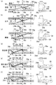
図5は、冷蔵庫のクローザを示し、(a)は扉閉時及び扉開時を示す透視斜視図、(b)は可動側トルク付与部を下方から見上げた状態を示す拡大斜視図と、固定側トルク付与部を示す拡大斜視図である。なお、図5(b)では、可動側トルク付与部と固定側トルク付与部について見る角度を変えて図示している。
図5(a)に示すように、本実施形態におけるクローザ37(回転トルク付与部材)は、断熱箱体10に取り付けられる固定側トルク付与部38と、扉2aに取り付けられる可動側トルク付与部39と、を備えて構成されている。
≪Closer≫
FIG. 5 shows a refrigerator closer, (a) is a perspective view showing when the door is closed and when the door is open, and (b) is an enlarged perspective view showing a state in which the movable side torque applying portion is looked up from below, and a fixed state. It is an expansion perspective view which shows a side torque provision part. In FIG. 5B, the movable side torque applying unit and the fixed side torque applying unit are shown with different angles.
As shown in FIG. 5A, the closer 37 (rotational torque applying member) in this embodiment includes a fixed torque applying portion 38 attached to the heat insulating box 10 and a movable torque applying portion 39 attached to the door 2a. And is configured.

固定側トルク付与部38は、円形のリング部38aと、このリング部38aから径方向外側に延出して当該リング部38aを断熱箱体10にねじ固定する固定部38bと、を有している。また、固定側トルク付与部38は、断熱箱体10から前方に延びる脚部10uの上面に固定されている。   The fixed-side torque applying portion 38 includes a circular ring portion 38a and a fixing portion 38b that extends radially outward from the ring portion 38a and fixes the ring portion 38a to the heat insulating box 10 with screws. . Further, the fixed-side torque applying portion 38 is fixed to the upper surface of the leg portion 10 u extending forward from the heat insulating box 10.

可動側トルク付与部39は、円形のリング部39aと、このリング部39aから径方向外側に延出して当該リング部39aを扉2aの下面にねじ固定する固定部39bと、リング部39aと同軸に配置されて上方に向けて突出する円筒部39cとを有している。円筒部39cは、扉2aの下面から上方に向けて埋め込まれるようにして固定される。なお、図示していないが、脚部10uからは、リング部38a,39a内を挿通し、扉2aを回動自在に支持する軸部が突出して形成されている。   The movable side torque applying portion 39 includes a circular ring portion 39a, a fixing portion 39b that extends radially outward from the ring portion 39a and screws the ring portion 39a to the lower surface of the door 2a, and is coaxial with the ring portion 39a. And a cylindrical portion 39c that protrudes upward. The cylindrical portion 39c is fixed so as to be embedded upward from the lower surface of the door 2a. Although not shown, a shaft portion that protrudes from the leg portion 10u through the ring portions 38a and 39a and rotatably supports the door 2a is formed.

リング部38aとリング部39aは、互いに同軸に配置され、扉2aの自重によって、リング部38aの上面に、リング部39aが当接するように構成されている。   The ring portion 38a and the ring portion 39a are arranged coaxially with each other, and are configured such that the ring portion 39a abuts against the upper surface of the ring portion 38a by the weight of the door 2a.

図5(b)に示すように、固定側トルク付与部38は、リング部38aの上面に、第1傾斜面38c(第1回転トルク付与部)、第2傾斜面38d(第2回転トルク付与部)、第3傾斜面38e(第3回転トルク付与部)及び水平面38f(回転トルク非付与部)が形成されている。固定側トルク付与部38は、第1傾斜面38c、第2傾斜面38d、第3傾斜面38e及び水平面38fが円周方向に沿って順に連続して形成されている。   As shown in FIG. 5 (b), the fixed-side torque applying portion 38 has a first inclined surface 38c (first rotating torque applying portion) and a second inclined surface 38d (second rotating torque applying) on the upper surface of the ring portion 38a. Part), a third inclined surface 38e (third rotational torque applying part) and a horizontal plane 38f (rotating torque non-applying part). The fixed-side torque applying portion 38 is formed with a first inclined surface 38c, a second inclined surface 38d, a third inclined surface 38e, and a horizontal plane 38f successively in order along the circumferential direction.

第1傾斜面38cは、扉2a(図5(a)参照)に対して閉じ方向の回転トルクを発生させるものである。第2傾斜面38dは、扉2aに対して開き方向の回転トルクを発生させるものである。第3傾斜面38eは、扉2aに対して閉じ方向の回転トルクを発生させるものである。水平面38fは、扉2aに対して回転トルクを発生させないものである。第1傾斜面38cが形成される角度範囲と、第2傾斜面38dが形成される角度範囲と、第3傾斜面38eが形成される角度範囲と、水平面38fが形成される角度範囲と、を合わせた角度は、略180°に設定されている。   The first inclined surface 38c generates a rotational torque in the closing direction with respect to the door 2a (see FIG. 5A). The second inclined surface 38d generates a rotational torque in the opening direction with respect to the door 2a. The third inclined surface 38e generates a rotational torque in the closing direction with respect to the door 2a. The horizontal surface 38f does not generate rotational torque with respect to the door 2a. An angle range in which the first inclined surface 38c is formed, an angle range in which the second inclined surface 38d is formed, an angle range in which the third inclined surface 38e is formed, and an angle range in which the horizontal surface 38f is formed. The combined angle is set to approximately 180 °.

また、第2傾斜面38dは、第1傾斜面38c及び第3傾斜面38eよりも傾斜角度が緩やかに(小さく)形成されている。また、リング部38aの上面には、当該リング部38aの軸を中心として点対称となるように、第1傾斜面38c、第2傾斜面38d、第3傾斜面38e及び水平面38fが形成されている。   The second inclined surface 38d is formed with a gentler (smaller) inclination angle than the first inclined surface 38c and the third inclined surface 38e. Further, a first inclined surface 38c, a second inclined surface 38d, a third inclined surface 38e, and a horizontal surface 38f are formed on the upper surface of the ring portion 38a so as to be point-symmetric about the axis of the ring portion 38a. Yes.

可動側トルク付与部39は、リング部39aの下面に、前記したリング部38aと線対称(上下逆さまにした形)となるように、第1傾斜面39d、第2傾斜面39e、第3傾斜面39f及び水平面39gが形成されている。すなわち、前記したリング部38aと逆向きの周方向に沿って順に、第1傾斜面39d(第1回転トルク付与部)、第2傾斜面39e(第2回転トルク付与部)、第3傾斜面39f(第3回転トルク付与部)及び水平面39g(回転トルク非付与部)が形成されている。   The movable-side torque applying portion 39 has a first inclined surface 39d, a second inclined surface 39e, and a third inclined surface on the lower surface of the ring portion 39a so as to be line-symmetrical (upside down) with the ring portion 38a. A surface 39f and a horizontal surface 39g are formed. That is, the first inclined surface 39d (first rotational torque applying unit), the second inclined surface 39e (second rotational torque applying unit), and the third inclined surface in order along the circumferential direction opposite to the ring portion 38a. 39f (third rotational torque applying portion) and a horizontal surface 39g (rotating torque non-applying portion) are formed.

第1傾斜面39dは、扉2aに対して閉じ方向の回転トルクを発生させるものである。第2傾斜面39eは、扉2aに対して開き方向の回転トルクを発生させるものである。第3傾斜面39fは、扉2aに対して閉じ方向の回転トルクを発生させるものである。水平面39gは、扉2aに対してトルクの発生を停止させるものである。   39 d of 1st inclined surfaces generate | occur | produce the rotational torque of a closing direction with respect to the door 2a. The second inclined surface 39e generates rotational torque in the opening direction with respect to the door 2a. The third inclined surface 39f generates rotational torque in the closing direction with respect to the door 2a. The horizontal surface 39g stops the generation of torque for the door 2a.

また、第2傾斜面38d,39eの傾斜角度は、第1傾斜面38c,39d及び第3傾斜面38e、39fの傾斜角度よりも小さくなるように形成されている。また、第1傾斜面38c,39dの傾斜角度は、第3傾斜面38e,39fの傾斜角度と同程度となるように形成されている。第1傾斜面38c,39dの角度範囲は、例えば、15°に設定され、第2傾斜面38d,39eの角度範囲は、例えば、75°に設定され、第3傾斜面38e,39fの角度範囲は、例えば、15°に設定される。   The inclination angles of the second inclined surfaces 38d and 39e are formed to be smaller than the inclination angles of the first inclined surfaces 38c and 39d and the third inclined surfaces 38e and 39f. Further, the inclination angles of the first inclined surfaces 38c and 39d are formed to be approximately the same as the inclination angles of the third inclined surfaces 38e and 39f. The angle range of the first inclined surfaces 38c and 39d is set to, for example, 15 °, the angle range of the second inclined surfaces 38d and 39e is set to, for example, 75 °, and the angle range of the third inclined surfaces 38e and 39f. Is set to 15 °, for example.

このように、本実施形態では、第1傾斜面38cと第1傾斜面39dとで、特許請求の範囲にいう「第1回転トルク付与部」が構成され、第2傾斜面38dと第2傾斜面39eとで、特許請求の範囲にいう「第2回転トルク付与部」が構成され、第3傾斜面38eと第3傾斜面39fとで、特許請求の範囲にいう「第3回転トルク付与部」が構成され、水平面38fと水平面39gとで、特許請求の範囲にいう「回転トルク非付与部」が構成されている。   Thus, in the present embodiment, the first inclined surface 38c and the first inclined surface 39d constitute the “first rotational torque applying portion” as defined in the claims, and the second inclined surface 38d and the second inclined surface 38d. The surface 39e constitutes a “second rotational torque applying portion” as defined in the claims, and the third inclined surface 38e and the third inclined surface 39f constitute the “third rotational torque applying portion” as defined in the claims. The horizontal plane 38f and the horizontal plane 39g constitute a “rotational torque non-applying portion” as defined in the claims.

図6(a)〜(f)は冷蔵庫のクローザの動作説明図である。なお、図6(a)〜(f)は、左側に、クローザ37における、第1傾斜面38c,39d、第2傾斜面38d,39e、第3傾斜面38e,39f及び水平面38f,39gを展開し、また180°の範囲内のみを例に挙げて示し、右側に、クローザ37の斜視図を示している。また、図6(a)〜(f)において、下側に示すものは、本体側つまり固定側であり、上側に示すものは、扉側つまり可動側である。また、図6(a)は、扉2aが閉状態(0°の状態)、図6(b)は、扉2aの開き角度(以下、開角度とする)が15°の状態、図6(c)は、扉2aの開角度が30°の状態、図6(d)は、扉2aの開角度が90°の状態、図6(e)は、扉2aの開角度が105°の状態、図6(e)は、扉2aの開角度が120°の状態である。また、図6(b)〜(f)において、破線で示すものは、図6(a)で示す閉状態(0°の状態)での扉2aの位置を示している。   FIGS. 6A to 6F are operation explanatory views of the refrigerator closer. 6A to 6F, on the left side, the first inclined surfaces 38c and 39d, the second inclined surfaces 38d and 39e, the third inclined surfaces 38e and 39f, and the horizontal surfaces 38f and 39g of the closer 37 are developed. In addition, only a range of 180 ° is shown as an example, and a perspective view of the closer 37 is shown on the right side. 6A to 6F, what is shown on the lower side is the main body side, that is, the fixed side, and what is shown on the upper side is the door side, that is, the movable side. 6 (a) shows a state in which the door 2a is in a closed state (0 ° state), FIG. 6 (b) shows a state in which the opening angle of the door 2a (hereinafter referred to as an opening angle) is 15 °, and FIG. c) is a state where the opening angle of the door 2a is 30 °, FIG. 6 (d) is a state where the opening angle of the door 2a is 90 °, and FIG. 6 (e) is a state where the opening angle of the door 2a is 105 °. FIG. 6E shows a state in which the opening angle of the door 2a is 120 °. 6 (b) to 6 (f), the broken line indicates the position of the door 2a in the closed state (0 ° state) shown in FIG. 6 (a).

図6(a)に示すように、扉2aが閉状態では、本体側(固定側)の第1傾斜面38cに、扉側(可動側)の第1傾斜面39dが当接する。なお、閉状態とは、扉2aが閉まろうとしている状態ではなく、現に閉まっている状態を意味する(扉2bについても同様)。この場合、扉2aの自重Gによって、第1傾斜面38cが、第1傾斜面39d上を滑り下りることで、矢印F1で示す閉じ力が発生する。ここでの閉じ力とは、扉2aを閉じる方向(閉じ方向)に動作させる回転トルク(斜視図の矢印W1参照)を意味している。このように、扉2aを完全に閉じ切る前に、扉2aに対して閉じ方向に回転トルクを発生させることによって、いわゆる半ドアを防止するようになっている。   As shown in FIG. 6A, when the door 2a is in the closed state, the first inclined surface 39d on the door side (movable side) contacts the first inclined surface 38c on the main body side (fixed side). The closed state means not the state where the door 2a is about to close but the state where it is actually closed (the same applies to the door 2b). In this case, the first inclined surface 38c slides down on the first inclined surface 39d by the dead weight G of the door 2a, thereby generating a closing force indicated by the arrow F1. The closing force here means a rotational torque (see an arrow W1 in the perspective view) that operates the door 2a in the closing direction (closing direction). Thus, before the door 2a is completely closed, a so-called half door is prevented by generating a rotational torque in the closing direction with respect to the door 2a.

また、扉2aが閉状態では、本体側(固定側)の第1傾斜面38cと扉側(可動側)の第1傾斜面39dとが部分的に当接している。すなわち、第1傾斜面38cの全面と第1傾斜面39dの全面とが当接するのではなく、第1傾斜面38cの上部と第1傾斜面39dの下部とが当接するようになっている。これにより、扉2aに対して常に閉じ力F1が発生するので、外的要因などによって扉2aが不用意に開いてしまうのを防止することができる。   When the door 2a is closed, the first inclined surface 38c on the main body side (fixed side) and the first inclined surface 39d on the door side (movable side) are in partial contact. That is, the entire surface of the first inclined surface 38c and the entire surface of the first inclined surface 39d are not in contact with each other, but the upper portion of the first inclined surface 38c and the lower portion of the first inclined surface 39d are in contact with each other. Thereby, since the closing force F1 is always generated with respect to the door 2a, it is possible to prevent the door 2a from being inadvertently opened due to an external factor or the like.

図6(b)に示すように、扉2aがψ1(第1所定角度/例えば、15°)開いた状態では、本体側(固定側)の第1傾斜面38cと第2傾斜面38dとの境界の頂点38sに、扉側(可動側)の第1傾斜面39dと第2急斜面39eとの境界の頂点39sが当接する。この場合、扉2aの自重Gが作用したとしても、扉2aを閉じる閉じ力(閉じ方向の回転トルク)も、扉2aを開く開き力(開き方向の回転トルク)も発生せず、扉2aは、開き角度が15°の位置で停止した状態を維持する。   As shown in FIG. 6B, when the door 2a is opened at ψ1 (first predetermined angle / for example, 15 °), the first inclined surface 38c and the second inclined surface 38d on the main body side (fixed side) The vertex 39s at the boundary between the first inclined surface 39d on the door side (movable side) and the second steep slope 39e abuts on the vertex 38s at the boundary. In this case, even if the dead weight G of the door 2a acts, neither the closing force (rotating torque in the closing direction) for closing the door 2a nor the opening force (rotating torque in the opening direction) for opening the door 2a is generated. The state where the opening angle is stopped at the position of 15 ° is maintained.

図6(c)に示すように、扉2aが30°開いた状態では、本体側(固定側)の第2傾斜面38dに、扉側(可動側)の第2傾斜面39eが当接する。この場合、扉2aの自重Gによって、第2傾斜面39eが、第2傾斜面38d上を滑り下りることで、矢印F2で示す開き力が発生する。ここでの開き力とは、扉2aを開く方向(開き方向)に動作させる回転トルク(斜視図の矢印W2参照)を意味している。   As shown in FIG. 6C, when the door 2a is opened by 30 °, the second inclined surface 39e on the door side (movable side) abuts on the second inclined surface 38d on the main body side (fixed side). In this case, the opening force shown by the arrow F2 is generated by the second inclined surface 39e sliding down on the second inclined surface 38d by the dead weight G of the door 2a. Here, the opening force means a rotational torque (see an arrow W2 in the perspective view) that operates the door 2a in the opening direction (opening direction).

図6(d)に示すように、扉2aがψ2(第2所定角度/例えば、90°)開いた状態では、本体側(固定側)の第2傾斜面38dの全面に、扉側(可動側)の第2傾斜面39eの全面が当接する。図6(c)から図6(d)に至る過程において、第2傾斜面38dと第傾斜面39eとの摩擦力によって開き力F2が徐々に低下し、扉2aが90°開いたところで停止する。このように、第2傾斜面38d,39eによって、扉2aを90°開いた位置で停止させることで、庫内の物の出し入れがし易くなる。 As shown in FIG. 6D, in the state where the door 2a is opened at ψ2 (second predetermined angle / 90 °, for example), the door side (movable) is placed on the entire surface of the second inclined surface 38d on the main body side (fixed side). The entire surface of the second inclined surface 39e comes into contact. In the process from FIG. 6C to FIG. 6D, the opening force F2 gradually decreases due to the frictional force between the second inclined surface 38d and the second inclined surface 39e, and stops when the door 2a opens 90 °. To do. As described above, the door 2a is stopped at a position opened 90 ° by the second inclined surfaces 38d and 39e, thereby making it easy to take in and out the items in the warehouse.

図6(e)に示すように、扉2aの開く勢いが強すぎて、扉2aが105°開いたとしても、本体側(固定側)の第3傾斜面38eに、扉側(可動側)の第1傾斜面39dが当接し、また本体側(固定側)の第1傾斜面38cに、扉側(可動側)の第3傾斜面39fが当接する。この場合、扉2aの自重Gに逆らって、第1傾斜面39dが、第3傾斜面38e上を登ろうとし、また第3傾斜面39fが、第1傾斜面38c上を登ろうとするが、次第に開き力(開き方向の回転トルク)が無くなり、矢印F3で示す閉じ力が発生する。ここでの閉じ力とは、扉2aを閉じる方向(閉じ方向)に動作させる回転トルク(斜視図の矢印W3参照)を意味している。このように、第3傾斜面38e,39fを設けることで、扉2aが開き過ぎないように制動することができる。   As shown in FIG. 6 (e), even if the door 2a opens too much and the door 2a opens 105 °, the door side (movable side) is placed on the third inclined surface 38e on the main body side (fixed side). The first inclined surface 39d abuts, and the door side (movable side) third inclined surface 39f abuts on the main body side (fixed side) first inclined surface 38c. In this case, against the dead weight G of the door 2a, the first inclined surface 39d tries to climb on the third inclined surface 38e, and the third inclined surface 39f tries to climb on the first inclined surface 38c. The opening force (rotational torque in the opening direction) gradually disappears, and a closing force indicated by an arrow F3 is generated. The closing force here means a rotational torque (see an arrow W3 in the perspective view) that operates the door 2a in the closing direction (closing direction). As described above, by providing the third inclined surfaces 38e and 39f, it is possible to brake the door 2a so as not to open too much.

図6(f)に示すように、扉2aがψ3(第3所定角度/例えば、120°)開いた状態では、本体側(固定側)の水平面38fに、扉側(可動側)の頂点39sが当接し、また本体側(固定側)の頂点38sに、扉側(可動側)の水平面39gが当接する。この場合、水平面38fと頂点39sとが当接し、頂点38sと水平面39gとが当接するので、扉2aの自重Gが作用しても、扉2aを閉じる閉じ力(閉じ方向の回転トルク)も、扉2aを開く開き力(開き方向の回転トルク)も発生せず、扉2aは、開いた位置で停止した状態を維持する。このように、扉2aを90°を超えて大きく開いた状態を維持できるので、使い勝手を向上させることができる。   As shown in FIG. 6 (f), when the door 2a is opened at ψ3 (third predetermined angle / 120 °, for example), a vertex 39s on the door side (movable side) is placed on the horizontal surface 38f on the main body side (fixed side). Further, the door (movable side) horizontal surface 39g contacts the main body side (fixed side) vertex 38s. In this case, the horizontal plane 38f and the apex 39s come into contact with each other, and the apex 38s and the horizontal plane 39g come into contact with each other. An opening force (rotational torque in the opening direction) for opening the door 2a is not generated, and the door 2a maintains a stopped state at the opened position. Thus, since the door 2a can be maintained in a state where it is greatly opened beyond 90 °, usability can be improved.

このように、本実施形態におけるクローザ37は、例えば開角度15°未満において、第1傾斜面38c,39dによって閉じ方向の回転トルク(図6(a)の閉じ力F1参照)を発生させている。また、クローザ37は、例えば開角度15°以上90°未満において、第2傾斜面38d,39eによって開き方向の回転トルク(図6(c)の開き力F2参照)を発生させている。また、クローザ37は、例えば開角度90°以上105°未満において、第3傾斜面38e,39fによって閉じ方向の回転トルク(図6(e)の閉じ力F3参照)を発生させている。また、クローザ37は、例えば開角度が105°以上において、水平面38f,39gによる非回転トルク(図6(f)参照)が発揮されるようになっている。つまり、本実施形態のクローザ37では、閉じ力F1を付与することで半ドアを防止し、また開き力F2を付与することで開扉装置60によって開かれたときに庫内の物を出し入れし易い位置に扉2a,2bを解放することができ、また閉じ力F3を付与することで、扉2aの開き過ぎを抑制することができ、また回転トルク非付与部を設けることで、扉2aをさらに大きく開いた状態を維持して使い勝手を向上することが可能になる。   As described above, the closer 37 according to the present embodiment generates the rotational torque in the closing direction (see the closing force F1 in FIG. 6A) by the first inclined surfaces 38c and 39d at an opening angle of less than 15 °, for example. . Further, the closer 37 generates a rotational torque in the opening direction (see the opening force F2 in FIG. 6C) by the second inclined surfaces 38d and 39e at an opening angle of 15 ° or more and less than 90 °, for example. Further, the closer 37 generates a rotational torque in the closing direction (see the closing force F3 in FIG. 6E) by the third inclined surfaces 38e and 39f, for example, at an opening angle of 90 ° to less than 105 °. Further, the closer 37 is configured to exhibit non-rotating torque (see FIG. 6F) by the horizontal surfaces 38f and 39g, for example, when the open angle is 105 ° or more. That is, in the closer 37 according to the present embodiment, the closing force F1 is applied to prevent the half door, and the opening force F2 is applied to allow the inside of the cabinet to be taken in and out when opened. The doors 2a and 2b can be released at easy positions, and by applying the closing force F3, the door 2a can be prevented from opening too much, and the rotational torque non-applying portion is provided to Further, it is possible to improve the usability by maintaining a state of being opened wide.

なお、クローザ37は、左右の扉2a,2bで互いに対称の形状となっていること以外は同一の構造を有しているので、ここでは左側の扉2aのクローザについてのみ詳細に説明して右側の扉2bのクローザについてはその記載を省略する。   The closer 37 has the same structure except that the left and right doors 2a and 2b are symmetrical to each other, so only the closer of the left door 2a will be described in detail here. The description of the closer of the door 2b is omitted.

≪開扉装置≫
次に、本実施形態における開扉装置60について詳細に説明する。
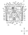
図7は、本実施形態の開扉装置の斜視図である。図8は、開扉装置の平面図である。
以下の開扉装置60の説明における前後上下左右の方向は、この開扉装置60が取り付けられた冷蔵庫1(図2及び図3参照)の前後上下左右に対応している。
≪Opening device≫
Next, the door opening device 60 in the present embodiment will be described in detail.
FIG. 7 is a perspective view of the door opening device of the present embodiment. FIG. 8 is a plan view of the door opening device.
The front, rear, up, down, left, and right directions in the following description of the door opening device 60 correspond to the front, back, up, down, left, and right of the refrigerator 1 (see FIGS. 2 and 3) to which the door opening device 60 is attached.

図7及び図8に示すように、本実施形態の開扉装置60は、下半体であるケース62と上半体であるカバー69とで形成されるハウジング内に、モータ82と、減速歯車列83と、大歯車76と、一対の間欠駆動歯車78a,78bと、一対の突出部材61a,61bと、を主に備えて構成されている。   As shown in FIGS. 7 and 8, the door opening device 60 of the present embodiment includes a motor 82 and a reduction gear in a housing formed by a case 62 as a lower half and a cover 69 as an upper half. The main assembly includes a row 83, a large gear 76, a pair of intermittent drive gears 78a and 78b, and a pair of projecting members 61a and 61b.

ちなみに、図7及び図8に示すように、突出部材61a,61bが、ケース62内からその外側に向けて突出していない状態を、開扉装置60の「初期状態」と称することがある。また、「初期状態」の開扉装置60における、減速歯車列83、大歯車76、間欠駆動歯車78a,78b、及び突出部材61a,61bの位置を、それらの「原点位置」と称することがある。また、本実施形態では、減速歯車列83、大歯車76、間欠駆動歯車78a、回転板73a、および連結板65aによって、扉2a側での特許請求の範囲にいう「ギヤ部」が構成されている。また、本実施形態では、減速歯車列83、大歯車76、間欠駆動歯車78b、回転板73b、および連結板65bによって、扉2b側での特許請求の範囲にいう「ギヤ部」が構成されている。   Incidentally, as shown in FIGS. 7 and 8, a state in which the protruding members 61 a and 61 b do not protrude from the inside of the case 62 toward the outside thereof may be referred to as an “initial state” of the door opening device 60. The positions of the reduction gear train 83, the large gear 76, the intermittent drive gears 78a and 78b, and the protruding members 61a and 61b in the opening device 60 in the “initial state” may be referred to as “origin positions”. . In the present embodiment, the reduction gear train 83, the large gear 76, the intermittent drive gear 78a, the rotating plate 73a, and the connecting plate 65a constitute a “gear portion” as defined in the claims on the door 2a side. Yes. In the present embodiment, the reduction gear train 83, the large gear 76, the intermittent drive gear 78b, the rotating plate 73b, and the connecting plate 65b constitute a “gear portion” in the claims on the door 2b side. Yes.

<モータ>
モータ82は回転モータであって、その回転軸が正逆両方向に回転するものであればその種類は特に制限はない。本実施形態でのモータ82としては、例えばブラシ式の直流モータであって、端子に印加する電圧の極性を反転することで正転方向と逆転方向との両方向に回転することができるものを想定している。
<Motor>
The type of the motor 82 is not particularly limited as long as the rotary shaft rotates in both forward and reverse directions. As the motor 82 in the present embodiment, for example, a brush type direct current motor, which can rotate in both the forward direction and the reverse direction by reversing the polarity of the voltage applied to the terminal is assumed. doing.

<減速歯車列>
減速歯車列83は、モータ82の回転を減速しつつ、その動力を大歯車76に伝達するものである。
本実施形態での減速歯車列83は、ウォームギヤ84と、ウォームホイール85と、第二の歯車87と、第三の大歯車88aと、第三の小歯車88bと、第四の大歯車90aと、第四の小歯車90bと、を備えている。
<Reduction gear train>
The reduction gear train 83 transmits the power to the large gear 76 while reducing the rotation of the motor 82.
The reduction gear train 83 in this embodiment includes a worm gear 84, a worm wheel 85, a second gear 87, a third large gear 88a, a third small gear 88b, and a fourth large gear 90a. And a fourth small gear 90b.

図9は、図8のC−C断面図である。
図8及び図9に示すように、ウォームギヤ84は、モータ82の回転軸に設けられ、第一の歯車であるウォームホイール85と噛み合っている。平歯車である第二の歯車87はウォームホイール85と一体に設けられ、ウォームホイール85と第二の歯車87は共にウォームホイール軸86のまわりに回転自在に軸支されている。
9 is a cross-sectional view taken along the line CC of FIG.
As shown in FIGS. 8 and 9, the worm gear 84 is provided on the rotating shaft of the motor 82 and meshes with the worm wheel 85 that is the first gear. The second gear 87, which is a spur gear, is provided integrally with the worm wheel 85, and both the worm wheel 85 and the second gear 87 are rotatably supported around the worm wheel shaft 86.

第二の歯車87は、第三の大歯車88a(図8参照)と噛み合い、この第三の大歯車88aは、第三の小歯車88b(図8参照)と一体になって第三の支軸89(図8参照)のまわりに回転自在に軸支されている。また、第三の小歯車88b(図8参照)は、第四の大歯車90aと噛み合っている。この第四の大歯車90aは、第四の小歯車90bと一体になって第四の支軸91のまわりに回転自在に軸支されている。また、第四の小歯車90bは、大歯車76の後記する歯76A,76B(図10参照)と噛み合っている。
つまり、減速歯車列83は、前記のように、モータ82の回転力を減速しつつ、大歯車76に伝達する構成となっている。
The second gear 87 meshes with the third large gear 88a (see FIG. 8), and this third large gear 88a is integrated with the third small gear 88b (see FIG. 8) to form a third support. It is rotatably supported around a shaft 89 (see FIG. 8). Further, the third small gear 88b (see FIG. 8) meshes with the fourth large gear 90a. The fourth large gear 90a is pivotally supported around the fourth support shaft 91 integrally with the fourth small gear 90b. Further, the fourth small gear 90b meshes with teeth 76A and 76B (see FIG. 10) described later of the large gear 76.
That is, the reduction gear train 83 is configured to transmit the rotational force of the motor 82 to the large gear 76 while reducing the rotational force as described above.

モータ82を回転させた際の、それぞれの歯車の回転方向の一例を図8の矢印にて示す。
ウォームギヤ84の回転方向は、一例としてウォームギヤ84に設けられた螺旋状の歯がこれと噛み合うウォームホイール85を、図8で表す平面視で左回りに回転させる方向を実線矢印で示している。例えばウォームギヤ84の歯が、一般的なネジとは逆の左ネジの螺旋である場合には、ウォームギヤ84の先端側から見てモータ82を時計回りに回転すればよく、本実施形態においてはこのような回転方向を「正転方向」と称するものとする。
An example of the rotation direction of each gear when the motor 82 is rotated is indicated by arrows in FIG.
As an example, the rotation direction of the worm gear 84 is indicated by a solid arrow in the direction in which the worm wheel 85 provided on the worm gear 84 meshes with the helical teeth counterclockwise in a plan view shown in FIG. For example, if the teeth of the worm gear 84 are a left-handed spiral that is the opposite of a general screw, the motor 82 may be rotated clockwise as viewed from the front end side of the worm gear 84. Such a rotation direction is referred to as a “forward rotation direction”.

モータ82に印加する電圧の極性を逆にすることで、ウォームギヤ84を逆方向に回転した場合を破線矢印で図示しており、本実施形態においてはこのような回転方向を「逆転方向」と称するものとする。
なお言うまでも無く、「正転」「逆転」というのは本実施形態の説明の便宜上のことであり、かかる表現に限定されるものではない。
A case where the worm gear 84 is rotated in the reverse direction by reversing the polarity of the voltage applied to the motor 82 is indicated by a broken-line arrow. In this embodiment, such a rotation direction is referred to as a “reverse direction”. Shall.
Needless to say, “forward rotation” and “reverse rotation” are for convenience of description of the present embodiment, and are not limited to such expressions.

このような減速歯車列83は、図8に示すように、大歯車76よりも背面寄りで(後方寄りで)、かつケース62の左右中央近傍に配置されている。また、モータ82は減速歯車列83に隣接してケース62の背面(後面)に沿って配置されている。また、減速歯車列83に対してモータ82の対面側には、図示しない配線コネクタや配線が配置される配線スペース81が設けられている。つまり、モータ82と減速歯車列83と配線スペース81とは、ケース62の背面(後面)に沿って並列する構成となっている。
なお、本実施形態でのモータ82は、減速歯車列83に対して図8で表す平面視で左側面寄りに配置したが、本発明はこのような配置に限定されるものではなく、右側面寄りに、又は中央寄りに配置することもできる。
As shown in FIG. 8, such a reduction gear train 83 is disposed closer to the back surface (closer to the rear) than the large gear 76 and in the vicinity of the center of the left and right sides of the case 62. Further, the motor 82 is disposed along the back surface (rear surface) of the case 62 adjacent to the reduction gear train 83. A wiring space 81 in which wiring connectors and wiring (not shown) are arranged is provided on the opposite side of the motor 82 with respect to the reduction gear train 83. That is, the motor 82, the reduction gear train 83, and the wiring space 81 are configured in parallel along the back surface (rear surface) of the case 62.
Although the motor 82 in this embodiment is arranged closer to the left side in the plan view shown in FIG. 8 with respect to the reduction gear train 83, the present invention is not limited to such an arrangement, and the right side It can also be arranged closer to the center or closer to the center.

<大歯車>
図10は、開扉装置の大歯車と間欠駆動歯車とを示す斜視図である。
図10に示すように、大歯車76の外周において角度θ0の範囲には、厚さ方向の全幅において歯車の歯76Aが設けられている。角度θ0の範囲外においては、厚さ方向にケース62に近接した側、すなわち図示下方略1/2にのみ歯76Aと連続した一連の歯76Bが全周にわたって設けられている。そして、図示上方略1/2には歯は設けられておらず、歯76Bの歯底円と同じか、又は歯底円よりも小さい円筒状の摺動面76Cが設けられている。摺動面76Cと全幅に設けられた歯76Aとの境界には、摺動面76Cよりも内周側に凹んだ切欠部76Dが設けられている。
<Large gear>
FIG. 10 is a perspective view showing a large gear and an intermittent drive gear of the door opening device.
As shown in FIG. 10, gear teeth 76A are provided in the range of the angle θ0 on the outer periphery of the large gear 76 over the entire width in the thickness direction. Outside the range of the angle θ0, a series of teeth 76B that are continuous with the teeth 76A are provided over the entire circumference only on the side close to the case 62 in the thickness direction, that is, approximately on the lower side in the figure. In the upper half of the figure, no tooth is provided, and a cylindrical sliding surface 76C that is the same as or smaller than the root circle of the tooth 76B is provided. At the boundary between the sliding surface 76C and the teeth 76A provided at the full width, a notch 76D that is recessed to the inner peripheral side from the sliding surface 76C is provided.

大歯車76の歯76Aの対面側には、大歯車ストッパ76Eが設けられている。大歯車76が前記の原点位置から角度θ6回転すると、大歯車ストッパ76Eは大歯車76と共に角度θ6回転してカバーストッパ71に当接する。
ちなみに、カバーストッパ71は、図9に示すように、カバー69から大歯車76に向けて内側に凸となるように形成された切片である。
このメカストッパとしてのカバーストッパ71によって、大歯車76の回転角度範囲は、原点位置から±θ6までに制限されることとなる。
A large gear stopper 76E is provided on the opposite side of the teeth 76A of the large gear 76. When the large gear 76 rotates by an angle θ6 from the origin position, the large gear stopper 76E rotates by an angle θ6 together with the large gear 76 and comes into contact with the cover stopper 71.
Incidentally, as shown in FIG. 9, the cover stopper 71 is a section formed so as to protrude inward from the cover 69 toward the large gear 76.
The rotational angle range of the large gear 76 is limited to ± θ6 from the origin position by the cover stopper 71 as the mechanical stopper.

<間欠駆動歯車>
図11は、図8のD−D断面図である。
図10及び図11に示すように、間欠駆動歯車78a(第一の間欠駆動歯車)は、回転板中心74aのまわりに回動自在に軸支され、間欠駆動歯車78b(第二の間欠駆動歯車)は、回転板中心74bのまわりに回動自在に軸支されている。
<Intermittent drive gear>
11 is a cross-sectional view taken along the line DD of FIG.
As shown in FIGS. 10 and 11, the intermittent drive gear 78a (first intermittent drive gear) is pivotally supported around the rotating plate center 74a, and the intermittent drive gear 78b (second intermittent drive gear) is supported. ) Is pivotally supported around the rotating plate center 74b.

間欠駆動歯車78a,78bは、大歯車76の歯76A(図10参照)と噛み合う歯79a,79b(図10参照)と、外周側に一部突出するストッパ部80a,80b(図10参照)とが形成されている。このストッパ部80a,80bが大歯車76に近接する向きに間欠駆動歯車78a,78bを配置した際には、大歯車76と間欠駆動歯車78a,78bとは歯車としては噛み合っておらず、ストッパ部80a,80bは大歯車76の摺動面76C(図10参照)と摺動自在となっている。   The intermittent drive gears 78a and 78b include teeth 79a and 79b (see FIG. 10) that mesh with the teeth 76A (see FIG. 10) of the large gear 76, and stopper portions 80a and 80b (see FIG. 10) that partially protrude on the outer peripheral side. Is formed. When the intermittent drive gears 78a and 78b are arranged in a direction in which the stopper portions 80a and 80b are close to the large gear 76, the large gear 76 and the intermittent drive gears 78a and 78b are not meshed with each other as the gear. 80a and 80b are slidable on the sliding surface 76C (see FIG. 10) of the large gear 76.

また、ストッパ部80a,80bの先端面は、摺動面76Cの周面と合致した円弧状の凹面となっている。つまり、ストッパ部80a,80bの先端面(凹面)と、摺動面76Cの周面とは相互に嵌り合い、摺動面76Cの周面上で移動する間欠駆動歯車78a,78bは、回転しようとしてもロックした状態となって回転しない。
この状態で大歯車76が回動しても、間欠駆動歯車78a,78bのストッパ部80a,80bの先端面(凹面)は大歯車76の摺動面76Cを摺動するだけなので間欠駆動歯車78a,78bは回転しない。
Further, the tip surfaces of the stopper portions 80a and 80b are arcuate concave surfaces that coincide with the peripheral surface of the sliding surface 76C. That is, the distal end surfaces (concave surfaces) of the stopper portions 80a and 80b and the peripheral surface of the sliding surface 76C are fitted to each other, and the intermittent drive gears 78a and 78b that move on the peripheral surface of the sliding surface 76C are rotated. Even if it is locked, it will not rotate.
Even if the large gear 76 rotates in this state, the tip surfaces (concave surfaces) of the stopper portions 80a and 80b of the intermittent drive gears 78a and 78b only slide on the sliding surface 76C of the large gear 76, so that the intermittent drive gear 78a. 78b do not rotate.

図10に示すように、大歯車76の角度θ0の範囲に対して間欠駆動歯車78a,78bを対称に配置した場合を、ここでは大歯車76の「原点位置」と称することとする。なお、「原点位置」とは、点ではなく、幅を持つものである。この「原点位置」において、大歯車76に設けられた切欠部76Dから、ストッパ部80a,80bのうち切欠部76Dに近接した側の端部であるストッパ端部80Aa,80Abまでの角度をθ2とする。
そうすると、「原点位置」から時計回り、ないし反時計回りにそれぞれ角度θ2の範囲で大歯車76が回転する場合には、間欠駆動歯車78a,78bは回転駆動することなくロックした状態を保つ。
As shown in FIG. 10, the case where the intermittent drive gears 78a and 78b are arranged symmetrically with respect to the range of the angle θ0 of the large gear 76 is referred to as the “origin position” of the large gear 76 here. The “origin position” is not a point but a width. At this “origin position”, the angle from the notch 76D provided on the large gear 76 to the stopper ends 80Aa and 80Ab that are the ends of the stoppers 80a and 80b on the side close to the notch 76D is θ2. To do.
Then, when the large gear 76 rotates clockwise or counterclockwise from the “origin position” within the range of the angle θ2, the intermittent drive gears 78a and 78b are kept locked without being driven to rotate.

大歯車76の原点位置からの回転角度がθ2を超えると、摺動面76Cよりも凹んでいる切欠部76Dの内側にストッパ端部80Aa,80Abが入り込むことで間欠駆動歯車78a,78bが回動可能となる。これにより大歯車76の歯76Aと間欠駆動歯車78a,78bの歯79a,79bとが順次噛み合う。そして、大歯車76は、間欠駆動歯車78a,78bにトルクを伝達しつつ間欠駆動歯車78a,78bを回転駆動する。
そして、後記するように、モータ82からの駆動力は、大歯車76の回転方向が時計方向なのか反時計方向なのかに応じて、間欠駆動歯車78a,78bのいずれかに伝達されることとなる。
When the rotation angle of the large gear 76 from the origin position exceeds θ2, the stopper driving portions 80Aa and 80Ab enter the inside of the notch 76D that is recessed from the sliding surface 76C, so that the intermittent drive gears 78a and 78b rotate. It becomes possible. As a result, the teeth 76A of the large gear 76 and the teeth 79a and 79b of the intermittent drive gears 78a and 78b are sequentially meshed with each other. The large gear 76 rotates the intermittent drive gears 78a and 78b while transmitting torque to the intermittent drive gears 78a and 78b.
As will be described later, the driving force from the motor 82 is transmitted to one of the intermittent drive gears 78a and 78b depending on whether the rotation direction of the large gear 76 is clockwise or counterclockwise. Become.

<回転板及び連結板>
図8及び図11に示すように、開扉装置60は、間欠駆動歯車78a,78bからの駆動力を突出部材61a,61bに伝達する、一対の回転板73a,73bと、一対の連結板65a,65bと、を備えている。
<Rotating plate and connecting plate>
As shown in FIGS. 8 and 11, the opening device 60 includes a pair of rotating plates 73a and 73b and a pair of connecting plates 65a that transmit the driving force from the intermittent drive gears 78a and 78b to the protruding members 61a and 61b. , 65b.

回転板73aは、間欠駆動歯車78aと一体になって回転板中心74aのまわりに回転自在に軸支され、回転板73bは、間欠駆動歯車78bと一体になって回転板中心74bのまわりに回転自在に軸支されている。
これらの回転板73a,73b及び連結板65a,65bは、図8及び図11に示すように、開扉装置60内で左右対称の形状となっていること以外は同一の構造を有しているので、ここでは左側の回転板73a及び連結板65aについてのみ詳細に説明して右側の回転板73b及び連結板65bについてはその記載を省略する。
The rotating plate 73a is pivotally supported around the rotating plate center 74a integrally with the intermittent driving gear 78a, and the rotating plate 73b rotates around the rotating plate center 74b integrally with the intermittent driving gear 78b. It is supported freely.
These rotating plates 73a and 73b and connecting plates 65a and 65b have the same structure except that they are symmetrical in the door opening device 60 as shown in FIGS. Therefore, only the left rotation plate 73a and the connection plate 65a will be described in detail here, and the description of the right rotation plate 73b and the connection plate 65b will be omitted.

図12は、開扉装置の回転板と連結板とを示す平面図である。
図12に示すように、回転板73a周囲には、連結板65aの歯101A,101B,101C,101D,101E,101F,101G,101H,101J,101K,101M,101N,101P(合計歯数13/以下、すべてをまとめて言う場合には101A〜101Pと略記)に噛み合う歯102a,102b,102c,102d,102e,102f,102g,102h,102j,102k,102m,102n,102p,102q(合計歯数14/以下、すべてをまとめて言う場合には101a〜102qと略記)が形成されている。
FIG. 12 is a plan view showing a rotating plate and a connecting plate of the door opening device.
As shown in FIG. 12, around the rotating plate 73a, teeth 101A, 101B, 101C, 101D, 101E, 101F, 101G, 101H, 101J, 101K, 101M, 101N, 101P (total number of teeth 13 / Hereinafter, the teeth 102a, 102b, 102c, 102d, 102e, 102f, 102g, 102h, 102j, 102k, 102m, 102n, 102p, and 102q (total number of teeth) meshed with the teeth 102A, 102b, 102c, 102d, 102e, 102f, 102g 14 / below, abbreviated as 101a to 102q when all are collectively referred to.

回転板73aの歯102a〜102qは、図12の平面視で回転板中心74aを中心にして右まわりで、この回転板中心74aから徐々に半径を拡大するよう形成されている。
更に具体的には、回転板73aに設けられた歯102aから歯102qまでの噛み合いピッチ円半径を、図12に示すraからrqとした場合に(aからqはアルファベット順に並ぶところ図中、rbからrpは図示省略)、ra<rb<rc<rd<re<rf<rg<rh<rj<rk<rm<rn<rp<rqの関係式を満たしている。
なお、回転板73aの歯102a〜102qの歯列が描く曲線は、アルキメデス螺旋、双曲螺旋、インボリュート曲線等とすることができるが、前記関係式を満足していれば、これらに限定されるものではない。
The teeth 102a to 102q of the rotating plate 73a are formed so as to gradually increase in radius from the rotating plate center 74a clockwise around the rotating plate center 74a in the plan view of FIG.
More specifically, when the meshing pitch circle radius from the teeth 102a to the teeth 102q provided on the rotating plate 73a is represented by ra to rq shown in FIG. 12 (where a to q are arranged in alphabetical order, rb To rp are not shown), and ra <rb <rc <rd <re <rf <rg <rh <rj <rk <rm <rn <rp <rq.
The curve drawn by the teeth 102a to 102q of the rotating plate 73a can be an Archimedean spiral, a hyperbolic spiral, an involute curve, or the like, but is limited to these as long as the relational expression is satisfied. It is not a thing.

連結板65aは、図7及び図8に示すように、回転板73aの左側(ケース62の左右方向外側)に配置されている。
また、連結板65aは、略三角形状をなしており、第一の辺である左側面の一辺にはガイドレール66aと互いに摺動自在に嵌合する凹部ないしは凸部を備えている。また、第二の辺である前面側の一辺には、突出部材61aの後端部が接合されている。また、残りの第3の辺には、回転板73aが回転する際に、その歯102a〜102q(図12参照)と噛み合う歯101A〜101P(図12参照)が形成されている。つまり、図12に示すように、回転板73aの歯102a〜102qが回転板中心74aから徐々に半径を拡大するよう形成されているので、連結板65aの歯101A〜101Pの歯列は、前方から後方に向かうに従って、回転板73aの左側(ケース62の左右方向外側)に向かうように傾斜するテーパ状になっている。
As shown in FIGS. 7 and 8, the connecting plate 65a is disposed on the left side of the rotating plate 73a (outside in the left-right direction of the case 62).
The connecting plate 65a has a substantially triangular shape, and has a concave portion or a convex portion that is slidably fitted to the guide rail 66a on one side of the left side that is the first side. Further, the rear end portion of the protruding member 61a is joined to one side of the front surface that is the second side. Further, teeth 101A to 101P (see FIG. 12) that mesh with the teeth 102a to 102q (see FIG. 12) when the rotating plate 73a rotates are formed on the remaining third side. That is, as shown in FIG. 12, since the teeth 102a to 102q of the rotating plate 73a are formed so as to gradually increase in radius from the rotating plate center 74a, the tooth row of the teeth 101A to 101P of the connecting plate 65a As it goes from the rear to the rear, the taper is inclined so as to go to the left side of the rotating plate 73a (outside in the left-right direction of the case 62).

回転板73aに設けられた歯102a〜102qは、連結板65aに設けられた歯101A〜101Pの前方と後方とを挟んで噛み合うので、回転板73aの歯数は連結板65aの歯数よりも1つ多く、前記したように、回転板73aの歯数は14、連結板65aの歯数は13となっている。
なお、回転板73aの歯数、及び連結板65aの歯数は、これら14及び13に限定されるものではないが、駆動側である回転板73aの歯数は、従動側である連結板65aの歯数よりも1つ多く設けることが望ましい。このように回転板73a及び連結板65aの歯数を設定することで、回転板73aの歯は、連結板65aの歯を常に両側から挟んで噛み合うこととなる。これにより回転板73aの時計回り及び反時計まわりの両方向の回転動作が安定し、回転板73aから連結板65aへの駆動力の伝達が効率よく行われることとなる。
The teeth 102a to 102q provided on the rotating plate 73a mesh with the front and rear sides of the teeth 101A to 101P provided on the connecting plate 65a, so that the number of teeth of the rotating plate 73a is larger than the number of teeth of the connecting plate 65a. One more, as described above, the number of teeth of the rotating plate 73a is 14, and the number of teeth of the connecting plate 65a is 13.
The number of teeth of the rotating plate 73a and the number of teeth of the connecting plate 65a are not limited to 14 and 13, but the number of teeth of the rotating plate 73a on the driving side is the connecting plate 65a on the driven side. It is desirable to provide one more than the number of teeth. By setting the number of teeth of the rotating plate 73a and the connecting plate 65a in this way, the teeth of the rotating plate 73a are always meshed with the teeth of the connecting plate 65a sandwiched from both sides. As a result, the clockwise and counterclockwise rotation operations of the rotating plate 73a are stabilized, and the driving force is efficiently transmitted from the rotating plate 73a to the connecting plate 65a.

本実施形態での回転板73aは、扉2a(図5参照)を開放する際に、図12の平面視で反時計回りに回転する。
図12に示すように、回転板73aの内周側の歯102aと歯102bとの間に、連結板65aの前端側の歯101Aが噛み合っている。この図12に示す回転板73a及び連結板65aの状態では、後記するように、突出部材61aが開扉装置60のケース62に引き込んだ状態となるので、図12に示す回転板73a及び連結板65aの位置は、前記の「原点位置」となる。
The rotating plate 73a in the present embodiment rotates counterclockwise in the plan view of FIG. 12 when the door 2a (see FIG. 5) is opened.
As shown in FIG. 12, the teeth 101A on the front end side of the connecting plate 65a mesh with the teeth 102a and 102b on the inner peripheral side of the rotating plate 73a. In the state of the rotating plate 73a and the connecting plate 65a shown in FIG. 12, the protruding member 61a is pulled into the case 62 of the door opening device 60 as will be described later, so that the rotating plate 73a and the connecting plate shown in FIG. The position 65a is the “origin position”.

≪突出部材≫
図7及び図8に示すように、突出部材61a,61bは、例えば四角形等の多角形断面あるいは円形断面を有する細長いロッドであって、上半体のカバー69と下半体のケース62とで形成される前記ハウジング内の左側及び右側のそれぞれに沿うように配置されている。
突出部材61a,61bは、開扉装置60の前後方向に沿って移動可能なように、連結板65a,65bを介してガイドレール66a,66bに摺動可能に支持されている。
また、突出部材61a,61bの前端は、ケース62及びカバー69に跨るようにハウジング前面に設けられた開口63a,63b(図8参照)を介してハウジングの外側に臨んでいる。
≪Protruding member≫
As shown in FIGS. 7 and 8, the projecting members 61 a and 61 b are elongate rods having a polygonal cross section such as a quadrangle or a circular cross section, for example, and include an upper half cover 69 and a lower half case 62. It arrange | positions so that each of the left side and right side in the said housing formed may be followed.
The protruding members 61a and 61b are slidably supported on the guide rails 66a and 66b via the connecting plates 65a and 65b so as to be movable along the front-rear direction of the door opening device 60.
Further, the front ends of the protruding members 61a and 61b face the outside of the housing through openings 63a and 63b (see FIG. 8) provided on the front surface of the housing so as to straddle the case 62 and the cover 69.

突出部材61a,61bは、後に詳しく説明するが、扉2a,2bのそれぞれに向けて突出した後に元の位置に復帰するように構成されている。
また、突出部材61a,61bには、その長手方向に沿うように、例えばステンレス製の丸棒からなる補強部材68a,68bが取り付けられ、突出部材61a,61bは、この補強部材68a,68bにより補強されている。
The protruding members 61a and 61b, which will be described in detail later, are configured to return to their original positions after protruding toward the doors 2a and 2b.
In addition, reinforcing members 68a and 68b made of, for example, stainless steel round bars are attached to the protruding members 61a and 61b along the longitudinal direction thereof. The protruding members 61a and 61b are reinforced by the reinforcing members 68a and 68b. Has been.

これら突出部材61a,61bの前端には、先端部材64a,64bが設けられている。なお、先端部材64aと先端部材64bとは同じ構造を有しているので、ここでは先端部材64aについてのみ説明して先端部材64bの説明は省略する。
図13は、図9のE−E断面図である。
図13に示すように、先端部材64aは、前記ハウジングの前面に形成される開口63aを介してハウジングの外側に臨む突出部材61aの前端を覆うように配置されている。
Tip members 64a and 64b are provided at the front ends of the protruding members 61a and 61b. Since the tip member 64a and the tip member 64b have the same structure, only the tip member 64a will be described here and description of the tip member 64b will be omitted.
13 is a cross-sectional view taken along line EE in FIG.
As shown in FIG. 13, the tip member 64a is disposed so as to cover the front end of the protruding member 61a facing the outside of the housing through an opening 63a formed in the front surface of the housing.

先端部材64aは、例えばゴムのような柔軟な材質で形成されることが望ましい。また、先端部材64aの突出部材61aの側には、突出部材61aの全周にわたって開口63aをハウジングの外側から覆うように広がる薄肉部70が設けられている。この薄肉部70の突出部材61aの側の寸法を開口63aの寸法よりも大きくすると、突出部材61aをハウジング内に引き込んだ際に、薄肉部70が開口63aを塞いで、外部からハウジング内に水や塵埃が侵入するのを防止することができる。また、先端部材64aは、突出部材61aが突出動作を行って扉2aに当接する際の衝撃を低減することができる。   The tip member 64a is preferably formed of a flexible material such as rubber. Further, a thin-walled portion 70 is provided on the protruding member 61a side of the tip member 64a so as to cover the opening 63a from the outside of the housing over the entire circumference of the protruding member 61a. If the dimension of the thin member 70 on the side of the protruding member 61a is larger than the dimension of the opening 63a, when the protruding member 61a is drawn into the housing, the thin part 70 closes the opening 63a, and the water enters the housing from the outside. And dust can be prevented from entering. Further, the tip member 64a can reduce an impact when the protruding member 61a performs a protruding operation and comes into contact with the door 2a.

また、図8に示すように、開扉装置60には、開扉装置60を冷蔵庫1(図1参照)の上面に取り付けるための本体取付穴59が設けられている。この本体取付穴59は、ケース62の後角部の2箇所と、大歯車76の左右両側で大歯車中心軸77よりも前側で、回転板73aの回転板中心74a,74bとケース62の前端縁との略中間に位置するように左右対称に2箇所と、に設けられている。   As shown in FIG. 8, the door opening device 60 is provided with a body attachment hole 59 for attaching the door opening device 60 to the upper surface of the refrigerator 1 (see FIG. 1). The main body mounting holes 59 are provided at two positions on the rear corner of the case 62 and on the left and right sides of the large gear 76 and on the front side of the large gear central shaft 77, and the rotation plate centers 74 a and 74 b of the rotation plate 73 a and the front end of the case 62. It is provided in two places symmetrically so as to be located substantially in the middle of the edge.

図14は、図8のF−F断面である。
本体取付穴59(図8参照)を介して開扉装置60を冷蔵庫1に取り付ける方法としては、図14に示すように、ケース62とカバー69とをゴムブシュ58を介して挟み込み、冷蔵庫1の上面から突出した円筒状のボス57に段付きネジ56を用いて締め付ける方法が挙げられる。このような方法によって開扉装置60を冷蔵庫1に取り付けると、開扉装置60の駆動時に万一振動が発生するとしても、その振動が冷蔵庫1に伝達するのを防止することができる。
14 is a cross-sectional view taken along line FF in FIG.
As a method for attaching the door opening device 60 to the refrigerator 1 through the body attachment hole 59 (see FIG. 8), as shown in FIG. 14, the case 62 and the cover 69 are sandwiched through the rubber bushing 58, and the top surface of the refrigerator 1 is placed. There is a method of tightening the cylindrical boss 57 protruding from the surface using a stepped screw 56. If the door opening device 60 is attached to the refrigerator 1 by such a method, even if vibration is generated when the door opening device 60 is driven, the vibration can be prevented from being transmitted to the refrigerator 1.

<スイッチレバー及び検知スイッチ>
図15(a)は、大歯車に係合するスイッチレバー及び検知スイッチを備える検知スイッチ動作部の斜視図であり、大歯車を斜め下方から見上げた様子を示す斜視図、図15(b)は、検知スイッチ動作部の分解斜視図である。図16は、開扉装置におけるカム部とスイッチレバーとの配置説明図である。なお、図15(a)及び図16は、原点位置における大歯車に係るスイッチレバーの状態を表している。
<Switch lever and detection switch>
FIG. 15A is a perspective view of a detection switch operation unit including a switch lever and a detection switch that engages with a large gear, and a perspective view showing a state in which the large gear is looked up obliquely from below. FIG. It is a disassembled perspective view of a detection switch operation part. FIG. 16 is an explanatory view of the arrangement of the cam portion and the switch lever in the door opening device. 15A and 16 show the state of the switch lever related to the large gear at the origin position.

図15(a)及び(b)に示すように、検知スイッチ動作部は、大歯車76のカム部99に係合するスイッチレバー96a,96bと、検知スプリング97と、検知スイッチ95a,95bと、を主に備えて構成されている。   As shown in FIGS. 15A and 15B, the detection switch operating unit includes switch levers 96a and 96b that engage with the cam 99 of the large gear 76, a detection spring 97, and detection switches 95a and 95b. It is mainly prepared.

スイッチレバー96a,96bは、互いに対称形状の一対のレバー部材で形成され、長手方向の略中央部にそれぞれ軸支部98,98が形成されている。そして、軸支部98,98が共通の軸部材(図示省略)で支持されることにより、スイッチレバー96a,96b同士はこの軸部材まわりに個別に回動自在になっている。   The switch levers 96a and 96b are formed of a pair of symmetrical lever members, and shaft support portions 98 and 98 are formed at substantially central portions in the longitudinal direction, respectively. The shaft support portions 98, 98 are supported by a common shaft member (not shown), so that the switch levers 96a, 96b are individually rotatable around the shaft member.

図15(b)に示すように、スイッチレバー96a,96bの長手方向の一端側には、スイッチレバー96a,96b同士が向き合う面にスプリング突起96Ba,96Bb(図15(b)中、スイッチレバー96b側のスプリング突起96Bbは不図示)が形成されている。これらスプリング突起96Ba,96Bbの間には圧縮バネである検知スプリング97が架けられている。   As shown in FIG. 15 (b), on one end side of the switch levers 96a, 96b in the longitudinal direction, spring protrusions 96Ba, 96Bb (the switch lever 96b in FIG. A spring projection 96Bb on the side is not shown). A detection spring 97 which is a compression spring is hung between the spring protrusions 96Ba and 96Bb.

また、スイッチレバー96a,96bの一端側には、スプリング突起96Ba,96Bbが形成される側とは反対側の面に、スイッチ突起96Aa,96Ab(図15(b)中、スイッチレバー96a側のスイッチ突起96Aaは不図示)が形成されている。
このスイッチ突起96Aa,96Abには、それぞれ検知スイッチ95a及び検知スイッチ95bが対向するように設けられている。この検知スイッチ95a,95bは、例えばタクトスイッチで構成されている。つまり、スイッチレバー96aのスイッチ突起96Aaが検知スイッチ95aに接触するとスイッチONとなり、離れるとスイッチOFFとなる。また、スイッチレバー96bのスイッチ突起96Abが検知スイッチ95bに接触すると、スイッチONとなり、離れるとスイッチOFFとなる。
Further, on one end side of the switch levers 96a and 96b, the switch protrusions 96Aa and 96Ab (on the switch lever 96a side in FIG. 15B) are arranged on the surface opposite to the side where the spring protrusions 96Ba and 96Bb are formed. The protrusion 96Aa is formed with an unillustrated).
The switch protrusions 96Aa and 96Ab are provided with a detection switch 95a and a detection switch 95b facing each other. The detection switches 95a and 95b are constituted by tact switches, for example. That is, when the switch protrusion 96Aa of the switch lever 96a comes into contact with the detection switch 95a, the switch is turned on, and when it is separated, the switch is turned off. Further, when the switch protrusion 96Ab of the switch lever 96b contacts the detection switch 95b, the switch is turned on, and when it is separated, the switch is turned off.

また、スイッチレバー96a,96bの長手方向の他端側には、スイッチレバー96a,96b同士が向き合う面にスイッチレバー先端部96Ca,96Cbが形成されている。このスイッチレバー先端部96Ca,96Cbは、スイッチレバー96a,96bの一端側に配置された検知スプリング97の反発力によって、次に説明する大歯車76(図15(a)参照)のカム部99(図15(a)参照)を挟持するようになっている。   Further, on the other end side in the longitudinal direction of the switch levers 96a and 96b, switch lever tip portions 96Ca and 96Cb are formed on the surface where the switch levers 96a and 96b face each other. The switch lever tip portions 96Ca and 96Cb are driven by the cam portion 99 (see FIG. 15A) of the large gear 76 (see FIG. 15A) described below by the repulsive force of the detection spring 97 disposed on one end side of the switch levers 96a and 96b. (See FIG. 15A).

図15(a)に示すように、大歯車76の下面には、大歯車76(大歯車中心軸77)と同軸にカム部99が形成されている。このカム部99は、互いに径の異なる2つの周面を有する厚みをもった略円盤形状の部材であり、径の大きい第一周面99aと、この第一周面99aよりも径の小さい第二周面99bとを有している。
そして、大歯車76と共にカム部99が回転すると、この第一周面99a及び第二周面99bには、スイッチレバー先端部96Ca,96Cbが摺接するようになっている。
As shown in FIG. 15A, a cam portion 99 is formed on the lower surface of the large gear 76 coaxially with the large gear 76 (large gear central shaft 77). The cam portion 99 is a substantially disk-shaped member having two peripheral surfaces with different diameters and having a thickness. The first peripheral surface 99a has a large diameter, and the first peripheral surface 99a has a smaller diameter than the first peripheral surface 99a. And a double circumferential surface 99b.
When the cam portion 99 rotates together with the large gear 76, the switch lever tip portions 96Ca and 96Cb are in sliding contact with the first peripheral surface 99a and the second peripheral surface 99b.

つまり、スイッチレバー先端部96Caが第一周面99aに摺接すると、スイッチレバー96aのスイッチ突起96Aaが検知スイッチ95aから離れてスイッチOFFとなる。また、スイッチレバー先端部96Caが第二周面99bに摺接すると、スイッチレバー96aのスイッチ突起96Aaが検知スイッチ95aと接触してスイッチONとなる。   That is, when the switch lever tip 96Ca slides on the first peripheral surface 99a, the switch protrusion 96Aa of the switch lever 96a is separated from the detection switch 95a and turned off. When the switch lever tip 96Ca slides on the second peripheral surface 99b, the switch protrusion 96Aa of the switch lever 96a comes into contact with the detection switch 95a and the switch is turned on.

そして、スイッチレバー先端部96Cbが第一周面99aに摺接すると、スイッチレバー96bのスイッチ突起96Abが検知スイッチ95bから離れてスイッチOFFとなる。また、スイッチレバー先端部96Cbが第二周面99bに摺接すると、スイッチレバー96bのスイッチ突起96Abが検知スイッチ95bと接触してスイッチONとなる。
つまり、カム部99の第一周面99aはOFF面を形成し、第二周面99bはON面を形成することとなる。
When the switch lever tip 96Cb slides on the first peripheral surface 99a, the switch protrusion 96Ab of the switch lever 96b is separated from the detection switch 95b and turned off. When the switch lever tip 96Cb is slidably contacted with the second peripheral surface 99b, the switch protrusion 96Ab of the switch lever 96b comes into contact with the detection switch 95b and the switch is turned on.
That is, the first peripheral surface 99a of the cam portion 99 forms an OFF surface, and the second peripheral surface 99b forms an ON surface.

図15(a)に示した原点位置においては、スイッチレバー先端部96Ca,96Cbは共に第一周面99a(OFF面)に接しており、スイッチレバー96a,96bは実線矢印で示す方向に移動した状態であり、スイッチ突起96Aa,96Abは検知スプリング97を押し縮めて検知スイッチ95a,95bから離れる方向に変位するので、検知スイッチ95a,95bは両方ともOFFとなる。   At the origin position shown in FIG. 15A, the switch lever tip portions 96Ca and 96Cb are both in contact with the first peripheral surface 99a (OFF surface), and the switch levers 96a and 96b have moved in the direction indicated by solid arrows. In this state, the switch protrusions 96Aa and 96Ab push and contract the detection spring 97 and move away from the detection switches 95a and 95b.

大歯車76が原点位置から回転して、スイッチレバー先端部96Ca,96Cbが第一周面99a(OFF面)から第二周面99b(ON面)に移動すると、スイッチレバー96a,96bは検知スプリング97の反力によって破線矢印で示す方向に移動し、スイッチ突起96Aa,96Abは、検知スイッチ95a,95bを押して検知スイッチ95a,95bを共にONにする。   When the large gear 76 rotates from the origin position and the switch lever tip portions 96Ca and 96Cb move from the first peripheral surface 99a (OFF surface) to the second peripheral surface 99b (ON surface), the switch levers 96a and 96b are detected springs. The switch projections 96Aa and 96Ab push the detection switches 95a and 95b to turn on both the detection switches 95a and 95b.

本実施形態においては、2式のスイッチレバー96a,96bをそれぞれの検知スイッチ95a,95bに押圧してONにする作用を、ただ一つの検知スプリング97によって実現することができる。
すなわち、大歯車76を回転するとカム部99が回転するのでスイッチレバー96a,96bが回動し、大歯車76の回転角度に応じて、検知スイッチ95a,95bをON/OFFすることができる。
In the present embodiment, the action of pressing the two switch levers 96a and 96b against the respective detection switches 95a and 95b to turn them on can be realized by the single detection spring 97.
That is, when the large gear 76 is rotated, the cam portion 99 is rotated, so that the switch levers 96a and 96b are rotated, and the detection switches 95a and 95b can be turned ON / OFF according to the rotation angle of the large gear 76.

次に、大歯車76の回転角度とカム部99の形状の適切な形状と検知スイッチ95a,95bの好適なON/OFFの一例について説明する。図16は、開扉装置におけるカム部とスイッチレバーとの配置説明図である。なお、図16中、スイッチレバー96a,96bの軸支部のそれぞれは便宜上符号98a及び符号98bを付して個別に描いている。   Next, an example of suitable ON / OFF of the rotation angle of the large gear 76, the appropriate shape of the cam portion 99, and the detection switches 95a and 95b will be described. FIG. 16 is an explanatory view of the arrangement of the cam portion and the switch lever in the door opening device. In FIG. 16, the shaft support portions of the switch levers 96 a and 96 b are individually drawn with reference numerals 98 a and 98 b for convenience.

図16に示すように、カム部99は、大歯車中心軸77を中心とする角度φ2の範囲においては、径の大きい第一周面99a(OFF面)を有し、それ以外の範囲においては径の小さい第二周面99b(ON面)を有している。
また、原点位置のスイッチレバー先端部96Ca,96Cbは、大歯車中心軸77を中心に、角度φ1をなす2点でカム部99の第一周面99a(OFF面)と接している。
As shown in FIG. 16, the cam portion 99 has a first peripheral surface 99a (OFF surface) having a large diameter in the range of the angle φ2 centered on the large gear central shaft 77, and in the other ranges. It has the 2nd surrounding surface 99b (ON surface) with a small diameter.
Further, the switch lever tip portions 96Ca and 96Cb at the origin position are in contact with the first peripheral surface 99a (OFF surface) of the cam portion 99 at two points that form an angle φ1 with the large gear central shaft 77 as a center.

カム部99の第一周面99aは、スイッチレバー先端部96Ca,96Cbとの接点から、角度φ1の外側に角度θ1の範囲まで形成されており、図16に示した「原点位置」においては左右対称となって、θ1=(φ2−φ1)/2の関係式が成立する。   The first peripheral surface 99a of the cam portion 99 is formed from the contact point with the switch lever tip portions 96Ca and 96Cb to the outside of the angle φ1 up to the range of the angle θ1, and in the “origin position” shown in FIG. Symmetrically, the relational expression θ1 = (φ2−φ1) / 2 is established.

すなわち、図16に示した「原点位置」から大歯車76が時計回りに角度θ1だけ回転すると、スイッチレバー先端部96Cbは、第一周面99a(OFF面)から第二周面99b(ON面)に移動し、検知スイッチ95bはOFFからONに切り替わる。   That is, when the large gear 76 rotates clockwise by the angle θ1 from the “origin position” shown in FIG. 16, the switch lever tip 96Cb is moved from the first peripheral surface 99a (OFF surface) to the second peripheral surface 99b (ON surface). ) And the detection switch 95b is switched from OFF to ON.

更に時計回りに角度φ1だけ大歯車76が回転して、「原点位置」からの回転角度が(φ1+θ1)となると、検知スイッチ95bはOFFのままで、スイッチレバー先端部96Caは第一周面99a(OFF面)から第二周面99b(ON面)に移動する。つまり、検知スイッチ95aはOFFからONに切り替わる。   Further, when the large gear 76 rotates clockwise by an angle φ1 and the rotation angle from the “origin position” reaches (φ1 + θ1), the detection switch 95b remains OFF and the switch lever tip 96Ca has the first peripheral surface 99a. It moves from the (OFF surface) to the second peripheral surface 99b (ON surface). That is, the detection switch 95a is switched from OFF to ON.

一方、「原点位置」から大歯車76が反時計回りに角度θ1だけ回転すると、スイッチレバー先端部96Caは、第一周面99a(OFF面)から第二周面99b(ON面)に移動する。つまり、検知スイッチ95aはOFFからONに切り替わる。   On the other hand, when the large gear 76 rotates counterclockwise from the “origin position” by the angle θ1, the switch lever tip 96Ca moves from the first peripheral surface 99a (OFF surface) to the second peripheral surface 99b (ON surface). . That is, the detection switch 95a is switched from OFF to ON.

更に反時計回りに角度φ1だけ回転して、「原点位置」からの回転角度が(φ1+θ1)となると、検知スイッチ95aはOFFのままで、スイッチレバー先端部96Cbは第一周面99a(OFF面)から第二周面99b(ON面)に移動する。つまり検知スイッチ95bはOFFからONに切り替わる。
ここで、大歯車76ないしカム部99の「原点位置」からの回動角度が±θ1の範囲においては、検知スイッチ95a,95bは共にOFFであり、この角度±θ1の範囲を「原点範囲」と称することとする。
Further, when the rotation angle from the “origin position” becomes (φ1 + θ1) by rotating counterclockwise by an angle φ1, the detection switch 95a remains OFF, and the switch lever tip 96Cb is positioned on the first circumferential surface 99a (OFF surface). ) To the second peripheral surface 99b (ON surface). That is, the detection switch 95b is switched from OFF to ON.
Here, when the rotation angle from the “origin position” of the large gear 76 or the cam portion 99 is within the range of ± θ1, both the detection switches 95a and 95b are OFF, and the range of this angle ± θ1 is the “origin range”. It shall be called.

次に、大歯車76と間欠駆動歯車78a,78bと、カム部99と、スイッチレバー96a,96bとの位置関係について説明する。
図17(a)〜(f)は、開扉装置における大歯車と間欠駆動歯車とスイッチレバーとの位置関係を模式的に示す平面図である。なお、図17(a)〜(f)は、大歯車76を時計回りに回転させて左側の間欠駆動歯車78aを回転駆動して、左側の突出部材61aを突出させて左側の扉2aの開扉動作を行う動作を示している。また、図17(a)〜(f)においては、大歯車76の摺動面76Cと、切欠部76Dと、間欠駆動歯車78の駆動に係る部分の歯76Aのみを示している。
Next, the positional relationship among the large gear 76, the intermittent drive gears 78a and 78b, the cam portion 99, and the switch levers 96a and 96b will be described.
FIGS. 17A to 17F are plan views schematically showing the positional relationship among the large gear, the intermittent drive gear, and the switch lever in the door opening device. In FIGS. 17A to 17F, the large gear 76 is rotated clockwise to rotate the left intermittent drive gear 78a, and the left protruding member 61a is protruded to open the left door 2a. The operation | movement which performs door operation | movement is shown. In FIGS. 17A to 17F, only the sliding surface 76C of the large gear 76, the notch 76D, and the tooth 76A of the portion related to the driving of the intermittent drive gear 78 are shown.

図17(a)は、「原点位置」の状態を表しており、間欠駆動歯車78a,78bはそれぞれのストッパ部80a,80bの先端が摺動面76Cと嵌合してロックした状態にある。また、スイッチレバー先端部96Ca,96Cbは、カム部99の第一周面99a(OFF面)と接しており、検知スイッチ95a,95bは、共にOFFになっている(以下、この状態を「検知スイッチA/B=OFF/OFF」と称することがある)。   FIG. 17A shows the state of the “origin position”, and the intermittent drive gears 78a and 78b are in a state where the tips of the stopper portions 80a and 80b are fitted and locked with the sliding surface 76C. Further, the switch lever tip portions 96Ca and 96Cb are in contact with the first peripheral surface 99a (OFF surface) of the cam portion 99, and the detection switches 95a and 95b are both OFF (hereinafter, this state is referred to as “detection”. It may be referred to as “switch A / B = OFF / OFF”).

図17(b)は、「原点位置」から大歯車76が時計回りに角度θ1だけ回転した「原点外側移動」状態を表しており、間欠駆動歯車78a,78bはストッパ部80a,80bの先端が摺動面76Cと嵌合してロックした状態にある。また、スイッチレバー先端部96Caは、カム部99の第一周面99a(OFF面)と接しており、検知スイッチ95aは、OFFになっている。また、スイッチレバー先端部96Cbは、カム部99の第一周面99a(OFF面)から第二周面99b(ON面)に移動し、検知スイッチ95bは、OFFからONに切り替わっている。つまり、図17(b)の位置は、「原点範囲」の境界部を示している。ここで、切欠部76Daは、間欠駆動歯車78aのストッパ部80aにおけるストッパ端部80Aaに近接した位置まで移動する(以下、この状態を「検知スイッチA/B=OFF/ON」と称することがある)。   FIG. 17B shows a state of “moving outside the origin” in which the large gear 76 rotates clockwise from the “origin position” by an angle θ1, and the intermittent drive gears 78a and 78b have the tips of the stopper portions 80a and 80b at the tips. The sliding surface 76C is fitted and locked. Further, the switch lever tip 96Ca is in contact with the first peripheral surface 99a (OFF surface) of the cam portion 99, and the detection switch 95a is OFF. The switch lever tip 96Cb moves from the first peripheral surface 99a (OFF surface) of the cam portion 99 to the second peripheral surface 99b (ON surface), and the detection switch 95b is switched from OFF to ON. That is, the position in FIG. 17B indicates the boundary portion of the “origin range”. Here, the notch 76Da moves to a position close to the stopper end 80Aa in the stopper 80a of the intermittent drive gear 78a (hereinafter, this state may be referred to as “detection switch A / B = OFF / ON”). ).

図17(c)は、更に大歯車76が角度θ2(>θ1)まで回転した状態を示している。つまり、間欠駆動歯車78aのストッパ部80aが切欠部76Daに入り込むことでロック状態が解除され、大歯車76は、間欠駆動歯車78aとの噛み合いが可能な状態となっている(「間欠歯車噛合」状態)。これにより間欠駆動歯車78aは、反時計方向に回転し始める。この際、スイッチレバー96a,96bは、図17(b)の状態から変化はなく、検知スイッチ95aはOFF、検知スイッチ95bはONのままとなる(検知スイッチA/B=OFF/ON)。   FIG. 17C shows a state where the large gear 76 is further rotated to an angle θ2 (> θ1). That is, when the stopper portion 80a of the intermittent drive gear 78a enters the cutout portion 76Da, the locked state is released, and the large gear 76 can engage with the intermittent drive gear 78a ("intermittent gear engagement"). State). As a result, the intermittent drive gear 78a starts to rotate counterclockwise. At this time, the switch levers 96a and 96b remain unchanged from the state shown in FIG. 17B, the detection switch 95a remains OFF, and the detection switch 95b remains ON (detection switch A / B = OFF / ON).

図17(d)は、更に大歯車76が角度θ3(>θ2)まで回動した状態を示しており、間欠駆動歯車78aは、大歯車76と噛み合って反時計方向に回転を継続している。また、間欠駆動歯車78aと一体となった回転板73aも回動するので、連結板65aを介して突出部材61aが前方に突き出す(「突出動作中」)。これにより突出部材61aは、開扉動作を行う。スイッチレバー96a,96bは、図17(b)ないし図17(c)の状態から変化はなく、検知スイッチ95aはOFF、検知スイッチ95bはONのままとなる(検知スイッチA/B=OFF/ON)。   FIG. 17D shows a state where the large gear 76 is further rotated to an angle θ3 (> θ2), and the intermittent drive gear 78a meshes with the large gear 76 and continues to rotate counterclockwise. . Further, since the rotating plate 73a integrated with the intermittent drive gear 78a also rotates, the protruding member 61a protrudes forward through the connecting plate 65a (“during a protruding operation”). Thereby, the protrusion member 61a performs door opening operation | movement. The switch levers 96a and 96b remain unchanged from the states shown in FIGS. 17B to 17C, the detection switch 95a remains OFF, and the detection switch 95b remains ON (detection switch A / B = OFF / ON). ).

図17(e)は、更に大歯車76が角度θ4(>θ3)まで回動した状態を示しており、突出部材61aは、その動作範囲のほぼ最大値の近くにまで突き出している(「突出完了直前」状態)。間欠駆動歯車78aは、概ね最大に回動した位置にある。スイッチレバー先端部96Caは、カム部99の第一周面99a(OFF面)から第二周面99b(ON面)に移動し、検知スイッチ95aは、OFFからONに切り替わる。検知スイッチ95bには変化がなくONのままである。検知スイッチ95aがOFFからONに切り替わったことが検知される(以下、この状態を「検知スイッチA/B=ON/ON」と称することがある)。検知スイッチ95aがOFFからONに切り替わると、所定時間(T1)経過後にモータ82への通電が停止され、モータ82は減速しつつ停止する。なお、ここでの所定時間とは、検知スイッチ95aがOFFからONに切り替わってから、突出部材61aをさらに(最大量まで)突き出すために必要な時間であり、事前の試験等によって決定される。   FIG. 17E shows a state where the large gear 76 is further rotated to an angle θ4 (> θ3), and the protruding member 61a protrudes to near the maximum value of its operating range (“projecting” Just before completion "state). The intermittent drive gear 78a is at a position that is rotated to the maximum. The switch lever tip 96Ca moves from the first peripheral surface 99a (OFF surface) of the cam portion 99 to the second peripheral surface 99b (ON surface), and the detection switch 95a is switched from OFF to ON. The detection switch 95b does not change and remains ON. It is detected that the detection switch 95a is switched from OFF to ON (hereinafter, this state may be referred to as “detection switch A / B = ON / ON”). When the detection switch 95a is switched from OFF to ON, energization to the motor 82 is stopped after a predetermined time (T1) has elapsed, and the motor 82 stops while decelerating. Here, the predetermined time is a time required for further protruding the protruding member 61a (up to the maximum amount) after the detection switch 95a is switched from OFF to ON, and is determined by a preliminary test or the like.

図17(f)は、更に大歯車76が角度θ5(>θ4)まで回転した状態を示しており、モータ82は停止し、突出部材61aは突出動作を完了して停止する(「突出完了停止」状態)。大歯車76及び間欠駆動歯車78aは、最も大きく回転した位置にある。スイッチレバー96a,96bは、図17(e)の状態から変化はなく、検知スイッチ95a,95bは、共にONのままとなる(検知スイッチA/B=ON/ON)。   FIG. 17F shows a state where the large gear 76 has further rotated to an angle θ5 (> θ4), the motor 82 stops, and the protruding member 61a completes the protruding operation and stops (“protrusion completion stop”). "State). The large gear 76 and the intermittent drive gear 78a are in the most rotated position. The switch levers 96a and 96b are not changed from the state shown in FIG. 17E, and both the detection switches 95a and 95b remain ON (detection switches A / B = ON / ON).

ところで、扉2aに適度な加速を与えるため、突出部材61aの突出量は大きくしたいが、突出量が過大になると、大歯車ストッパ76Eがカバーストッパ71に衝突する。一方、検知スイッチ95aによる検知位置は公差があり、大歯車ストッパ76Eがカバーストッパ71に当たる手前で検知せざるを得ない。そこで、本実施形態では、所定時間(T1)経過後にモータ82を停止させることで、最大突出量より手前で検知したとしても、突出量を最大にでき、開扉動作を安定化できる。   By the way, in order to give moderate acceleration to the door 2a, it is desired to increase the protruding amount of the protruding member 61a. However, when the protruding amount becomes excessive, the large gear stopper 76E collides with the cover stopper 71. On the other hand, the detection position by the detection switch 95a has a tolerance, and must be detected before the large gear stopper 76E hits the cover stopper 71. Therefore, in the present embodiment, by stopping the motor 82 after the elapse of a predetermined time (T1), the amount of protrusion can be maximized and the door opening operation can be stabilized even if detected before the maximum amount of protrusion.

その後、開扉装置60は、モータ82を逆転して大歯車76を反時計方向に回転することで、前記とは逆の、図17(f)から図17(a)に至る動作を行って、再び「原点位置」に復帰する。   Thereafter, the door opening device 60 reverses the motor 82 and rotates the large gear 76 in the counterclockwise direction, thereby performing the operation from FIG. 17 (f) to FIG. 17 (a) opposite to the above. Return to the “origin position” again.

ちなみに、右側の扉2bの開扉動作を行う際には、大歯車76を「原点位置」から図17(a)〜(f)における回転方向とは逆の、反時計方向に大歯車76を回転させる。これにより間欠駆動歯車78b及びスイッチレバー96a,96bは、図17(a)〜(f)とは左右対称の(鏡像の)動作を行う。つまり、間欠駆動歯車78bが時計回りに回転して右側の突出部材61bの突出動作を行って、右側の扉2bの開扉動作を行う。   Incidentally, when the opening operation of the right door 2b is performed, the large gear 76 is moved counterclockwise from the "origin position" in the counterclockwise direction opposite to the rotation direction in FIGS. 17 (a) to 17 (f). Rotate. Thus, the intermittent drive gear 78b and the switch levers 96a and 96b perform a symmetrical operation (mirror image) with respect to FIGS. 17 (a) to 17 (f). That is, the intermittent drive gear 78b rotates clockwise to perform the projecting operation of the right projecting member 61b and perform the door opening operation of the right door 2b.

次に、左側の扉2aの開扉動作と、右側の扉2bの開扉動作とを行う際の、カム部99の回転動作と、検知スイッチ95a,95bのON/OFF状態について更に具体的に説明する。   Next, the rotation operation of the cam portion 99 and the ON / OFF states of the detection switches 95a and 95b when performing the opening operation of the left door 2a and the opening operation of the right door 2b will be described more specifically. explain.

図18は、開扉装置の左側開扉動作の際の、カム部の回転動作と、検知スイッチのON/OFF状態を説明する図である。図19は、開扉装置の右側開扉動作の際の、カム部の回転動作と、検知スイッチのON/OFF状態を説明する図である。なお、図18及び図19は、大歯車76のカム部99の回転動作を、横軸を角度とした直線動作に変換して等価的に表現したもので、カム部99を左右に移動する矩形状の凸部として図示している。   FIG. 18 is a diagram illustrating the rotation operation of the cam portion and the ON / OFF state of the detection switch during the left-side door opening operation of the door opening device. FIG. 19 is a diagram for explaining the rotation operation of the cam portion and the ON / OFF state of the detection switch during the right-side door opening operation of the door opening device. 18 and 19 are equivalently expressed by converting the rotation operation of the cam portion 99 of the large gear 76 into a linear operation with the horizontal axis as an angle, and a rectangular shape that moves the cam portion 99 left and right. It is illustrated as a convex portion of the shape.

図18は、図示左方への動きが大歯車76ないしカム部99の時計回り方向(CW方向)の回動と等価であり、図示右方への移動が反時計回り(CCW方向)の回動と等価であるように描かれている。
また、図19は、図17(a)〜(f)で表した開扉動作と左右対称の開扉動作(右側の扉2bの開扉動作)におけるカム部99の反時計回りの回転動作を、「原点位置」から図示右方への移動動作として描かれている。
また、図18の(a)〜(f)で示した各状態及び図19の(a)〜(f)で示した各状態は、図17(a)〜(f)における各状態に対応している。
In FIG. 18, the leftward movement in the figure is equivalent to the clockwise rotation (CW direction) of the large gear 76 or the cam portion 99, and the rightward movement in the figure is counterclockwise (CCW direction). It is drawn to be equivalent to motion.
Further, FIG. 19 shows the counterclockwise rotation operation of the cam portion 99 in the door opening operation shown in FIGS. 17A to 17F and the symmetrical door opening operation (the door opening operation of the right door 2b). This is depicted as a movement operation from the “origin position” to the right in the figure.
Moreover, each state shown by (a)-(f) of FIG. 18 and each state shown by (a)-(f) of FIG. 19 respond | corresponds to each state in FIG. 17 (a)-(f). ing.

図18の(a)の状態と図19の(a)の状態とは、共に同一の状態であって「原点位置」を示している。大歯車76すなわちカム部99の回動角θは0であり(θ=0)、カム部99は中心線(中央)に対して左右対称となる位置にある。カム部99の幅は、図16の角度φ2に対応した幅であり、検知スイッチ95a,95bは、図16の角度φ1に対応した幅で配置されている。また、「原点位置」においては検知スイッチ95a,95bは、カム部99と同様に中心線(中央)に対して左右対称となる位置に配置される。また、図16のθ1と図18ないし図19のθ1とは対応している。   The state of FIG. 18A and the state of FIG. 19A are both the same state and indicate the “origin position”. The rotation angle θ of the large gear 76, that is, the cam portion 99 is 0 (θ = 0), and the cam portion 99 is in a position that is symmetrical with respect to the center line (center). The width of the cam portion 99 is a width corresponding to the angle φ2 in FIG. 16, and the detection switches 95a and 95b are arranged with a width corresponding to the angle φ1 in FIG. Further, in the “origin position”, the detection switches 95 a and 95 b are arranged at positions that are symmetric with respect to the center line (center), like the cam portion 99. Further, θ1 in FIG. 16 corresponds to θ1 in FIGS. 18 to 19.

次に、図18を参照しながら左側の扉2aの開扉動作(左開扉動作)について説明する。
図18の「(a)原点位置」の欄において、検知スイッチ95a,95b(図18中の表記は検知A、検知B)は、共に対応したスイッチレバー先端部96Ca,96Cbがカム部99の凸部(第一周面99a(OFF面))の範囲にある。つまり、前記したように、検知スイッチ95a,95bは、カム部99の凸部(第一周面99a(OFF面))上にあって、共にOFF状態であることを黒丸で示している(検知A/B=OFF/OFF)。
Next, the door opening operation (left door opening operation) of the left door 2a will be described with reference to FIG.
In the column “(a) Origin position” in FIG. 18, the detection switches 95 a and 95 b (notation in FIG. 18 are detection A and detection B), the switch lever tip portions 96 Ca and 96 Cb corresponding to each other are protruded from the cam portion 99. Part (first peripheral surface 99a (OFF surface)). That is, as described above, the detection switches 95a and 95b are on the convex portion (the first peripheral surface 99a (OFF surface)) of the cam portion 99, and indicate that both are in the OFF state (detection). A / B = OFF / OFF).

図18の「(b)原点外側移動」の欄においては、図17(b)に対応してカム部99が時計方向(CW方向)に角度θ1だけ回動して「原点範囲」の外にシフトした状態を示している。図18の「(b)原点外側」の欄において、検知スイッチ95b(検知B)がOFFからONに変化したことを、黒丸から白丸への位置変化として示している。
検知スイッチ95b(検知B)がOFFからONに変化したことで、大歯車76が「原点範囲」から外れて時計回りに回転していることが確認できる(検知A/B=OFF/ON)。
In the column of “(b) movement outside the origin” in FIG. 18, the cam portion 99 is rotated clockwise (CW direction) by the angle θ1 in correspondence with FIG. 17B to be outside the “origin range”. The shifted state is shown. In the column “(b) Outside the origin” in FIG. 18, the change in the detection switch 95 b (detection B) from OFF to ON is indicated as a change in position from a black circle to a white circle.
Since the detection switch 95b (detection B) has changed from OFF to ON, it can be confirmed that the large gear 76 is rotating out of the “origin range” and rotating clockwise (detection A / B = OFF / ON).

図18の「(c)間欠歯車噛合」の欄、及び図18の「(d)突出動作中」の欄においては、それぞれ図17(c)及び図17(d)に示す状態と同様に、カム部99がそれぞれ角度θ2からθ3にいたるまで時計回り(CW方向)に回転を継続していることを示している。つまり、間欠駆動歯車78aが大歯車76とかみあって回転し、突出部材61aが突出動作を行う。そして、突出部材61aは、左側の扉2aを開放し、検知スイッチ95a,95bは、OFF/ONの状態を保っている(検知A/B=OFF/ON)。   In the column “(c) Intermittent gear meshing” in FIG. 18 and the column “(d) Projecting operation” in FIG. 18, as in the states shown in FIGS. 17 (c) and 17 (d), respectively. It shows that the cam portions 99 continue to rotate clockwise (CW direction) from the angles θ2 to θ3, respectively. That is, the intermittent drive gear 78a rotates in mesh with the large gear 76, and the protruding member 61a performs the protruding operation. The protruding member 61a opens the left door 2a, and the detection switches 95a and 95b maintain the OFF / ON state (detection A / B = OFF / ON).

図18の「(e)突出完了直前」の欄は、図17(e)と同様に、大歯車76が更に時計方向(CW方向)に角度θ4(>θ3)まで回動して突出し動作が完了する直前の状態を示している。検知スイッチ95a,95bはON/ONとなる(検知A/B=ON/ON)。   In the column “(e) Immediately before completion of protrusion” in FIG. 18, the large gear 76 is further rotated clockwise (CW direction) to an angle θ4 (> θ3) as in FIG. 17 (e). Shows the state just before completion. The detection switches 95a and 95b are turned ON / ON (detection A / B = ON / ON).

図18の「(f)突出完了・停止」の欄は、図17(f)と同様に、大歯車76が更に時計方向(CW方向)に最大動作角度である角度θ5(>θ4)まで回転して停止した状態を示している。このとき検知スイッチ95a,95bがON/ONとなってから所定時間(T1)経過後に、モータ82は停止し、突出動作は完了した状態となる。検知スイッチ95a,95bはON/ONの状態を保っている(検知A/B=ON/ON)。最大動作角度θ5は、大歯車ストッパ76Eとカバーストッパ71によるメカストッパとで設定される大歯車76の回転角度範囲θ6よりも小さく設定される(θ5<θ6)。   In the column “(f) Projection completion / stop” in FIG. 18, as in FIG. 17 (f), the large gear 76 further rotates clockwise (CW direction) to an angle θ5 (> θ4) which is the maximum operating angle. It shows a stopped state. At this time, after a predetermined time (T1) has elapsed since the detection switches 95a and 95b are turned ON / ON, the motor 82 is stopped and the protruding operation is completed. The detection switches 95a and 95b are kept ON / ON (detection A / B = ON / ON). The maximum operating angle θ5 is set smaller than the rotation angle range θ6 of the large gear 76 set by the large gear stopper 76E and the mechanical stopper by the cover stopper 71 (θ5 <θ6).

次に、図19を用いて右側の扉2bの開扉動作について説明する。
図19の「(a)原点位置」の欄において、検知スイッチ95a,95bは、共に対応したスイッチレバー先端部96Ca,96Cbがカム部99の凸部(第一周面99a(OFF面))範囲にある。つまり、カム部99によってスイッチレバー96a,96bは、前記したように、カム部99の凸部に押されて変位してOFFになる。つまり、前記したように、検知スイッチ95a,95bは、カム部99の凸部(第一周面99a(OFF面))上にあって、共にOFF状態であることを黒丸で示している(検知A/B=OFF/OFF)。
Next, the opening operation of the right door 2b will be described with reference to FIG.
In the column of “(a) origin position” in FIG. 19, the detection switches 95a and 95b have switch lever tip portions 96Ca and 96Cb corresponding to the convex portion (first peripheral surface 99a (OFF surface)) range of the cam portion 99. It is in. That is, the switch levers 96a, 96b are pushed by the convex portion of the cam portion 99 and turned off by the cam portion 99 as described above. That is, as described above, the detection switches 95a and 95b are on the convex portion (the first peripheral surface 99a (OFF surface)) of the cam portion 99, and indicate that both are in the OFF state (detection). A / B = OFF / OFF).

図19の「(b)原点外側移動」の欄においては、図17(b)と左右対称にカム部99が反時計方向(CCW方向)に角度θ1だけ回動して「原点範囲」の外にシフトした状態を示している。図18の「(b)原点外側」の欄において、検知スイッチ95a(検知A)がOFFからONに変化したことを、黒丸から白丸への位置変化として示している。
検知スイッチ95aがOFFからONに変化したことで、大歯車76が「原点範囲」から外れて反時計方向(CCW方向)に回動していることが確認できる(検知A/B=ON/OFF)。
In the column of “(b) movement outside the origin” in FIG. 19, the cam portion 99 rotates counterclockwise (CCW direction) by an angle θ1 symmetrically with respect to FIG. The state shifted to is shown. In the column “(b) Outside the origin” in FIG. 18, the change of the detection switch 95 a (detection A) from OFF to ON is indicated as a change in position from a black circle to a white circle.
As the detection switch 95a changes from OFF to ON, it can be confirmed that the large gear 76 is deviating from the “origin range” and rotating counterclockwise (CCW direction) (detection A / B = ON / OFF). ).

図19の「(c)間欠歯車噛合」の欄、及び図19の「(d)突出動作中」の欄においては、それぞれ図17(c)及び図17(d)に示す状態と左右対称に、カム部99がそれぞれ角度θ2からθ3にいたるまで反時計方向(CCW方向)に回転を継続していることを示している。つまり、間欠駆動歯車78bが大歯車76と噛み合って回転し、突出部材61bが突出し動作を行う。そして、突出部材61bは、右側の扉2bを開放し、検知スイッチ95a,95bはON/OFFの状態を保っている(検知A/B=ON/OFF)。   In the column “(c) Intermittent gear meshing” in FIG. 19 and the column “(d) Projecting operation” in FIG. 19, the states shown in FIGS. 17 (c) and 17 (d) are symmetrical to each other. The cam portions 99 continue to rotate counterclockwise (CCW direction) from the angles θ2 to θ3, respectively. That is, the intermittent drive gear 78b meshes with the large gear 76 and rotates, and the protruding member 61b protrudes and performs an operation. The protruding member 61b opens the right door 2b, and the detection switches 95a and 95b are kept in the ON / OFF state (detection A / B = ON / OFF).

図19の「(e)突出完了直前」の欄は、図17(e)に示す状態と左右対称に大歯車76が更に反時計方向(CCW方向)に角度θ4(>θ3)まで回動して突出し動作が完了する直前の状態を示している。検知スイッチ95a,95bはON/ONとなる(検知A/B=ON/ON)。   In the column “(e) Immediately before completion of protrusion” in FIG. 19, the large gear 76 further rotates counterclockwise (CCW direction) to an angle θ4 (> θ3) symmetrically with the state shown in FIG. The state immediately before the protruding operation is completed is shown. The detection switches 95a and 95b are turned ON / ON (detection A / B = ON / ON).

図19の「(f)突出完了・停止」の欄は、図17(f)に示す状態と左右対称に、大歯車76が更に反時計方向(CCW方向)に最大動作角度である角度θ5(>θ4)まで回動して停止した状態を示している。このとき検知スイッチ95a,95bがON/ONとなってから所定時間(T2)経過後に、モータ82は停止し、突出動作は完了した状態となっている。検知スイッチ95a,95bはON/ONの状態を保っている(検知A/B=ON/ON)。
最大動作角度θ5は、大歯車ストッパ76Eとカバーストッパ71によるメカストッパとで設定される大歯車76の回転角度範囲θ6よりも小さく設定される(θ5<θ6)。
The column “(f) Projection completion / stop” in FIG. 19 is symmetrical with the state shown in FIG. 17 (f), and the angle θ5 (the maximum operating angle of the large gear 76 is further counterclockwise (CCW direction). It shows a state in which it is turned to> θ4) and stopped. At this time, after a predetermined time (T2) has elapsed since the detection switches 95a and 95b are turned ON / ON, the motor 82 is stopped and the protruding operation is completed. The detection switches 95a and 95b are kept ON / ON (detection A / B = ON / ON).
The maximum operating angle θ5 is set smaller than the rotation angle range θ6 of the large gear 76 set by the large gear stopper 76E and the mechanical stopper by the cover stopper 71 (θ5 <θ6).

次に、図18及び図19により説明した大歯車76及びカム部99の動作による開扉動作及び検知スイッチ95a,95bのON/OFF状態の関係について、図20にまとめて示す。図20は、開扉装置の左側開扉動作及び右側開扉動作の際の、検知スイッチのON/OFF状態を説明する図である。   Next, FIG. 20 collectively shows the relationship between the opening operation by the operation of the large gear 76 and the cam portion 99 described with reference to FIGS. 18 and 19 and the ON / OFF states of the detection switches 95a and 95b. FIG. 20 is a diagram for explaining the ON / OFF state of the detection switch during the left door opening operation and the right door opening operation of the door opening device.

図20の(1)の欄は、左側の扉2aの開扉動作における図18の「(e)突出完了直前」の欄、及び図18の「(f)突出完了停止」の欄の状態と同じ状態を示し、検知スイッチ95a,95b(検知A/B)はON/ONとなっている。   The column (1) in FIG. 20 shows the state of the column “(e) Immediately before completion of projection” and the column “(f) Projection completion stop” in FIG. 18 in the opening operation of the left door 2a. The same state is shown, and the detection switches 95a and 95b (detection A / B) are ON / ON.

図20の(2)の欄は、図18の「(b)原点外側移動」の欄、図18の「(c)間欠歯車噛合」の欄、及び図18の「(d)突出動作中」の欄で示した状態と同様の状態を示し、検知スイッチ95a,95b(検知A/B)はOFF/ONとなっている。   The column (2) in FIG. 20 includes the column “(b) Moving outside the origin” in FIG. 18, the column “(c) Intermittent gear meshing” in FIG. 18, and “(d) During projection operation” in FIG. The detection switches 95a, 95b (detection A / B) are OFF / ON.

図20の(3)の欄は、図18の「(a)原点位置」の欄、及び図19の「(a)原点位置」の欄に示した状態と同様の状態を示し、検知スイッチ95a,95b(検知A/B)はOFF/OFFとなっている。
ここで、検知スイッチ95a,95bがOFF/OFFであれば、大歯車76及びカム部99が角度±θ1の範囲内にあり、大歯車76は左右いずれの間欠駆動歯車78a,78bとも噛合っていないので、左右の突出部材61a、61bはいずれも引き込んだ位置にあることが確認できる。したがって、検知スイッチ95a,95bが共にOFF/OFFであれば、開扉装置60は「原点範囲」にある、と確認できる。
The column (3) in FIG. 20 shows the same state as the state shown in the column “(a) Origin position” in FIG. 18 and the column “(a) Origin position” in FIG. , 95b (detection A / B) is OFF / OFF.
Here, if the detection switches 95a and 95b are OFF / OFF, the large gear 76 and the cam portion 99 are within the range of the angle ± θ1, and the large gear 76 meshes with either the left or right intermittent drive gears 78a and 78b. Therefore, it can be confirmed that both the left and right protruding members 61a and 61b are in the retracted positions. Therefore, if both the detection switches 95a and 95b are OFF / OFF, it can be confirmed that the door opening device 60 is in the “origin range”.

図20の(4)の欄は、図19の「(b)原点外側移動」の欄、図19の「(c)間欠歯車噛合」の欄、及び図19の「(d)突出動作中」の欄で示した状態と同様の状態を示し、検知スイッチ95a,95b(検知A/B)はON/OFFとなっている。   The column (4) in FIG. 20 includes the column “(b) Moving outside the origin” in FIG. 19, the column “(c) Intermittent gear meshing” in FIG. 19, and “(d) Projecting operation” in FIG. The detection switches 95a and 95b (detection A / B) are ON / OFF.

図20の(5)の欄は、図19の「(e)突出完了直前」の欄で示した状態と同様の状態を示し、検知スイッチ95a,95b(検知A/B)はON/ONとなっている。
ちなみに、図20の(1)の欄及び図20の(5)の欄に示すように、検知スイッチ95a,95b(検知A/B)がON/ONであれば、開扉装置60による開扉動作が完了して、突出部材61a又は突出部材61bのいずれかが最大突出した状態にあることが確認できる。
The column (5) in FIG. 20 shows a state similar to the state shown in the column “(e) Immediately before completion of protrusion” in FIG. 19, and the detection switches 95a and 95b (detection A / B) are ON / ON. It has become.
Incidentally, as shown in the column (1) of FIG. 20 and the column (5) of FIG. 20, if the detection switches 95a and 95b (detection A / B) are ON / ON, the door opening by the door opening device 60 is performed. It can be confirmed that the operation is completed and either the protruding member 61a or the protruding member 61b is in the maximum protruding state.

次に、本実施形態における開扉装置60が左側の扉2aを開く際の動作について説明する。
「原点位置」の開扉装置60(図17(a)参照)では、図8に示したように、大歯車76はいずれの間欠駆動歯車78a,78bとも噛み合っておらず、左右の突出部材61a,61bは、まだ突出していない。検知スイッチ95a,95b(検知A/B)は、OFF/OFFになっている(図18(a)参照)。
Next, the operation when the door opening device 60 in the present embodiment opens the left door 2a will be described.
In the door opening device 60 at the “origin position” (see FIG. 17A), as shown in FIG. 8, the large gear 76 does not mesh with any of the intermittent drive gears 78a and 78b, and the left and right protruding members 61a. , 61b has not yet protruded. The detection switches 95a and 95b (detection A / B) are OFF / OFF (see FIG. 18A).

図21から図25は、左側の突出部材の突出動作を説明するための平面図である。
図21に示すように、前記の「原点位置」(θ=0)の状態(図17(a)参照)から更にモータ82が正転方向に駆動して、大歯車76及びカム部99が「原点位置」から時計回りに角度θ1(図17(b)参照)となるように回転すると、大歯車76の切欠部76Daが間欠駆動歯車78aのストッパ部80aに近接した状態となる。この状態では、大歯車76はいずれの間欠駆動歯車78a,78bともまだ噛み合っておらず(図17(a)参照)、左右の突出部材61a,61bは、まだ突出していない。
21 to 25 are plan views for explaining the protruding operation of the left protruding member.
As shown in FIG. 21, the motor 82 is further driven in the forward rotation direction from the state of the “origin position” (θ = 0) (see FIG. 17A), and the large gear 76 and the cam portion 99 are When it is rotated clockwise from the “origin position” at an angle θ1 (see FIG. 17B), the notch portion 76Da of the large gear 76 is in a state of being close to the stopper portion 80a of the intermittent drive gear 78a. In this state, the large gear 76 is not yet engaged with any of the intermittent drive gears 78a and 78b (see FIG. 17A), and the left and right protruding members 61a and 61b have not yet protruded.

検知スイッチ95aはOFFのままであり(図18(b)参照)、スイッチレバー先端部96Cbが、カム部99の第一周面99a(OFF面)から第二周面99b(ON面)に移動し(図17(c)参照)、検知スイッチ95bがOFFからONに切り替わる(図18(b)参照)。   The detection switch 95a remains OFF (see FIG. 18B), and the switch lever tip 96Cb moves from the first peripheral surface 99a (OFF surface) of the cam portion 99 to the second peripheral surface 99b (ON surface). Then (see FIG. 17C), the detection switch 95b is switched from OFF to ON (see FIG. 18B).

図22に示すように、前記の状態(図21参照)から更にモータ82が正転方向に駆動して、大歯車76とカム部99が「原点位置」(θ=0)から時計回りに角度θ2(図17(c)参照)となるように回転すると、間欠駆動歯車78aは、大歯車76と噛み合って反時計回りに回転し始める。そして、間欠駆動歯車78aと一体になっている回転板73aも反時計回りに回転する。これにより回転板73aに噛み合う連結板65aは前方に向けて押し出される。連結板65aに接続された突出部材61aは前方に向けて突出動作を開始する。これにより左側の扉2aの開扉動作が開始する。
検知スイッチ95aはOFFであり、検知スイッチ95bはONである(図18(c)参照)。
As shown in FIG. 22, the motor 82 is further driven in the forward direction from the above state (see FIG. 21), and the large gear 76 and the cam portion 99 are rotated clockwise from the “origin position” (θ = 0). When rotating to θ2 (see FIG. 17C), the intermittent drive gear 78a meshes with the large gear 76 and starts to rotate counterclockwise. The rotating plate 73a integrated with the intermittent drive gear 78a also rotates counterclockwise. As a result, the connecting plate 65a meshing with the rotating plate 73a is pushed forward. The protruding member 61a connected to the connecting plate 65a starts to protrude forward. Thereby, the door opening operation of the left door 2a is started.
The detection switch 95a is OFF and the detection switch 95b is ON (see FIG. 18C).

図23に示すように、前記の状態(図22参照)から更にモータ82を正転方向に駆動して、大歯車76とカム部99が「原点位置」(θ=0)から時計回りに角度θ3(図17(d)参照)となるように回転すると、間欠駆動歯車78a及び回転板73aが反時計回りに更に回転する。間欠駆動歯車78aと一体になっている回転板73aも反時計回りに回転する。これにより連結板65aは更に前方に向けて押し出されて、突出部材61aは前方に向けて突出動作を継続する。
検知スイッチ95aはOFFであり、検知スイッチ95bはONである(図18(d)参照)。
As shown in FIG. 23, the motor 82 is further driven in the forward rotation direction from the above state (see FIG. 22), and the large gear 76 and the cam portion 99 are rotated clockwise from the “origin position” (θ = 0). When rotated to θ3 (see FIG. 17D), the intermittent drive gear 78a and the rotating plate 73a further rotate counterclockwise. The rotating plate 73a integrated with the intermittent drive gear 78a also rotates counterclockwise. As a result, the connecting plate 65a is pushed further forward, and the protruding member 61a continues to protrude forward.
The detection switch 95a is OFF and the detection switch 95b is ON (see FIG. 18D).

図24に示すように、前記の状態(図23参照)から更にモータ82を正転方向に駆動して、大歯車76とカム部99が「原点位置」(θ=0)から時計回りに角度θ4(図17(e)参照)となるように回転し、間欠駆動歯車78a及び回転板73aが反時計回りに更に回転する。これにより連結板65aは更に前方に向けて押し出され、突出部材61aは予め設定した突出完了位置の直前に至る。   As shown in FIG. 24, the motor 82 is further driven in the forward rotation direction from the above state (see FIG. 23), and the large gear 76 and the cam portion 99 are rotated clockwise from the “origin position” (θ = 0). It rotates so that it may become (theta) 4 (refer FIG.17 (e)), and the intermittent drive gear 78a and the rotating plate 73a further rotate counterclockwise. As a result, the connecting plate 65a is further pushed forward, and the protruding member 61a reaches immediately before the preset protruding completion position.

スイッチレバー96aのスイッチレバー先端部96Caは、第一周面99a(OFF面)から第二周面99b(ON面)に移動し、検知スイッチ95aは、OFFからONに切り替わる。つまり、検知スイッチ95a,95b(検知A/B)は、共にONとなる(図18(e)参照)。   The switch lever tip 96Ca of the switch lever 96a moves from the first peripheral surface 99a (OFF surface) to the second peripheral surface 99b (ON surface), and the detection switch 95a is switched from OFF to ON. That is, both the detection switches 95a and 95b (detection A / B) are turned on (see FIG. 18 (e)).

図25に示すように、前記の状態(図24参照)から更にモータ82を検知スイッチ95aのONから所定時間T1経過するまで正転方向に駆動すると、大歯車76及びカム部99は、「原点位置」(θ=0)から時計回りに角度θ5(図17(f)参照)となるように回転する。そして、間欠駆動歯車78a及び回転板73aは、反時計回りに回転する。これにより左側の突出部材61aは、前記の状態(図24参照)よりも更に突出して最大突出量H2に達する。
検知スイッチ95a,95bの出力は共にONとなっている(図18(f)参照)。
As shown in FIG. 25, when the motor 82 is further driven in the forward rotation direction from the above state (see FIG. 24) until the predetermined time T1 has elapsed since the detection switch 95a was turned on, the large gear 76 and the cam 99 are Rotate clockwise from the “position” (θ = 0) to an angle θ5 (see FIG. 17F). The intermittent drive gear 78a and the rotating plate 73a rotate counterclockwise. As a result, the left protruding member 61a further protrudes from the above state (see FIG. 24) and reaches the maximum protruding amount H2.
The outputs of the detection switches 95a and 95b are both ON (see FIG. 18 (f)).

ところで、検知スイッチ95aによる検知位置をぎりぎりに設定すると、機械的に動作するものには誤差が生じるので、検知位置をぎりぎりに設定することが困難になる。そこで、少し手前を検知スイッチ95aで検知して遅延タイマ(遅延時間(T1))を設ける構成にすることで、突出部材61aの突き出し量を大きく(長く)、すなわち突出部材61aを最大限まで突き出すことが可能になる。また、検知スイッチ95aによる検知は、少し手前で検知しているので、検知ミスを防止することができる。   By the way, if the detection position by the detection switch 95a is set to the last minute, an error occurs in the mechanically operated device, so that it becomes difficult to set the detection position to the last. Therefore, by setting the delay timer (delay time (T1)) by detecting a short distance with the detection switch 95a, the protruding amount of the protruding member 61a is increased (longer), that is, the protruding member 61a is protruded to the maximum. It becomes possible. Moreover, since the detection by the detection switch 95a is detected a little before, detection mistakes can be prevented.

開扉装置60は、図21から図25に示す一連の動作によって、左側の扉2aの開扉動作を行う際に、検知スイッチ95a,95bを、図20の(3)の「検知A/B=OFF/OFF」、図20の(2)の「検知A/B=OFF/ON」、図20の(1)の「検知A/B=ON/ON」の順番で切り替える。
開扉装置60は、このような図21から図25までの一連の工程によって左側の扉2aの開扉動作を終了する。
When the door opening device 60 performs the door opening operation of the left door 2a by the series of operations shown in FIGS. 21 to 25, the detection switches 95a and 95b are set to “detection A / B” in FIG. = OFF / OFF "," Detection A / B = OFF / ON "in (2) of FIG. 20, and" Detection A / B = ON / ON "in (1) of FIG.
The door opening device 60 ends the door opening operation of the left door 2a through a series of steps from FIG. 21 to FIG.

そして、開扉装置60は、モータ82を逆転方向に回転させて(反転させて)、前記の開扉動作の工程とは逆の、図25から図21の状態を経由して、図8の原点位置に戻る工程を行う。この戻り動作の際には、検知スイッチ95a,95b(検知A/B)は、突出部材61aの突出動作の完了を示す、検知A/B=ON/ONの状態から、突出部材61aの突出途中状態を示す、検知A/B=OFF/ONの状態を経て、「原点位置」を示す検知A/B=OFF/OFFの状態となる。すなわち、開扉装置60は、検知スイッチ95a,95bを、図20の(1)の「検知A/B=ON/ON」、図20の(2)の「検知A/B=OFF/ON」、図20の(3)の「検知A/B=OFF/OFF」の順番で切り替える。   Then, the door opening device 60 rotates (reverses) the motor 82 in the reverse rotation direction, and reverses the door opening operation process, through the states of FIGS. A process of returning to the origin position is performed. During this return operation, the detection switches 95a and 95b (detection A / B) indicate the completion of the protruding operation of the protruding member 61a, and the protruding state of the protruding member 61a from the detection A / B = ON / ON state. After the state of detection A / B = OFF / ON indicating the state, the state of detection A / B indicating “origin position” = OFF / OFF is obtained. That is, the door opening device 60 sets the detection switches 95a and 95b to “detection A / B = ON / ON” in (1) of FIG. 20 and “detection A / B = OFF / ON” in (2) of FIG. , Switching in the order of “detection A / B = OFF / OFF” in (3) of FIG.

次に、本実施形態における開扉装置60が右側の扉2bを開く際の動作について説明する。
図26から図30は、右側の突出部材の突出動作を説明するための平面図である。
図26に示すように、前記の「原点位置」(θ=0)の状態(図17(a)参照)から更にモータ82が逆転方向に駆動して、大歯車76及びカム部99が「原点位置」から反時計回りに角度θ1(図17(b)のθ1と同じ)となるように回転すると、大歯車76の切欠部76Dbが間欠駆動歯車78bのストッパ部80bに近接した状態となる。この状態では、大歯車76はいずれの間欠駆動歯車78a,78bともまだ噛み合っておらず、左右の突出部材61a,61bは、まだ突出していない。
Next, an operation when the door opening device 60 in the present embodiment opens the right door 2b will be described.
26 to 30 are plan views for explaining the protruding operation of the right protruding member.
As shown in FIG. 26, the motor 82 is further driven in the reverse direction from the state of the “origin position” (θ = 0) (see FIG. 17A), and the large gear 76 and the cam portion 99 are moved to the “origin”. When rotated counterclockwise at an angle θ1 (same as θ1 in FIG. 17B), the notch 76Db of the large gear 76 comes close to the stopper 80b of the intermittent drive gear 78b. In this state, the large gear 76 is not yet engaged with any of the intermittent drive gears 78a and 78b, and the left and right protruding members 61a and 61b have not yet protruded.

検知スイッチ95bはOFFのままであり(図19(b)参照)、スイッチレバー先端部96Caが、カム部99の第一周面99a(OFF面)から第二周面99b(ON面)に移動し、検知スイッチ95aがOFFからONに切り替わる(図19(b)参照)。   The detection switch 95b remains OFF (see FIG. 19B), and the switch lever tip 96Ca moves from the first peripheral surface 99a (OFF surface) of the cam portion 99 to the second peripheral surface 99b (ON surface). Then, the detection switch 95a is switched from OFF to ON (see FIG. 19B).

図27に示すように、前記の状態(図26参照)から更にモータ82が逆転方向に駆動して、大歯車76とカム部99が「原点位置」(θ=0)から反時計回りに角度θ2(図17(c)のθ2と同じ)となるように回転すると、間欠駆動歯車78bは、大歯車76と噛み合って時計回りに回転し始める。そして、間欠駆動歯車78aと一体になっている回転板73bも時計回りに回転する。これにより回転板73bに噛み合う連結板65bは前方に向けて押し出される。連結板65bに接続された突出部材61bは前方に向けて突出動作を開始する。これにより右側の扉2bの開扉動作が開始する。
検知スイッチ95aはONであり、検知スイッチ95bはOFFである(図19(c)参照)。
As shown in FIG. 27, the motor 82 is further driven in the reverse direction from the above state (see FIG. 26), and the large gear 76 and the cam portion 99 are angled counterclockwise from the “origin position” (θ = 0). When rotating to θ2 (same as θ2 in FIG. 17C), the intermittent drive gear 78b meshes with the large gear 76 and starts to rotate clockwise. The rotating plate 73b integrated with the intermittent drive gear 78a also rotates clockwise. As a result, the connecting plate 65b meshing with the rotating plate 73b is pushed forward. The protruding member 61b connected to the connecting plate 65b starts to protrude forward. Thereby, the opening operation of the right door 2b is started.
The detection switch 95a is ON, and the detection switch 95b is OFF (see FIG. 19C).

図28に示すように、前記の状態(図27参照)から更にモータ82を逆転方向に駆動して、大歯車76とカム部99が「原点位置」(θ=0)から反時計回りに角度θ3(図17(d)のθ3と同じ)となるように回転すると、間欠駆動歯車78b及び回転板73bが時計回りに更に回転する。間欠駆動歯車78bと一体になっている回転板73bも時計回りに回転する。これにより連結板65bは更に前方に向けて押し出されて、突出部材61bは前方に向けて突出動作を継続する。
検知スイッチ95aはONであり、検知スイッチ95bはOFFである(図19(d)参照)。
As shown in FIG. 28, the motor 82 is further driven in the reverse direction from the above state (see FIG. 27), and the large gear 76 and the cam portion 99 are rotated counterclockwise from the “origin position” (θ = 0). When rotating to θ3 (same as θ3 in FIG. 17D), the intermittent drive gear 78b and the rotating plate 73b further rotate clockwise. The rotating plate 73b integrated with the intermittent drive gear 78b also rotates clockwise. As a result, the connecting plate 65b is pushed further forward, and the projecting member 61b continues to project forward.
The detection switch 95a is ON, and the detection switch 95b is OFF (see FIG. 19D).

図29に示すように、前記の状態(図28参照)から更にモータ82を逆転方向に駆動して、大歯車76とカム部99が「原点位置」(θ=0)から反時計回りに角度θ4(図17(e)のθ4と同じ)となるように回転し、間欠駆動歯車78b及び回転板73bが時計回りに更に回転する。これにより連結板65bは更に前方に向けて押し出され、突出部材61bは予め設定した突出完了位置の直前に至る。   As shown in FIG. 29, the motor 82 is further driven in the reverse direction from the above state (see FIG. 28), and the large gear 76 and the cam portion 99 are angled counterclockwise from the “origin position” (θ = 0). The intermittent drive gear 78b and the rotating plate 73b are further rotated clockwise so as to be θ4 (same as θ4 in FIG. 17E). As a result, the connecting plate 65b is pushed further forward, and the protruding member 61b reaches immediately before the preset completion position.

スイッチレバー96bのスイッチレバー先端部96Cbは、第一周面99a(OFF面)から第二周面99b(ON面)に移動し、検知スイッチ95bは、OFFからONに切り替わる。つまり、検知スイッチ95a,95b(検知A/B)は、共にONとなる(図19(e)参照)。   The switch lever tip 96Cb of the switch lever 96b moves from the first peripheral surface 99a (OFF surface) to the second peripheral surface 99b (ON surface), and the detection switch 95b is switched from OFF to ON. That is, the detection switches 95a and 95b (detection A / B) are both turned on (see FIG. 19 (e)).

図30に示すように、前記の状態(図29参照)から更にモータ82を検知スイッチ95aのONから所定時間(T2)経過するまで正転方向に駆動すると、大歯車76及びカム部99は、「原点位置」(θ=0)から反時計回りに角度θ5(図17(f)のθ5と同じ)となるように回転する。そして、間欠駆動歯車78b及び回転板73bは、時計方向に回転する。これにより右側の突出部材61bは、前記の状態(図29参照)よりも更に突出して最大突出量H2に達する。
検知スイッチ95a,95bの出力は共にONとなっている(図19(f)参照)。
As shown in FIG. 30, when the motor 82 is further driven in the normal rotation direction from the above state (see FIG. 29) until a predetermined time (T2) elapses after the detection switch 95a is turned on, the large gear 76 and the cam portion 99 are It rotates counterclockwise from the “origin position” (θ = 0) to an angle θ5 (same as θ5 in FIG. 17F). The intermittent drive gear 78b and the rotating plate 73b rotate in the clockwise direction. As a result, the right protruding member 61b further protrudes from the above state (see FIG. 29) and reaches the maximum protruding amount H2.
The outputs of the detection switches 95a and 95b are both ON (see FIG. 19 (f)).

前記した突出部材61aの動作と同様に、少し手前を検知スイッチ95bで検知して遅延タイマ(遅延時間(T1))を設ける構成にすることで、突出部材61bの突き出し量を大きく(長く)、すなわち突出部材61bを最大限まで突き出すことが可能になる。また、検知スイッチ95bによる検知は、少し手前で検知しているので、検知ミスを防止することができる。   Similar to the operation of the protruding member 61a described above, by providing a delay timer (delay time (T1)) by detecting the front slightly with the detection switch 95b, the protruding amount of the protruding member 61b is increased (longer), That is, the protruding member 61b can be protruded to the maximum extent. Moreover, since the detection by the detection switch 95b is detected a little before, detection mistakes can be prevented.

開扉装置60は、図26から図30に示す一連の動作によって、右側の扉2bの開扉動作を行う際に、検知スイッチ95a,95bを、図20の(3)の「検知A/B=OFF/OFF」、図20の(4)の「検知A/B=ON/OFF」、図20の(5)の「検知A/B=ON/ON」の順番で切り替える。
開扉装置60は、このような図26から図30までの一連の工程によって右側の扉2bの開扉動作を終了する。
When the door opening device 60 performs the door opening operation of the right door 2b by a series of operations shown in FIGS. 26 to 30, the detection switches 95a and 95b are set to “detection A / B” in FIG. = OFF / OFF "," detection A / B = ON / OFF "in (4) of FIG. 20, and" detection A / B = ON / ON "in (5) of FIG.
The door opening device 60 ends the door opening operation of the right door 2b through a series of steps from FIG. 26 to FIG.

そして、開扉装置60は、モータ82を正転方向に回転させて(反転させて)、前記の開扉動作の工程とは逆の、図30から図26の状態を経由して、図8の原点位置に戻る工程を行う。この戻り動作の際には、検知スイッチ95a,95b(検知A/B)は、突出部材61bの突出動作の完了を示す、検知A/B=ON/ONの状態から、突出部材61bの突出途中状態を示す、検知A/B=ON/OFFの状態を経て、「原点位置」を示す検知A/B=OFF/OFFの状態となる。すなわち、開扉装置60は、検知スイッチ95a,95bを、図20の(5)の「検知A/B=ON/ON」、図20の(4)の「検知A/B=ON/OFF」、図20の(3)の「検知A/B=OFF/OFF」の順番で切り替える。   Then, the door opening device 60 rotates (reverses) the motor 82 in the forward rotation direction, and reverses the door opening operation process, through the states of FIGS. The process of returning to the origin position is performed. During this return operation, the detection switches 95a and 95b (detection A / B) indicate the completion of the protruding operation of the protruding member 61b, and the protruding state of the protruding member 61b from the detection A / B = ON / ON state. After the detection A / B = ON / OFF indicating the state, the detection A / B indicating the “origin position” = OFF / OFF. That is, the door opening device 60 sets the detection switches 95a and 95b to “detection A / B = ON / ON” in (5) of FIG. 20 and “detection A / B = ON / OFF” in (4) of FIG. , Switching in the order of “detection A / B = OFF / OFF” in (3) of FIG.

次に、本実施形態の開扉装置60が左側の扉2aを開いた後、これに引き続いて右側の扉2bをも開く開扉動作について説明する。
図31の(a)〜(e)は、本実施形態の開扉装置による左右の扉の開扉動作の説明図である。
Next, after the door opening device 60 of the present embodiment opens the left door 2a, the door opening operation that opens the right door 2b subsequently will be described.
(A)-(e) of FIG. 31 is explanatory drawing of the door opening operation | movement of the doors on either side by the door opening apparatus of this embodiment.

図31(a)に示すように、開扉装置60は原点位置にあって、突出部材61a,61bは引き込んでおり、左右の扉2a,2bは閉じた状態である。   As shown in FIG. 31 (a), the door opening device 60 is in the origin position, the protruding members 61a and 61b are retracted, and the left and right doors 2a and 2b are closed.

前記したように、使用者が左開扉スイッチ48a(図2参照)を操作すると、開扉装置60のモータ82(図8参照)が正転方向に回転する。
その結果、図31(b)に示すように、左側の扉2aに対応した突出部材61aが最大突出量H2突出して、扉2aが時計回り(CW方向)に回動して、例えば10°まで開く。扉2aは、突出部材61aの突出速度に応じた時計回り(CW方向)の角速度をもつ。
As described above, when the user operates the left door opening switch 48a (see FIG. 2), the motor 82 (see FIG. 8) of the door opening device 60 rotates in the forward rotation direction.
As a result, as shown in FIG. 31B, the protruding member 61a corresponding to the left door 2a protrudes the maximum protruding amount H2, and the door 2a rotates clockwise (CW direction), for example, up to 10 °. open. The door 2a has a clockwise (CW direction) angular velocity corresponding to the protruding speed of the protruding member 61a.

図31(c)に示すように、扉2aは、突出部材61aによって押されたときの押出力(慣性力)によって開き方向に動作する。なお、このときの押出力は、クローザ37における可動側(扉2a側)の第1傾斜面39dが固定側(断熱箱体10側)の第1傾斜面38cを乗り越えることができる力に設定される(図6(a)→(b)→(c)参照)。また、この際、ヒンジ17aと扉2aとの間には摩擦トルクがあるので、扉2aは減速しながら開く。また、クローザ37と扉2aとの間にも第1傾斜面39dが第1傾斜面38cを乗り越える際の摩擦トルク(図6(a)参照)、第2傾斜面39eが第2傾斜面38dを滑り下りる際の摩擦トルク(図6(c)参照)が発生するので、扉2aは減速しながら開く。このように、扉2aは、開き方向の押出力に対して、ヒンジ17a及びクローザ37の摩擦トルクを受けながら回動し、開き角度が90°となる位置まで開く。一方、突出部材61aが最大突出量H2突出した後、開扉装置60のモータ82が逆転方向に回転し、突出部材61aが引き込まれる。   As shown in FIG. 31 (c), the door 2a operates in the opening direction by the pushing force (inertial force) when pushed by the protruding member 61a. The pushing force at this time is set to a force with which the first inclined surface 39d on the movable side (door 2a side) of the closer 37 can get over the first inclined surface 38c on the fixed side (thermal insulation box 10 side). (See FIG. 6 (a) → (b) → (c)). At this time, since there is a friction torque between the hinge 17a and the door 2a, the door 2a opens while decelerating. Further, between the closer 37 and the door 2a, the friction torque (see FIG. 6 (a)) when the first inclined surface 39d gets over the first inclined surface 38c, and the second inclined surface 39e changes the second inclined surface 38d. Since a friction torque (see FIG. 6C) is generated when sliding down, the door 2a opens while decelerating. Thus, the door 2a rotates while receiving the friction torque of the hinge 17a and the closer 37 with respect to the pushing force in the opening direction, and opens to a position where the opening angle becomes 90 °. On the other hand, after the protruding member 61a protrudes by the maximum protruding amount H2, the motor 82 of the door opening device 60 rotates in the reverse direction, and the protruding member 61a is drawn.

次に、図31(d)に示すように、扉2aが90°開いた状態で、使用者が右開扉スイッチ48b(図2参照)を操作すると、前記したように、モータ82が逆転方向に回転する。これにより突出部材61bが突出すると、右側の扉2bは反時計回り(CCW方向)に回動して開く。扉2bは、突出部材61bの突出速度に応じた反時計回り(CCW方向)の角速度をもつ。   Next, as shown in FIG. 31 (d), when the user operates the right door switch 48b (see FIG. 2) with the door 2a opened 90 °, the motor 82 rotates in the reverse direction as described above. Rotate to. As a result, when the protruding member 61b protrudes, the right door 2b rotates counterclockwise (CCW direction) and opens. The door 2b has a counterclockwise (CCW direction) angular velocity corresponding to the protruding speed of the protruding member 61b.

図31(e)に示すように、扉2bは、突出部材61bによって押し出されたときの押出力によって開き方向に動作する。この際、ヒンジ17b及びクローザ37と扉2bとの間には摩擦トルクがあるので、扉2bは減速しながら開く。一方、突出部材61bが最大突出量H2突出した後、開扉装置60のモータ82が正転方向に回転し、突出部材61bが引き込まれる。   As shown in FIG. 31 (e), the door 2b operates in the opening direction by the pushing force when pushed out by the protruding member 61b. At this time, since there is a friction torque between the hinge 17b and the closer 37 and the door 2b, the door 2b opens while decelerating. On the other hand, after the projecting member 61b projects the maximum projecting amount H2, the motor 82 of the door opening device 60 rotates in the forward rotation direction, and the projecting member 61b is drawn.

以上説明したように、本実施形態による開扉装置60は、左開扉スイッチ48aを操作することで扉2aを開くことができると共に、右開扉スイッチ48bを操作することで扉2bを開くことができる。   As described above, the door opening device 60 according to the present embodiment can open the door 2a by operating the left door switch 48a and open the door 2b by operating the right door switch 48b. Can do.

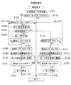
次に、扉2a,2bを開く際の開扉力の特性について説明する。
図32は、閉鎖された扉を開く際の、扉の開角度と開扉力との関係を示すグラフである。
図32に示すように、グラフの横軸は扉2a,2bの開角度(開き角度)であり、θd=0が扉2a,2bが閉じた状態(閉状態)であり、θdmaxが最大開角度である。このθdmax(最大開角度)は、冷蔵庫1の設置場所に近接した図示しない壁面等に当接した場合の開角度(例えば、90°)を表す。θ1は、開扉装置60の突出部材61a,61bによって扉2a,2bが最大突出量H2(図4参照)押し出されたときの角度である。θ2は、クローザ37(図5(a)参照)が扉2a,2bに閉じ力(閉状態とする閉じ方向の回転トルク)を生じさせる角度ψ1(図6(b)参照)である。つまり、開扉装置60によって押し開かれたときの扉2a,2bの開角度は、扉2a,2bに閉じ力を与える上限である角度ψ1よりも小さく設定されている。
Next, the characteristics of the door opening force when opening the doors 2a and 2b will be described.
FIG. 32 is a graph showing the relationship between the opening angle of the door and the opening force when the closed door is opened.
As shown in FIG. 32, the horizontal axis of the graph is the opening angle (opening angle) of the doors 2a and 2b, θd = 0 is the state in which the doors 2a and 2b are closed (closed state), and θdmax is the maximum opening angle. It is. This θdmax (maximum opening angle) represents an opening angle (for example, 90 °) when abutting against a wall surface (not shown) close to the place where the refrigerator 1 is installed. θ1 is an angle when the doors 2a and 2b are pushed out by the protruding members 61a and 61b of the door opening device 60 to the maximum protruding amount H2 (see FIG. 4). θ2 is an angle ψ1 (see FIG. 6B) that causes the closer 37 (see FIG. 5A) to generate a closing force (rotational torque in the closing direction to be in the closed state) on the doors 2a and 2b. That is, the opening angle of the doors 2a and 2b when being pushed open by the door opening device 60 is set to be smaller than the angle ψ1, which is the upper limit for applying a closing force to the doors 2a and 2b.

グラフの縦軸は扉(冷凍室扉)2aと扉(冷蔵室扉)2bの開扉力を示す。この開扉力としては、例えばヒンジ17a,17b(図1参照)まわりのトルクでもよいし、又は扉2a,2bのヒンジ17a,17b(図1参照)から最も離れた扉端部、手掛け部等における引き力でもよい。   The vertical axis of the graph represents the opening force of the door (freezer compartment door) 2a and the door (refrigerator compartment door) 2b. As this door opening force, for example, torque around the hinges 17a and 17b (see FIG. 1) may be used, or the door end portion, the handle portion, etc. that are farthest from the hinges 17a and 17b (see FIG. 1) of the doors 2a and 2b. The pulling force at may be used.

扉2a,2bのドアパッキン15(図1参照)は、図示しないマグネットを内蔵しており、断熱箱体10(図1参照)の前面に吸着して隙間が生じないようにしている。これにより扉2a,2bの開き始めは、クローザ37の負荷に加えてマグネットが吸着した断熱箱体10の前面からドアパッキン15を引き剥がすための開扉力(パッキン負荷)が必要となる。この引き剥しのための開扉力(パッキン負荷)は、扉2a,2bの開き始めは大きく、わずかでも開けばマグネットの吸着力(磁気力)は急激に低下するので開扉力は急激に小さくなる。   The door packing 15 (see FIG. 1) of the doors 2a and 2b incorporates a magnet (not shown), and is attracted to the front surface of the heat insulating box 10 (see FIG. 1) so that no gap is generated. As a result, in order to open the doors 2a and 2b, in addition to the load of the closer 37, a door opening force (packing load) is required for peeling the door packing 15 from the front surface of the heat insulating box 10 to which the magnet is adsorbed. The door opening force (packing load) for peeling off is large when the doors 2a and 2b start to open, and even if they are opened slightly, the magnet's attracting force (magnetic force) decreases rapidly, so the door opening force decreases rapidly. Become.

また、左側の扉2aは、大きな開口を有する冷凍室10gを開閉する扉であるので、扉2aを開閉したときに、外から入った湿気が氷結する(ガスが固体になる)。これにより、冷凍室10g内が負圧になるので、閉じた直後に開扉しようとすると扉2aを開けにくくなる。このように、扉2aを開く際には、負圧を考慮した開扉力(負圧による負荷)が更に加わる。つまり、左側の扉2aは、右側の冷蔵室の扉2bと比べて開き始めにおける開扉力が大となる。   Further, since the left door 2a is a door that opens and closes the freezer compartment 10g having a large opening, when the door 2a is opened and closed, moisture entering from outside freezes (gas becomes solid). Thereby, since the inside of the freezer compartment 10g becomes a negative pressure, it is difficult to open the door 2a when trying to open the door immediately after closing. Thus, when opening the door 2a, the door opening force (load by negative pressure) which considered the negative pressure is further added. That is, the door 2a on the left side has a larger opening force at the beginning of opening than the door 2b of the right refrigerator compartment.

支点摩擦負荷は、主にヒンジ17a,17bの摩擦抵抗により生じる摩擦トルクであるから、開角度の全範囲においてほぼ一様に生じる。
したがって、扉2a,2bの開扉力は、開き始めのθd=0において最大であり、突出部材61a,61bの突き出し範囲(加速範囲)であるθ1までの間に急激に減少し、最大開角度であるθdmaxまではほぼ一様な摩擦トルクが生じる。
Since the fulcrum friction load is a friction torque generated mainly by the frictional resistance of the hinges 17a and 17b, the fulcrum friction load is generated almost uniformly in the entire range of the opening angle.
Therefore, the door opening force of the doors 2a and 2b is maximum at θd = 0 at the beginning of opening, and decreases sharply to θ1 that is the protruding range (acceleration range) of the protruding members 61a and 61b, and the maximum opening angle A substantially uniform friction torque is generated up to θdmax.

次に、開扉装置60によって扉2a,2bを開く際の、好適な開き特性(角速度特性、角度変位特性)について説明する。   Next, suitable opening characteristics (angular velocity characteristics, angular displacement characteristics) when the doors 2a and 2b are opened by the door opening device 60 will be described.

使用者の左開扉スイッチ48a又は右開扉スイッチ48bの操作によって、前記のように、突出部材61a又は突出部材61bが動作すると、扉2a,2bは使用者に向かって開く。このとき扉2a,2bの動きに違和感がなく自然な印象が感じられるように、扉2a,2bを開くことが望ましい。   As described above, when the protruding member 61a or the protruding member 61b is operated by the user's operation of the left opening switch 48a or the right opening switch 48b, the doors 2a and 2b are opened toward the user. At this time, it is desirable to open the doors 2a and 2b so that the movements of the doors 2a and 2b have no sense of incongruity and a natural impression is felt.

扉2a,2bは閉じた状態では言うまでもなく速度=0の停止状態であり、停止状態から開扉動作を行うには、速度が0から加速する加速度運動を行う。扉2a,2bは回転扉なので、その運動は角加速度運動であるが、説明を解かりやすくするために扉2a,2bは単に加速度運動を行うものとする。   Needless to say, the doors 2a and 2b are in a stopped state at a speed = 0, and in order to perform a door opening operation from the stopped state, an acceleration motion in which the speed is accelerated from 0 is performed. Since the doors 2a and 2b are revolving doors, the movement is an angular acceleration movement. However, in order to make the explanation easy to understand, the doors 2a and 2b simply perform an acceleration movement.

使用者に自然な印象を与える開扉動作としては、突出部材61a,61bが突出動作を行っている間においては、扉2a,2bがスムーズな一様な加速を行うものが望ましい。ここで、「一様な加速を行う」とは等加速度運動を意味し、等加速度運動の間は速度が直線的に加速していく。   As the door opening operation that gives a natural impression to the user, it is desirable that the doors 2a and 2b perform smooth and uniform acceleration while the protruding members 61a and 61b perform the protruding operation. Here, “perform uniform acceleration” means a uniform acceleration motion, and the velocity is linearly accelerated during the uniform acceleration motion.

ここで、等加速度運動は自然界にある物体の運動として最も一般的なものなので、自然なものとして感じられる。例えば、自由落下の際の物体の運動は等加速度運動であり、あるいは摩擦のある面を滑りつつ減速する物体の運動は負の方向への等加速度運動である。
このように、物体が一定の力を受けながら加減速する運動は全て等加速度運動なので、日常的に目にしている運動であるためごく自然なものと感じられる。したがって、扉2a,2bは、等加速度運動に近似した開き動作を行うことで、自然な印象を与える開扉動作となる。
Here, since the uniform acceleration motion is the most common motion of an object in the natural world, it can be felt as natural. For example, the motion of the object at the time of free fall is a constant acceleration motion, or the motion of an object that decelerates while sliding on a friction surface is a constant acceleration motion in a negative direction.
In this way, all the motions that accelerate and decelerate while the object receives a certain force are equal acceleration motions, so it is a natural motion because it is a motion that is seen daily. Therefore, the doors 2a and 2b are opened to give a natural impression by performing an opening operation similar to a uniform acceleration motion.

等加速度運動を行う物体の速度は、時間的に一定の割合で増加ないし減少する。したがって、本実施形態の開扉装置60においては、突出部材61a,61bの突出動作を、突出の当初は低速で、徐々に速度を増加させて、突出の終了の間際に最大速度が得られるように設定する。これにより突出部材61a,61bは、等加速度運動に近い扉2a,2bの加速感を得ることができる開扉動作を行い、開扉動作が自然に感じられる開扉装置60を実現する。   The speed of an object that performs a uniform acceleration motion increases or decreases at a constant rate over time. Therefore, in the door opening device 60 of the present embodiment, the projecting operation of the projecting members 61a and 61b is performed at a low speed at the beginning of the projecting, and the speed is gradually increased so that the maximum speed can be obtained just before the projecting ends. Set to. Thereby, the protrusion members 61a and 61b perform the door opening operation | movement which can obtain the acceleration feeling of the doors 2a and 2b close | similar to a uniform acceleration motion, and implement | achieve the door opening apparatus 60 which can feel door opening operation | movement naturally.

突出部材61a,61bの動作は直線運動であり、扉2a,2bは回転運動なので、その運動方向や単位も異なるが、後に詳しく説明するように、突出部材61a,61bの速度と扉2a,2bの角速度との間には比例関係がある。突出部材61a,61bが等加速度運動に近似した挙動を行うことで、扉2a,2bが好適な等角加速度運動に近似した挙動をする。   The movement of the projecting members 61a and 61b is a linear motion, and the doors 2a and 2b are rotational motions. Therefore, the direction and unit of motion are different, but as will be described in detail later, the speed of the projecting members 61a and 61b There is a proportional relationship with the angular velocity. When the protruding members 61a and 61b perform a behavior approximating a uniform acceleration motion, the doors 2a and 2b perform a behavior approximating a suitable uniform angular motion.

図33(a)は、扉を開く際の好ましい扉の角速度と開く時間との関係を示すグラフである。横軸は時間を示し、縦軸は扉2a,2bの角速度を示す。図33(b)は、扉の開角度と開く時間との関係を示すグラフである。横軸は時間を示し、縦軸は扉2a,2bの開角度を示す。なお、図33(a)及び図33(b)において示す実線は、扉2a,2bが開角度90°の位置で停止した場合を示し、破線は、扉2a,2bが開角度90°を超えて開いた場合を示している。   FIG. 33A is a graph showing a relationship between a preferable door angular velocity and opening time when the door is opened. The horizontal axis indicates time, and the vertical axis indicates the angular velocity of the doors 2a and 2b. FIG. 33B is a graph showing the relationship between the opening angle of the door and the opening time. The horizontal axis indicates time, and the vertical axis indicates the opening angle of the doors 2a and 2b. 33 (a) and 33 (b), the solid line indicates the case where the doors 2a and 2b are stopped at the opening angle of 90 °, and the broken line indicates that the doors 2a and 2b exceed the opening angle of 90 °. Shows the case of opening.

図33(a)において実線で示すように、時間t=0では扉2a,2bは閉じられている。t=0からt=1に至るまでの時間遅れののち、t=t1で開扉装置60に通電して開扉装置60を動作させると、t=t1からt2に至るまで、突出部材61a,61bは、扉2a,2b方向に突出する。t=t1からt2に至るまでは、扉2a,2bを加速しつつ開く加速範囲となる。すなわち、図31(a)から図31(b)における扉2aの動作、又は図31(c)から図31(d)における扉2bの動作は、この加速範囲の動作となる。   As shown by a solid line in FIG. 33A, the doors 2a and 2b are closed at time t = 0. After a time delay from t = 0 to t = 1, when the opening device 60 is operated by energizing the door opening device 60 at t = t1, the projecting members 61a, 61b protrudes in the door 2a, 2b direction. From t = t1 to t2, it is an acceleration range that opens while accelerating the doors 2a and 2b. That is, the operation of the door 2a in FIGS. 31 (a) to 31 (b) or the operation of the door 2b in FIGS. 31 (c) to 31 (d) is an operation in this acceleration range.

この加速範囲においては、角速度は時間と共に一様に増加するのでグラフは右上がりの直線となり、t=t2において最大の角速度ωdmaxとなる。
t=t2からt=t3に至るまでの間、扉2a,2bは突出部材61a,61bによる加速は行われない。t=t2からt=t3に至るまでの間は、扉2a,2bが減速しながら開く減速範囲となる。
In this acceleration range, the angular velocity increases uniformly with time, so the graph becomes a straight line rising to the right, and the maximum angular velocity ωdmax at t = t2.
During the period from t = t2 to t = t3, the doors 2a and 2b are not accelerated by the protruding members 61a and 61b. From t = t2 to t = t3, the doors 2a and 2b are in a deceleration range that opens while decelerating.

すなわち、図31(b)から図31(c)における扉2aの動作、又は図31(d)から図31(e)における扉2bの動作は、減速範囲の動作となる。その減速範囲の間、扉2a,2bは、ヒンジ17a,17bから摩擦抵抗(支点摩擦負荷)を受けるので、惰性(慣性力)で開き続けると共に徐々に減速する。また、扉2a,2bは、減速範囲の間、クローザ37による摩擦抵抗(クローザ負荷)を受けるので、惰性(慣性力)で開き続けると共に徐々に減速する。   That is, the operation of the door 2a in FIGS. 31 (b) to 31 (c) or the operation of the door 2b in FIGS. 31 (d) to 31 (e) is an operation in the deceleration range. During the deceleration range, the doors 2a and 2b receive frictional resistance (fulcrum friction load) from the hinges 17a and 17b, so that the doors 2a and 2b continue to open with inertia (inertial force) and gradually decelerate. Further, since the doors 2a and 2b receive frictional resistance (closer load) by the closer 37 during the deceleration range, the doors 2a and 2b continue to open with inertia (inertial force) and gradually decelerate.

摩擦抵抗は、一般的に質量と摩擦係数とを掛けて得られる一定の力であり、本実施形態のように回転ヒンジの場合には、扉2a,2bの質量を支持する部分の直径に応じて摩擦トルクが生じる。
扉2a,2bが惰性で開く間、一定の摩擦トルクによって減速するので、その減速範囲の間の角速度は時間と共に一様に減少し、グラフは右下がりの直線となる。t=t3において扉2a,2bが停止するまでは、t=t2からt=t3までの間は、負の方向への等加速度運動となる。
The frictional resistance is a constant force generally obtained by multiplying the mass and the coefficient of friction. In the case of a rotary hinge as in this embodiment, the frictional resistance depends on the diameter of the portion that supports the mass of the doors 2a and 2b. Friction torque is generated.
While the doors 2a and 2b open by inertia, the vehicle is decelerated by a constant friction torque, so that the angular velocity between the deceleration ranges decreases uniformly with time, and the graph becomes a straight line that goes to the right. Until the doors 2a and 2b stop at t = t3, a constant acceleration motion in the negative direction is performed from t = t2 to t = t3.

図33(b)において実線で示す角度変位のグラフに示すように、時間t=t1からt2に至る加速範囲において、扉2a,2bの開角度θdは、下方に凸となる二次曲線的に増加する。また、時間t2からt3までの減速範囲において、扉2a,2bの開角度θdは、上方に凸となる二次曲線的に増加する。そして、扉2a,2bの開角度θdは、t=t3において最大開角度θdmaxとなる。前記の下方に凸の二次曲線と上方に凸の二次曲線とは連続している。ここで、θdmaxとしては90゜ないしそれ以上の角度に設定すれば、扉2a,2bが食品の出し入れを行うのに十分に開かれるので、使いやすく好適である。   As shown in the graph of angular displacement shown by the solid line in FIG. 33 (b), in the acceleration range from time t = t1 to t2, the opening angle θd of the doors 2a and 2b is a quadratic curve that protrudes downward. To increase. In the deceleration range from time t2 to time t3, the opening angle θd of the doors 2a and 2b increases in a quadratic curve that is convex upward. The opening angle θd of the doors 2a and 2b is the maximum opening angle θdmax at t = t3. The downwardly convex quadratic curve and the upwardly convex quadratic curve are continuous. Here, if θdmax is set to an angle of 90 ° or more, the doors 2a and 2b are sufficiently opened for taking in and out food, which is easy to use and suitable.

一方、図33(a)において破線で示すように、時間t=2からt=t3に至る減速範囲において、t=t3において扉2a,2bの開き動作が止まらず、角速度ωd90(≠0)となった場合、戻り範囲の動作となる。すなわち、戻り範囲の間、第1傾斜面39dが第3傾斜面38eを上ること、また第3傾斜面39fが第1傾斜面38cを上ることで(図6(e)参照)、角速度ωdの傾きが若干変わり、t=t3からt=t4で角速度ωdが0(ゼロ)となる。そして、第1傾斜面39dが第3傾斜面38eを閉じ方向に滑り下り、また第3傾斜面39fが第1傾斜面38cを閉じ方向に滑り下りることで(図6(e)参照)、t=t4からt=t5で角速度ωdがマイナスとなって、t=t5において0(ゼロ)となる。   On the other hand, as shown by the broken line in FIG. 33A, in the deceleration range from time t = 2 to t = t3, the opening operation of the doors 2a and 2b does not stop at t = t3, and the angular velocity ωd90 (≠ 0). When it becomes, it becomes the operation of the return range. That is, during the return range, the first inclined surface 39d goes up the third inclined surface 38e, and the third inclined surface 39f goes up the first inclined surface 38c (see FIG. 6E), the angular velocity ωd The inclination slightly changes, and the angular velocity ωd becomes 0 (zero) from t = t3 to t = t4. Then, the first inclined surface 39d slides down in the closing direction of the third inclined surface 38e, and the third inclined surface 39f slides down in the closing direction of the first inclined surface 38c (see FIG. 6E), t = T4 to t = t5, the angular velocity ωd becomes negative, and becomes 0 (zero) at t = t5.

また、図33(b)において破線で角度変位のグラフに示すように、時間t2からt3までの減速範囲において、扉2a,2bの開動作が開角度θdmax(例えば、90°)で止まらず、一旦開き過ぎたとしても、第3傾斜面38e,39fを設けることで、t=t4で最大の開角度に至った後、閉じ方向に回動してt=t5でθdmaxに戻る。   Also, as shown in the graph of angular displacement with a broken line in FIG. 33B, the opening operation of the doors 2a and 2b does not stop at the opening angle θdmax (for example, 90 °) in the deceleration range from time t2 to t3, Even if the opening is once excessive, by providing the third inclined surfaces 38e and 39f, after reaching the maximum opening angle at t = t4, it rotates in the closing direction and returns to θdmax at t = t5.

次に、開扉装置60によって扉2a,2bを開く際の、好適な開き動作時間について説明する。
一般に、成人の反射時間は0.2秒から0.3秒であると言われており、これは例えば物体が落下し始めたことを認識してから手指でつかむまでの時間、として知られている。
Next, a preferable opening operation time when the doors 2a and 2b are opened by the door opening device 60 will be described.
In general, it is said that the reflex time of an adult is 0.2 to 0.3 seconds, which is known as the time from when an object starts to fall until it is grasped with a finger. Yes.

この反射時間よりも短時間の現象は高速すぎて唐突なものと感じ、違和感を覚えるので、開扉装置60を用いて扉2a、2bを開く際には、左開扉スイッチ48a又は右開扉スイッチ48bを操作してから、扉2a又は扉2bが開き始めて最大の速度ないし最大の角速度ωdmaxに到達するまでの動作時間t2を0.3秒以上に設定すれば、扉2a、2bの開扉動作を唐突と感じることがなく、自然な動作であると感じる。   The phenomenon shorter than the reflection time is too fast and feels abrupt and uncomfortable. Therefore, when opening the doors 2a and 2b using the door opening device 60, the left door switch 48a or the right door is opened. If the operation time t2 from when the switch 48b is operated until the door 2a or the door 2b starts to open until reaching the maximum speed or the maximum angular speed ωdmax is set to 0.3 seconds or more, the doors 2a and 2b are opened. I do not feel the movement suddenly and feel it is natural.

左開扉スイッチ48a及び右開扉スイッチ48bの操作時としては、これらを手指で押した時点であってもよいし、これらから手指を離した時点であってもよい。しかし、これらから手指を離すよりも先に扉2a,2bが開き始めると、手指が開く扉2a,2bに押されて唐突な印象となる。よって、扉2a,2bは、左開扉スイッチ48a又は右開扉スイッチ48bから手指を離した後に開き始めるものが望ましい。   When the left door switch 48a and the right door switch 48b are operated, they may be when they are pressed with fingers, or may be when the fingers are released from them. However, when the doors 2a and 2b begin to open before the fingers are released from these, the fingers are pushed by the doors 2a and 2b that open, giving a sudden impression. Therefore, it is desirable that the doors 2a and 2b start to open after the fingers are released from the left door switch 48a or the right door switch 48b.

前記の時間t2を0.3秒以上とするためには、例えば使用者が左開扉スイッチ48a又は右開扉スイッチ48bを操作した後、0.1秒程度の時間遅れをもってt1となるタイミングで開き始めることが望ましい。そして、t1となった後にモータ82に通電して開き動作を開始し、最大の速度ないし最大の角速度ωdmaxに到達するまでの突出動作時間T=(t2−t1)を0.2秒以上に設定することが望ましい。   In order to set the time t2 to 0.3 seconds or more, for example, after the user operates the left door switch 48a or the right door switch 48b, the time t2 becomes a time t1 with a time delay of about 0.1 seconds. It is desirable to start opening. After t1, the motor 82 is energized to start the opening operation, and the protrusion operation time T = (t2-t1) until reaching the maximum speed or the maximum angular speed ωdmax is set to 0.2 seconds or more. It is desirable to do.

一方、動作時間t2が過大であると、開扉動作が不自然に遅いと感じられるので、動作時間t2は、最大でも人の反射時間よりもやや遅い程度の0.7秒以下となるように設定することが望ましい。このように設定することで、開扉装置60は、その開扉動作が速すぎて唐突にすぎることがなく、かつ遅すぎることもなく、適切な開扉動作を行うことができる。
すなわち、モータ82に通電して突出部材61a,61bが突出動作を開始し、扉2a,2bが開き始めて最大の速度ないし最大の角速度ωdmaxに到達するまでの突出動作時間Tは、0.2秒以上、0.6秒以下とすることが好適である。
On the other hand, if the operation time t2 is excessive, the door opening operation is felt to be unnaturally slow, so that the operation time t2 is 0.7 seconds or less, which is slightly slower than the reflection time of the person at the maximum. It is desirable to set. By setting in this way, the door opening device 60 can perform an appropriate door opening operation without the door opening operation being too fast and too sudden, and without being too late.
That is, when the motor 82 is energized, the projecting members 61a and 61b start projecting, the doors 2a and 2b begin to open, and the projecting operation time T from reaching the maximum speed or the maximum angular speed ωdmax is 0.2 seconds. As mentioned above, it is suitable to set it as 0.6 second or less.

前記したように、自然な扉開動作を実現するには、扉2a,2bの開き特性を等加速度ないし等角加速度運動に近似させることが望ましい。また、扉2a,2bが開き始めて最大速度ないし最大角速度に到達するまでの突出動作時間Tは、0.2秒以上、0.6秒以下に設定することが望ましい。また、開扉装置60は、モータ82に特段の速度制御を行うことなく、例えば一定の定格回転速度でモータ82を回転させることで、突出部材61a,61bに等加速度運動に近似した動作を行わせる構成が望ましい。   As described above, in order to realize a natural door opening operation, it is desirable to approximate the opening characteristics of the doors 2a and 2b to equal acceleration or equal angular acceleration motion. Further, it is desirable that the protrusion operation time T from when the doors 2a, 2b start to open until reaching the maximum speed or the maximum angular speed is set to 0.2 seconds or more and 0.6 seconds or less. Further, the door opening device 60 does not perform special speed control on the motor 82, for example, by rotating the motor 82 at a constant rated rotational speed, thereby causing the protruding members 61 a and 61 b to perform an operation approximating a uniform acceleration motion. It is desirable to have a configuration that allows

<突出部材動作>
次に、回転板73a,73bの回転動作により連結板65a,65bと突出部材61a,61bとが移動して扉2a,2bが開く動作について説明する。なお、以下では、扉2aが開く動作についてのみ説明し、この扉2aと同様に動作する扉2bについての説明は省略する。
<Projection member operation>
Next, an operation in which the connecting plates 65a and 65b and the projecting members 61a and 61b move and the doors 2a and 2b open by the rotating operation of the rotating plates 73a and 73b will be described. In the following, only the operation of opening the door 2a will be described, and the description of the door 2b that operates in the same manner as the door 2a will be omitted.

図34の(a)〜(f)は、開扉装置における回転板と連結板との動作説明図である。なお、図34の(a)〜(f)中、符号ra,rc,rf,rj,rn,rqは、連結板65aに設けられた歯101A〜101Pと、回転板73aに設けられた歯102a〜歯102qとの噛み合いピッチ円半径を表している。   (A)-(f) of FIG. 34 is operation | movement explanatory drawing of the rotation board and connection board in a door opening apparatus. 34 (a) to (f), the symbols ra, rc, rf, rj, rn, and rq denote the teeth 101A to 101P provided on the connecting plate 65a and the teeth 102a provided on the rotating plate 73a. ~ Represents the meshing pitch circle radius with the tooth 102q.

図34(a)に示すように、回転板73aは原点位置にある。前記したように、左開扉スイッチ48a(図2参照)が使用者により操作されて回転板73aが反時計方向に回転を開始する。   As shown in FIG. 34A, the rotating plate 73a is at the origin position. As described above, the left opening switch 48a (see FIG. 2) is operated by the user, and the rotating plate 73a starts to rotate counterclockwise.

図34(b)に示すように、回転板73aの歯102c,102dの間に、連結板65aの歯101Cが噛み合って、連結板65aが矢印方向に移動する。これにより、突出部材61aは、突出動作を行い始める。つまり、扉2aは開き始める。   As shown in FIG. 34 (b), the teeth 101C of the connecting plate 65a mesh between the teeth 102c and 102d of the rotating plate 73a, and the connecting plate 65a moves in the direction of the arrow. Thereby, the protruding member 61a starts to perform a protruding operation. That is, the door 2a starts to open.

図34(c)に示すように、回転板73aが更に回転し、回転板73aの歯102f,102gの間に、連結板65aの歯101Fが噛み合って連結板65aが矢印方向に更に移動する。   As shown in FIG. 34C, the rotating plate 73a further rotates, and the teeth 101F of the connecting plate 65a mesh between the teeth 102f and 102g of the rotating plate 73a, so that the connecting plate 65a further moves in the direction of the arrow.

図34(d)に示すように、回転板73aが更に回転し、回転板73aの歯102j,102kの間に、連結板65aの歯101Jが噛み合って連結板65aが矢印方向に更に移動する。   As shown in FIG. 34 (d), the rotating plate 73a further rotates, and the teeth 101J of the connecting plate 65a mesh between the teeth 102j and 102k of the rotating plate 73a, and the connecting plate 65a further moves in the direction of the arrow.

図34(e)に示すように、回転板73aが更に回転し、回転板73aの歯102n,102pの間に、連結板65aの歯101Nが噛み合って連結板65aが矢印方向に更に移動する。   As shown in FIG. 34 (e), the rotating plate 73a further rotates, the teeth 101N of the connecting plate 65a mesh between the teeth 102n and 102p of the rotating plate 73a, and the connecting plate 65a further moves in the direction of the arrow.

図34(f)に示すように、回転板73aが更に回転し、回転板73aの最も外周にある歯102qが連結板65aの後端にある歯101Pを前方に向けて押圧する。連結板65aは矢印方向に更に移動して最大突出量H2となるように突出部材61aを突出させる。突出部材61aの突き出し速度は最大速度となり、その直後に停止する。
そして、回転板73aは、前記したように、逆転方向に(時計回りに)回転して、図34(f)から図34(b)の状態を経て図34(a)に示した原点位置に復帰する。
As shown in FIG. 34 (f), the rotating plate 73a further rotates, and the teeth 102q at the outermost periphery of the rotating plate 73a press the teeth 101P at the rear end of the connecting plate 65a forward. The connecting plate 65a further moves in the direction of the arrow to project the projecting member 61a so that the maximum projecting amount H2 is obtained. The protruding speed of the protruding member 61a is the maximum speed, and stops immediately thereafter.
Then, as described above, the rotating plate 73a rotates in the reverse direction (clockwise), and reaches the origin position shown in FIG. 34 (a) through the state of FIG. 34 (f) to FIG. 34 (b). Return.

次に、連結板65aと突出部材61aと扉2a,2bの速度特性について説明する。
前記したように、連結板65aと回転板73aのそれぞれに設けられた歯101A〜101P、及び歯102a〜102qは、半径がraと最も小さい歯101Aと歯102aから噛み合いが始まる。最終的に半径が最大のrqに至るまで、半径が徐々に増加しつつ噛み合っていく。この際、回転板73aの回転動作は、連結板65aと突出部材61aの直線動作に変換される。
Next, the speed characteristics of the connecting plate 65a, the protruding member 61a, and the doors 2a and 2b will be described.
As described above, the teeth 101A to 101P and the teeth 102a to 102q provided on each of the connecting plate 65a and the rotating plate 73a start to mesh with the teeth 101A and the teeth 102a having the smallest radius ra. Until the radius finally reaches the maximum rq, the radius gradually increases and meshes. At this time, the rotating operation of the rotating plate 73a is converted into a linear operation of the connecting plate 65a and the protruding member 61a.

モータ82が一定速度の定格回転速度で回転し、減速歯車列83によって減速された適切な回転速度で回転板73aが回転した場合には、連結板65aと突出部材61aの移動速度は、動き始めは低速となる。その後、連結板65aと突出部材61aの移動速度は、徐々に加速して最後に最大速度になるような加速特性をもつ。この加速の程度は、回転板73aの最大半径rqと最小半径raとの比、すなわちrq/raで表される。   When the motor 82 rotates at a constant rated rotational speed and the rotating plate 73a rotates at an appropriate rotational speed reduced by the reduction gear train 83, the moving speed of the connecting plate 65a and the protruding member 61a starts to move. Is slow. After that, the moving speed of the connecting plate 65a and the protruding member 61a has an acceleration characteristic that gradually accelerates and finally reaches the maximum speed. The degree of this acceleration is represented by the ratio between the maximum radius rq and the minimum radius ra of the rotating plate 73a, that is, rq / ra.

次に、突出部材61aの突出速度特性及び突出力特性について説明する。
図35(a)は、突出部材が突出する際の、速度と時間との関係を示すグラフである。横軸は時間であり、縦軸は突出部材の突出速度である。図35(b)は、突出部材が突出する際の、力と時間との関係を示すグラフである。横軸は時間であり、縦軸は突出部材の突出力である。なお、図35(a)及び(b)中、t=0は図34(a)の状態を示し、突出部材61aが動作し始めた時点である。Tは、突出部材61aが最大の速度ないし最大の角速度ωdmaxに到達するまでの時間[T=(t2−t1)]である(但し、t1は図34(a)の状態になるまでの時間であり、t2は図34(f)となるまでの時間である)。
Next, the protruding speed characteristic and the protruding output characteristic of the protruding member 61a will be described.
FIG. 35A is a graph showing the relationship between speed and time when the protruding member protrudes. The horizontal axis is time, and the vertical axis is the protruding speed of the protruding member. FIG. 35B is a graph showing the relationship between force and time when the protruding member protrudes. The horizontal axis is time, and the vertical axis is the projecting output of the projecting member. In FIGS. 35A and 35B, t = 0 indicates the state of FIG. 34A, which is the time when the protruding member 61a starts to operate. T is a time [T = (t2−t1)] until the protruding member 61a reaches the maximum velocity or the maximum angular velocity ωdmax (where t1 is the time until the state shown in FIG. 34A). Yes, t2 is the time until it becomes FIG. 34 (f)).

回転板73aの回転速度をN(rpm)とすると、回転板の角速度ω(rad/s)はω=(N/60)×2π ・・・・(式1)
で表される。
この時の突出部材61aの速度は、連結板65aの歯101A〜101Pに噛み合う回転板73aの歯102a〜102qのピッチ円半径の接線方向速度となる。
したがって、図35(a)に示すt1(図34(a)の状態になるまでの時間)における突出部材61aの速度Vaは、ピッチ円半径raの部分の接線方向速度となるので、Va=ω×ra=(N/60)×2π×ra ・・・・(式2)
となる。このVaはごく低速であり、速度0の停止状態から加速される。
When the rotational speed of the rotating plate 73a is N (rpm), the angular velocity ω (rad / s) of the rotating plate is ω = (N / 60) × 2π (Equation 1)
It is represented by
The speed of the protruding member 61a at this time is a tangential speed of the pitch circle radius of the teeth 102a to 102q of the rotating plate 73a meshing with the teeth 101A to 101P of the connecting plate 65a.
Therefore, the speed Va of the protruding member 61a at t1 shown in FIG. 35A (time until the state shown in FIG. 34A) is the tangential speed of the pitch circle radius ra, so Va = ω × ra = (N / 60) × 2π × ra (Expression 2)
It becomes. This Va is very low speed, and is accelerated from the stop state at zero speed.

また、図35(a)に示すt2(図34(f)の状態になるまでの時間)における突出部材61aの速度Vqは、ピッチ円半径rqの部分の接線方向速度となるので、
Vq=ω×rq=(N/60)×2π×rq ・・・・(式3)
となる。
Further, the speed Vq of the protruding member 61a at t2 shown in FIG. 35 (a) (time until the state shown in FIG. 34 (f)) is the tangential speed of the portion of the pitch circle radius rq.
Vq = ω × rq = (N / 60) × 2π × rq (Equation 3)
It becomes.

式2と式3とから明らかなように、突出部材61aの突出速度は、回転板73aと連結板65aとの間で噛み合う歯のピッチ円半径に比例する。
また、前記のように、ピッチ円半径raからrqは、ra<rb<rc<rd<re<rf<rg<rh<rj<rk<rm<rn<rp<rqの関係があるので、例えばrb/raの比、rc/rbの比のように、隣接した歯のピッチ円半径が概ね一様に増加するようにすれば、回転板73aの角速度に比例して突出部材61aの突出速度は増加する。
As is apparent from Equations 2 and 3, the protruding speed of the protruding member 61a is proportional to the pitch circle radius of the teeth meshing between the rotating plate 73a and the connecting plate 65a.
Further, as described above, since the pitch circle radii ra to rq have a relationship of ra <rb <rc <rd <re <rf <rg <rh <rj <rk <rm <rn <rp <rq, for example, rb If the pitch circle radius of adjacent teeth increases substantially uniformly like the ratio of / ra and the ratio of rc / rb, the protruding speed of the protruding member 61a increases in proportion to the angular speed of the rotating plate 73a. To do.

したがって、この開扉装置60によれば、モータ82に特段の速度制御を行うことなく、例えば一定の定格回転速度でモータ82を回転させることで、突出部材61a,61bに等加速度運動に近似した動作を行わせることができる。
そして、この開扉装置60においては、前記したようにt=t2となると、モータ82停止により回転板73aが一旦停止し、その後、モータ82が逆回転することにより突出部材61aが原点に復帰する。
Therefore, according to this door opening device 60, the motor 82 is rotated at a constant rated rotational speed, for example, without performing special speed control on the motor 82, thereby approximating the projecting members 61a and 61b to a uniform acceleration motion. The action can be performed.
In the door opening device 60, when t = t2 as described above, the rotating plate 73a is temporarily stopped by stopping the motor 82, and then the protruding member 61a is returned to the origin by the reverse rotation of the motor 82. .

また、突出部材61aの突出力は、回転板73aと連結板65aとの間で噛み合う歯のピッチ円半径に反比例する。
つまり、突出部材61aの突出力は、図35(b)に示すように、t=t1における突出し力Paが最大値となる。また、突出部材61aの突出力は、連結板65aと噛み合う回転板73aのピッチ円半径がraからrqに増加するに伴って減少する。そして、突出部材61aの突出力は、t=t2において最小値Pqとなるような、一様な減少傾向をもつ。
The projecting output of the projecting member 61a is inversely proportional to the pitch circle radius of the teeth meshing between the rotating plate 73a and the connecting plate 65a.
That is, as shown in FIG. 35B, the projecting force Pa of the projecting member 61a has the maximum projecting force Pa at t = t1. Further, the projecting output of the projecting member 61a decreases as the pitch circle radius of the rotating plate 73a meshing with the connecting plate 65a increases from ra to rq. The projecting output of the projecting member 61a has a uniform decreasing tendency so as to become the minimum value Pq at t = t2.

ところで、本実施形態では、扉2aが開扉装置60によってθdmax(例えば、10°)の開角度で押し開かれたときには、第1傾斜面39dが頂点38sの手前に位置している(図6(a))。このため、ここで設定される速度Vq及び突出力Paは、第1傾斜面39dが頂点38sを乗り越えることができ、しかも第2傾斜面39eが第2傾斜面38d上を滑り下りる際に生じる摩擦力を受けながら、90°開いた状態で扉2aが停止する速度及び突出力となるように設定されることが好ましい。このように設定することで、半ドアを防止するための閉じ力(閉状態となる閉じ方向の回転トルク)を発生させる角度範囲を広く確保することができる。
なお、以上の説明においては、左側の突出部材61aの動作について説明したが、右側の突出部材61bについても左右対称となる以外は左側の突出部材61aと同様に動作する。
By the way, in this embodiment, when the door 2a is pushed open by the opening device 60 at an opening angle of θdmax (for example, 10 °), the first inclined surface 39d is positioned in front of the apex 38s (FIG. 6). (A)). For this reason, the speed Vq and the thrust output Pa set here are the friction generated when the first inclined surface 39d can get over the apex 38s and the second inclined surface 39e slides down on the second inclined surface 38d. It is preferable that the speed is set so that the door 2a stops at a state where the door 2a is opened while the force is received, and the output is a sudden output. By setting in this way, it is possible to secure a wide angle range for generating a closing force (rotational torque in the closing direction to be in a closed state) for preventing the half door.
In the above description, the operation of the left protruding member 61a has been described. However, the right protruding member 61b operates in the same manner as the left protruding member 61a except that the left protruding member 61b is symmetrical.

次に、開扉動作の際の突出部材61a,61bの突出速度と、扉2a,2bのヒンジ17a,17bから最も離れた扉端部における速度との関係について説明する。
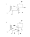
図36(a)は、左側の突出部材を突き出す際の、突出部材の速度と冷凍室扉の端部の速度との関係を示す説明図であり、図36(b)は、右側の突出部材を突き出す際の、突出部材の速度と冷蔵室扉の端部の速度との関係を示す説明図である。
Next, the relationship between the projecting speed of the projecting members 61a and 61b during the opening operation and the speed at the end of the door farthest from the hinges 17a and 17b of the doors 2a and 2b will be described.
FIG. 36A is an explanatory view showing the relationship between the speed of the protruding member and the speed of the end of the freezer compartment door when the left protruding member is protruded, and FIG. 36B is the right protruding member. It is explanatory drawing which shows the relationship between the speed of the protrusion member at the time of protruding, and the speed of the edge part of a refrigerator compartment door.

図36(a)に示すように、突出部材61aの突出速度をV(mm/sec)、ヒンジ17aから突出部材61aまでの距離をRda(mm)、ヒンジ17aから最も離れた扉端部までの距離をLda(mm)、ヒンジ17aから最も離れた扉端部での接線方向速度をWa(mm/sec)、扉2aの角速度をωda(rad/sec)、とすると、次式(4)が成立する。
ωda=V/(2×π×Rda)=Wa/(2×π×Lda) ・・・・(式4)
As shown in FIG. 36 (a), the protruding speed of the protruding member 61a is V (mm / sec), the distance from the hinge 17a to the protruding member 61a is Rda (mm), and the door end that is farthest from the hinge 17a When the distance is Lda (mm), the tangential speed at the end of the door farthest from the hinge 17a is Wa (mm / sec), and the angular velocity of the door 2a is ωda (rad / sec), the following equation (4) is obtained. To establish.
ωda = V / (2 × π × Rda) = Wa / (2 × π × Lda) (Equation 4)

ヒンジ17aから最も離れた扉端部での接線方向速度Waと、突出部材61aの突出速度Vとの関係は、
Wa=(Lda/Rda)×V ・・・・(式5)
となる。
つまり、接線方向速度Waは、ヒンジ17aを基準位置とした際の扉2aの幅と突出部材61aの取付位置との比(Lda/Rda)に比例する。
したがって、突出部材61aが等加速度運動に近似した運動を行えば、扉2aの扉端部も等加速度運動に近似した運動を行うので、自然な開き方を得ることができる。
The relationship between the tangential speed Wa at the door end furthest from the hinge 17a and the protruding speed V of the protruding member 61a is:
Wa = (Lda / Rda) × V (Equation 5)
It becomes.
That is, the tangential speed Wa is proportional to the ratio (Lda / Rda) between the width of the door 2a and the mounting position of the protruding member 61a when the hinge 17a is used as the reference position.
Therefore, if the protruding member 61a performs a motion approximating the uniform acceleration motion, the door end portion of the door 2a also performs a motion approximating the uniform acceleration motion, so that a natural opening can be obtained.

接線方向速度Waの最大値Waqは、突出速度Vが最大値をとるV=Vqの場合であり、次式(6)
Waq=(Lda/Rda)×Vq ・・・・(式6)
で表される。
The maximum value Waq of the tangential speed Wa is a case where V = Vq where the protrusion speed V takes the maximum value.
Waq = (Lda / Rda) × Vq (Expression 6)
It is represented by

次に、扉2bの開扉動作の際の突出部材61aの突出速度と、扉2bのヒンジ17bから最も離れた扉端部における速度との関係について説明する。
図36(b)に示すように、突出部材61bの突出速度をV(mm/sec)、ヒンジ17bから突出部材61bまでの距離をRdb(mm)、ヒンジ17bから最も離れた扉端部までの距離をLdb(mm)、ヒンジ17bから最も離れた扉端部での接線方向速度をWb(mm/sec)、冷蔵室扉2bの角速度をωdb(rad/sec)、とすると、次式(7)が成立する。
ωdb=V/(2×π×Rdb)=Wb/(2×π×Ldb) ・・・・(式7)
Next, the relationship between the protruding speed of the protruding member 61a during the opening operation of the door 2b and the speed at the door end portion farthest from the hinge 17b of the door 2b will be described.
As shown in FIG. 36 (b), the protruding speed of the protruding member 61b is V (mm / sec), the distance from the hinge 17b to the protruding member 61b is Rdb (mm), and the distance from the hinge 17b to the door end that is furthest away is shown. Assuming that the distance is Ldb (mm), the tangential speed at the end of the door farthest from the hinge 17b is Wb (mm / sec), and the angular speed of the refrigerator compartment door 2b is ωdb (rad / sec), ) Holds.
ωdb = V / (2 × π × Rdb) = Wb / (2 × π × Ldb) (Expression 7)

ヒンジ17bから最も離れた扉端部での接線方向速度Wbと突出部材61bの突出速度Vとの関係は、
Wb=(Ldb/Rdb)×V ・・・・(式8)
となる。
つまり、接線方向速度Wbは、ヒンジ17bを基準位置とした際の扉2bの幅と突出部材61bの取付位置との比(Ldb/Rdb)に比例する。
したがって、突出部材61bが等加速度運動に近似した運動を行えば、扉2bの扉端部も等加速度運動に近似した運動を行うので、扉2bは自然な開き方を行うことができる。
The relationship between the tangential speed Wb at the door end farthest from the hinge 17b and the protruding speed V of the protruding member 61b is:
Wb = (Ldb / Rdb) × V (Equation 8)
It becomes.
That is, the tangential speed Wb is proportional to the ratio (Ldb / Rdb) between the width of the door 2b and the mounting position of the protruding member 61b when the hinge 17b is used as the reference position.
Therefore, if the protruding member 61b performs a motion approximating the uniform acceleration motion, the door end portion of the door 2b also performs a motion approximating the uniform acceleration motion, so that the door 2b can be naturally opened.

接線方向速度Wbの最大値Wbqは、突出し速度Vが最大値をとるV=Vqの場合であり、次式(9)
Wbq=(Ldb/Rdb)×Vq ・・・・(式9)
で表される。
The maximum value Wbq of the tangential speed Wb is the case where V = Vq where the protruding speed V takes the maximum value.
Wbq = (Ldb / Rdb) × Vq (Equation 9)
It is represented by

本実施形態の開扉装置60によれば、モータ82を正転方向に一定回転速度で回転すれば、突出部材61aは等加速度運動に近似した運動を行う。一方、モータ82を逆転方向に一定回転速度で回転すれば、突出部材61bは等加速度運動に近似した運動を行う。
したがって、開扉装置60は、特段の速度制御を行うことなく、モータ82を正転又は逆転方向に一定速度で回転すれば自然な開扉動作を行うことができる。
よって、この開扉装置60によれば、制御回路を簡素化することができる。また、開扉装置60によれば、安価な構成で開扉動作に自然な印象を与えることができる。
According to the door opening device 60 of the present embodiment, when the motor 82 is rotated in the normal rotation direction at a constant rotational speed, the protruding member 61a performs a motion that approximates a uniform acceleration motion. On the other hand, when the motor 82 is rotated in the reverse rotation direction at a constant rotational speed, the protruding member 61b performs a motion that approximates a uniform acceleration motion.
Therefore, the door opening device 60 can perform a natural door opening operation by rotating the motor 82 at a constant speed in the normal rotation or reverse rotation direction without performing special speed control.
Therefore, according to the door opening device 60, the control circuit can be simplified. Moreover, according to the door opening device 60, a natural impression can be given to the door opening operation with an inexpensive configuration.

次に、開扉装置60と扉2aと扉2bの好適な配置について説明する。
再び図8に戻って、開扉装置60は、1つのモータ82の正転方向又は逆転方向に回転する際の駆動力を、大歯車76と間欠駆動歯車78a,78bとに伝達して扉2a,2bに対応した突出部材61a、61bの突出動作を行う。
Next, a preferable arrangement of the door opening device 60, the door 2a, and the door 2b will be described.
Returning to FIG. 8 again, the door opening device 60 transmits the driving force when the motor 82 rotates in the forward rotation direction or the reverse rotation direction to the large gear 76 and the intermittent drive gears 78a and 78b, thereby opening the door 2a. , 2b corresponding to the protruding members 61a and 61b.

突出部材61aの突出動作と突出部材61bの突出動作とは、駆動力、速度共に、摩擦抵抗やモータ82の正転方向と逆転方向の特性の相違等の誤差を除けば同一となる。すなわち、突出部材61aの突出速度と突出部材61bの突出速度は略等しく、その最大値は共に図35(a)に示すVq(mm/sec)とすることができる。   The projecting operation of the projecting member 61a and the projecting operation of the projecting member 61b are the same in terms of driving force and speed, except for errors such as frictional resistance and differences in the characteristics of the motor 82 in the forward and reverse directions. That is, the projecting speed of the projecting member 61a and the projecting speed of the projecting member 61b are substantially equal, and the maximum values thereof can be both Vq (mm / sec) shown in FIG.

開扉装置60に設けられた突出部材61a,61bは、それぞれ扉2aと扉2bとに対向した位置にあって、扉2aと扉2bの両方を順次に開くことができる。
突出部材61a、61bは、開扉装置60のケース62の左側面と右側面に近接して配置されており、その間隔は図36に示すGであり、一定の値となる。このGの値は、例えば、150mmから180mm程度に設定することができる。
The projecting members 61a and 61b provided in the door opening device 60 are at positions facing the doors 2a and 2b, respectively, and can sequentially open both the doors 2a and 2b.
The protruding members 61a and 61b are disposed close to the left side surface and the right side surface of the case 62 of the door opening device 60, and the distance between them is G shown in FIG. 36, which is a constant value. The value of G can be set to about 150 mm to 180 mm, for example.

また、図示しないが、扉2aの幅Lda(図36(a)参照)と扉2bの幅Ldb(図36(b)参照)とが等しく(Lda=Ldb)、扉2a及び扉2bが左右対称である場合には、開扉装置60の左右中心を、扉2a,2bの扉境界72a,72b(図36(a)及び(b)参照)の中心と合致させて左右対称の位置に配置する。これにより、扉2aにおける突出部材61aとヒンジ17aの距離Rda(図36(a)参照)と、扉2bにおける突出部材61bとヒンジ17bの距離Rdb(図36(b)参照)とは、Rda=Rdbとなる。このような開扉装置60の配置は、扉2aと扉2bの開き方に相違が生じないので望ましい。   Although not shown, the width Lda of the door 2a (see FIG. 36A) and the width Ldb of the door 2b (see FIG. 36B) are equal (Lda = Ldb), and the door 2a and the door 2b are symmetrical. In this case, the left and right centers of the door opening device 60 are aligned with the centers of the door boundaries 72a and 72b (see FIGS. 36 (a) and (b)) of the doors 2a and 2b and are arranged at symmetrical positions. . Accordingly, the distance Rda (see FIG. 36A) between the protruding member 61a and the hinge 17a in the door 2a and the distance Rdb (see FIG. 36B) between the protruding member 61b and the hinge 17b in the door 2b are Rda = Rdb. Such an arrangement of the door opening device 60 is desirable because there is no difference in how the doors 2a and 2b are opened.

次に、扉2aと扉2bの幅が異なる場合の開扉装置60の好適な配置について説明する。
開扉装置60により扉2a,扉2bの開扉動作を行う際、使用者は冷蔵庫1の正面に立ち、扉2a,2bの扉境界72a,72b(図36(a)及び(b)参照)の前辺りから手を伸ばして左開扉スイッチ48a又は右開扉スイッチ48bを操作する。
Next, the suitable arrangement | positioning of the door opening apparatus 60 when the width | variety of the door 2a and the door 2b differs is demonstrated.
When performing the door opening operation of the doors 2a and 2b by the door opening device 60, the user stands in front of the refrigerator 1 and the door boundaries 72a and 72b of the doors 2a and 2b (see FIGS. 36A and 36B). The left door switch 48a or the right door switch 48b is operated by reaching out from the front.

使用者から見ると、開扉装置60が動作して扉2aが開く際には、扉2aのヒンジ17aから最も離れた扉端部が接線速度Waで自分に向って接近する動作となる。また、扉2bが開く際には、扉2bのヒンジ17bから最も離れた扉端部が接線速度Wbで自分に向かって接近する動作となる。   When viewed from the user, when the door opening device 60 operates to open the door 2a, the door end that is farthest from the hinge 17a of the door 2a approaches the user at a tangential speed Wa. Further, when the door 2b is opened, the door end that is farthest from the hinge 17b of the door 2b moves toward itself at the tangential speed Wb.

したがって、扉2a,2bの開扉動作に際しては、扉2a,2bの最大接線速度Waq,Wbq(図36(a)及び(b)参照)が略等しければ、使用者は扉2a,2bの開き速度を略等しいと感じる。したがって、扉2a,2bの幅が異なる場合にも、最大接線速度Waq=Wbqとなるような位置に開扉装置60を設けることが望ましい。そのような条件を満たす開扉装置60の配置位置について、次に説明する。   Therefore, when the doors 2a and 2b are opened, if the maximum tangential speeds Waq and Wbq (see FIGS. 36A and 36B) of the doors 2a and 2b are substantially equal, the user opens the doors 2a and 2b. I feel the speed is almost equal. Therefore, even when the widths of the doors 2a and 2b are different, it is desirable to provide the door opening device 60 at a position where the maximum tangential velocity Waq = Wbq. Next, the arrangement position of the opening device 60 that satisfies such conditions will be described.

図36(a)及び図36(b)に示すように、突出部材61aと突出部材61bとの距離をG、扉境界72aから突出部材61aまでの距離をGa、扉境界72bから突出部材61bまでの距離をGb、とすると、扉境界72a,72b間の距離は、扉2a,2bの幅と比べて十分に小さいものとしてこれを無視することができる。つまり、次式(10)が成立する。
G=Ga+Gb ・・・・(式10)
As shown in FIGS. 36A and 36B, the distance between the protruding member 61a and the protruding member 61b is G, the distance from the door boundary 72a to the protruding member 61a is Ga, and the door boundary 72b to the protruding member 61b. If the distance of Gb is Gb, the distance between the door boundaries 72a and 72b can be ignored as it is sufficiently smaller than the width of the doors 2a and 2b. That is, the following expression (10) is established.
G = Ga + Gb (Equation 10)

また、図36(a)及び(b)に示すように、次式(11)及び次式(12)が成立することが明らかである。
Rda=Lda−Ga ・・・・(式11)
Rdb=Ldb−Gb ・・・・(式12)
Further, as shown in FIGS. 36A and 36B, it is clear that the following expressions (11) and (12) are established.
Rda = Lda-Ga (formula 11)
Rdb = Ldb−Gb (Equation 12)

また、前記式6より
Waq=(Lda/Rda)×Vq={Lda/(Lda−Ga)}×Vq ・・・・(式13)
が導かれ、(式9)より
Wbq=(Ldb/Rdb)×Vq={Ldb/(Ldb−Gb)}×Vq ・・・・(式14)
が導かれる。
Further, from Equation 6, Waq = (Lda / Rda) × Vq = {Lda / (Lda−Ga)} × Vq (Equation 13)
From (Expression 9), Wbq = (Ldb / Rdb) × Vq = {Ldb / (Ldb−Gb)} × Vq (Expression 14)
Is guided.

そして、前記式13と前記式14とが等しくなる条件は、両式の右辺を等しいとおいて、
{Lda/(Lda−Ga)}=(Ldb/(Ldb−Gb)} ・・・・(式15)
となり、式を展開して更に(式10)を代入すると
Lda×{Ldb−(G−Ga)}=Ldb×(Lda−Ga)
Lda×(G−Ga)=Ldb×Ga
Lda×G=(Lda+Ldb)×Ga
ゆえに、Ga=G×{Lda/(Lda+Ldb)} ・・・・(式16)
となる。
And, the condition that the expression 13 and the expression 14 are equal is that the right sides of both expressions are equal,
{Lda / (Lda-Ga)} = (Ldb / (Ldb-Gb)} (Equation 15)
Then, by expanding the equation and substituting (Equation 10), Lda × {Ldb− (G−Ga)} = Ldb × (Lda−Ga)
Lda × (G−Ga) = Ldb × Ga
Lda × G = (Lda + Ldb) × Ga
Therefore, Ga = G × {Lda / (Lda + Ldb)} (Equation 16)
It becomes.

式16の左辺のGaは、扉2aを開放する突出部材61aの扉境界72aからの距離である。したがって、このGaを、開扉装置60を冷蔵庫1に取り付ける際の代表寸法とすれば、前記式16の右辺は、開扉装置60の構成によって定まる突出部材61aと突出部材61bとの間の距離Gと、扉2aのヒンジ17aからの幅Ldaと、扉2bのヒンジ17bからの幅Ldbと、によって定まる定数となる。   Ga on the left side of Equation 16 is the distance from the door boundary 72a of the protruding member 61a that opens the door 2a. Therefore, if this Ga is a representative dimension when the opening device 60 is attached to the refrigerator 1, the right side of the equation 16 is the distance between the protruding member 61a and the protruding member 61b determined by the configuration of the opening device 60. It is a constant determined by G, the width Lda from the hinge 17a of the door 2a, and the width Ldb from the hinge 17b of the door 2b.

すなわち、前記式16によって求められるGaの位置に突出部材61aが配置されるように開扉装置60を冷蔵庫1に設けることによって、突出部材61a,61bの突出速度が等しい場合に扉2a,2bの最大接線速度Waq,Wbqが等しくなる。これにより、使用者は扉2a,2bの開速度が概ね等しいと感じることができる。したがって、この開扉装置60によれば、扉2a,2bの幅が異なる場合であっても開扉動作のバランスが良く、自然な開扉動作を実現できる。   In other words, by providing the refrigerator 1 with the door opening device 60 so that the protruding member 61a is arranged at the Ga position obtained by the above equation 16, when the protruding speeds of the protruding members 61a and 61b are equal, The maximum tangential velocities Waq and Wbq are equal. Thereby, the user can feel that the opening speeds of the doors 2a and 2b are substantially equal. Therefore, according to this door opening device 60, even when the doors 2a and 2b have different widths, the door opening operation is well balanced and a natural door opening operation can be realized.

ここで、扉2a,2bの幅Lda,Ldb(図36(a)及(b)参照)が最大約500mmから最小約280mmまでの各種冷蔵庫1を用いて扉2a,2bの開速度を評価した。その結果、前記の最大接線速度Waq,Wbqを概ね700から1100mm/secとなるように設定すれば、使用者は扉2a,2bの開速度が速すぎることも遅すぎることもない適切な開扉動作として感じられる、ということが判明した。   Here, the opening speeds of the doors 2a and 2b were evaluated using various refrigerators 1 with the widths Lda and Ldb (see FIGS. 36A and 36B) of the doors 2a and 2b ranging from a maximum of about 500 mm to a minimum of about 280 mm. . As a result, if the maximum tangential velocities Waq and Wbq are set to be approximately 700 to 1100 mm / sec, the user can open the doors 2a and 2b at an appropriate opening speed that is neither too fast nor too slow. It turns out that it feels as a movement.

ところで、図36(a)に示した扉2aは、冷凍室10gを開閉する冷凍室扉である。したがって、扉2aを開く際には、負圧による負荷(図32参照)が加算されるので、開扉力が扉(冷蔵室扉)2bを開く場合よりも大である。したがって、扉2bを開く場合と比較して扉2aは開きにくい。そこで、開扉装置60の取り付け位置としては、前記Ga(式16参照)よりも、開扉装置60を扉2bの側に移動すること、言い換えれば図36(a)に示すRda寸法を大とすることが望ましい。これにより扉2aを開く際のヒンジ17aまわりのモーメントを大として、扉2aを開きやすくすることができる。   By the way, the door 2a shown to Fig.36 (a) is a freezer compartment door which opens and closes the freezer compartment 10g. Therefore, when the door 2a is opened, a load due to negative pressure (see FIG. 32) is added, so the door opening force is larger than when the door (refrigeration room door) 2b is opened. Therefore, the door 2a is hard to open compared with the case where the door 2b is opened. Therefore, as the mounting position of the door opening device 60, the door opening device 60 is moved to the door 2b side, in other words, the Rda dimension shown in FIG. It is desirable to do. As a result, the moment around the hinge 17a when the door 2a is opened can be increased, and the door 2a can be easily opened.

次に、突出部材61aによる突出力の特性について説明する。
前記したように、扉2a,2bの開き力特性(図32参照)は、扉2a,2bの開き始めはマグネットが吸着したドアパッキン15を引きはがすための開き力が必要なので開き力は大きい。しかし、わずかでも扉2a,2bが開けばマグネットの磁気吸着力は急激に低下するので、開き力は急激に小さくなる。
Next, the characteristics of the projecting output by the projecting member 61a will be described.
As described above, the opening force characteristics of the doors 2a and 2b (see FIG. 32) are large because the opening force for tearing off the door packing 15 attracted by the magnet is required at the beginning of the opening of the doors 2a and 2b. However, even if the doors 2a and 2b are opened even slightly, the magnetic attractive force of the magnet decreases rapidly, so the opening force decreases rapidly.

したがって、突出部材61aの好適な突出力の特性としては、開動作の開始時の突出力が最大となるような特性が望ましい。
図34(a)〜(f)に示したように、連結板65aと回転板73aの歯の噛み合いは、最も小さいピッチ半径raで始まり、最も大きいピッチ半径rqにまで至る。その間、ピッチ半径が徐々に増加しながら、回転板73aの回転動作は、連結板65a及び突出部材61aの直線動作に変換される。
Therefore, it is desirable that the characteristic of the projecting force of the projecting member 61a is such that the projecting power at the start of the opening operation is maximized.
As shown in FIGS. 34A to 34F, the meshing of the teeth of the connecting plate 65a and the rotating plate 73a starts with the smallest pitch radius ra and reaches the largest pitch radius rq. Meanwhile, while the pitch radius gradually increases, the rotation operation of the rotating plate 73a is converted into a linear operation of the connecting plate 65a and the protruding member 61a.

このような構成の開扉装置60によれば、前記のように、連結板65aから突出部材61aに伝達される突出力は、動き始めは大きく、徐々に低減して最後に最小となる。この突出力の低減程度は、前記のように、回転板73aの最小半径raと最大半径rqとの比(ra/rq)で表される。   According to the door opening device 60 having such a configuration, as described above, the projecting output transmitted from the connecting plate 65a to the projecting member 61a is large at the beginning of movement, gradually decreased, and finally minimized. As described above, the reduction degree of the projecting output is represented by the ratio (ra / rq) between the minimum radius ra and the maximum radius rq of the rotating plate 73a.

また、このような構成の開扉装置60によれば、前記のように、突出動作時間Tを0.2秒以上0.6秒以下に設定することで、開動作を唐突と感じることがなく、かつ遅すぎることもなく、自然な動作であると感じる。   Further, according to the door opening device 60 having such a configuration, as described above, the opening operation time T is set to 0.2 seconds or more and 0.6 seconds or less, so that the opening operation does not feel suddenly. And it feels natural movement without being too slow.

また、開扉装置60においては、前記したように、突出部材61aが突出動作を完了して扉2aが最大の速度ないし最大の角速度に至るまでの時間は、図34(a)から図34(f)の位置まで回転板73aが回動する突出動作時間Tに等しい。   In the door opening device 60, as described above, the time from when the protruding member 61a completes the protruding operation until the door 2a reaches the maximum speed or the maximum angular speed is shown in FIG. It is equal to the protrusion operation time T during which the rotating plate 73a rotates to the position f).

この開扉装置60によれば、モータ82から回転板73aに至るまでの減速比を適切に設定し、前記のように、突出し動作時間Tを0.2秒以上0.6秒以下に設定することができる。したがって、開扉装置60は、開扉動作に適切な時間を要することで、唐突でなく自然な動作と感じられる開扉動作を実現できる。   According to the door opening device 60, the speed reduction ratio from the motor 82 to the rotating plate 73a is appropriately set, and the protruding operation time T is set to 0.2 seconds or more and 0.6 seconds or less as described above. be able to. Therefore, the door opening device 60 can realize a door opening operation that feels natural and not suddenly by requiring an appropriate time for the door opening operation.

次に、扉ポケット13に収納された食品の量の多少による開扉特性への影響について説明する。
開扉装置60は、開扉動作の突出動作時間Tが0.2秒以上になるように、減速歯車の減速比を設定しているので、扉ポケット13に食品が何も入っておらず、扉2a,2bの自重のみの最も軽量な場合であっても、突出動作時間Tは0.2秒以下にはならない。
したがって、開扉装置60によれば、扉2a,2bが0.2秒以下の短時間に加速して唐突に開くことはない。
Next, the influence on the door opening characteristics due to the amount of food stored in the door pocket 13 will be described.
Since the door opening device 60 sets the reduction gear ratio so that the protrusion operation time T of the door opening operation is 0.2 seconds or more, no food is contained in the door pocket 13, Even in the case of the lightest weight of the doors 2a and 2b alone, the protrusion operation time T does not become 0.2 seconds or less.
Therefore, according to the door opening device 60, the doors 2a and 2b are not accelerated and opened suddenly in a short time of 0.2 seconds or less.

また、扉ポケット13に、例えば5kgから10kg程度の多量の食品が収納されていると、扉2a,2bの自重のみの場合よりも慣性質量が大となる。しかし、この開扉装置60によれば、突出部材61aによる突出力が扉2aの開き始めに最大となるので、突出部材61aの突出速度は幾分低速になるものの、この速度低下の影響を使用者が明確に感じられない程度に低減することができる。   In addition, if a large amount of food, for example, about 5 kg to 10 kg is stored in the door pocket 13, the inertial mass becomes larger than the case where only the dead weight of the doors 2a and 2b is used. However, according to this door opening device 60, the projecting output by the projecting member 61a is maximized at the beginning of the opening of the door 2a, so the projecting speed of the projecting member 61a is somewhat slow, but the effect of this speed reduction is used. It can be reduced to such an extent that a person cannot feel it clearly.

また、この開扉装置60によれば、突出動作時間Tを0.2秒以上、0.6秒以下に設定できるので、扉2a,2bの扉ポケット13に収納された食品量の多寡に関わらずに、開扉動作が遅すぎることや遅すぎることもない。したがって、開扉装置60によれば、扉2a,2bの開動作が唐突に感じられることはなく、自然な開扉動作を実現することができる。また、開扉装置60によれば、突出動作時間Tが0.2秒以上とすることで、開扉動作時の加速度が小さくなって、扉ポケット13に収納された食品に衝撃力が加わることもない。   Moreover, according to this door opening device 60, since the protrusion operation time T can be set to 0.2 second or more and 0.6 second or less, regardless of the amount of food stored in the door pocket 13 of the doors 2a and 2b. In addition, the opening operation is neither too slow nor too late. Therefore, according to the door opening device 60, the opening operation of the doors 2a and 2b is not suddenly felt, and a natural door opening operation can be realized. Moreover, according to the door opening device 60, when the protrusion operation time T is 0.2 seconds or more, the acceleration during the door opening operation is reduced, and an impact force is applied to the food stored in the door pocket 13. Nor.

また、この開扉装置60は、突出部材61a,61bが突出していない原点位置から、突出部材61a,61bが突出する構成となっているので、突出部材61a,61bが原点位置から後退することはない。つまり、この開扉装置60内には、突出部材61a、61bが後退するためのスペースが不要になるため、開扉装置60は、その小型化を図ることができる。また、この開扉装置60によれば、突出部材61a,61bを原点位置から更に後退する必要がないので、後退のための駆動力が不要となって駆動機構としての効率が高く、エネルギの無駄が少ない。また、開扉装置60によれば、限られたスペースの範囲内で突出部材61a,61bの動作量を大きくすることができるので、扉2a,2bの開動作が安定するという効果がある。   In addition, since the door opening device 60 is configured such that the protruding members 61a and 61b protrude from the origin position where the protruding members 61a and 61b do not protrude, the protruding members 61a and 61b are not retracted from the origin position. Absent. That is, since the space for the protrusion members 61a and 61b to retreat is not required in the door opening device 60, the door opening device 60 can be downsized. Further, according to the door opening device 60, it is not necessary to further retract the projecting members 61a and 61b from the origin position. Therefore, the driving force for retreating is unnecessary, and the efficiency as the driving mechanism is high, and energy is wasted. Less is. Moreover, according to the door opening device 60, since the operation amount of the protruding members 61a and 61b can be increased within a limited space, there is an effect that the opening operation of the doors 2a and 2b is stabilized.

次に、開扉装置60の好適な構成の一例について説明する。
図37は、開扉装置の好適な一例を模式的に示す平面図である。なお、図37は、図8と異なって、回転板73a,73bの図示を省略し、大歯車76、連結板65を簡略化して描いている。
Next, an example of a preferable configuration of the door opening device 60 will be described.
FIG. 37 is a plan view schematically showing a preferred example of the door opening device. Note that, unlike FIG. 8, FIG. 37 omits the illustration of the rotating plates 73a and 73b, and simplifies the drawing of the large gear 76 and the connecting plate 65.

図37に示すように、連結板65a、65bは、平面視で、開扉装置60の後側(背面側)が先細で、内側が斜辺となる略直角三角形状をなしている。したがって、左右の連結板65a,65bに挟まれた空間の左右幅は、後側が最も広くなる。
その最も広い空間に、モータ82と減速歯車列83と配線スペース81とが、背面に沿って直列に配置されているので、その空間を最大に有効利用することができる。
As shown in FIG. 37, the connecting plates 65a and 65b have a substantially right triangle shape in which the rear side (back side) of the door opening device 60 is tapered and the inside is a hypotenuse in plan view. Accordingly, the rear side of the space between the left and right connecting plates 65a and 65b is widest on the rear side.
Since the motor 82, the reduction gear train 83, and the wiring space 81 are arranged in series along the back surface in the widest space, the space can be effectively used to the maximum.

また、モータ82及び減速歯車列83が背面に沿って配置されるので、モータ82の駆動音及び減速歯車列83から生じる噛み合い音は、使用者から最も遠い側から生じることとなる。よって、この開扉装置60によれば、低騒音を達成することができるという効果がある。   Further, since the motor 82 and the reduction gear train 83 are arranged along the back surface, the driving sound of the motor 82 and the meshing sound generated from the reduction gear train 83 are generated from the side farthest from the user. Therefore, according to the door opening device 60, there is an effect that low noise can be achieved.

また、間欠駆動歯車78a,78b及び回転板73a,73bの回転中心である回転板中心74a,74bと、連結板65a,65bの第二の辺である前面側の一辺とは、ケース62の前面と背面との中間であるケース中間位置100に近接するように配置されている。このような配置とすることで、突出部材61a,61bが引き込んでいる際には、ケース62のケース中間位置100よりも背面側に連結板65a、65bが配置される。また、ケース62のケース中間位置100よりも前面側に突出部材61a、61bが配置される。   Further, the rotation plate centers 74 a and 74 b that are the rotation centers of the intermittent drive gears 78 a and 78 b and the rotation plates 73 a and 73 b and the front side that is the second side of the connection plates 65 a and 65 b are the front side of the case 62. It is arrange | positioned so that it may adjoin to the case intermediate position 100 which is an intermediate | middle with a back surface. With such an arrangement, when the protruding members 61 a and 61 b are retracted, the connecting plates 65 a and 65 b are arranged on the back side of the case 62 from the case intermediate position 100. Further, the projecting members 61 a and 61 b are arranged on the front side of the case 62 with respect to the case intermediate position 100.

また、突出部材61a、61bの最大突出量H2は、概ね連結板65a、65bの長さと等しくなるので、図37中、破線で図示した突出部材61aが最大に突き出した場合には、連結板65aは、ケース中間位置100よりも前側に位置する。
このような開扉装置60によれば、ケース62の前後方向の長さが連結板65a、65bの前後方向長さの略2倍でよいので、ケース62の前後方向の長さを低減して、開扉装置60の小型化を図ることができるという効果がある。
Further, since the maximum protruding amount H2 of the protruding members 61a and 61b is substantially equal to the length of the connecting plates 65a and 65b, when the protruding member 61a shown by the broken line in FIG. 37 protrudes to the maximum, the connecting plate 65a. Is located in front of the case middle position 100.
According to such a door opening device 60, the length of the case 62 in the front-rear direction may be approximately twice the length of the connecting plates 65a, 65b in the front-rear direction. There is an effect that the door opening device 60 can be downsized.

また、この開扉装置60においては、大歯車76が減速歯車列83よりも前側に位置し、かつ間欠駆動歯車78a,78bよりも前側に位置するように配置することで、大歯車76の直径を拡大することができる。これにより、これらの歯車の噛み合いを確実にできると共に、大歯車76と間欠駆動歯車78a,78bとの噛み合い角度θ0,θ2,θ6(図10参照)の関係を適切に設定することができる、という効果がある。   Further, in the door opening device 60, the large gear 76 is arranged so as to be located in front of the reduction gear train 83 and in front of the intermittent drive gears 78 a, 78 b, so that the diameter of the large gear 76 is achieved. Can be enlarged. Thereby, the meshing of these gears can be ensured, and the relationship of the meshing angles θ0, θ2, θ6 (see FIG. 10) between the large gear 76 and the intermittent drive gears 78a, 78b can be appropriately set. effective.

また、この開扉装置60においては、大歯車76よりも前側にスイッチレバー96a,96bと検知スイッチ95a,95bを備えた検知部104を配置することで、検知部104が間欠駆動歯車78a,78bや回転板73a、73b(図8参照)等の駆動部分から離反して配置される。これにより、開扉装置60は、検知スイッチ95a,95bからの配線が前記の駆動部分から保護されるので信頼性が高い、という効果がある。また、大歯車76よりも前側に検知部104を配置することで、開扉装置60は、大歯車76に設けられたカム部99からスイッチレバー96a,96bを介した検知スイッチ95a,95bの適切なON/OFF動作が可能になる、という効果がある。   Further, in the door opening device 60, the detection unit 104 including the switch levers 96a and 96b and the detection switches 95a and 95b is arranged on the front side of the large gear 76, so that the detection unit 104 has intermittent drive gears 78a and 78b. And rotating plates 73a and 73b (see FIG. 8) and the like. As a result, the opening device 60 has an effect that the wiring from the detection switches 95a and 95b is protected from the above-described driving portion, so that the reliability is high. Further, by disposing the detection unit 104 in front of the large gear 76, the door opening device 60 can appropriately detect the detection switches 95a and 95b from the cam unit 99 provided on the large gear 76 via the switch levers 96a and 96b. There is an effect that an ON / OFF operation is possible.

<ブロック図>
次に、開扉装置60を制御するための制御系の構成について説明する。
前記したように、制御基板41(図2参照)は、冷蔵庫1の天井壁の上面側に取り付けられている。
<Block diagram>
Next, the configuration of a control system for controlling the door opening device 60 will be described.
As described above, the control board 41 (see FIG. 2) is attached to the upper surface side of the ceiling wall of the refrigerator 1.

図38は、開扉装置の制御系の構成を示すブロック図である。
図38に示すように、制御部としての制御基板41は、商用電源から所定電圧の直流等を生成する電源42に接続されている。また、制御基板41は、圧縮機6、庫内ファン9、開扉装置60、並びに扉センサ49と接続され、これらの駆動と制御を行うように構成されている。
FIG. 38 is a block diagram illustrating a configuration of a control system of the door opening device.
As shown in FIG. 38, a control board 41 as a control unit is connected to a power source 42 that generates a direct current of a predetermined voltage from a commercial power source. The control board 41 is connected to the compressor 6, the internal fan 9, the door opening device 60, and the door sensor 49, and is configured to drive and control them.

また、制御基板41は、左開扉スイッチ48aと、右開扉スイッチ48bとに接続されている。左開扉スイッチ48a及び右開扉スイッチ48bは、前記したように、扉2a,2bに設けられている。使用者が左開扉スイッチ48a又は右開扉スイッチ48bを操作した場合には、その信号が制御基板41に送信されるようになっている。   The control board 41 is connected to the left door switch 48a and the right door switch 48b. As described above, the left door switch 48a and the right door switch 48b are provided on the doors 2a and 2b. When the user operates the left door switch 48a or the right door switch 48b, the signal is transmitted to the control board 41.

また、制御基板41は、開扉装置60のモータ82と、検知スイッチ95a,95bとに接続されている。また、開扉装置60及び制御基板41の駆動に必要な電力は、電源42から供給される。   The control board 41 is connected to the motor 82 of the door opening device 60 and the detection switches 95a and 95b. Further, electric power necessary for driving the door opening device 60 and the control board 41 is supplied from the power source 42.

<初期化動作>
次に、実施形態の開扉装置60において、電源42を投入した際の初期化動作の制御について説明する。図39は、開扉装置の初期化動作の制御手順を示すフローチャートである。
図39に示すように、開扉装置60に電源が投入されることで制御部としての制御基板41が起動すると、この制御部は初期化プログラムを実行する。
まず、制御部は、検知スイッチ95a,95b、扉センサ49、各種温度センサ(不図示)の状態を確認して初期設定を開始する(ステップS101)。
<Initialization operation>
Next, in the door opening device 60 of the embodiment, control of initialization operation when the power source 42 is turned on will be described. FIG. 39 is a flowchart showing a control procedure of the initialization operation of the door opening device.
As shown in FIG. 39, when the control board 41 as the control unit is activated by turning on the power to the door opening device 60, the control unit executes an initialization program.
First, the control unit confirms the states of the detection switches 95a and 95b, the door sensor 49, and various temperature sensors (not shown) and starts the initial setting (step S101).

次に、制御部は、検知スイッチ95a,95b(図39中、単に検知A/検知Bと称する)を確認し、OFF/OFFか否かを判断する(ステップS102)。この際、OFF/OFFであれば(ステップS102のYes)、図20(3)の状態であるから、大歯車76は原点位置にあることが確認でき、初期化プログラムを終了する。   Next, the control unit checks the detection switches 95a and 95b (simply referred to as detection A / detection B in FIG. 39), and determines whether or not the switch is OFF / OFF (step S102). At this time, if it is OFF / OFF (Yes in step S102), since it is in the state of FIG. 20 (3), it can be confirmed that the large gear 76 is at the origin position, and the initialization program is terminated.

また、検知スイッチ95a,95bがOFF/OFFでない場合には(ステップS102のNo)、制御部は、検知スイッチ95a,95bを確認して、ON/ONであるか否かを判断する(ステップS103)。そして、検知スイッチ95a,95bがON/ONであれば(ステップS103のYes)、図20(1)又は(5)の状態であるから、突出部材61a、61bのいずれかが最大突出量H2で突出した状態であることが確認できる。次のステップS104に移る。   If the detection switches 95a and 95b are not OFF / OFF (No in step S102), the control unit checks the detection switches 95a and 95b to determine whether or not they are ON / ON (step S103). ). And if detection switch 95a, 95b is ON / ON (Yes of step S103), since it is in the state of FIG. 20 (1) or (5), either protrusion member 61a, 61b is the maximum protrusion amount H2. It can be confirmed that it is in a protruding state. The process moves to the next step S104.

ステップS104では、制御部は、モータ82を正転駆動、すなわち左側の突出部材61aが更に突出する方向に駆動する。
そして、制御部は、モータ82の過電流を検出した場合には(ステップS105のYes)、突出部材61aが最大突出量H2で突出した状態、すなわち図20(1)の状態であって、大歯車ストッパ76Eがカバーストッパ71に当接してモータ82が強制的に停止したと確認できるので、ステップS106に移る。
In step S104, the control unit drives the motor 82 in the normal direction, that is, in the direction in which the left protruding member 61a further protrudes.
When the control unit detects an overcurrent of the motor 82 (Yes in step S105), the control unit 61a is in the state of protruding with the maximum protrusion amount H2, that is, the state of FIG. Since it can be confirmed that the gear stopper 76E comes into contact with the cover stopper 71 and the motor 82 is forcibly stopped, the process proceeds to step S106.

また、制御部は、モータ82の過電流を検出しなかった場合には(ステップS105のNo)、ステップS113に移って、検知スイッチ95b(図39中、検知Bと称する)が、ONからOFFになったか否かを確認する。そして、検知スイッチ95bがONのままであるときは(ステップS113のNo)、このステップS113を繰り返し、検知スイッチ95bがOFFになっていれば(ステップS113のYes)、後記するステップS114に移る。
なお、ステップS105では、モータ82の過電流が検出されたか否かの判断に代えて、所定時間が経過しても検知スイッチ95a,95bがON/ONのままであるか否かの判断を採用することもできる。
When the control unit does not detect the overcurrent of the motor 82 (No in step S105), the control unit moves to step S113 and the detection switch 95b (referred to as detection B in FIG. 39) is turned from ON to OFF. Check whether or not. If the detection switch 95b remains ON (No in Step S113), Step S113 is repeated. If the detection switch 95b is OFF (Yes in Step S113), the process proceeds to Step S114 described later.
In step S105, instead of determining whether or not an overcurrent of the motor 82 is detected, a determination is made as to whether or not the detection switches 95a and 95b remain ON / ON even after a predetermined time has elapsed. You can also

次に、ステップS106では、制御部は、電源の極性を反転し、モータ82の回転方向を反転して逆転方向、すなわち突出部材61aを引き込む方向に駆動する。
次いで、制御部は、所定時間経過後、検知スイッチ95a(図39中、検知Aと称する)が、ONからOFFになったか否かを確認し(ステップS107)、検知スイッチ95aがOFFになっていれば(ステップS107のYes)、ステップS108に移る。また、検知スイッチ95aがOFFになっていなければ(ステップS107のNo)、このステップS107の判断を繰り返す。
Next, in step S106, the control unit reverses the polarity of the power source, reverses the rotation direction of the motor 82, and drives in the reverse rotation direction, that is, the direction in which the protruding member 61a is drawn.
Next, after a predetermined time has elapsed, the control unit checks whether or not the detection switch 95a (referred to as detection A in FIG. 39) has changed from ON to OFF (step S107), and the detection switch 95a has been turned OFF. If it is (Yes in step S107), the process proceeds to step S108. If the detection switch 95a is not OFF (No in step S107), the determination in step S107 is repeated.

そして、制御部は、検知スイッチ95a,95bがOFF/ONであることを確認すると(ステップS108)、図20(2)の状態なのでステップS109に移る。
ステップS109では、制御部は、大歯車76が原点位置になく左側の間欠駆動歯車78aと噛合った位置にあることを確認する。
When the control unit confirms that the detection switches 95a and 95b are OFF / ON (step S108), the process proceeds to step S109 because the state shown in FIG.
In step S109, the control unit confirms that the large gear 76 is not at the origin position but at a position meshed with the left intermittent drive gear 78a.

次いで、制御部は、モータ82を逆転方向に駆動し、突出部材61aを引き込む方向、すなわち大歯車76が原点方向に移動する側に駆動する(ステップS110)。
そして、制御部は、検知スイッチ95bがONからOFFになったか否かを確認し(ステップS111)、検知スイッチ95bがOFFになったら(ステップS111のYes)、図20(3)の状態である原点位置なので、ステップS112に移る。また、検知スイッチ95bがOFFになっていない場合には(ステップS111のNo)、ステップS110に戻る。
Next, the control unit drives the motor 82 in the reverse direction, and drives it in the direction in which the protruding member 61a is pulled, that is, the side in which the large gear 76 moves in the home direction (step S110).
Then, the control unit checks whether or not the detection switch 95b has been turned off from ON (step S111), and when the detection switch 95b is turned off (Yes in step S111), the state shown in FIG. Since it is the origin position, the process proceeds to step S112. If the detection switch 95b is not OFF (No in step S111), the process returns to step S110.

ステップS112では、モータ82を停止し、初期化プログラムを終了する。なお、ステップS111からステップS112への移行は、検知スイッチ95bがOFFになった後、所定の時間経過後に行うこともできる。   In step S112, the motor 82 is stopped and the initialization program is terminated. Note that the transition from step S111 to step S112 can also be performed after a predetermined time has elapsed after the detection switch 95b is turned off.

前記のステップS103において、制御部は、検知スイッチ95a,95bがON/ONではなく、OFF/ONであると確認した場合には、前記のステップS108に移る。
また、前記のステップS103において、制御部は、検知スイッチ95a,95bがON/ONではなく、ON/OFFであると確認した場合には、次のステップS114に移る。
In step S103, when the control unit confirms that the detection switches 95a and 95b are not ON / ON but OFF / ON, the control unit proceeds to step S108.
In step S103, when the control unit confirms that the detection switches 95a and 95b are not ON / ON but ON / OFF, the control unit proceeds to next step S114.

ステップS114においては、制御部は、検知スイッチ95a,95bがON/OFFであることを確認すると、図20(4)の状態なのでステップS115に移る。
ステップS115では、制御部は、大歯車76が原点位置になく右側の間欠駆動歯車78bと噛合った位置にあることを確認する。
In step S114, when the control unit confirms that the detection switches 95a and 95b are ON / OFF, the process proceeds to step S115 because it is in the state of FIG. 20 (4).
In step S115, the control unit confirms that the large gear 76 is not at the origin position but is in a position meshed with the right intermittent drive gear 78b.

次いで、制御部は、モータ82を正転方向に駆動し、右側の突出部材61aを引き込む方向、すなわち大歯車76が原点方向に移動する側に駆動する(ステップS116)。
そして、制御部は、検知スイッチ95aがONからOFFになったか否かを確認し(ステップS117)、検知スイッチ95aがOFFになったら(ステップS117のYes)、図20(3)の状態である原点位置なので、ステップS118に移る。また、検知スイッチ95aがOFFになっていない場合には(ステップS117のNo)、ステップS116に戻る。
Next, the control unit drives the motor 82 in the forward rotation direction and drives it in the direction in which the right protruding member 61a is pulled, that is, the side on which the large gear 76 moves in the origin direction (step S116).
Then, the control unit confirms whether or not the detection switch 95a has been turned off from ON (step S117), and when the detection switch 95a is turned off (Yes in step S117), the state shown in FIG. Since it is the origin position, the process proceeds to step S118. If the detection switch 95a is not OFF (No in step S117), the process returns to step S116.

ステップS118では、モータ82を停止し、初期化プログラムを終了する。なお、ステップS117からステップS118への移行は、検知スイッチ95aがOFFになった後、所定の時間経過後に行うこともできる。
以上の制御部が行う初期化動作により、大歯車76は、間欠駆動歯車78a,78bのいずれとも噛合わない、「原点範囲」(検知A/B=OFF/OFF状態)となる。
In step S118, the motor 82 is stopped and the initialization program is terminated. Note that the transition from step S117 to step S118 can also be performed after a predetermined time has elapsed after the detection switch 95a is turned off.
By the initialization operation performed by the control unit described above, the large gear 76 is in the “origin range” (detection A / B = OFF / OFF state) that does not mesh with any of the intermittent drive gears 78a and 78b.

<左側開扉動作>
次に、左側の扉2aを開く開扉動作(左側開扉動作)について説明する。
図40は、開扉装置の制御部が行う左側開扉動作の制御手順を示すフローチャートである。使用者が左開扉スイッチ48aを操作することによって制御基板41(制御部)は左側の扉2aの開扉プログラムを実行する。
<Left door operation>
Next, the door opening operation (left door opening operation) for opening the left door 2a will be described.
FIG. 40 is a flowchart illustrating a control procedure of the left-side door opening operation performed by the controller of the door opening device. When the user operates the left opening switch 48a, the control board 41 (control unit) executes a door opening program for the left door 2a.

まず、制御部は、検知スイッチ95a,95bの状態を監視して、開扉装置60が原点位置にあるか否か(検知A/BがOFF/OFFか否か)を確認した後(ステップS121)、次のステップ122に移る。なお、原点位置にない場合には、図示しないが、制御部は、前記の初期化プログラムを実行してからステップS122に移る。   First, the control unit monitors the states of the detection switches 95a and 95b and confirms whether or not the opening device 60 is at the origin position (whether or not the detection A / B is OFF / OFF) (step S121). ), And moves to the next step 122. If not at the origin position, although not shown, the control unit executes the initialization program and proceeds to step S122.

ステップS122においては、制御部は、左開扉スイッチ48aが操作されたか否かを監視して、左開扉スイッチ48aが操作された場合には(ステップS122のYes)、ステップS123に移る。また、左開扉スイッチ48aが操作されていない場合には(ステップS122のNo)は、このステップS122の工程を繰り返す。
ステップS123においては、制御部は、モータ82を正転方向、すなわち大歯車76が原点位置から間欠駆動歯車78aと噛合う方向に回転する極性に通電する。
In step S122, the control unit monitors whether or not the left door switch 48a is operated. If the left door switch 48a is operated (Yes in step S122), the control unit proceeds to step S123. If the left door switch 48a is not operated (No in step S122), the process of step S122 is repeated.
In step S123, the control unit energizes the motor 82 in the normal rotation direction, that is, the polarity that causes the large gear 76 to rotate in the direction in which the large gear 76 meshes with the intermittent drive gear 78a.

次いで、制御部は、検知スイッチ95bがOFFからONになったか否かを確認する(ステップS124)。そして、制御部は、検知スイッチ95bがONになった場合には(ステップS124のYes)、ステップS125に移る。検知スイッチ95bがONになっていない場合には(ステップS124のNo)、このステップS124を繰り返す。   Next, the control unit checks whether or not the detection switch 95b has been turned on from OFF (step S124). Then, when the detection switch 95b is turned on (Yes in step S124), the control unit proceeds to step S125. If the detection switch 95b is not turned on (No in step S124), step S124 is repeated.

ステップS125では、制御部は、大歯車76が正転方向に回動しており、左側の間欠駆動歯車78aと噛合った、図20(2)の状態にあることを確認した後、次のステップS126に移る。
ステップS126においては、制御部は、検知スイッチ95aがOFFからONになったか否かを監視する。そして、ONになった場合には(ステップS126のYes)、図20(1)の状態となるので、制御部はステップS127に移る。また、制御部は、検知スイッチ95aがONになっていない場合には(ステップS126のNo)、このステップS126を繰り返す。
In step S125, the control unit confirms that the large gear 76 is rotating in the forward rotation direction and meshed with the intermittent driving gear 78a on the left side, and is in the state of FIG. The process moves to step S126.
In step S126, the control unit monitors whether or not the detection switch 95a is switched from OFF to ON. And when it becomes ON (Yes of step S126), since it will be in the state of FIG. 20 (1), a control part will move to step S127. In addition, when the detection switch 95a is not turned on (No in Step S126), the control unit repeats Step S126.

ステップS127においては、制御部は、所定時間T1が経過したか否かを確認する。この所定時間T1は、検知スイッチ95a,95bがOFFからONになってから突出部材61a,61bを最大突出量H2とするのに必要な時間、換言すると図34(e)から図34(f)に至るまでの時間であり、事前の試験等によって決定される。そして、所定時間T1が経過した場合には(ステップS127のYes)、制御部はステップS128に移る。所定時間が経過していない場合には(ステップS127のNo)、このステップ127を繰り返す。   In step S127, the control unit checks whether or not a predetermined time T1 has elapsed. The predetermined time T1 is a time necessary for the protrusion members 61a and 61b to be set to the maximum protrusion amount H2 after the detection switches 95a and 95b are turned from OFF to ON, in other words, FIG. 34 (e) to FIG. 34 (f). It is the time to reach and is determined by a preliminary test or the like. When the predetermined time T1 has elapsed (Yes in step S127), the control unit moves to step S128. If the predetermined time has not elapsed (No in step S127), step 127 is repeated.

制御部は、突出部材61aが突出動作を完了したことを確認した後(ステップS128)、モータ82への印加電圧の極性を反転し、モータ82を逆転方向に回転させてから(ステップS129)、次のステップS130に移る。
ステップS130においては、制御部は、検知スイッチ95aがONからOFFになるのを監視する。そして、OFFになったら(ステップS130のYes)、図20(2)の状態となるので、引き込み動作中と確認して次のステップS131に移る。また、制御部は、検知スイッチ95aがOFFになっていない場合には(ステップS130のNo)、このステップS130を繰り返す。
After confirming that the protruding member 61a has completed the protruding operation (step S128), the control unit reverses the polarity of the voltage applied to the motor 82 and rotates the motor 82 in the reverse direction (step S129). The process moves to the next step S130.
In step S130, the control unit monitors whether the detection switch 95a is turned from ON to OFF. Then, when it is turned off (Yes in step S130), the state shown in FIG. 20 (2) is entered, so that it is confirmed that the drawing operation is being performed, and the process proceeds to the next step S131. In addition, when the detection switch 95a is not OFF (No in Step S130), the control unit repeats Step S130.

ステップS131においては、制御部は、検知スイッチ95bがONからOFFになるか否かを監視する。そして、OFFになったら(ステップS131のYes)、図20(3)の状態となるので、ステップS132に移る。また、制御部は、検知スイッチ95bがOFFになっていない場合には(ステップS131のNo)、このステップS131を繰り返す。
ステップS132においては、制御部は、大歯車76が「原点範囲」に復帰したこと(検知A/BがOFF/OFF)を確認し、モータ82を停止して(ステップS133)、左側の扉2aを開く左側開扉動作を完了する。
In step S131, the control unit monitors whether the detection switch 95b is turned from ON to OFF. Then, when turned off (Yes in step S131), the state shown in FIG. In addition, when the detection switch 95b is not OFF (No in Step S131), the control unit repeats Step S131.
In step S132, the control unit confirms that the large gear 76 has returned to the “origin range” (detection A / B is OFF / OFF), stops the motor 82 (step S133), and the left door 2a. Complete the left door opening operation.

<右側開扉動作>
次に、右側の扉2bを開く開扉動作(右側開扉動作)について説明する。
図41は、開扉装置の制御部が行う右側開扉動作の制御手順を示すフローチャートである。使用者が右開扉スイッチ48bを操作することによって制御基板41(制御部)は右側の扉2bの開扉プログラムを実行する。
<Right door opening action>
Next, the door opening operation (right door opening operation) for opening the right door 2b will be described.
FIG. 41 is a flowchart illustrating a control procedure of the right-side door opening operation performed by the controller of the door opening device. When the user operates the right door switch 48b, the control board 41 (control unit) executes a door opening program for the right door 2b.

まず、制御部は、検知スイッチ95a,95bの状態を監視して、開扉装置60が原点位置にあるか否か(検知A/BがOFF/OFFか否か)を確認した後(ステップS221)、次のステップ222に移る。なお、原点位置にない場合には、図示しないが、制御部は、前記の初期化プログラムを実行してからステップS222に移る。   First, the control unit monitors the states of the detection switches 95a and 95b and confirms whether or not the opening device 60 is at the origin position (whether or not the detection A / B is OFF / OFF) (step S221). ), And moves to the next step 222. If not at the origin position, the control unit executes the initialization program, but proceeds to step S222 (not shown).

ステップS222においては、制御部は、右開扉スイッチ48bが操作されたか否かを監視して、右開扉スイッチ48bが操作された場合には(ステップS222のYes)、ステップS223に移る。また、右開扉スイッチ48bが操作されていない場合には(ステップS222のNo)は、このステップS222の工程を繰り返す。
ステップS223においては、制御部は、モータ82を逆転方向、すなわち大歯車76が原点位置から間欠駆動歯車78bと噛合う方向に回転する極性に通電する。
In step S222, the control unit monitors whether or not the right door switch 48b is operated. If the right door switch 48b is operated (Yes in step S222), the control unit proceeds to step S223. When the right door switch 48b is not operated (No at step S222), the process at step S222 is repeated.
In step S223, the control unit energizes the motor 82 in the reverse rotation direction, that is, the polarity that causes the large gear 76 to rotate in the direction in which the large gear 76 meshes with the intermittent drive gear 78b.

次いで、制御部は、検知スイッチ95aがOFFからONになったか否かを確認する(ステップS224)。そして、制御部は、検知スイッチ95aがONになった場合には(ステップS224のYes)、ステップS225に移る。検知スイッチ95a(検知A)がONになっていない場合には(ステップS224のNo)、このステップS224を繰り返す。   Next, the control unit confirms whether or not the detection switch 95a is turned on from OFF (step S224). Then, when the detection switch 95a is turned on (Yes in step S224), the control unit proceeds to step S225. If the detection switch 95a (detection A) is not ON (No in step S224), this step S224 is repeated.

ステップS225では、制御部は、大歯車76が逆転方向に回動しており、右側の間欠駆動歯車78bと噛合った、図20(4)の状態にあることを確認した後、次のステップS226に移る。
ステップS226においては、制御部は、検知スイッチ95b(検知B)がOFFからONになったか否かを監視する。そして、ONになった場合には(ステップS226のYes)、図20(5)の状態となるので、制御部はステップS227に移る。また、制御部は、検知スイッチ95bがONになっていない場合には(ステップS226のNo)、このステップS226を繰り返す。
In step S225, the control unit confirms that the large gear 76 is rotating in the reverse direction and meshes with the intermittent driving gear 78b on the right side and is in the state of FIG. The process moves to S226.
In step S226, the control unit monitors whether or not the detection switch 95b (detection B) is turned from OFF to ON. And when it becomes ON (Yes of step S226), since it will be in the state of FIG. 20 (5), a control part moves to step S227. In addition, when the detection switch 95b is not turned on (No in Step S226), the control unit repeats Step S226.

ステップS227においては、制御部は、所定時間T2が経過したか否かを確認する。この所定時間T2は、検知スイッチ95a,95bがOFFからONになってから突出部材61a,61bを最大突出量H2とするのに必要な時間、換言すると図34(e)から図34(f)に至るまでの時間であり、事前の試験等によって決定される。そして、所定時間T2が経過した場合には(ステップS227のYes)、制御部はステップS228に移る。所定時間T2が経過していない場合には(ステップS227のNo)、このステップ227を繰り返す。   In step S227, the control unit checks whether or not a predetermined time T2 has elapsed. The predetermined time T2 is a time required for the protrusion members 61a and 61b to have the maximum protrusion amount H2 after the detection switches 95a and 95b are turned on from OFF, in other words, from FIG. 34 (e) to FIG. 34 (f). It is the time to reach and is determined by a preliminary test or the like. When the predetermined time T2 has elapsed (Yes in step S227), the control unit moves to step S228. If the predetermined time T2 has not elapsed (No in step S227), step 227 is repeated.

制御部は、右側の突出部材61bが突出動作を完了したことを確認した後(ステップS228)、モータ82への印加電圧の極性を反転し、モータ82を正転方向に回転させてから(ステップS229)、次のステップS230に移る。
ステップS230においては、制御部は、検知スイッチ95bがONからOFFになるのを監視する。そして、OFFになったら(ステップS230のYes)、図20(4)の状態となるので、引き込み動作中と確認して次のステップS230に移る。また、制御部は、検知スイッチ95bがOFFになっていない場合には(ステップS230のNo)、このステップS230を繰り返す。
After confirming that the right protruding member 61b has completed the protruding operation (step S228), the control unit reverses the polarity of the voltage applied to the motor 82 and rotates the motor 82 in the forward rotation direction (step S228). S229), the process proceeds to the next step S230.
In step S230, the control unit monitors whether the detection switch 95b is turned from ON to OFF. Then, when it is turned off (Yes in step S230), the state shown in FIG. 20 (4) is obtained, so that it is confirmed that the pulling operation is being performed, and the process proceeds to the next step S230. In addition, when the detection switch 95b is not OFF (No in Step S230), the control unit repeats Step S230.

ステップS231おいては、制御部は、検知スイッチ95aがONからOFFになるか否かを監視する。そして、OFFになったら(ステップS231のYes)、図20(3)の状態となるので、ステップS232に移る。また、制御部は、検知スイッチ95aがOFFになっていない場合には(ステップS231のNo)、このステップS231を繰り返す。
ステップS232においては、制御部は、大歯車76が「原点範囲」に復帰したこと(検知A/BがOFF/OFF)を確認し、モータ82を停止して(ステップS233)、右側の扉2bを開く右側開扉動作を完了する。
In step S231, the control unit monitors whether the detection switch 95a is turned from ON to OFF. Then, when turned off (Yes in step S231), the state shown in FIG. 20 (3) is entered, and the process proceeds to step S232. In addition, when the detection switch 95a is not OFF (No in Step S231), the control unit repeats Step S231.
In step S232, the control unit confirms that the large gear 76 has returned to the “origin range” (detection A / B is OFF / OFF), stops the motor 82 (step S233), and the right door 2b. Complete the door opening operation on the right side.

次に、左側の扉2aを開く際の、左開扉スイッチ48a、検知スイッチ95a,95bの各検知動作及びモータ82の回転動作、回転板73aと突出部材61aの動作手順について説明する。
図42は、開扉装置における左側開扉動作時の、開扉スイッチ、検知スイッチ、及びモータの各動作を示すタイミングチャートである。
図42に示すように、t=0における開扉装置60は、初期化が既に行われて、原点位置にある。
Next, the detection operation of the left opening switch 48a and the detection switches 95a and 95b, the rotation operation of the motor 82, and the operation procedure of the rotating plate 73a and the protruding member 61a when the left door 2a is opened will be described.
FIG. 42 is a timing chart showing each operation of the door opening switch, the detection switch, and the motor during the left door opening operation in the door opening device.
As shown in FIG. 42, the opening device 60 at t = 0 has already been initialized and is at the origin position.

t=taまでに左開扉スイッチ48aが操作されてONとなる。本実施形態においては、左開扉スイッチ48aがONからOFFになった時点より、モータ82を正転方向に駆動する。モータ82が正転方向に回転するので大歯車76が時計回り(CW方向)に動作して、t=tbで検知スイッチ95bがOFFからONになる。
引き続きモータ82を正転方向である時計回り(CW方向)に回転すると、t=tcで大歯車76と間欠駆動歯車78aとが噛合う。間欠駆動歯車78aと回転板73aとが反時計回り(CCW方向)に回転し始め、突出部材61aが突出動作を開始して扉2aが開き始める。
The left opening switch 48a is operated and turned on by t = ta. In the present embodiment, the motor 82 is driven in the forward direction from the time when the left opening switch 48a is turned from ON to OFF. Since the motor 82 rotates in the forward direction, the large gear 76 operates clockwise (CW direction), and the detection switch 95b is turned from OFF to ON at t = tb.
When the motor 82 is continuously rotated clockwise (CW direction), which is the normal rotation direction, the large gear 76 and the intermittent drive gear 78a mesh with each other at t = tc. The intermittent drive gear 78a and the rotating plate 73a start to rotate counterclockwise (CCW direction), the protruding member 61a starts to protrude, and the door 2a starts to open.

t=tdにおいて、検知スイッチ95aがOFFからONになり、突出部材61aは最大突出量H2となる直前にあることが検知できる。これにより、t=tdから所定時間T1経過後のt=teにおいては、モータ82を減速し、t=tfで停止させると、突出部材61aは最大突出量H2にて突出した状態となる。
その後、t=tgでモータ82を逆転方向に回転させ、大歯車76を反時計回り(CCW方向)に回転させることで、突出部材61aは引込み始める。
t=thで検知スイッチ95aがONからOFFになり、更にt=tjで突出部材61aは引き込んで、間欠駆動歯車78aと大歯車76との噛み合いは終了する。
At t = td, the detection switch 95a is turned from OFF to ON, and it can be detected that the protruding member 61a is just before the maximum protruding amount H2. Thereby, at t = te after a predetermined time T1 has elapsed from t = td, when the motor 82 is decelerated and stopped at t = tf, the protruding member 61a protrudes at the maximum protruding amount H2.
Thereafter, the motor 82 is rotated in the reverse direction at t = tg, and the large gear 76 is rotated counterclockwise (CCW direction), whereby the protruding member 61a starts to be retracted.
At t = th, the detection switch 95a is turned from ON to OFF, and at t = tj, the projecting member 61a is pulled in, and the meshing between the intermittent drive gear 78a and the large gear 76 is finished.

t=tkで検知スイッチ95bがONからOFFになって、大歯車76が原点位置近傍にあることが確認できる。これにより、t=tmまでの所定時間経過してからモータ82を停止すれば、大歯車76は原点位置に復帰する。
以上により、開扉装置60による左側の扉2aの開扉動作が完了する。
At t = tk, the detection switch 95b is turned from ON to OFF, and it can be confirmed that the large gear 76 is in the vicinity of the origin position. Thus, if the motor 82 is stopped after a predetermined time until t = tm, the large gear 76 returns to the origin position.
Thus, the opening operation of the left door 2a by the opening device 60 is completed.

次に、右側の扉2bを開く際の、右開扉スイッチ48b、検知スイッチ95a,95bの各検知動作及びモータ82の回転動作、回転板73bと突出部材61bの動作手順について説明する。
図43は、開扉装置における右側開扉動作時の、開扉スイッチ、検知スイッチ、及びモータの各動作を示すタイミングチャートである。
図43に示すように、t=0における開扉装置60は、初期化が既に行われて、原点位置にある。
Next, the detection operation of the right opening switch 48b and the detection switches 95a and 95b, the rotation operation of the motor 82, and the operation procedure of the rotating plate 73b and the protruding member 61b when the right door 2b is opened will be described.
FIG. 43 is a timing chart showing each operation of the door opening switch, the detection switch, and the motor during the right door opening operation in the door opening device.
As shown in FIG. 43, the opening device 60 at t = 0 has already been initialized and is at the origin position.

t=taまでに右開扉スイッチ48bが操作されてONとなる。本実施形態においては、右開扉スイッチ48bがONからOFFになった時点より、モータ82を逆転方向に駆動する。モータ82が逆転方向に回転するので大歯車76が反時計回り(CCW方向)に動作して、t=tbで検知スイッチ95aがOFFからONになる。
引き続きモータ82を逆転方向である反時計回り(CCW方向)に回転すると、t=tcで大歯車76と間欠駆動歯車78bとが噛合う。間欠駆動歯車78bと回転板73bとが時計回り(CW方向)に回転し始め、突出部材61bが突出動作を開始して扉2bが開き始める。
The right door switch 48b is operated and turned on by t = ta. In the present embodiment, the motor 82 is driven in the reverse direction from the time when the right door switch 48b is turned from ON to OFF. Since the motor 82 rotates in the reverse direction, the large gear 76 operates counterclockwise (CCW direction), and the detection switch 95a is turned from OFF to ON at t = tb.
When the motor 82 is continuously rotated counterclockwise (CCW direction), which is the reverse rotation direction, the large gear 76 and the intermittent drive gear 78b mesh with each other at t = tc. The intermittent drive gear 78b and the rotating plate 73b start to rotate clockwise (CW direction), the protruding member 61b starts to protrude, and the door 2b starts to open.

t=tdにおいて、検知スイッチ95bがOFFからONになり、突出部材61bは最大突出量H2となる直前にあることが検知できる。これにより、t=tdから所定時間T2経過後のt=teにおいては、モータ82を減速し、t=tfで停止させると、突出部材61bは最大突出量H2にて突出した状態となる。
その後、t=tgでモータ82を正転方向に回転させ、大歯車76を時計回り(CW方向)に回転させることで、突出部材61aは引込み始める。
At t = td, the detection switch 95b is switched from OFF to ON, and it can be detected that the protruding member 61b is just before the maximum protruding amount H2. Thereby, at t = te after a predetermined time T2 has elapsed from t = td, when the motor 82 is decelerated and stopped at t = tf, the protruding member 61b protrudes at the maximum protruding amount H2.
Thereafter, the motor 82 is rotated in the forward rotation direction at t = tg, and the large gear 76 is rotated in the clockwise direction (CW direction), whereby the protruding member 61a starts to be retracted.

t=thで検知スイッチ95bがONからOFFになり、更にt=tjで突出部材61bは引き込んで、間欠駆動歯車78bと大歯車76との噛み合いは終了する。
t=tkで検知スイッチ95aがONからOFFになって、大歯車76が原点位置近傍にあることが確認できる。これにより、t=tmまでの所定時間経過してからモータ82を停止すれば、大歯車76は原点位置に復帰する。
以上により、開扉装置60による右側の扉2bの開扉動作が完了する。
At t = th, the detection switch 95b is turned from ON to OFF, and at t = tj, the protruding member 61b is pulled in, and the meshing between the intermittent drive gear 78b and the large gear 76 is completed.
At t = tk, the detection switch 95a is turned from ON to OFF, and it can be confirmed that the large gear 76 is in the vicinity of the origin position. Thus, if the motor 82 is stopped after a predetermined time until t = tm, the large gear 76 returns to the origin position.
Thus, the opening operation of the right door 2b by the opening device 60 is completed.

本実施形態の開扉装置60及びこれを備えた冷蔵庫1によれば、次のような効果を奏することができる。
本実施形態によれば、モータ82、減速歯車列83、突出部材61a,61bを備えた開扉装置60を備えているので、従来のように電磁アクチュエータを用いた場合と異なり、扉2a,2bが勢いよく開くのを防止することができる。このように、扉2a,2bが大型化したとしても、違和感無く開扉動作を行うことができる。
According to the opening device 60 of this embodiment and the refrigerator 1 provided with the same, the following effects can be produced.
According to the present embodiment, the door opening device 60 including the motor 82, the reduction gear train 83, and the protruding members 61a and 61b is provided. Can be prevented from opening vigorously. Thus, even if the doors 2a and 2b are enlarged, the door opening operation can be performed without a sense of incongruity.

また、本実施形態では、突出部材61a,61bによって扉2a,2bを押し開いたときの扉2a,2bの開き角度θd(例えば、10°)は、第1所定角度(例えば、15°)未満に設定されている。これによれば、半ドアを防止するためにクローザ37に設けられている開角度を大きく設定したとしても、開扉動作を行うことができる。また、突出部材61a,61bの突出量を短く抑えることができるので、開扉装置60が大型化するのを抑制できる。   In the present embodiment, the opening angle θd (for example, 10 °) of the doors 2a and 2b when the doors 2a and 2b are pushed open by the projecting members 61a and 61b is less than the first predetermined angle (for example, 15 °). Is set to According to this, even if the opening angle provided in the closer 37 in order to prevent a half door is set large, door opening operation | movement can be performed. Moreover, since the protrusion amount of protrusion member 61a, 61b can be restrained short, it can suppress that the door opening apparatus 60 enlarges.

また、本実施形態では、クローザ37は、扉2a,2bの開き角度が第1所定角度(例えば、15°)より大きい第2所定角度(90°)以上において扉2a,2bに対して閉じ方向の回転トルクを付与する第3傾斜面38e,39fを備える。これによれば、開扉装置60で扉2a,2bを開ける際に、扉2a,2bを第2所定角度の位置において止めることができ、扉2a,2bが開き過ぎるのを抑制できる。   Further, in the present embodiment, the closer 37 is closed with respect to the doors 2a and 2b when the opening angle of the doors 2a and 2b is equal to or larger than a second predetermined angle (90 °) larger than the first predetermined angle (for example, 15 °). The third inclined surfaces 38e and 39f for applying the rotational torque are provided. According to this, when opening the doors 2a and 2b with the door opening device 60, the doors 2a and 2b can be stopped at the position of the second predetermined angle, and the doors 2a and 2b can be prevented from opening too much.

また、本実施形態では、クローザ37が、第2所定角度(例えば、90°)より大きい第3所定角度(例えば、105°)以上において閉じ方向の回転トルクと開き方向の回転トルクのいずれも発生させない水平面38f,39gを備える。これによれば、扉2a,2bを90°より大きく開いた状態(例えば、120°)で使用することができ、使い勝手を向上できる。   In the present embodiment, the closer 37 generates both a rotational torque in the closing direction and a rotational torque in the opening direction at a third predetermined angle (for example, 105 °) that is greater than the second predetermined angle (for example, 90 °). The horizontal surfaces 38f and 39g that are not allowed to be provided According to this, the doors 2a and 2b can be used in a state where the doors 2a and 2b are opened larger than 90 ° (for example, 120 °), and usability can be improved.

このように、開扉装置60の突出部材61a,61bの最大突出量H2は大きく設定することはできず、開扉装置60による扉2a,2bの開角度の範囲には限界がある。そこで、扉2a,2bを開扉装置60によって押し開いたときに生じる慣性力によって、減速しつつクローザ37の開方向の回転トルクの範囲(15°以上)まで開くことで、可動側の第1傾斜面39dが固定側の第1傾斜面38cを超える際の扉2a,2bの開扉速度v2を適切な速度範囲内として、扉2a,2bを90°または90°近傍まで開くことができる。なお、開扉装置60によって最大突出量H2開かれたときの扉2a,2bの開扉速度をv1としたときに、v1>v2に設定されている。   Thus, the maximum protrusion amount H2 of the protruding members 61a and 61b of the door opening device 60 cannot be set large, and the range of the opening angle of the doors 2a and 2b by the door opening device 60 is limited. Therefore, by opening to the range (15 ° or more) of the rotational torque in the opening direction of the closer 37 while decelerating by the inertia force generated when the doors 2a and 2b are pushed open by the opening device 60, the first on the movable side. The door opening speed v2 of the doors 2a and 2b when the inclined surface 39d exceeds the first inclined surface 38c on the fixed side is within an appropriate speed range, and the doors 2a and 2b can be opened to 90 ° or near 90 °. Note that when the opening speed of the doors 2a and 2b when the maximum protrusion amount H2 is opened by the door opening device 60 is v1, v1> v2.

以上、本発明の実施形態について説明したが、本発明は前記実施形態に限定されず、種々の形態で実施することができる。
本実施形態では、扉2a,2bを一つの開扉装置60によって開扉動作する構成を例に挙げて説明したが、扉2aを開扉動作する開扉装置と、扉2bを開扉動作する開扉装置とを、それぞれ別個の機構により動作させる構成であってもよい。扉2aを開扉動作する開扉装置とする場合には、減速歯車列83の第四の小歯車90bの駆動力を、突出部材61aの連結板65aに伝達するようにしてもよい。
As mentioned above, although embodiment of this invention was described, this invention is not limited to the said embodiment, It can implement with a various form.
In the present embodiment, the doors 2a and 2b have been described by taking as an example a configuration in which the door opening operation is performed by the single door opening device 60. The structure which operates a door opening apparatus by a respectively separate mechanism may be sufficient. When the door 2a is a door opening device that opens the door, the driving force of the fourth small gear 90b of the reduction gear train 83 may be transmitted to the connecting plate 65a of the protruding member 61a.

また、突出部材61a,61bによって扉2a,2bの開扉動作を行う際の、突出部材61a,61bからの押し力を受ける扉2a,2bに設ける当接面の好適な形状について説明する。   A preferred shape of the contact surface provided on the doors 2a and 2b that receives the pressing force from the protruding members 61a and 61b when the doors 2a and 2b are opened by the protruding members 61a and 61b will be described.

図44(a)及び(b)は、突出部材が冷凍室扉の平面状当接面に当接する際の動作説明図である。図45(a)及び(b)は、突出部材が冷凍室扉の半円柱の周面からなる当接面に当接する際の動作説明図である。   44 (a) and 44 (b) are operation explanatory views when the protruding member comes into contact with the flat contact surface of the freezer compartment door. 45 (a) and 45 (b) are operation explanatory views when the projecting member comes into contact with the contact surface formed of the circumferential surface of the semi-column of the freezer compartment door.

図44(a)に示すように、扉2aを閉じた際に、突出部材61aと対向する当接面93は、突出部材61aの突出方向に直交した平面を有している。
開扉装置60が開扉動作を開始して、突出部材61aの先端は、当接面93と接触した状態となる。この際、当接面93は突出部材61aと直交しているから、突出し力Pは当接面93と直交しており、突出部材61aに対して圧縮力となる。
As shown in FIG. 44 (a), when the door 2a is closed, the contact surface 93 that faces the protruding member 61a has a plane orthogonal to the protruding direction of the protruding member 61a.
The door opening device 60 starts the door opening operation, and the tip of the protruding member 61a comes into contact with the contact surface 93. At this time, since the contact surface 93 is orthogonal to the protruding member 61a, the protruding force P is orthogonal to the contact surface 93 and becomes a compressive force with respect to the protruding member 61a.

図44(b)に示すように、扉2aが角度θdだけ開いた状態においては、突出部材61aに対して当接面93は角度θdだけ傾斜する。これにより突出し力Pは、法線方向分力P1と接線方向分力P2とに分解される。このうち接線方向分力P2は、突出部材61aに対して曲げモーメントMとなるので、突出部材61aに曲げ応力が発生する。また、曲げモーメントMによって連結板65aとガイドレール66aとの間がこじられて、押圧力が増加することで摩擦抵抗負荷が増加することも考えられる。   As shown in FIG. 44B, when the door 2a is opened by an angle θd, the contact surface 93 is inclined by an angle θd with respect to the protruding member 61a. Thereby, the protruding force P is decomposed into a normal direction component force P1 and a tangential direction component force P2. Of these, the tangential component force P2 becomes a bending moment M with respect to the protruding member 61a, and thus a bending stress is generated in the protruding member 61a. It is also conceivable that the frictional resistance load increases due to the pressing force increasing due to the bending moment M between the connecting plate 65a and the guide rail 66a.

図45(a)に示すように、扉2aを閉じた際に、突出部材61aと対向する当接面93は、半円柱の周面で形成されている。
開扉装置60が開扉動作を開始して、突出部材61aの先端が当接面93と接触すると、当接面94と突出部材61aとの接触位置における突出し力Pは、当接面94と直交するので、図44(a)で示した平面からなる当接面94と同様に、突出部材61aに対して圧縮力となる。
As shown in FIG. 45 (a), when the door 2a is closed, the contact surface 93 that faces the protruding member 61a is formed by a semicircular cylindrical peripheral surface.
When the door opening device 60 starts the door opening operation and the tip of the protruding member 61a comes into contact with the contact surface 93, the protruding force P at the contact position between the contact surface 94 and the protruding member 61a is equal to the contact surface 94. Since they are orthogonal to each other, a compressive force is applied to the protruding member 61a in the same manner as the contact surface 94 having a flat surface shown in FIG.

図45(b)に示すように、当接面94は半円柱の周面で形成されているので、扉2aが開いて角度θdだけ傾斜したとしても、突出し力Pの方向は、当接面94と直交する。したがって、突出部材61aから当接面94に伝達される力は、突出部材61aに対して圧縮力となり、図44(b)に示す場合と異なって接線方向分力による曲げモーメントが生じない。よって、突出部材61aに曲げ応力が発生することがなく、また連結板65aとガイドレール66aとの間がこじられることがない。したがって、開扉装置60は、摩擦抵抗負荷が増加することもなく、信頼性が向上する。
なお、以上の説明は、左側の扉2aを開く場合について説明したが、右側の扉2bを開く場合についても左側の扉2aと左右対称となる以外は同様に構成することができ、同様の効果を奏することができる。
As shown in FIG. 45 (b), the contact surface 94 is formed of a semi-cylindrical circumferential surface, so that even if the door 2a is opened and inclined by the angle θd, the direction of the protruding force P is the contact surface. Orthogonal to 94. Therefore, the force transmitted from the protruding member 61a to the contact surface 94 becomes a compressive force with respect to the protruding member 61a, and unlike the case shown in FIG. 44 (b), a bending moment due to a tangential component force does not occur. Therefore, no bending stress is generated in the protruding member 61a, and the gap between the connecting plate 65a and the guide rail 66a is not distorted. Therefore, the opening device 60 is improved in reliability without increasing the frictional resistance load.
In the above description, the case where the left door 2a is opened has been described. However, the case where the right door 2b is opened can be configured in the same manner except that it is symmetrical with the left door 2a. Can be played.

次に、水侵入の防止に好適な開扉装置の構成例について説明する。
図46は、防水リブを有する開扉装置の平面図である。なお、図46においては、図8と異なって、大歯車76と間欠駆動歯車78a,78bとを取り除いた状態を図示している。
Next, a configuration example of a door opening device suitable for preventing water intrusion will be described.
FIG. 46 is a plan view of a door opening device having a waterproof rib. 46, unlike FIG. 8, a state in which the large gear 76 and the intermittent drive gears 78a and 78b are removed is illustrated.

図46に示すように、この開扉装置60は、ケース62内を、第一の範囲105、第二の範囲106、及び第三の範囲107に区画することができる。
第一の範囲105は、開扉装置60の左側における、突出部材61a、連結板65a、及び回転板73aの動作・回動範囲であり、便宜上、ハッチングを施している。
第三の範囲107は、開扉装置60の右側における、突出部材61b、連結板65b、及び回転板73bの動作・回動範囲であり、便宜上、ハッチングを施している。
第二の範囲106は、前記第一の範囲105と前記第三の範囲107との間に形成され、図示しない電気配線によって接続されるモータ82、検知スイッチ95a,95b、及び配線スペース81が配置される範囲である。
As shown in FIG. 46, the door opening device 60 can divide the inside of the case 62 into a first range 105, a second range 106, and a third range 107.
The first range 105 is an operation / rotation range of the protruding member 61a, the connecting plate 65a, and the rotating plate 73a on the left side of the door opening device 60, and is hatched for convenience.
The third range 107 is an operation / rotation range of the protruding member 61b, the connecting plate 65b, and the rotating plate 73b on the right side of the door opening device 60, and is hatched for convenience.
The second range 106 is formed between the first range 105 and the third range 107, and includes a motor 82, detection switches 95a and 95b, and a wiring space 81 connected by electric wiring (not shown). It is a range.

また、この開扉装置60は、ケース62内を区画するように、防水リブ55a及び防水リブ55bが形成されている。
防水リブ55aは、第一の範囲105と、第二の範囲106とを区画するように、その一端がケース62の前面と接続され、他端がケース62の背面と接続されている。
Further, the door opening device 60 is formed with a waterproof rib 55a and a waterproof rib 55b so as to partition the inside of the case 62.
The waterproof rib 55 a has one end connected to the front surface of the case 62 and the other end connected to the back surface of the case 62 so as to partition the first range 105 and the second range 106.

また、防水リブ55bは、第二の範囲106と、第三の範囲107とを区画するように、その一端がケース62の前面と接続され、他端がケース62の背面と接続されている。
ケース62には突出部材61a,61bが突出動作を行うための開口63a,63bが形成されているので、この開口63a,63bから水等の液体が第一の範囲105又は第三の範囲107に侵入した場合でも、この液体は防水リブ55a,55bによって第二の範囲106に侵入することを妨げることができる。
つまり、この開扉装置60によれば、モータ82、検知スイッチ95a,95b、及び配線スペース81を含む第二の範囲106への液体の侵入を防止することができるので、電気配線が液体によってショートすることを確実に防止することができ、信頼性が向上する。
Further, the waterproof rib 55 b has one end connected to the front surface of the case 62 and the other end connected to the back surface of the case 62 so as to partition the second range 106 and the third range 107.
Since the openings 62a and 63b for the protruding members 61a and 61b to perform the protruding operation are formed in the case 62, liquid such as water enters the first range 105 or the third range 107 from the openings 63a and 63b. Even when the liquid enters, the liquid can prevent the liquid from entering the second area 106 by the waterproof ribs 55a and 55b.
That is, according to the door opening device 60, liquid can be prevented from entering the second range 106 including the motor 82, the detection switches 95a and 95b, and the wiring space 81, so that the electrical wiring is short-circuited by the liquid. Can be reliably prevented, and reliability is improved.

次に、連結板65a及び回転板73aの変形例について説明する。
図47は、回転板及び連結板の変形例を示す平面図である。図48の(a)〜(f)は、変形例に係る回転板及び連結板の動作説明図である。なお、図48の(a)〜(f)中、符号raから符号rqは、連結板65aの連結板65aに設けられた歯201A〜201Pと、回転板73aに設けられた歯202a〜歯202qとの噛み合いピッチ円半径を表している。
Next, modified examples of the connecting plate 65a and the rotating plate 73a will be described.
FIG. 47 is a plan view showing a modification of the rotating plate and the connecting plate. 48 (a) to 48 (f) are operation explanatory views of a rotating plate and a connecting plate according to a modification. 48A to 48F, reference numerals ra to rq denote teeth 201A to 201P provided on the connecting plate 65a of the connecting plate 65a and teeth 202a to teeth 202q provided on the rotating plate 73a. And the meshing pitch circle radius.

図47に示すように、回転板73a周囲には、連結板65aの歯201A〜201P(合計歯数13)に噛み合う歯202a〜202q(合計歯数14)が形成されている。   As shown in FIG. 47, teeth 202a to 202q (total number of teeth 14) meshing with teeth 201A to 201P (total number of teeth 13) of the connecting plate 65a are formed around the rotating plate 73a.

回転板73aの歯202a〜202qは、図47の平面視で回転板中心74aを中心にして右まわりで、歯202bを除いて、この回転板中心74aから徐々に半径を拡大するよう形成されている。
更に具体的には、図48(a)〜(f)に示すように、回転板73aに設けられた歯202aから歯202qまでの噛み合いピッチ円半径を、raからrqとした場合に、ra=rb<rc<rd<re<rf<rg<rh<rj<rk<rm<rn<rp<rqの関係式を満たすように設定している。
The teeth 202a to 202q of the rotating plate 73a are formed so as to gradually increase in radius from the rotating plate center 74a except for the teeth 202b in the clockwise direction around the rotating plate center 74a in the plan view of FIG. Yes.
More specifically, as shown in FIGS. 48 (a) to 48 (f), when the meshing pitch circle radius from the teeth 202a to the teeth 202q provided on the rotating plate 73a is changed from ra to rq, ra = It is set so as to satisfy the relational expression of rb <rc <rd <re <rf <rg <rh <rj <rk <rm <rn <rp <rq.

つまり、前記の図12に示す回転板73aでは、噛み合いピッチ円半径raとこれに隣接する噛み合いピッチ円半径rbとの関係が、ra<rbとなっているのに対して、図48(a)及び(b)に示すように、変形例に係る回転板73aでは、ra=rbとなっている。つまり、ra=rbとしたために、回転板73aに設けられた歯202a、歯202b、及び歯202cのピッチ円半径は等しい。
また、図47に示すように、連結板65aに設けられた歯201Aから歯201Bにわたる区間はテーパ状になっていない。
That is, in the rotary plate 73a shown in FIG. 12, the relationship between the meshing pitch circle radius ra and the meshing pitch circle radius rb adjacent thereto is ra <rb, whereas FIG. And as shown to (b), in the rotating plate 73a which concerns on a modification, it is ra = rb. That is, since ra = rb, the pitch circle radii of the teeth 202a, teeth 202b, and teeth 202c provided on the rotating plate 73a are equal.
Further, as shown in FIG. 47, the section extending from the teeth 201A to the teeth 201B provided on the connecting plate 65a is not tapered.

次に、変形例に係る回転板73a及び連結板65aの動作について説明する。
図48(a)に示すように、回転板73aは原点位置にある。前記したように、左開扉スイッチ48aが使用者により操作されて回転板73aが反時計方向に回転を開始する。
Next, operations of the rotating plate 73a and the connecting plate 65a according to the modification will be described.
As shown in FIG. 48A, the rotating plate 73a is at the origin position. As described above, the left opening switch 48a is operated by the user, and the rotating plate 73a starts to rotate counterclockwise.

図48(b)に示すように、回転板73aの歯202c,202dの間に、連結板65aの歯201Cが噛み合って、連結板65aが前方(図48の紙面左側、以下図48において同じ)に移動する。これにより、突出部材61aは、突出動作を行い始める。つまり、扉2aは開き始める。   As shown in FIG. 48 (b), the teeth 201C of the connecting plate 65a mesh between the teeth 202c, 202d of the rotating plate 73a, and the connecting plate 65a moves forward (the left side of FIG. 48, the same in FIG. 48 below). Move to. Thereby, the protruding member 61a starts to perform a protruding operation. That is, the door 2a starts to open.

図48(c)に示すように、回転板73aが更に回転し、回転板73aの歯202f,202gの間に、連結板65aの歯201Fが噛み合って連結板65aが前方に更に移動する。   As shown in FIG. 48C, the rotating plate 73a further rotates, and the teeth 201F of the connecting plate 65a mesh between the teeth 202f and 202g of the rotating plate 73a, so that the connecting plate 65a further moves forward.

図48(d)に示すように、回転板73aが更に回転し、回転板73aの歯202j,202kの間に、連結板65aの歯201Jが噛み合って連結板65aが前方に更に移動する。   As shown in FIG. 48 (d), the rotating plate 73a further rotates, and the teeth 201J of the connecting plate 65a mesh between the teeth 202j and 202k of the rotating plate 73a, so that the connecting plate 65a further moves forward.

図48(e)に示すように、回転板73aが更に回転し、回転板73aの歯202n,202pの間に、連結板65aの歯201Nが噛み合って連結板65aが前方に更に移動する。   As shown in FIG. 48E, the rotating plate 73a further rotates, and the teeth 201N of the connecting plate 65a mesh between the teeth 202n and 202p of the rotating plate 73a, so that the connecting plate 65a further moves forward.

図48(f)に示すように、回転板73aが更に回転し、回転板73aの最も外周にある歯202qが連結板65aの後端にある歯201Pを前方に向けて押圧する。連結板65aは前方に更に移動して最大突出量H2(図25参照)となるように突出部材61aを突出させる。突出部材61aの突出速度は最大速度となり、その直後に停止する。
そして、回転板73aは、前記したように、逆転方向に(時計回りに)回転して、図48(f)から図48(b)の状態を経て図48(a)に示した原点位置に復帰する。
As shown in FIG. 48 (f), the rotating plate 73a further rotates, and the teeth 202q on the outermost periphery of the rotating plate 73a press the teeth 201P at the rear end of the connecting plate 65a forward. The connecting plate 65a further moves forward to project the projecting member 61a so that the maximum projecting amount H2 (see FIG. 25) is obtained. The protruding speed of the protruding member 61a is the maximum speed, and stops immediately thereafter.
Then, as described above, the rotating plate 73a rotates in the reverse direction (clockwise), and reaches the origin position shown in FIG. 48 (a) through the state of FIG. 48 (f) to FIG. 48 (b). Return.

なお、前記した実施形態では、噛み合いピッチ円半径ra,rbが2つ同じ場合を例に挙げて説明したが、噛み合いピッチ円半径ra,rb,rcが3つ同じ場合であってもよく、それ以上であってもよい。   In the above-described embodiment, the case where two meshing pitch circle radii ra and rb are the same has been described as an example, but the case where three meshing pitch circle radii ra, rb and rc are the same may be used, It may be the above.

次に参照する図49(a)は、図47の変形例に係る回転板及び連結板に連関して突出部材が突出する際の、速度と時間との関係を示すグラフであり、(b)は、力と時間との関係を示すグラフである。なお、図49(a)及び(b)中、t=0は図48(a)の状態を示し、突出部材61aが動作し始めた時点である。Tは、突出部材61aが最大の速度ないし最大の角速度ωdmaxに到達するまでの時間[T=(t2−t1)]である(但し、t1は図48(a)の状態になるまでの時間であり、t2は図48(f)となるまでの時間である)。   FIG. 49A to be referred to next is a graph showing the relationship between speed and time when the protruding member protrudes in association with the rotating plate and the connecting plate according to the modification of FIG. These are graphs showing the relationship between force and time. In FIGS. 49 (a) and 49 (b), t = 0 indicates the state of FIG. 48 (a), which is the time when the protruding member 61a starts to operate. T is a time [T = (t2−t1)] until the protruding member 61a reaches the maximum velocity or the maximum angular velocity ωdmax (where t1 is the time until the state shown in FIG. 48A). Yes, t2 is the time until it becomes FIG. 48 (f)).

図49(a)に示すように、図48(a)の状態になる時間t1から図48(b)の状態になる時間t4までは、突出部材61aは、速度Vaの等速運動を行う。これは、テーパ状になっていない連結板65aの歯201Aから歯201Bにわたる区間に、ピッチ円半径の等しい回転板73aの歯202a、歯202b、及び歯202cが噛み合うためである。ちなみに、突出部材61aの突出速度は、前記式2で示されるVaと等しい。
その後、図48(f)の状態になる時間t2までは、突出部材61aは、等加速度運動に近似した加速運動を行う。突出部材61aの速度Vqは、ピッチ円半径rqの部分の接線方向速度であり、前記式3で示されるVqと等しい。
As shown in FIG. 49 (a), from the time t1 when the state shown in FIG. 48 (a) is reached until the time t4 when the state shown in FIG. This is because the teeth 202a, teeth 202b, and teeth 202c of the rotating plate 73a having the same pitch circle radius mesh with a section extending from the teeth 201A to the teeth 201B of the connecting plate 65a that is not tapered. Incidentally, the projecting speed of the projecting member 61a is equal to Va represented by the formula 2.
Thereafter, until the time t2 at which the state shown in FIG. 48 (f) is reached, the protruding member 61a performs an accelerating motion that approximates a uniform acceleration motion. The velocity Vq of the protruding member 61a is a tangential velocity at the portion of the pitch circle radius rq, and is equal to Vq represented by the above equation 3.

図49(b)に示すように、図48(a)の状態になる時間t1から図48(b)の状態になる時間t4までは、突出部材61aの突出力は、最大値Paで一定である。その後、図48(f)の状態になる時間t2までは、突出部材61aの突出力は、連結板65aと噛み合う回転板73aのピッチ円半径がrcからrqに増加するに伴って減少する。そして、突出部材61aの突出力は、時間t2において最小値Pqとなるような、一様な減少傾向をもつ。   As shown in FIG. 49B, the projecting output of the projecting member 61a is constant at the maximum value Pa from the time t1 when the state shown in FIG. 48A is reached to the time t4 when the state becomes FIG. is there. Thereafter, until time t2 at which the state of FIG. 48 (f) is reached, the projecting output of the projecting member 61a decreases as the pitch circle radius of the rotating plate 73a meshing with the connecting plate 65a increases from rc to rq. The projecting output of the projecting member 61a has a uniform decreasing tendency so as to become the minimum value Pq at time t2.

つまり、突出部材61aの動作は、突出動作の開始時点から速度がVaと小さいものの、最大の突出力Paを一様に維持する時間t1からt4までの第一の区間と、速度が時間と共に増加し、かつ突出力が時間と共に減少する、時間t4から時間t2までの第二の区間と、が連続する、屈曲した突出速度特性及び突出力特性を備える。   In other words, the operation of the projecting member 61a has a speed as small as Va from the start of the projecting operation, but the first section from time t1 to t4 for maintaining the maximum projecting output Pa uniformly, and the speed increases with time. In addition, it has a bent protruding speed characteristic and a protruding output characteristic in which the second section from time t4 to time t2 in which the protruding output decreases with time continues.

このような変形例に係る回転板73a及び連結板65aを備える開扉装置60は、扉2a,2bの開扉力は、開き始めのθd=0(図32参照)において最大となる特徴がある。したがって、突出部材61aの突出動作の開始時に最大の突出力を時間t1から時間t4まで維持すれば、確実にドアパッキン15を引き剥がして開扉動作を確実に行う効果がある。また、本実施形態での扉2aには、負圧による負荷を想定しているので、負圧による負荷のための開き力も確保でき、開扉動作を確実に行う効果がある。   The door opening device 60 including the rotating plate 73a and the connecting plate 65a according to such a modification is characterized in that the door opening force of the doors 2a and 2b is maximized at θd = 0 (see FIG. 32) at the beginning of opening. . Therefore, if the maximum projecting output is maintained from time t1 to time t4 at the start of the projecting operation of the projecting member 61a, there is an effect that the door packing 15 is reliably peeled off and the door opening operation is performed reliably. Moreover, since the load by negative pressure is assumed in the door 2a in this embodiment, the opening force for the load by negative pressure can also be ensured, and there exists an effect which performs door opening operation | movement reliably.

前記実施形態では、その回転軸が正逆両方向に回転するモータ82として、ブラシ式の直流モータを例にとって説明したが、本発明は、正逆両方向に回転するモータであれば特に制限はなく、例えばパルスモータ等を使用することもできる。   In the embodiment, the brush type DC motor has been described as an example of the motor 82 whose rotating shaft rotates in both forward and reverse directions, but the present invention is not particularly limited as long as the motor rotates in both forward and reverse directions. For example, a pulse motor or the like can be used.

また、本実施形態では、前記したように、冷凍室10gが独立しているため、冷凍室扉2aを開いて閉じた直後に再度開こうとすると、冷凍室10g内部が負圧になり開扉力が過大になる。そこで、冷凍室扉2aを開→閉直後の開動作の際には、開動作開始時にモータ82におけるデューティを上げる(オン時間を長くする)ようにしてもよい。これにより、扉2aの安定した開動作が可能になる。   In the present embodiment, since the freezer compartment 10g is independent as described above, if the freezer compartment door 2a is opened and then opened again immediately after opening, the inside of the freezer compartment 10g becomes negative pressure and the door is opened. Power becomes excessive. Therefore, when opening the freezer compartment door 2a immediately after the opening is closed, the duty of the motor 82 may be increased (the ON time is lengthened) at the start of the opening operation. Thereby, the stable opening operation | movement of the door 2a is attained.

1 冷蔵庫
2a 冷凍室扉(扉)
2b 冷蔵室扉(扉)
10 断熱箱体
10e,10f 開口
10g 冷凍室
10h 冷蔵室
17a,17b ヒンジ
37 クローザ(回転トルク付与部材)
38 固定側トルク付与部
38a リング部(固定側リング部)
38c 第1傾斜面(第1回転トルク付与部、固定側第1傾斜面
38d 第2傾斜面(第2回転トルク付与部、固定側第2傾斜面
38e 第3傾斜面(第3回転トルク付与部、固定側第3傾斜面
38f 水平面(回転トルク非付与部)
39 可動側トルク付与部
39a リング部(可動側リング部)
39d 第1傾斜面(第1回転トルク付与部、可動側第1傾斜面
39e 第2傾斜面(第2回転トルク付与部、可動側第2傾斜面
39f 第3傾斜面(第3回転トルク付与部、可動側第3傾斜面
39g 水平面(回転トルク非付与部)
41 制御基板
48a 左開扉スイッチ
48b 右開扉スイッチ
60 開扉装置
61a,61b 突出部材
64a 先端部材
64b 先端部材
65a 連結板
65b 連結板
73a 回転板(ギヤ部)
73b 回転板(ギヤ部)
76 大歯車(ギヤ部)
78a 間欠駆動歯車(ギヤ部)
78b 間欠駆動歯車(ギヤ部)
82 モータ
83 減速歯車列(ギヤ部)
95a 検知スイッチ
95b 検知スイッチ
96a スイッチレバー
96b スイッチレバー
96Ca スイッチレバー先端部
96Cb スイッチレバー先端部
97 検知スプリング
G 扉の自重
ψ1 第1所定角度
ψ2 第2所定角度
ψ3 第3所定角度
1 Refrigerator 2a Freezer compartment door
2b Cold room door (door)
DESCRIPTION OF SYMBOLS 10 Heat insulation box 10e, 10f Opening 10g Freezing room 10h Refrigeration room 17a, 17b Hinge 37 Closer (rotation torque provision member)
38 Fixed side torque application part
38a Ring part (fixed side ring part)
38c 1st inclined surface (1st rotational torque provision part , fixed side 1st inclined surface )
38d 2nd inclined surface (2nd rotational torque provision part , fixed side 2nd inclined surface )
38e 3rd inclined surface (3rd rotational torque provision part , fixed side 3rd inclined surface )
38f horizontal surface (rotation torque non-applying part)
39 Movable side torque application part
39a Ring part (movable side ring part)
39d 1st inclined surface (1st rotational torque provision part , movable 1st inclined surface )
39e 2nd inclined surface (2nd rotational torque provision part , movable side 2nd inclined surface )
39f 3rd inclined surface (3rd rotational torque provision part , movable 3rd inclined surface )
39g horizontal surface (rotation torque non-applying part)
41 control board 48a left door switch 48b right door switch 60 door opening device 61a, 61b protruding member 64a tip member 64b tip member 65a connecting plate 65b connecting plate 73a rotating plate (gear part)
73b Rotating plate (gear part)
76 Large gear (gear part)
78a Intermittent drive gear (gear part)
78b Intermittent drive gear (gear part)
82 Motor 83 Reduction gear train (gear part)
95a Detection switch 95b Detection switch 96a Switch lever 96b Switch lever 96Ca Switch lever tip 96Cb Switch lever tip 97 Detection spring G Door weight ψ1 First predetermined angle ψ2 Second predetermined angle ψ3 Third predetermined angle

Claims (2)

前面に開口を有する断熱箱体と、
前記開口を開閉する回転式の扉と、
前記扉を閉状態から開状態に動作させる開扉装置と、
前記扉の自重によって、当該扉に対して閉じ方向の回転トルク及び開き方向の回転トルクを付与する回転トルク付与部材と、を備え、
前記開扉装置は、正逆両回転が可能なモータと、前記モータの回転を減速しつつ当該モータの駆動力を伝達するギヤ部と、前記ギヤ部の駆動力を介して前記扉を前記閉状態から前記開状態に押し開く突出部材と、を備え、
前記回転トルク付与部材は、前記扉の開き角度が第1所定角度未満において当該扉に対して前記閉じ方向の回転トルクを付与する第1回転トルク付与部と、前記扉の開き角度が第1所定角度以上において当該扉に対して前記開き方向の回転トルクを付与する第2回転トルク付与部と、前記扉の開き角度が前記第1所定角度より大きい第2所定角度以上において当該扉に対して前記閉じ方向の回転トルクを付与する第3回転トルク付与部と、を備え
前記回転トルク付与部材は、前記断熱箱体に取り付けられた固定側リング部の上面に、前記第1回転トルク付与部として固定側第1傾斜面、前記第2回転トルク付与部として固定側第2傾斜面、前記第3回転トルク付与部として固定側第3傾斜面が円周方向に沿って順に連続して形成された固定側トルク付与部と、前記扉に取り付けられた可動側リング部の下面に、前記固定側リング部を上下逆さまにした形状となるように、前記第1回転トルク付与部として可動側第1傾斜面、前記第2回転トルク付与部として可動側第2傾斜面、前記第3回転トルク付与部として可動側第3傾斜面が前記固定側トルク付与部とは逆向きの周方向に沿って順に形成された可動側トルク付与部と、を備え、
前記扉が前記閉状態では、前記固定側第1傾斜面と前記可動側第1傾斜面とが部分的に当接しつつ当該扉に対して前記閉じ方向の回転トルクが付与され、
前記扉が前記第2所定角度以上に開く際、前記固定側第3傾斜面に前記可動側第1傾斜面が当接し、かつ、前記固定側第1傾斜面に前記可動側第3傾斜面が当接することで、当該扉に対して前記開き方向の回転トルクを無くして前記閉じ方向の回転トルクを発生させ、
前記突出部材によって前記扉を前記閉状態から前記開状態まで押し開いたときの当該扉の開き角度を前記第1所定角度未満に設定し、かつ、前記突出部材の押出力を前記可動側第1傾斜面が前記固定側第1傾斜面を乗り越えることができる力に設定することを特徴とする冷蔵庫。
A heat insulating box having an opening on the front surface;
A rotary door that opens and closes the opening;
An opening device for operating the door from a closed state to an open state;
A rotation torque applying member that applies a rotation torque in a closing direction and a rotation torque in an opening direction to the door by its own weight; and
The door opening device includes a motor capable of rotating in both forward and reverse directions, a gear portion that transmits the driving force of the motor while reducing the rotation of the motor, and closing the door via the driving force of the gear portion. A projecting member that pushes from the state to the open state,
The rotation torque application member includes a first rotation torque application unit that applies rotation torque in the closing direction to the door when the door opening angle is less than a first predetermined angle, and the door opening angle is a first predetermined angle. A second rotational torque applying unit that applies rotational torque in the opening direction to the door at an angle or more, and the door opening angle to the door at a second predetermined angle that is greater than the first predetermined angle. A third rotational torque applying unit for applying a rotational torque in the closing direction ,
The rotational torque application member has a fixed side first inclined surface as the first rotational torque application part and a fixed side second as the second rotational torque application part on the upper surface of the fixed side ring part attached to the heat insulating box. An inclined surface, a fixed-side torque applying portion in which a fixed-side third inclined surface is successively formed along the circumferential direction as the third rotational torque applying portion, and a lower surface of a movable-side ring portion attached to the door In addition, the movable side first inclined surface as the first rotational torque applying portion, the movable second inclined surface as the second rotational torque applying portion, and the second rotational torque applying portion so that the fixed side ring portion is shaped upside down. A movable side torque applying portion formed in order along the circumferential direction opposite to the fixed side torque applying portion as a movable side third inclined surface as a three-rotation torque applying portion;
When the door is in the closed state, the stationary side first inclined surface and the movable side first inclined surface are in partial contact with each other, and the rotational torque in the closing direction is applied to the door,
When the door opens more than the second predetermined angle, the movable first inclined surface abuts on the fixed third inclined surface, and the movable third inclined surface is in contact with the fixed first inclined surface. By abutting, the rotational torque in the opening direction is eliminated with respect to the door, and the rotational torque in the closing direction is generated,
When the door is pushed open from the closed state to the open state by the projecting member, an opening angle of the door is set to be less than the first predetermined angle, and the pushing force of the projecting member is set to the first movable side. The refrigerator is characterized in that the inclined surface is set to a force that can overcome the fixed-side first inclined surface .
前記回転トルク付与部材は、前記扉の開き角度が前記第2所定角度より大きい第3所定角度以上において前記閉じ方向の回転トルク及び前記開き方向の回転トルクを発生させない回転トルク非付与部を備えることを特徴とする請求項1に記載の冷蔵庫。 The rotational torque applying member includes a rotational torque non-applying portion that does not generate the rotational torque in the closing direction and the rotational torque in the opening direction when the door opening angle is equal to or greater than a third predetermined angle that is greater than the second predetermined angle. The refrigerator according to claim 1 .
JP2014249881A 2014-12-10 2014-12-10 refrigerator Active JP6378069B2 (en)

Priority Applications (2)

Application Number Priority Date Filing Date Title
JP2014249881A JP6378069B2 (en) 2014-12-10 2014-12-10 refrigerator
CN201510837657.8A CN105698471B (en) 2014-12-10 2015-11-26 Refrigerator

Applications Claiming Priority (1)

Application Number Priority Date Filing Date Title
JP2014249881A JP6378069B2 (en) 2014-12-10 2014-12-10 refrigerator

Publications (3)

Publication Number Publication Date
JP2016109396A JP2016109396A (en) 2016-06-20
JP2016109396A5 JP2016109396A5 (en) 2017-04-06
JP6378069B2 true JP6378069B2 (en) 2018-08-22

Family

ID=56123813

Family Applications (1)

Application Number Title Priority Date Filing Date
JP2014249881A Active JP6378069B2 (en) 2014-12-10 2014-12-10 refrigerator

Country Status (2)

Country Link
JP (1) JP6378069B2 (en)
CN (1) CN105698471B (en)

Cited By (2)

* Cited by examiner, † Cited by third party
Publication number Priority date Publication date Assignee Title
US11326384B2 (en) * 2019-02-19 2022-05-10 Vestel Beyaz Esya Sanayi Ve Ticaret Anonim Sirketi Automatic door opening system and a method thereof
WO2024029693A1 (en) * 2022-08-02 2024-02-08 삼성전자주식회사 Electric apparatus and control method thereof

Families Citing this family (11)

* Cited by examiner, † Cited by third party
Publication number Priority date Publication date Assignee Title
KR101871057B1 (en) * 2016-11-03 2018-06-25 엘지전자 주식회사 Refrigerator
CN107091025A (en) * 2017-05-08 2017-08-25 合肥华凌股份有限公司 Hovering mechanism and refrigerator for bin
WO2018220872A1 (en) * 2017-05-30 2018-12-06 シャープ株式会社 Door opening device and refrigerator
TWI664385B (en) * 2017-07-19 2019-07-01 Sharp Kabushiki Kaisha Door opening device and storage room provided with the same
JP6924105B2 (en) * 2017-09-08 2021-08-25 シャープ株式会社 Door opening / closing mechanism
CN109253577B (en) * 2018-10-11 2020-12-11 海尔智家股份有限公司 Hinge device and refrigerator
WO2021037119A1 (en) * 2019-08-28 2021-03-04 青岛海尔电冰箱有限公司 Embedded refrigerator having switching assembly
JP2022547000A (en) * 2019-08-28 2022-11-10 チンダオ ハイアール レフリジレーター カンパニー リミテッド Free built-in refrigerator that increases openness
CN110822797A (en) * 2019-12-06 2020-02-21 长虹美菱股份有限公司 Refrigerator door limiting assembly
CN113294962B (en) * 2020-02-21 2022-10-28 青岛海尔电冰箱有限公司 Refrigerator and door state detection method thereof
DE102022107436A1 (en) 2022-02-25 2023-08-31 Liebherr-Hausgeräte Ochsenhausen GmbH refrigerator and/or freezer

Family Cites Families (18)

* Cited by examiner, † Cited by third party
Publication number Priority date Publication date Assignee Title
JPS5363652A (en) * 1976-11-17 1978-06-07 Hitachi Ltd Door closing device for refrigerator
JPS5647158U (en) * 1979-09-19 1981-04-27
US5138743A (en) * 1991-06-21 1992-08-18 White Consolidated Industries, Inc. Refrigerator door closing device
JP2000022790A (en) * 1998-06-30 2000-01-21 Tokai Tsushin Kogyo Kk Hinge unit
JP2000304424A (en) * 1999-04-16 2000-11-02 Toshiba Home Technology Corp Door driving device
JP2001055863A (en) * 1999-08-19 2001-02-27 Toshiba Corp Door opening device for storage
KR100857605B1 (en) * 2002-11-27 2008-09-09 삼성전자주식회사 Refrigerator
KR101291203B1 (en) * 2004-05-17 2013-07-31 삼성전자주식회사 Automatic door opening-closing Apparatus and the Refrigerator thereof
KR100675795B1 (en) * 2004-11-05 2007-02-02 삼성전자주식회사 A side-by-side type refrigerator and door opening method for the side-by-side type refrigerator
JP2007024460A (en) * 2005-07-21 2007-02-01 Sharp Corp Door opening and closing mechanism, and refrigerator
JP2009186141A (en) * 2008-02-08 2009-08-20 Toshiba Corp Refrigerator
JP2009228994A (en) * 2008-03-24 2009-10-08 Toshiba Corp Refrigerator
JP5478994B2 (en) * 2009-08-28 2014-04-23 三洋電機株式会社 Storage
CN201715802U (en) * 2010-02-10 2011-01-19 株式会社Scd Opening-closing device for refrigerator door
CN201876047U (en) * 2010-11-25 2011-06-22 广州设计谷设计有限公司 Refrigerator assistance door opening device and refrigerator
CN102242589B (en) * 2011-06-08 2014-03-12 合肥美的电冰箱有限公司 Door closer and refrigerator
KR20130033068A (en) * 2011-09-26 2013-04-03 삼성전자주식회사 Refrigerator
JP6177574B2 (en) * 2013-04-23 2017-08-09 日立アプライアンス株式会社 Opening device and refrigerator provided with the same

Cited By (2)

* Cited by examiner, † Cited by third party
Publication number Priority date Publication date Assignee Title
US11326384B2 (en) * 2019-02-19 2022-05-10 Vestel Beyaz Esya Sanayi Ve Ticaret Anonim Sirketi Automatic door opening system and a method thereof
WO2024029693A1 (en) * 2022-08-02 2024-02-08 삼성전자주식회사 Electric apparatus and control method thereof

Also Published As

Publication number Publication date
JP2016109396A (en) 2016-06-20
CN105698471B (en) 2018-02-02
CN105698471A (en) 2016-06-22

Similar Documents

Publication Publication Date Title
JP6378069B2 (en) refrigerator
JP6227341B2 (en) Opening device and equipment provided with the same
JP6180861B2 (en) Opening device and equipment provided with the same
EP3489599B1 (en) Refrigerator
JP6177574B2 (en) Opening device and refrigerator provided with the same
JP6502390B2 (en) refrigerator
JP2010025461A (en) Refrigerator
EP3537069B1 (en) Refrigerator
US20190330909A1 (en) Refrigerator and method for controlling same
WO2016000465A1 (en) Refrigerator
JP6165604B2 (en) refrigerator
JP6324080B2 (en) refrigerator
JP6230899B2 (en) Opening device and equipment provided with the same
JPWO2017217019A1 (en) Door opening and closing device and refrigerator provided with the same
JP4477646B2 (en) refrigerator
JP6492214B2 (en) Opening device and device provided with opening device
JP2001317864A (en) Door releasing device for refrigerator
JP6439017B2 (en) Opening device
KR20180049704A (en) Refrigerator
JP2015117897A (en) Refrigerator
JP2003262457A (en) Door opening/closing apparatus for refrigerator or the like
JP2015117895A (en) Refrigerator
JPH10325669A (en) Damper device
JP3966759B2 (en) Automatic door opening device and refrigerator using the same
KR20120103252A (en) Refrigerator

Legal Events

Date Code Title Description
A521 Written amendment

Free format text: JAPANESE INTERMEDIATE CODE: A523

Effective date: 20170302

A621 Written request for application examination

Free format text: JAPANESE INTERMEDIATE CODE: A621

Effective date: 20170302

A977 Report on retrieval

Free format text: JAPANESE INTERMEDIATE CODE: A971007

Effective date: 20171214

A131 Notification of reasons for refusal

Free format text: JAPANESE INTERMEDIATE CODE: A131

Effective date: 20171219

A521 Written amendment

Free format text: JAPANESE INTERMEDIATE CODE: A523

Effective date: 20180219

TRDD Decision of grant or rejection written
A01 Written decision to grant a patent or to grant a registration (utility model)

Free format text: JAPANESE INTERMEDIATE CODE: A01

Effective date: 20180703

A61 First payment of annual fees (during grant procedure)

Free format text: JAPANESE INTERMEDIATE CODE: A61

Effective date: 20180726

R150 Certificate of patent or registration of utility model

Ref document number: 6378069

Country of ref document: JP

Free format text: JAPANESE INTERMEDIATE CODE: R150

S533 Written request for registration of change of name

Free format text: JAPANESE INTERMEDIATE CODE: R313533

R350 Written notification of registration of transfer

Free format text: JAPANESE INTERMEDIATE CODE: R350