JP6376998B2 - A system for detecting inoperable inkjets in a print head that ejects a transparent material using a light transmissive substrate - Google Patents
A system for detecting inoperable inkjets in a print head that ejects a transparent material using a light transmissive substrate Download PDFInfo
- Publication number
- JP6376998B2 JP6376998B2 JP2015052712A JP2015052712A JP6376998B2 JP 6376998 B2 JP6376998 B2 JP 6376998B2 JP 2015052712 A JP2015052712 A JP 2015052712A JP 2015052712 A JP2015052712 A JP 2015052712A JP 6376998 B2 JP6376998 B2 JP 6376998B2
- Authority
- JP
- Japan
- Prior art keywords
- substrate
- printer
- light source
- print head
- controller
- Prior art date
- Legal status (The legal status is an assumption and is not a legal conclusion. Google has not performed a legal analysis and makes no representation as to the accuracy of the status listed.)
- Active
Links
Images


Classifications
-
- B—PERFORMING OPERATIONS; TRANSPORTING
- B41—PRINTING; LINING MACHINES; TYPEWRITERS; STAMPS
- B41J—TYPEWRITERS; SELECTIVE PRINTING MECHANISMS, i.e. MECHANISMS PRINTING OTHERWISE THAN FROM A FORME; CORRECTION OF TYPOGRAPHICAL ERRORS
- B41J2/00—Typewriters or selective printing mechanisms characterised by the printing or marking process for which they are designed
- B41J2/005—Typewriters or selective printing mechanisms characterised by the printing or marking process for which they are designed characterised by bringing liquid or particles selectively into contact with a printing material
- B41J2/01—Ink jet
- B41J2/17—Ink jet characterised by ink handling
- B41J2/175—Ink supply systems ; Circuit parts therefor
-
- B—PERFORMING OPERATIONS; TRANSPORTING
- B29—WORKING OF PLASTICS; WORKING OF SUBSTANCES IN A PLASTIC STATE IN GENERAL
- B29C—SHAPING OR JOINING OF PLASTICS; SHAPING OF MATERIAL IN A PLASTIC STATE, NOT OTHERWISE PROVIDED FOR; AFTER-TREATMENT OF THE SHAPED PRODUCTS, e.g. REPAIRING
- B29C64/00—Additive manufacturing, i.e. manufacturing of three-dimensional [3D] objects by additive deposition, additive agglomeration or additive layering, e.g. by 3D printing, stereolithography or selective laser sintering
- B29C64/30—Auxiliary operations or equipment
- B29C64/386—Data acquisition or data processing for additive manufacturing
- B29C64/393—Data acquisition or data processing for additive manufacturing for controlling or regulating additive manufacturing processes
-
- B—PERFORMING OPERATIONS; TRANSPORTING
- B41—PRINTING; LINING MACHINES; TYPEWRITERS; STAMPS
- B41J—TYPEWRITERS; SELECTIVE PRINTING MECHANISMS, i.e. MECHANISMS PRINTING OTHERWISE THAN FROM A FORME; CORRECTION OF TYPOGRAPHICAL ERRORS
- B41J29/00—Details of, or accessories for, typewriters or selective printing mechanisms not otherwise provided for
- B41J29/38—Drives, motors, controls or automatic cut-off devices for the entire printing mechanism
- B41J29/393—Devices for controlling or analysing the entire machine ; Controlling or analysing mechanical parameters involving printing of test patterns
-
- B—PERFORMING OPERATIONS; TRANSPORTING
- B29—WORKING OF PLASTICS; WORKING OF SUBSTANCES IN A PLASTIC STATE IN GENERAL
- B29C—SHAPING OR JOINING OF PLASTICS; SHAPING OF MATERIAL IN A PLASTIC STATE, NOT OTHERWISE PROVIDED FOR; AFTER-TREATMENT OF THE SHAPED PRODUCTS, e.g. REPAIRING
- B29C64/00—Additive manufacturing, i.e. manufacturing of three-dimensional [3D] objects by additive deposition, additive agglomeration or additive layering, e.g. by 3D printing, stereolithography or selective laser sintering
- B29C64/10—Processes of additive manufacturing
- B29C64/106—Processes of additive manufacturing using only liquids or viscous materials, e.g. depositing a continuous bead of viscous material
- B29C64/112—Processes of additive manufacturing using only liquids or viscous materials, e.g. depositing a continuous bead of viscous material using individual droplets, e.g. from jetting heads
-
- B—PERFORMING OPERATIONS; TRANSPORTING
- B29—WORKING OF PLASTICS; WORKING OF SUBSTANCES IN A PLASTIC STATE IN GENERAL
- B29C—SHAPING OR JOINING OF PLASTICS; SHAPING OF MATERIAL IN A PLASTIC STATE, NOT OTHERWISE PROVIDED FOR; AFTER-TREATMENT OF THE SHAPED PRODUCTS, e.g. REPAIRING
- B29C64/00—Additive manufacturing, i.e. manufacturing of three-dimensional [3D] objects by additive deposition, additive agglomeration or additive layering, e.g. by 3D printing, stereolithography or selective laser sintering
- B29C64/20—Apparatus for additive manufacturing; Details thereof or accessories therefor
- B29C64/205—Means for applying layers
- B29C64/209—Heads; Nozzles
-
- B—PERFORMING OPERATIONS; TRANSPORTING
- B29—WORKING OF PLASTICS; WORKING OF SUBSTANCES IN A PLASTIC STATE IN GENERAL
- B29C—SHAPING OR JOINING OF PLASTICS; SHAPING OF MATERIAL IN A PLASTIC STATE, NOT OTHERWISE PROVIDED FOR; AFTER-TREATMENT OF THE SHAPED PRODUCTS, e.g. REPAIRING
- B29C64/00—Additive manufacturing, i.e. manufacturing of three-dimensional [3D] objects by additive deposition, additive agglomeration or additive layering, e.g. by 3D printing, stereolithography or selective laser sintering
- B29C64/30—Auxiliary operations or equipment
- B29C64/35—Cleaning
-
- B—PERFORMING OPERATIONS; TRANSPORTING
- B33—ADDITIVE MANUFACTURING TECHNOLOGY
- B33Y—ADDITIVE MANUFACTURING, i.e. MANUFACTURING OF THREE-DIMENSIONAL [3-D] OBJECTS BY ADDITIVE DEPOSITION, ADDITIVE AGGLOMERATION OR ADDITIVE LAYERING, e.g. BY 3-D PRINTING, STEREOLITHOGRAPHY OR SELECTIVE LASER SINTERING
- B33Y50/00—Data acquisition or data processing for additive manufacturing
- B33Y50/02—Data acquisition or data processing for additive manufacturing for controlling or regulating additive manufacturing processes
-
- B—PERFORMING OPERATIONS; TRANSPORTING
- B41—PRINTING; LINING MACHINES; TYPEWRITERS; STAMPS
- B41J—TYPEWRITERS; SELECTIVE PRINTING MECHANISMS, i.e. MECHANISMS PRINTING OTHERWISE THAN FROM A FORME; CORRECTION OF TYPOGRAPHICAL ERRORS
- B41J2/00—Typewriters or selective printing mechanisms characterised by the printing or marking process for which they are designed
- B41J2/005—Typewriters or selective printing mechanisms characterised by the printing or marking process for which they are designed characterised by bringing liquid or particles selectively into contact with a printing material
- B41J2/01—Ink jet
- B41J2/07—Ink jet characterised by jet control
- B41J2/125—Sensors, e.g. deflection sensors
-
- B—PERFORMING OPERATIONS; TRANSPORTING
- B41—PRINTING; LINING MACHINES; TYPEWRITERS; STAMPS
- B41J—TYPEWRITERS; SELECTIVE PRINTING MECHANISMS, i.e. MECHANISMS PRINTING OTHERWISE THAN FROM A FORME; CORRECTION OF TYPOGRAPHICAL ERRORS
- B41J2/00—Typewriters or selective printing mechanisms characterised by the printing or marking process for which they are designed
- B41J2/005—Typewriters or selective printing mechanisms characterised by the printing or marking process for which they are designed characterised by bringing liquid or particles selectively into contact with a printing material
- B41J2/01—Ink jet
- B41J2/135—Nozzles
- B41J2/165—Preventing or detecting of nozzle clogging, e.g. cleaning, capping or moistening for nozzles
- B41J2/16579—Detection means therefor, e.g. for nozzle clogging
-
- B—PERFORMING OPERATIONS; TRANSPORTING
- B41—PRINTING; LINING MACHINES; TYPEWRITERS; STAMPS
- B41J—TYPEWRITERS; SELECTIVE PRINTING MECHANISMS, i.e. MECHANISMS PRINTING OTHERWISE THAN FROM A FORME; CORRECTION OF TYPOGRAPHICAL ERRORS
- B41J29/00—Details of, or accessories for, typewriters or selective printing mechanisms not otherwise provided for
- B41J29/02—Framework
-
- G—PHYSICS
- G01—MEASURING; TESTING
- G01N—INVESTIGATING OR ANALYSING MATERIALS BY DETERMINING THEIR CHEMICAL OR PHYSICAL PROPERTIES
- G01N21/00—Investigating or analysing materials by the use of optical means, i.e. using sub-millimetre waves, infrared, visible or ultraviolet light
- G01N21/84—Systems specially adapted for particular applications
Description
本明細書で開示される装置は、3次元の物体を作成するプリンタに関し、より具体的には、そのようなプリンタ内の動作不能インクジェットを正確に検知することに関する。 The apparatus disclosed herein relates to printers that create three-dimensional objects, and more specifically to accurately detecting inoperable inkjets in such printers.
紙などの下地に文書を印刷することはよく知られている。現在では、印刷の新しい形態の一つとして、デジタル積層造形としても知られる、デジタル3次元造形がある。このタイプの印刷は、デジタルモデルからほとんど全ての形状の3次元の固体物体を作成する処理である。3次元印刷は、1つ以上の印刷ヘッドが異なる形状の材料の層を連続して下地の上に吐出する積層処理である。3次元印刷は、その大部分が切断や穴あけなどの切削処理により材料を加工物から取り除くことに依存する、従来の物体造形技術とは区別することができる。 It is well known to print a document on a substrate such as paper. Currently, one of the new forms of printing is digital 3D modeling, also known as digital additive manufacturing. This type of printing is a process that creates a three-dimensional solid object of almost any shape from a digital model. Three-dimensional printing is a laminating process in which one or more print heads continuously eject layers of differently shaped materials onto a substrate. Three-dimensional printing can be distinguished from conventional object shaping techniques, most of which rely on removing material from the workpiece by cutting processes such as cutting and drilling.
これらのプリンタを用いる3次元の物体の作成には、数時間、物によっては数日かかる可能性がある。3次元プリンタを用いて3次元の物体を作成する際の課題の一つは、物体を形成する材料の小滴を吐出する印刷ヘッド内のインクジェットの機能を一定に保つことである。物体の印刷中、1つ以上のインクジェットが、印刷ヘッドに対して通常とは異なる角度で材料を吐出することにより劣化し、インクジェットが吐出すべき大きさの小滴よりも小さな小滴を吐出したり、小滴を全く吐出しなくなったりする可能性がある。これらのような動作の欠陥のいずれかが生じたインクジェットは、動作不能インクジェットとして知られている。印刷ヘッドの同様の欠陥は、印刷ヘッドを用いる文書印刷でも知られている。3次元の物体の印刷中に1つ以上のインクジェットの動作状態が劣化した場合、印刷動作が完了するまで、印刷されている物体の品質を評価することはできない。したがって、長い時間または数日かかる印刷作業では、印刷ヘッド内の動作不能インクジェットにより、仕様書とは異なる物体が作成される可能性がある。そのような物体が検知されると、その印刷された物体を廃棄して、印刷ヘッドに対して修復作業を行い、インクジェットの機能を回復させ、印刷作業を繰り返す。移動ウェブ上に高速で文書を印刷する場合でも、ウェブの長い部分に渡って許容不能な画像が印刷され得、ウェブのその部分を廃棄しなければならない可能性がある。 The creation of a three-dimensional object using these printers can take several hours and several days depending on the object. One of the challenges in creating a three-dimensional object using a three-dimensional printer is to keep the inkjet function in the print head that ejects droplets of the material forming the object constant. During the printing of an object, one or more inkjets deteriorates by ejecting material at an unusual angle with respect to the print head, ejecting droplets that are smaller than the droplets that the inkjet should eject. Or the droplets may not be ejected at all. Ink jets in which any of these operational defects occur are known as inoperable ink jets. Similar defects in print heads are also known for document printing using print heads. If one or more inkjet operating conditions deteriorate during printing of a three-dimensional object, the quality of the printed object cannot be evaluated until the printing operation is completed. Thus, in printing operations that take a long time or days, inoperable inkjets in the print head can create objects that are different from the specification. When such an object is detected, the printed object is discarded, a repair operation is performed on the print head, the inkjet function is restored, and the printing operation is repeated. Even when printing a document on a moving web at high speed, an unacceptable image can be printed over a long portion of the web, and that portion of the web may have to be discarded.
文書印刷システムでは、動作不能インクジェットを検知するシステムが開発されてきてはいるが、物体印刷システムで動作不能インクジェットを検知するにはより多くの問題がある。特に、物体印刷システムおよび文書印刷システムの両方で問題となるのは、透明な材料および透明なインクを使用していることである。吐出された後の下地の上での透明なインク/材料間では明暗比が低いため、これらの材料およびインクは画像形成システムで検知することが難しい。その結果、下地上のパターンの画像データ内のノイズにより、テストパターンの分析が困難になる。透明なインクまたは透明な材料で印刷を行いながら、動作不能インクジェットを検知可能な装置があれば、物体の印刷中の修理処理が可能となり、適切に形成される物体または文書を作成することができる。このようにして、プリンタの生産歩留りを向上させ、印刷を効率良くすることができる。 In document printing systems, systems that detect inoperable inkjets have been developed, but there are more problems in detecting inoperable inkjets in object printing systems. Particularly problematic in both object printing systems and document printing systems is the use of transparent materials and transparent inks. Since the light / dark ratio is low between the transparent ink / material on the ground after being ejected, these materials and ink are difficult to detect by the image forming system. As a result, it becomes difficult to analyze the test pattern due to noise in the image data of the pattern on the base. Any device that can detect inoperable inkjets while printing with clear ink or clear material will allow repair processing during printing of the object and create a properly formed object or document. . In this way, the production yield of the printer can be improved and printing can be made efficient.
動作不能インクジェットを検知するプリンタを開示する。このプリンタは、表面および下地の外周に沿った縁を有する下地と、下地の表面に材料を吐出するよう構成される印刷ヘッドと、下地の縁に光を当てるよう配置される光源と、下地の表面から放出される光を受け取るよう配置され、下地の表面に対応する画像データを生成するよう構成される光学センサと、印刷ヘッド、光源、および光学センサに操作可能に接続する制御装置であって、印刷ヘッドを操作して、所定のパターンを参照して、下地の表面に材料を吐出し、光源を選択的に起動させ、光源が下地の縁に光を当てている間に光学センサにより生成された画像データを受け取り、その受け取られた画像データおよび所定のパターンを参照して、印刷ヘッド内の動作不能インクジェットを検知するよう構成される制御装置と、を含む。 A printer for detecting an inoperable inkjet is disclosed. The printer includes a base having an edge along the outer periphery of the surface and the base, a print head configured to eject material onto the surface of the base, a light source arranged to shine light on the base edge, An optical sensor arranged to receive light emitted from a surface and configured to generate image data corresponding to the underlying surface, and a control device operably connected to the print head, light source, and optical sensor , By operating the print head, referring to the predetermined pattern, ejecting material to the surface of the ground, selectively activating the light source, and generated by the optical sensor while the light source shines on the edge of the ground And a controller configured to detect inoperable ink jets in the print head with reference to the received image data and with reference to the received image data and a predetermined pattern.
以下の説明では、3次元印刷中に動作不能インクジェットを検知する装置すなわちプリンタの前述の様態およびその他の特徴を、添付図面を参照して説明する。 In the following description, the foregoing aspects and other features of an apparatus or printer for detecting inoperable ink jets during 3D printing will be described with reference to the accompanying drawings.
本明細書で開示される装置の環境、およびその装置の詳細の一般的な理解を得るために、これらの図面を参照する。図面では、同様の参照符号は同様の要素を示す。 For a general understanding of the environment of the devices disclosed herein and details of the devices, reference is made to these drawings. In the drawings, like reference numerals indicate like elements.
図1には、3次元の物体すなわち部品10を製造するプリンタ100内の構成部品の構成が示されている。本明細書で使用される「3次元プリンタ」という用語とは、物体の画像データを参照し、材料を吐出して3次元の物体を形成する全ての装置のことを指す。このプリンタ100は、支持材料容器14、造形材料容器18、一対のインクジェット印刷ヘッド22および26、造形下地30、平面支持部材34、支柱部材38、アクチュエータ42、および制御装置46を含む。印刷ヘッド22と支持材料容器14は導管50により接続され、印刷ヘッド26と造形材料容器18は導管54により接続される。制御装置46は、この制御装置に動作可能に接続したメモリ内の3次元の画像データを参照し、両方のインクジェット印刷ヘッドを操作して、各印刷ヘッドに供給された支持材料および造形材料を吐出する。製造される部品10の構造は造形材料により形成され、支持構造体58は支持材料により形成される。この支持構造体58により、部品を製造する際、造形材料が固化するまでの間その形状を維持することができる。部品の完成後、この支持構造体58は洗浄、吹き飛ばし、あるいは溶かすことにより取り除かれる。
FIG. 1 shows a configuration of components in a
また、制御装置46は少なくとも1つのアクチュエータ(場合によっては、より多くのアクチュエータ)にも操作可能に接続して、互いに関連する平面支持部材34、支柱部材38、および印刷ヘッド22および26の移動を制御する。すなわち、1つ以上のアクチュエータは、印刷ヘッドを支持する構造体に動作可能に接続して、平面支持部材の表面を参照し、印刷ヘッドを処理方向とクロス処理方向に移動させることができる。あるいは、1つ以上のアクチュエータは、平面支持部材34または支柱部材38のどちらかに動作可能に接続して、製造される部品を載せた表面を処理方向とクロス処理方向に移動させることができる。本明細書で使用される、用語「処理方向」とは、平面支持部材34の表面の一方の軸に沿った移動のことを指し、「クロス処理方向」とは、平面支持部材の表面の処理方向の軸と直交する軸に沿った移動のことを指す。これらの方向は、図1で英字「P」および「C−P」で示されている。印刷ヘッド22および26と支柱部材38はアクチュエータと共に構成され、平面支持部材34と垂直な方向に移動可能である。本明細書ではこの方向を垂直方向と呼び、図1で英字「V」で示す。垂直方向の移動は、支柱部材38に動作可能に接続する1つ以上のアクチュエータ、印刷ヘッド22および26に動作可能に接続する1つ以上のアクチュエータ、あるいは支柱部材38と印刷ヘッド22および26に動作可能に接続する1つ以上のアクチュエータにより実行可能である。これらの種々の構成内のアクチュエータが制御装置46に動作可能に接続し、この制御装置46は、これらのアクチュエータを操作して、支柱部材38、印刷ヘッド22および26、またはそれらの両方を垂直方向に移動させることができる。
The controller 46 is also operably connected to at least one actuator (possibly more actuators) to effect movement of the planar support member 34,
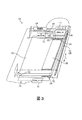
図2には、筺体を有する3次元プリンタが示されている。このプリンタ60は筺体64を有する。筺体64の内部は、ほぼ立方体形状の6つのコンパートメントに分けられている。図2では、この筺体64はドアを省略して示されており、このドアを閉めることによりコンパートメントは隠される。コンパートメント72は、移動可能なプラットフォーム82の上に載った平面支持体78を含む。移動可能なプラットフォーム82は1つ以上のアクチュエータおよびガイド部材(図示せず)と共に構成され、この構成により、移動可能なプラットフォーム82は、垂直方向の上下移動が可能になる。この平面支持体78の表面に、3次元の物体が形成される。いくつかの実施形態では、この印刷ヘッド86は、コンパートメント72の後壁からコンパートメントの表面の開口の方向で、平面支持体78の長さとほぼ同じ長さを有する。これらの実施形態では、印刷ヘッド86は、直線の往復移動だけを行えばいいよう、筺体64の側壁96と側壁100の間の空間の支持部材92に取り付けられる。他の実施形態では、印刷ヘッド86は、コンパートメント72の後壁からコンパートメントの表面の開口への方向で、平面支持体78の長さより短い長さを有する。これらの実施形態では、印刷ヘッド86は、コンパートメント72の上の平面の2つの直交する方向で往復移動を行うよう、筺体64の側壁96と側壁100の間の空間の支持部材92に取り付けられる。これらの種々の実施形態では、1つ以上のアクチュエータ104が、印刷ヘッド86に動作可能に接続する。制御装置108はアクチュエータ104を操作して、印刷ヘッド86を支持部材92上で直線的に往復移動させる、あるいは印刷ヘッドを平面の2つの直交する方向に移動させる。印刷ヘッド86内のインクジェットを選択的に操作し、支持プラットフォーム82を垂直方向に移動させ、支持部材92に載った印刷ヘッド86を水平方向に移動させることにより、平面支持体78上で3次元の物体を形成することができる。
FIG. 2 shows a three-dimensional printer having a housing. The printer 60 has a housing 64. The interior of the housing 64 is divided into six compartments having a substantially cubic shape. In FIG. 2, the housing 64 is shown with the door omitted, and the compartment is hidden by closing the door.
図2の点線で輪郭のみ示されている領域112は、光透過性の下地を用いてプリンタ60の動作不能インクジェットを検知するモジュールの配置位置を示している。上記の通り、物体の印刷中に、インクジェットが、完全にまたは部分的に材料を吐出しなくなることにより、あるいは傾いた方向で不規則に材料を吐出することにより故障した場合、製造される物体は変形する。現在、このような変形は、物体の製造が完了するまで検知することはできない。以下により詳しく説明する通り、光透過性の下地上に吐出された材料を光学的に検知する領域112を用いることにより、プリンタ60は、物体の製造中に動作不能インクジェットを検知するよう構成され得る。モジュール300内のいくつかの構成部品は、図で示される、横方向H、奥行き方向D、および垂直方向Vに移動可能である。
A
図3のブロック図には、物体の印刷中に透明な材料を吐出して、動作不能インクジェットを検知するモジュールの一実施形態が示されている。このモジュール300は、プリンタ60の領域112内に嵌合するよう構成されている。このモジュール300は、光学センサ304、光透過性の下地308、下地搬送部312、光源314、1つ以上のアクチュエータ316、クリーニング部材320、制御装置324、および廃棄物容器328を含む。光学センサ304は、アクチュエータ316により、WおよびLの両方向で双方向に移動するよう構成されている。この構成により、光学センサ304は、搬送部312のエンドレスベルト330の表面の上を移動することができる。搬送部312は、ローラ332の周りに巻き付いたエンドレスベルト330を含む。アクチュエータ316は、ローラ332を駆動させてベルトを双方向に回し、下地308を印刷位置に移動させ、その後、クリーニング可能な位置に移動させる。制御装置324はアクチュエータ316に操作可能に接続して、光学センサ304を移動させ、ローラ332を駆動させてベルト312と共に光透過性の下地308を移動させ、クリーニング部材320を用いて光透過性の下地308を掃く。いくつかの実施形態では、センサの幅が少なくとも下地308と同じであれば、光学センサ304を方向Lで双方向に移動するよう構成するだけでよい。
The block diagram of FIG. 3 illustrates one embodiment of a module that detects inoperable inkjets by ejecting a transparent material during object printing. The
光透過性の下地308は、印刷ヘッド86から吐出される造形材料および支持材料を支持し、下地の縁に沿って下地内に入る光を内部全反射させる材料から作られた平面部材である。下地の表面の上の特定の材料により、その材料と平坦な表面の境界での内部全反射特性が変化しない限り、これらの材料は下地の縁に沿って入る光を平面の下地内に留めることができる。約1.3〜約1.5の範囲の屈折率を有する材料またはインクを吐出するプリンタに対して、光透過性の下地は、一般に、約1.4〜約1.8の範囲の屈折率を有する。例えば、この平面の下地は、基本的には、ポリカーボネート、アクリル、またはガラスから成り得る。下地が印刷される際、下地の平坦な表面上に吐出された材料と下地の間の屈折率が同様であれば、下地と材料の境界に対する入射角が浅くても、光は下地を伝播し材料内に入ることができる。材料内の光は、下地上の材料の内部表面に対して急な入射角を有するため、その光は周囲の空気中に放出され得る。光の他の部分は、内部反射を数回繰り返し最終的に材料から出る。材料に覆われていない表面からは光が放出されず、材料から放出される光により、明暗比がうまく積み重ねられるため、この放出される光により、光透過性の下地の平坦な表面上での材料の位置が可視的に表示される。センサ304が下地308の上を通過するとき、センサ304は電気信号を生成し、この電気信号により下地308上のテストパターンの画像データが形成される。
The light-transmitting
図4には、3次元の物体を作成するプリンタを動作させる方法が示されている。この方法の説明では、処理があるタスクまたは機能を実行するという記載は、制御装置すなわち汎用プロセッサが、この制御装置すなわちプロセッサに動作可能に接続するメモリに格納されたプログラム命令を実行して、データを処理すること、あるいはプリンタ内の1つ以上の構成部品を動作させてタスクまたは機能を実行することを指す。上記に記載した制御装置324は、そのような制御装置すなわちプロセッサでよい。あるいは、制御装置324は、本明細書に記載される1つ以上のタスクまたは機能を実行するようそれぞれ構成される、複数のプロセッサならびに関連する回路および構成部品を用いて実装可能である。
FIG. 4 shows a method of operating a printer that creates a three-dimensional object. In the description of this method, the statement that a process performs a task or function means that a control unit or general-purpose processor executes program instructions stored in a memory operatively connected to the control unit or processor to execute data , Or operating one or more components in a printer to perform a task or function. The
印刷動作中の所定の時間で、制御装置108(図2)がアクチュエータ104を操作して、印刷ヘッド86を領域112内に配置されたモジュール300内に移動させる(ブロック404)。制御装置324がモジュール300内で印刷ヘッドを検知すると、この制御装置324は搬送部312を操作して、光透過性の下地308を印刷ヘッド86の向かい側に移動させる(ブロック408)。次いで、制御装置324は信号を生成して制御装置108に送信し、印刷ヘッド内のインクジェットを動作させて下地308上にテストパターンを印刷させる(ブロック412)。ある実施形態では、印刷ヘッド内の各インクジェットが繰り返して動作し、インクジェットの向かい側の下地308の部分に材料のパイル(テストドットとも呼ばれる)を形成する。テストパターンを印刷した後、制御装置108は、印刷ヘッド86をモジュール300の外に移動させ、制御装置324用の信号を生成する。制御装置108からの信号に応じて、制御装置324はアクチュエータ316を操作して、光学センサ304を下地308の上のテストパターンの向かい側の位置に移動させる(ブロック416)。この移動は、下地308が印刷されたモジュールの側に光学センサを移動させることにより行われる、あるいは、アクチュエータにより駆動させるローラ332を操作して下地を光学センサが位置する側に移動させることにより行われる。次いで、制御装置324は、光源314を起動させて、一方の縁から下地308に光を当てる(ブロック418)。この図では、光源が、この図で示される右側の縁の下地308の縁から、方向Lに延在する光を入射させているが、その他の3つの縁のどの縁に光を当ててもよい。光源314は、発光ダイオード(LED)のアレイ、レーザダイオードのアレイ、冷陰極蛍光灯、フィラメントなどでよい。これらのアレイは、1次元(すなわち線形)のアレイ、または2次元のアレイでよい。光源314により発光される光は、赤外線、紫外線、多色光、または単色光でよい。下地内に光を入射させることができるよう、光源を下地から離すことができる、あるいは、下地に取り付けることができる。続いてこの処理は、アクチュエータを操作して、光学センサ304を下地308の上で方向Lに移動させて電気信号を生成し、この電気信号を下地308の平坦な表面の画像データとして制御装置324に供給する(ブロック420)。造形材料と支持材料が吐出された領域は、上記に説明した通り光を放出する。光を内部に反射させる表面部および光を放出させる表面部は、造形材料および支持材料を吐出するために用いられるテストパターンに対応していなければならない。テストパターンを形成するために用いられる造形材料および支持材料の予想される位置を参照し、平坦な表面の画像データを分析して、動作不能インクジェットを特定し(ブロック424)、動作不能インクジェットが特定された場合、不良の印刷ヘッドを示す信号を、プリンタの操作者用に生成する(ブロック428)。次いで、操作者が適切な動作を行うことができる。印刷された位置に下地の画像が形成されている場合、処理は続き、制御装置324がアクチュエータ316を操作して搬送部312を逆に回し、下地をそのスタート位置に戻す(ブロック432)。そうでない場合には、下地は既にクリーニングの位置に配置されている。制御装置324がアクチュエータ316を操作して、クリーニング部材320に下地308を係合させ、クリーニング部材320を方向Lに動かして、下地から材料を取り除く(ブロック436)。取り除かれた材料は廃棄物容器328内に回収される。図面では、この廃棄物容器328はエンドレスベルト330の前端部に配置されているが、クリーニング部材が移動する位置および方向を用いてもよい。この容器328は、ときどきプリンタから取り外し、交換することができる、あるいは空にして再度取り付けることができる。印刷された位置に下地の画像が形成されている場合、制御装置324がアクチュエータ316を操作して、下地308の上の位置に光学センサ304を戻す(ブロック440)。
At a predetermined time during the printing operation, the controller 108 (FIG. 2) operates the
いくつかの実施形態では、続いて図4の処理は、下地のクリーニングの評価を行う。これらの実施形態では、制御装置は、クリーナが下地の表面から材料を取り除いた後、光源を起動させ(ブロック444)、光学センサを下地の上に移動させてクリーニングされた下地の画像データを生成する(ブロック448)。下地の表面で材料が存在するところだけ光が放出されるため、これらの画像データを所定の閾値と比較して下地から放出された光が閾値を超えているか確認する(ブロック452)。閾値を超えている場合、光学センサから受け取られた画像データにノイズが存在する。ノイズが検知されると、クリーニング動作をさらに行い(ブロック436〜440)、クリーニングの結果を再度評価する(ブロック444〜452)。現在のテストで下地のクリーニングを2回以上行った場合(ブロック456)、下地の少なくとも一部の画像データを制御装置に動作可能に接続するメモリに格納する(ブロック460)。ノイズの干渉を受けないでテストパターンの確認を可能にするために、次に印刷ヘッドをテストしたときに得られる画像データからこれらのノイズデータを取り除き、これにより、制御装置は動作不能のインクジェットを検知することができる。
In some embodiments, the process of FIG. 4 subsequently evaluates the cleaning of the substrate. In these embodiments, the controller activates the light source after the cleaner removes material from the substrate surface (block 444) and moves the optical sensor over the substrate to generate cleaned substrate image data. (Block 448). Since light is emitted only where the material exists on the surface of the base, these image data are compared with a predetermined threshold value to check whether the light emitted from the base exceeds the threshold value (block 452). If the threshold is exceeded, there is noise in the image data received from the optical sensor. When noise is detected, the cleaning operation is further performed (
クリーニング部材320は、アクチュエータ316に動作可能に接続する支持部材348に取り付けられている。上記の通り、制御装置324がアクチュエータを操作して、支持部材348を動かして、クリーニング部材320で下地308をスワイプする。この動作により、造形材料および支持材料を下地308から廃棄物容器328に掃き取り、次のテストパターンの印刷のために下地の表面を新しくする。クリーニング部材320は、クリーニング溶剤の供給器340を含むことができ、この供給器340は、クリーニング部材が下地を掃く前に、下地の上にクリーニング溶剤を分散させるよう構成されている。このクリーニング溶剤が、造形材料および支持材料と化学的に反応し、クリーニング部材を当てる前にこれらの材料を柔らかくする。さらに、または、あるいは、ヒータ344が、ヒータと電源を選択的に接続する制御装置に動作可能に接続することができる。このヒータは、クリーニング部材320に対して配置され、クリーニング部材が下地308を掃く前に造形材料および支持材料を加熱する。
The cleaning
上記に議論した実施形態は、3次元の物体を形成するプリンタ内で用いられているが、このような下地から放出される光により動作不能インクジェットを検知する光透過性の下地およびシステムは、2次元の文書印刷システム、具体的には、透明なインクを用いる文書印刷システムでも使用可能である。したがって、本明細書で使用される用語「材料」とは、3次元の物体を形成するために使用可能な物質、および文書印刷で使用されるインクのことを指す。文書印刷システムでは、光透過性の下地をプリンタ内の印刷ゾーンに隣接させて配置することができ、下地の上にインクを吐出させるために、ときどき印刷ヘッドを下地の向かい側に移動させる。次いで、光を下地に入射させ下地上に画像を形成し、これにより、画像データを分析して、動作不能インクジェットを特定することができる。同様に、移動ウェブまたはドラムなどの画像形成部材に透明なインクを吐出する印刷ヘッドを光透過性の下地の向かい側に移動させて、印刷を行い、動作不能インクジェットを検知することができる。 While the embodiments discussed above are used in printers that form three-dimensional objects, light transmissive substrates and systems that detect inoperable inkjets with light emitted from such substrates are two. It can also be used in a three-dimensional document printing system, specifically, a document printing system using transparent ink. Thus, as used herein, the term “material” refers to materials that can be used to form three-dimensional objects and inks used in document printing. In document printing systems, a light transmissive substrate can be placed adjacent to a print zone in a printer, and sometimes the print head is moved across the substrate to eject ink onto the substrate. The light is then incident on the substrate to form an image on the substrate, which can analyze the image data to identify inoperable inkjets. Similarly, printing can be performed by moving a print head that discharges transparent ink onto an image forming member such as a moving web or a drum to the opposite side of the light-transmitting base, and inoperable inkjet can be detected.
Claims (19)
表面を有し、自身の外周に沿って縁を有する下地と、
前記下地の前記表面に材料を吐出するよう構成される印刷ヘッドと、
前記下地の前記縁に光を当てるよう配置される光源と、
前記下地の前記表面に吐出された前記材料から放出される光を受け取るよう配置される光学センサであって、前記下地の前記表面および前記下地の前記表面に吐出された前記材料に対応する画像データを生成するよう構成される光学センサと、
前記印刷ヘッド、前記光源、および前記光学センサに操作可能に接続する制御装置であって、前記印刷ヘッドを操作して、所定のパターンに従って、前記下地の前記表面に材料を吐出し、前記光源を選択的に起動させ、前記光源が前記下地の前記縁に光を当てている間に、前記光学センサにより生成される画像データを受け取り、前記受け取られた画像データおよび前記所定のパターンを参照して、前記印刷ヘッド内の動作不能インクジェットを検知するよう構成される制御装置と、を含むプリンタ。 A printer for forming an object,
A base having a surface and having an edge along its outer periphery;
A print head configured to eject material onto the surface of the substrate;
A light source arranged to shine light on the edge of the substrate;
An optical sensor arranged to receive light emitted from the material ejected onto the surface of the base, the image data corresponding to the surface of the base and the material ejected onto the surface of the base An optical sensor configured to generate
A control device operably connected to the print head, the light source, and the optical sensor, wherein the print head is operated to discharge a material onto the surface of the base according to a predetermined pattern, Selectively activating and receiving image data generated by the optical sensor while the light source illuminates the edge of the substrate, with reference to the received image data and the predetermined pattern And a control device configured to detect inoperable ink jets in the print head.
前記制御装置が、前記クリーナに操作可能に接続し、前記制御装置が前記クリーナを操作して、前記下地の前記表面の前記少なくとも一部から材料を取り除くようさらに構成される、請求項1に記載のプリンタ。 Further comprising a cleaner configured to remove material from at least a portion of the surface of the substrate;
The controller of claim 1, wherein the controller is operably connected to the cleaner, and the controller is further configured to operate the cleaner to remove material from the at least part of the surface of the substrate. Printer.
前記下地の前記表面の前記少なくとも一部と係合し、前記表面の前記少なくとも一部に対して移動するよう構成される部材と、
前記部材および前記制御装置と動作可能に接続するアクチュエータであって、前記制御装置が前記アクチュエータを操作して、前記下地の前記表面の前記少なくとも一部に対して前記部材を移動させることができる、アクチュエータと、をさらに含む、請求項9に記載のプリンタ。 The cleaner is
A member configured to engage with and move relative to the at least part of the surface of the substrate;
An actuator operably connected to the member and the control device, wherein the control device can operate the actuator to move the member relative to the at least part of the surface of the substrate; The printer according to claim 9, further comprising an actuator.
溶剤の供給器に動作可能に接続する塗布器をさらに含み、
前記制御装置が、前記塗布器を操作して、前記下地の前記表面の前記少なくとも一部に溶剤を塗布して、前記下地の前記表面の前記少なくとも一部から材料を取り除くようさらに構成される、請求項9に記載のプリンタ。 The cleaner is
Further comprising an applicator operably connected to the solvent supply;
The controller is further configured to operate the applicator to apply a solvent to the at least a portion of the surface of the substrate to remove material from the at least a portion of the surface of the substrate; The printer according to claim 9.
前記下地の前記表面の前記少なくとも一部を加熱するよう配置されるヒータをさらに含み、
前記制御装置が、前記ヒータを操作して、前記下地の前記表面の前記少なくとも一部を加熱し、前記下地の前記表面の前記少なくとも一部から材料を取り除くようさらに構成される、請求項9に記載のプリンタ。 The cleaner is
Further comprising a heater arranged to heat the at least part of the surface of the substrate;
10. The controller of claim 9, further configured to operate the heater to heat the at least part of the surface of the foundation and remove material from the at least part of the surface of the foundation. The printer described.
The substrate has a refractive index in the range of about 1.4 to about 1.8, and the material ejected by the print head has a refractive index in the range of about 1.3 to about 1.5. Item 2. The printer according to Item 1.
Applications Claiming Priority (2)
| Application Number | Priority Date | Filing Date | Title |
|---|---|---|---|
| US14/231,251 | 2014-03-31 | ||
| US14/231,251 US9079440B1 (en) | 2014-03-31 | 2014-03-31 | System for detecting inoperative inkjets in printheads ejecting clear ink using a light transmitting substrate |
Publications (3)
| Publication Number | Publication Date |
|---|---|
| JP2015196382A JP2015196382A (en) | 2015-11-09 |
| JP2015196382A5 JP2015196382A5 (en) | 2018-04-12 |
| JP6376998B2 true JP6376998B2 (en) | 2018-08-22 |
Family
ID=53506639
Family Applications (1)
| Application Number | Title | Priority Date | Filing Date |
|---|---|---|---|
| JP2015052712A Active JP6376998B2 (en) | 2014-03-31 | 2015-03-16 | A system for detecting inoperable inkjets in a print head that ejects a transparent material using a light transmissive substrate |
Country Status (5)
| Country | Link |
|---|---|
| US (1) | US9079440B1 (en) |
| JP (1) | JP6376998B2 (en) |
| KR (1) | KR102208289B1 (en) |
| CN (1) | CN104943165B (en) |
| DE (1) | DE102015205238B4 (en) |
Families Citing this family (11)
| Publication number | Priority date | Publication date | Assignee | Title |
|---|---|---|---|---|
| JP6428049B2 (en) * | 2014-08-25 | 2018-11-28 | 富士ゼロックス株式会社 | Additive manufacturing apparatus and additive manufacturing program |
| US10005229B2 (en) * | 2015-08-31 | 2018-06-26 | Xerox Corporation | System for using optical sensor focus to identify feature heights on objects being produced in a three-dimensional object printer |
| US9993977B2 (en) * | 2015-10-01 | 2018-06-12 | Xerox Corporation | System for using an optical sensor array to monitor color fidelity in objects produced by a three-dimensional object printer |
| US10011078B2 (en) | 2015-10-01 | 2018-07-03 | Xerox Corporation | System for using multiple optical sensor arrays to measure features on objects produced in a three-dimensional object printer |
| GB2549071B (en) * | 2016-03-23 | 2020-11-11 | Sony Interactive Entertainment Inc | 3D printing system |
| US10155398B1 (en) * | 2017-11-27 | 2018-12-18 | Xerox Corporation | System and method for identifying a location for printing an image on an object and operating printheads to print the image on the object |
| CN107953546B (en) * | 2017-12-07 | 2019-11-08 | 徐素香 | A method of improving stock utilization |
| CN108381929A (en) * | 2018-03-05 | 2018-08-10 | 上海联泰科技股份有限公司 | Control method and the 3D printing equipment being applicable in |
| US10739675B2 (en) * | 2018-05-31 | 2020-08-11 | Canon Kabushiki Kaisha | Systems and methods for detection of and compensation for malfunctioning droplet dispensing nozzles |
| US11518092B2 (en) * | 2019-06-19 | 2022-12-06 | Xerox Corporation | Patterned pre-stop for finishing additive manufactured 3D objects |
| CN115384189B (en) * | 2022-10-28 | 2023-04-07 | 季华实验室 | Device and method for observing and counting drop points of ink drops of spray head |
Family Cites Families (9)
| Publication number | Priority date | Publication date | Assignee | Title |
|---|---|---|---|---|
| US6007318A (en) | 1996-12-20 | 1999-12-28 | Z Corporation | Method and apparatus for prototyping a three-dimensional object |
| US7037382B2 (en) | 1996-12-20 | 2006-05-02 | Z Corporation | Three-dimensional printer |
| JP2001334582A (en) * | 2000-05-24 | 2001-12-04 | Minolta Co Ltd | Three-dimensional molding apparatus and three- dimensional molding process |
| WO2004024447A2 (en) | 2002-09-12 | 2004-03-25 | Objet Geometries Ltd. | Device, system and method for calibration in three-dimensional model printing |
| KR100750131B1 (en) * | 2005-09-23 | 2007-08-21 | 삼성전자주식회사 | Apparatus and method for testing nozzle |
| US8784723B2 (en) | 2007-04-01 | 2014-07-22 | Stratasys Ltd. | Method and system for three-dimensional fabrication |
| JP2009220394A (en) | 2008-03-17 | 2009-10-01 | Toppan Printing Co Ltd | Inkjet discharge inspection device |
| US8579620B2 (en) * | 2011-03-02 | 2013-11-12 | Andy Wu | Single-action three-dimensional model printing methods |
| CN103594045B (en) * | 2013-11-01 | 2016-03-02 | 浙江大学 | A kind of method based on 3D printing and making stereo luminous character and device |
-
2014
- 2014-03-31 US US14/231,251 patent/US9079440B1/en active Active
-
2015
- 2015-03-12 CN CN201510109444.3A patent/CN104943165B/en active Active
- 2015-03-16 JP JP2015052712A patent/JP6376998B2/en active Active
- 2015-03-17 KR KR1020150036569A patent/KR102208289B1/en active IP Right Grant
- 2015-03-23 DE DE102015205238.9A patent/DE102015205238B4/en active Active
Also Published As
| Publication number | Publication date |
|---|---|
| US9079440B1 (en) | 2015-07-14 |
| KR102208289B1 (en) | 2021-01-26 |
| DE102015205238B4 (en) | 2024-01-04 |
| KR20150113840A (en) | 2015-10-08 |
| CN104943165B (en) | 2018-06-19 |
| JP2015196382A (en) | 2015-11-09 |
| CN104943165A (en) | 2015-09-30 |
| DE102015205238A1 (en) | 2015-10-01 |
Similar Documents
| Publication | Publication Date | Title |
|---|---|---|
| JP6376998B2 (en) | A system for detecting inoperable inkjets in a print head that ejects a transparent material using a light transmissive substrate | |
| JP6336936B2 (en) | System for detecting inoperable inkjets during printing of a three-dimensional object using an optical sensor and a reversible thermal substrate | |
| US9221248B2 (en) | System for detecting inoperative inkjets in printheads ejecting clear ink using a rotating member having a light transmitting surface | |
| JP6385301B2 (en) | System for detecting an inoperable inkjet during printing of a three-dimensional object using a test pattern and an electrical continuity test probe | |
| JP6391506B2 (en) | Printer and device | |
| US9302519B1 (en) | System for detecting malfunctioning ejectors in three-dimensional object printing using specular reflectance | |
| JP2015196382A5 (en) | ||
| JP2007076084A (en) | Printer, and printing method | |
| US9352572B2 (en) | System for detecting inoperative inkjets in three-dimensional object printing using an optical sensor and movable test substrates | |
| US9415600B2 (en) | System for detecting inoperative inkjets in three-dimensional object printing using a digital camera and strobe light | |
| JP6466215B2 (en) | A system that detects inoperable inkjets in a print head that ejects transparent ink using a thermal substrate. | |
| JP2009274846A (en) | Existence detection system of recording material, existence detection method of recording material and recorder | |
| US9090113B1 (en) | System for detecting inoperative ejectors in three-dimensional object printing using a pneumatic sensor | |
| US10688773B2 (en) | Cure confirmation system and method for three dimensional object printer | |
| JP2015047800A (en) | Liquid detection member, liquid discharge device, and production method of the liquid detection member | |
| JP5082225B2 (en) | Printing apparatus and printing method | |
| JP2014079894A (en) | Image forming device |
Legal Events
| Date | Code | Title | Description |
|---|---|---|---|
| A521 | Request for written amendment filed |
Free format text: JAPANESE INTERMEDIATE CODE: A523 Effective date: 20180228 |
|
| A621 | Written request for application examination |
Free format text: JAPANESE INTERMEDIATE CODE: A621 Effective date: 20180228 |
|
| A871 | Explanation of circumstances concerning accelerated examination |
Free format text: JAPANESE INTERMEDIATE CODE: A871 Effective date: 20180228 |
|
| A975 | Report on accelerated examination |
Free format text: JAPANESE INTERMEDIATE CODE: A971005 Effective date: 20180308 |
|
| A131 | Notification of reasons for refusal |
Free format text: JAPANESE INTERMEDIATE CODE: A131 Effective date: 20180417 |
|
| A521 | Request for written amendment filed |
Free format text: JAPANESE INTERMEDIATE CODE: A523 Effective date: 20180625 |
|
| TRDD | Decision of grant or rejection written | ||
| A01 | Written decision to grant a patent or to grant a registration (utility model) |
Free format text: JAPANESE INTERMEDIATE CODE: A01 Effective date: 20180710 |
|
| A61 | First payment of annual fees (during grant procedure) |
Free format text: JAPANESE INTERMEDIATE CODE: A61 Effective date: 20180724 |
|
| R150 | Certificate of patent or registration of utility model |
Ref document number: 6376998 Country of ref document: JP Free format text: JAPANESE INTERMEDIATE CODE: R150 |
|
| R250 | Receipt of annual fees |
Free format text: JAPANESE INTERMEDIATE CODE: R250 |
|
| R250 | Receipt of annual fees |
Free format text: JAPANESE INTERMEDIATE CODE: R250 |
|
| R250 | Receipt of annual fees |
Free format text: JAPANESE INTERMEDIATE CODE: R250 |