JP6375673B2 - Ignition device - Google Patents
Ignition device Download PDFInfo
- Publication number
- JP6375673B2 JP6375673B2 JP2014080626A JP2014080626A JP6375673B2 JP 6375673 B2 JP6375673 B2 JP 6375673B2 JP 2014080626 A JP2014080626 A JP 2014080626A JP 2014080626 A JP2014080626 A JP 2014080626A JP 6375673 B2 JP6375673 B2 JP 6375673B2
- Authority
- JP
- Japan
- Prior art keywords
- secondary current
- ignition
- circuit
- detected value
- control
- Prior art date
- Legal status (The legal status is an assumption and is not a legal conclusion. Google has not performed a legal analysis and makes no representation as to the accuracy of the status listed.)
- Expired - Fee Related
Links
Images
Landscapes
- Ignition Installations For Internal Combustion Engines (AREA)
Description
本発明は、内燃機関(エンジン)に用いられる点火装置に関する。 The present invention relates to an ignition device used for an internal combustion engine (engine).
点火プラグの負担を軽減し、無駄な電力消費を抑えて、火花放電を継続させる技術として、次のエネルギー投入回路を考案した(詳細は特願2013−082958参照。この技術は非公知である。)。エネルギー投入回路は、いわゆるフルトラ型の点火回路によって開始した火花放電(以下、主点火と呼ぶ。)が消える前に1次コイルのマイナス側から電気エネルギーを投入し、主点火と同一方向の2次電流を継続して流すことで、主点火として生じた火花放電を任意の期間に亘って継続させるものである。
なお、以下では、エネルギー投入回路により継続させる火花放電、つまり、主点火に続く火花放電を継続火花放電と呼ぶ。また、継続火花放電が続く期間を放電継続期間と呼ぶ。
The following energy input circuit has been devised as a technique for reducing the burden on the spark plug, suppressing unnecessary power consumption, and continuing the spark discharge (for details, see Japanese Patent Application No. 2013-082958. This technique is not known). ). The energy input circuit supplies electric energy from the negative side of the primary coil before the spark discharge (hereinafter referred to as main ignition) started by a so-called full-trait ignition circuit disappears, and the secondary in the same direction as the main ignition. By causing the current to flow continuously, the spark discharge generated as the main ignition is continued for an arbitrary period.
Hereinafter, the spark discharge that is continued by the energy input circuit, that is, the spark discharge following the main ignition is referred to as a continuous spark discharge. Further, a period in which the continuous spark discharge continues is called a discharge continuation period.
エネルギー投入回路は、放電継続期間中の1次電流を制御することで、2次電流を調節して火花放電の維持を行う。また、継続火花放電中の2次電流を調節することで、点火プラグの負担を軽減し、且つ無駄な電力消費を抑えて、火花放電を継続することができる。
さらに、装置個体差、経年劣化および放電環境の多様性等に影響されず火花放電を安定して継続させるため、2次電流を検出してエネルギー投入回路にフィードバックするフィードバック回路を追加した構成を考案した(特願2013−246091参照。この技術は非公知である。)。
The energy input circuit controls the primary current during the discharge duration to adjust the secondary current and maintain the spark discharge. In addition, by adjusting the secondary current during the continuous spark discharge, it is possible to reduce the burden on the spark plug, suppress unnecessary power consumption, and continue the spark discharge.
Furthermore, in order to keep the spark discharge stable without being affected by individual device differences, aging deterioration, and the variety of discharge environments, a configuration was added to add a feedback circuit that detects the secondary current and feeds it back to the energy input circuit. (See Japanese Patent Application No. 2013-246091. This technique is not publicly known.)
次に、本発明の理解補助の目的で、本発明を適用していないエネルギー投入回路の代表例を図6に基づき説明する。
図6に示す点火装置100は、フルトラに基づく主点火を点火プラグ101に生じさせる主点火回路102と、主点火に継続させて継続火花放電を生じさせるエネルギー投入回路103とを備える。
Next, for the purpose of assisting understanding of the present invention, a representative example of an energy input circuit to which the present invention is not applied will be described with reference to FIG.
The
主点火回路102は、スイッチング素子104のオンによって車載バッテリ105から1次コイル106にプラスの1次電流を通電させて磁気エネルギーを蓄えさせ、その後、スイッチング素子104のオフにより、電磁誘導によって磁気エネルギーを電気エネルギーに変換して2次コイル107に高電圧を発生させ、主点火を生じさせる。また、エネルギー投入回路103は、昇圧回路108において車載バッテリ105の電圧を昇圧してコンデンサ109に蓄えるとともに、スイッチング素子110のオンオフにより、コンデンサ109に蓄えた電気エネルギーを1次コイル106のマイナス側に投入する。
When the
また、図6に示す点火装置100は、2次電流を検出してエネルギー投入回路103にフィードバックするフィードバック回路111を備え、フィードバック回路111は、検出した2次電流をエネルギー投入回路103のドライバ回路にフィードバックする。
The
(問題点)
点火装置の故障等により、継続火花放電中の2次電流が異常な数値になった場合、以下のような事態になる虞がある。すなわち、継続火花放電中の2次電流が過小である場合、エネルギー投入回路によるエネルギー投入量が過小になってエンジン失火に至る可能性がある。逆に、継続火花放電中の2次電流が過大である場合、継続して使用するとエネルギー投入量が過大になって更なる故障に至る可能性がある。そこで、エネルギー投入回路の動作時に2次電流の異常を判定する手段が必要となっている。
(problem)
If the secondary current during continuous spark discharge becomes an abnormal value due to a failure of the ignition device, the following situation may occur. That is, when the secondary current during continuous spark discharge is too small, the amount of energy input by the energy input circuit may be too small, leading to engine misfire. On the other hand, if the secondary current during continuous spark discharge is excessive, continued use may result in excessive energy input and further failure. Therefore, a means for determining an abnormality of the secondary current during the operation of the energy input circuit is required.
(参考技術)
一方、本発明に関連する技術として、点火プラグの放電時間に基づき燃焼室内の「乱れ強度」を推定するとともに、推定結果に応じてエンジンの燃焼状態が安定領域にあるか否かを判定して「乱れ強度」を低下させる技術が公知である(特許文献1参照)。
しかし、特許文献1の技術は、点火プラグの放電時間を利用して燃焼室内の乱れを修正する技術に関わるものであり、2次電流の異常に関わるものではない。
(Reference technology)
On the other hand, as a technique related to the present invention, the “turbulence intensity” in the combustion chamber is estimated based on the discharge time of the spark plug, and whether or not the combustion state of the engine is in a stable region is determined according to the estimation result. A technique for reducing the “turbulence intensity” is known (see Patent Document 1).
However, the technique of Patent Document 1 relates to a technique for correcting the disturbance in the combustion chamber using the discharge time of the spark plug, and does not relate to an abnormality in the secondary current.
本発明は、上記問題点に鑑みてなされたものであり、その目的は、エネルギー投入回路を備える内燃機関用の点火装置において、エネルギー投入回路の動作時に2次電流の異常を判定する手段を提供することにある。 The present invention has been made in view of the above problems, and an object of the present invention is to provide means for determining an abnormality in a secondary current when the energy input circuit is operated in an ignition device for an internal combustion engine including the energy input circuit. There is to do.
本願の第1発明の内燃機関用の点火装置は、次の主点火回路、エネルギー投入回路、2次電流検出手段、電流検出回路および異常判定部を備える。
主点火回路は、点火コイルの1次コイルの通電制御を行って点火プラグに火花放電を生じさせる。また、エネルギー投入回路は、主点火回路の動作によって開始した火花放電中に、1次コイルの通電制御を行って、点火コイルの2次コイルに同一方向の2次電流を継続して流し、主点火回路の動作によって開始した火花放電を継続させる。また、2次電流検出手段は2次電流を検出する。また、電流検出回路は、エネルギー投入回路の動作時の2次電流の検出値に対し、絶対値としての上限、下限それぞれの閾値である制御上限(H)、制御下限(L)を設定するとともに、これら制御上限(H)、制御下限(L)と検出値との比較に基づき、エネルギー投入回路による通電制御を行うためのフィードバック信号を出力する。
The ignition device for an internal combustion engine of the first invention of the present application includes the following main ignition circuit, energy input circuit, secondary current detection means , current detection circuit, and abnormality determination unit.
The main ignition circuit performs energization control of the primary coil of the ignition coil to cause spark discharge in the spark plug. The energy input circuit performs energization control of the primary coil during the spark discharge started by the operation of the main ignition circuit, and continuously supplies a secondary current in the same direction to the secondary coil of the ignition coil. The spark discharge started by the operation of the ignition circuit is continued. Further, the secondary current detecting means detects the secondary current. The current detection circuit sets an upper limit and a lower limit of the control upper limit (H) and the control lower limit (L), which are upper and lower limits as absolute values, for the detected value of the secondary current during operation of the energy input circuit. Based on the comparison between the control upper limit (H) and the control lower limit (L) and the detected value, a feedback signal for performing energization control by the energy input circuit is output.
そして、異常判定部は、エネルギー投入回路の動作時の2次電流の検出値に対し、制御上限(H)よりも絶対値として大きい許容上限(HH)、および、制御下限(L)よりも絶対値として小さい許容下限(LL)により画される許容範囲を設定するとともに、2次電流の検出値が許容範囲を外れたか否かを判定する。
これにより、2次電流の検出値が許容範囲を外れたことを検知することができる。このため、エネルギー投入回路の動作時に2次電流の異常を判定することができる。さらに、異常と判定した場合には、異常信号を出力してユーザに報知することで、更なる故障を防止することができる。
Then, abnormality determination unit, against the detected value of the operating time of the secondary current of the energy input circuit, a large allowable upper absolute value than the control upper (H) (HH), and, than the control lower limit (L) An allowable range defined by a small allowable lower limit (LL) is set as an absolute value, and it is determined whether or not the detected value of the secondary current is out of the allowable range.
Thereby, it can be detected that the detected value of the secondary current is out of the allowable range. For this reason, the abnormality of the secondary current can be determined during the operation of the energy input circuit. Furthermore, when it determines with abnormality, it can prevent a further failure by outputting an abnormal signal and alerting | reporting to a user.
本願の第1発明に従属する第2発明によれば、異常判定部は、許容範囲を2次電流の指令値に応じて変更する。
これにより、指令値の変更に伴う誤判定を防止することができる。
According to the second invention subordinate to the first invention of the present application, the abnormality determination unit changes the allowable range according to the command value of the secondary current.
Thereby, the erroneous determination accompanying the change of the command value can be prevented.
以下において、発明を実施するための形態を、実施例を用いて説明する。なお、実施例は具体的な一例を開示するものであり、本発明が実施例に限定されないことは言うまでもない。 Hereinafter, modes for carrying out the invention will be described using examples. In addition, an Example discloses a specific example, and it cannot be overemphasized that this invention is not limited to an Example.
〔実施例1の構成〕
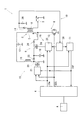
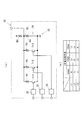
図1を参照して実施例1の点火装置1を説明する。
点火装置1は、車両走行用の火花点火エンジンに搭載されるものであり、所定の点火時期に燃焼室内の混合気に点火するものである。なお、エンジンの一例は、ガソリンを燃料とする希薄燃焼(リーンバーン)が可能な直噴式エンジンであり、気筒内にタンブル流やスワール流等の混合気の旋回流を生じさせる旋回流コントロール手段を備える。そして、リーンバーンのように気筒内のガス流速が高く火花放電の吹き消え発生の可能性がある運転状態において、点火装置1は、主点火に続けて継続火花放電を行うように制御される。
[Configuration of Example 1]
The ignition device 1 according to the first embodiment will be described with reference to FIG.
The ignition device 1 is mounted on a spark ignition engine for running a vehicle, and ignites an air-fuel mixture in a combustion chamber at a predetermined ignition timing. An example of the engine is a direct injection engine capable of lean burn using gasoline as fuel, and a swirl flow control means for generating a swirl flow of an air-fuel mixture such as a tumble flow or a swirl flow in a cylinder. Prepare. In an operating state where the gas flow rate in the cylinder is high and there is a possibility that the spark discharge is blown out, such as lean burn, the ignition device 1 is controlled to perform continuous spark discharge following the main ignition.
また、点火装置1は、各気筒の点火プラグ2ごとに対応した点火コイル3を用いるDI(ダイレクト・イグニッション)タイプである。
さらに、点火装置1は、エンジン制御の中枢を成す電子制御ユニット(以下、ECU4と呼ぶ。)から与えられる点火信号IGtや放電継続信号IGw等の信号に基づいて点火コイル3の1次コイル5を通電制御するものであり、1次コイル5を通電制御することで点火コイル3の2次コイル6に生じる電気エネルギーを操作して、点火プラグ2の火花放電を制御する。
The ignition device 1 is a DI (direct ignition) type that uses an
Further, the ignition device 1 controls the
ここで、ECU4は、車両に搭載されてエンジンの運転状態や制御状態を示すパラメータ(暖機状態、エンジン回転速度、エンジン負荷、希薄燃焼の有無、旋回流の程度等)を検出する各種センサから信号が入力される。また、ECU4は、入力された信号を処理する入力回路、入力された信号に基づき、エンジン制御に関する制御処理や演算処理を行うCPU、エンジン制御に必要なデータやプログラム等を記憶して保持する各種のメモリ、CPUの処理結果に基づき、エンジン制御に必要な信号を出力する出力回路等を備えて構成される。そして、ECU4は、各種センサから取得したエンジンパラメータに応じた点火信号IGtおよび放電継続信号IGwを生成して出力する。
Here, the
実施例1の点火装置1は、フルトラに基づき主点火を発生させる主点火回路8と、主点火として生じた火花放電を電気エネルギーの追加投入により継続火花放電として継続させるエネルギー投入回路9と、2次電流を検出してエネルギー投入回路9にフィードバックするフィードバック回路10と、点火装置1の異常判定を行う異常判定部11とを備えて構成される。
The ignition device 1 according to the first embodiment includes a
なお、主点火回路8、エネルギー投入回路9、フィードバック回路10および異常判定部11は、点火回路ユニットとして1つのケース内に収容配置され、点火プラグ2、点火コイル3および点火回路ユニットは、気筒数と同数設けられて気筒毎に設置される。
The
点火プラグ2は、周知構造を有するものであり、2次コイル6の一端に接続される中心電極と、エンジンのシリンダヘッド等を介してアース接地される接地電極とを備え、2次コイル6に生じる電気エネルギーにより中心電極と接地電極との間で火花放電を生じさせる。
点火コイル3は、1次コイル5と2次コイル6とを有し、1次コイル5を流れる電流(1次電流)の増減に応じて電磁誘導により2次コイル6に高電圧を発生させて点火プラグ2で放電を開始させ、放電電流(2次電流)を発生させる周知構造である。
The spark plug 2 has a well-known structure, and includes a center electrode connected to one end of the
The
1次コイル5の一端は車載バッテリ12のプラス電極に接続され、1次コイル5の他端は主点火回路8の点火用スイッチング手段13を介してアース接地される。さらに、1次コイル5の他端には、点火用スイッチング手段13を介してアース接地されるラインと並列に、エネルギー投入回路9が接続されている。
One end of the
2次コイル6の一端は上述したように点火プラグ2の中心電極に接続され、2次コイル6の他端はフィードバック回路10に接続されている。なお、2次コイル6の他端は、2次電流の方向を一方向に限定する第1ダイオード14を介してフィードバック回路10に接続されている。
One end of the
主点火回路8は、点火用スイッチング手段13のオンオフにより、1次コイル5にエネルギーを蓄えさせるとともに、1次コイル5に蓄えたエネルギーを利用して2次コイル6に高電圧を発生させ、点火プラグ2に主点火を生じさせる。
The
より具体的に、主点火回路8は、1次コイル5の通電状態を断続する点火用スイッチング手段13を備える。そして、主点火回路8は、ECU4から点火信号IGtが与えられる期間に点火用スイッチング手段13をオンすることで、1次コイル5に車載バッテリ12の電圧を印加してプラスの1次電流を通電し、1次コイル5に磁気エネルギーを蓄えさせる。その後、主点火回路8は、点火用スイッチング手段13のオフにより、電磁誘導によって磁気エネルギーを電気エネルギーに変換して2次コイル6に高電圧を発生させ、主点火を生じさせる。
More specifically, the
なお、点火用スイッチング手段13は、パワートランジスタ、MOS型トランジスタ等である。また、点火信号IGtは、主点火回路8において1次コイル5に磁気エネルギーを蓄えさせる期間および点火開始時期を指令する信号である。
The ignition switching means 13 is a power transistor, a MOS transistor, or the like. Further, the ignition signal IGt is a signal for instructing a period during which the
エネルギー投入回路9は、以下の昇圧回路15と、投入エネルギー制御手段16とを備えて構成される。
まず、昇圧回路15は、ECU4から点火信号IGtが与えられる期間において車載バッテリ12の電圧を昇圧してコンデンサ18に蓄えさせる。
次に、投入エネルギー制御手段16は、コンデンサ18に蓄えた電気エネルギーを1次コイル5のマイナス側(接地側)に投入する。
The
First, the
Next, the input energy control means 16 inputs the electric energy stored in the
昇圧回路15は、コンデンサ18以外に、チョークコイル19、昇圧用スイッチング手段20、昇圧用ドライバ回路21および第2ダイオード22を備えて構成される。なお、昇圧用スイッチング手段20は、例えば、MOS型トランジスタである。
ここで、チョークコイル19は一端が車載バッテリ12のプラス電極に接続され、昇圧用スイッチング手段20によりチョークコイル19の通電状態が断続される。また、昇圧用ドライバ回路21は、昇圧用スイッチング手段20に制御信号を与えて昇圧用スイッチング手段20をオンオフさせるものであり、昇圧用スイッチング手段20のオンオフ動作により、チョークコイル19で蓄えた磁気エネルギーはコンデンサ18で電気エネルギーとして充電される。
In addition to the
Here, one end of the
なお、昇圧用ドライバ回路21は、ECU4から点火信号IGtが与えられる期間において昇圧用スイッチング手段20を所定周期で繰り返してオンオフするように設けられている。
また、第2ダイオード22は、コンデンサ18に蓄えた電気エネルギーがチョークコイル19側へ逆流するのを防ぐものである。
Note that the boosting
The
投入エネルギー制御手段16は、次の投入用スイッチング手段24、投入用ドライバ回路25および第3ダイオード26を備えて構成される。なお、投入用スイッチング手段24は、例えば、MOS型トランジスタである。
ここで、投入用スイッチング手段24は、コンデンサ18に蓄えた電気エネルギーを1次コイル5にマイナス側から投入するのをオンオフし、投入用ドライバ回路25は、投入用スイッチング手段24に制御信号を与えてオンオフさせる。
The input energy control means 16 includes the following input switching means 24,
Here, the input switching means 24 turns on / off the electric energy stored in the
そして、投入用ドライバ回路25は、投入用スイッチング手段24をオンオフさせてコンデンサ18から1次コイル5に投入する電気エネルギーを制御することで、放電継続信号IGwが与えられる期間において2次電流を所定値に維持させる。ここで、放電継続信号IGwは、継続火花放電を継続する期間を指令する信号であり、より具体的には、投入用スイッチング手段24にオンオフを繰り返させて昇圧回路15から1次コイル5に電気エネルギーを投入する期間を指令する信号である。
なお、第3ダイオード26は、1次コイル5からコンデンサ18への電流の逆流を阻止するものである。
Then, the making
The
フィードバック回路10は、2次電流を検出してエネルギー投入回路9の投入エネルギー制御手段16にフィードバックする。
ここで、フィードバック回路10には、2次電流を検出する2次電流検出手段としての2次電流検出抵抗28、および、フィードバック信号を合成して出力する電流検出回路29が設けられている。そして、2次電流の検出値は、2次電流検出抵抗28により電圧に変換されて電流検出回路29に出力される。また、電流検出回路29では、例えば、2次電流に対する上限下限の閾値が設定されており、検出値と上限、下限の閾値との比較に応じたフィードバック信号が合成されて投入用ドライバ回路25に出力される。
The
Here, the
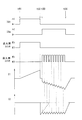
次に、図2を参照して点火装置1の正常時の動作を説明する。
なお、図2において、「IGt」は点火信号IGtの入力状態をハイ/ローで表すものであり、「IGw」は放電継続信号IGwの入力状態をハイ/ローで表すものである。また、「点火用スイッチ」、「投入用スイッチ」は、それぞれ、点火用スイッチング手段13、投入用スイッチング手段24のオンオフを表し、「I1」は1次電流(1次コイル5に流れる電流値)、「I2」は2次電流(2次コイル6に流れる電流値)を表す。
Next, the normal operation of the ignition device 1 will be described with reference to FIG.
In FIG. 2, “IGt” represents the input state of the ignition signal IGt as high / low, and “IGw” represents the input state of the discharge continuation signal IGw as high / low. “Ignition switch” and “turn-on switch” represent on / off of the ignition switching means 13 and the turn-on switching means 24, respectively, and “I1” is the primary current (current value flowing through the primary coil 5). , “I2” represents a secondary current (a current value flowing through the secondary coil 6).
点火信号IGtがローからハイへ切り替わると(時間t01参照。)、点火信号IGtがハイの期間において、点火用スイッチング手段13がオン状態を維持してプラスの1次電流が流れ、1次コイル5に磁気エネルギーが蓄えられる。また、昇圧用スイッチング手段20がオンオフを繰り返して昇圧動作を行い、昇圧された電気エネルギーがコンデンサ18に蓄えられる。
When the ignition signal IGt switches from low to high (see time t01), during the period when the ignition signal IGt is high, the ignition switching means 13 is maintained in an on state and a positive primary current flows, and the
やがて、点火信号IGtがハイからローへ切り替わると(時間t02参照。)、点火用スイッチング手段13がオフされ、1次コイル5の通電状態が遮断される。これにより、1次コイル5に蓄えられた磁気エネルギーが電気エネルギーに変換されて2次コイル6に高電圧が発生し、点火プラグ2において主点火が開始される。
点火プラグ2において主点火が開始された後、2次電流は略三角波形状で減衰する(I2の点線を参照。)。そして、2次電流が下限の閾値に到達する前に、放電継続信号IGwがローからハイへ切り替わる(時間t03参照。)。
Eventually, when the ignition signal IGt switches from high to low (see time t02), the ignition switching means 13 is turned off and the energized state of the
After the main ignition is started in the spark plug 2, the secondary current attenuates in a substantially triangular wave shape (see the dotted line I2). Then, the discharge continuation signal IGw switches from low to high before the secondary current reaches the lower limit threshold (see time t03).
放電継続信号IGwがローからハイへ切り替わると、投入用スイッチング手段24がオンオフ制御されて、コンデンサ18に蓄えられていた電気エネルギーが、1次コイル5のマイナス側に順次投入され、1次電流は、1次コイル5から車載バッテリ12のプラス電極に向かって流れる。より具体的には、投入用スイッチング手段24がオンされる毎に1次コイル5から車載バッテリ12のプラス電極に向かう1次電流が追加され、1次電流がマイナス側に増加していく(時間t03〜t04参照。)。
When the discharge continuation signal IGw switches from low to high, the on / off switching means 24 is on / off controlled, and the electric energy stored in the
すなわち、1次電流の追加により2次電流が上限(後記する制御上限H)に達すると、投入用スイッチング手段24がオフしてエネルギー投入が停止し、2次電流が徐々に低下していく。また、2次電流が下限(後記する制御下限L)に達すると、投入用スイッチング手段24がオンしてエネルギー投入が再開する。そして、1次電流が追加される毎に、主点火による2次電流と同方向の2次電流が2次コイル6に順次追加され、2次電流は上限下限の間に維持される。
以上により、投入用スイッチング手段24をオンオフ制御することで、2次電流が火花放電を維持可能な程度に継続して流れる。その結果、放電継続信号IGwのオン状態が続くと、継続火花放電が点火プラグ2において維持される。
That is, when the secondary current reaches the upper limit (control upper limit H, which will be described later) by adding the primary current, the input switching means 24 is turned off, energy input is stopped, and the secondary current gradually decreases. When the secondary current reaches the lower limit (control lower limit L, which will be described later), the input switching means 24 is turned on and energy input is resumed. Each time the primary current is added, a secondary current in the same direction as the secondary current caused by the main ignition is sequentially added to the
As described above, by controlling the on / off switching means 24, the secondary current continuously flows to such an extent that the spark discharge can be maintained. As a result, if the ON state of the discharge continuation signal IGw continues, continuous spark discharge is maintained in the spark plug 2.
次に、実施例1の特徴的な構成について説明する。
点火装置1の異常判定部11は、主に、継続火花放電中の2次電流が異常な数値を示すことにより、エンジン失火に至ったり、更なる故障に至ったりすることを防止するため、次のように2次電流に対する許容範囲を設定する。
Next, a characteristic configuration of the first embodiment will be described.
The
すなわち、許容範囲とは、エネルギー投入回路9の動作時の2次電流の検出値に対して設定されるものであり、許容範囲の上限の閾値は、電流検出回路29が設定する上限の閾値よりも絶対値として大きく、許容範囲の下限の閾値は、電流検出回路29が設定する下限の閾値よりも絶対値として小さい。
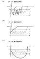
以下の説明では、電流検出回路29が設定する上限、下限の閾値をそれぞれ制御上限H、制御下限Lと呼び、異常判定部11が設定する上限、下限の閾値をそれぞれ許容上限HH、許容下限LLと呼ぶ(図3参照。)。
That is, the allowable range is set with respect to the detected value of the secondary current during the operation of the
In the following description, the upper and lower thresholds set by the
そして、異常判定部11は、エネルギー投入回路9の動作時に、2次電流の検出値が許容範囲を外れたか否かを判定し、2次電流の検出値が許容範囲を外れたと判定した場合に、2次電流の検出値が許容範囲を外れたことを示すダイアグ信号IGfをECU4に出力する。
なお、以下の説明では、2次電流の検出値が許容範囲を外れたか否かを判定する機能を、単に判定手段と呼ぶことがある。
Then, the
In the following description, the function of determining whether or not the detected value of the secondary current is outside the allowable range may be simply referred to as determination means.
ここで、異常判定部11は、放電継続信号IGwが入力されている間、2次電流の検出値の絶対値が許容上限HHよりも大きくならないか、または、2次電流の検出値の絶対値が許容下限LLよりも小さくならないかを監視する(つまり、図2および図3の時間t03が、異常判定部11による2次電流の検出値に対する監視を開始する時期に相当する。)。
Here, the
そして、異常判定部11は、例えば、2次電流の検出値が許容範囲を外れる単位時間当たりの回数(つまり、頻度)や、2次電流の検出値が許容範囲を外れる時間の長さに基づき、判定手段としての機能を果たす。
例えば、異常判定部11は、2次電流の検出値が所定の時間内に2回以上許容範囲を外れたときに、2次電流の検出値が許容範囲を外れたものと判定する。また、異常判定部11は、2次電流の検出値が所定の時間連続して許容範囲を外れたときに、2次電流の検出値が許容範囲を外れたものと判定する。
For example, the
For example, the
そして、ECU4は、例えば、2次電流の検出値が許容範囲を外れた気筒に対し、次のような処置をとることができる。すなわち、ECU4は、当該気筒に対して放電継続信号IGwの出力を停止し、当該気筒における火花放電を主点火のみに基づくものとする処置をとることができる。
For example, the
また、ECU4は、ダイアグ信号IGfの入力を受けた場合、各種公知の処理を実施して警告表示装置Aに所定の動作を行わせ、ユーザに異常を報知する。すなわち、警告表示装置Aは、異常判定部11により、2次電流の検出値が許容範囲を外れたものと判定されたときに、異常としてユーザに報知する報知手段として機能する。
When the
なお、継続火花放電は、制御上、リーンバーンのように気筒内のガス流速が高く、吹き消え発生の可能性がある運転状態において行われる。このため、吹き消え発生の可能性があるときに、判定手段を実行すると、故障が発生していないにも関わらず2次電流の検出値が許容下限LLよりも小さくなり、許容範囲を外れたものと判定してしまう虞がある。 Note that the continuous spark discharge is performed in an operating state where the gas flow rate in the cylinder is high and there is a possibility of blow-out, as in lean burn, for control purposes. For this reason, when there is a possibility that blowout will occur, if the determination means is executed, the detected value of the secondary current becomes smaller than the allowable lower limit LL even though no failure has occurred, and is outside the allowable range. There is a risk that it will be determined.
そこで、吹き消え発生の可能性が低いエンジン暖機後のアイドル運転時に、あえてエネルギー投入回路9を動作させて継続火花放電を発生させるようにした上で、判定手段を実行する。または、ガス流速が高いものの吹き消え発生の可能性がさほど高くない運転状態のときに、判定手段を実行する。これにより、吹き消えに伴う2次電流の検出値異常と、故障発生に伴う2次電流の検出値異常とを区別し、故障発生に伴う2次電流の検出値異常を確実に検知することができる。
Therefore, during idle operation after engine warm-up where the possibility of blow-off is low, the
また、2次電流の検出値が許容範囲を外れるパターンとして、以下のような第1〜第3の態様が考えられる。
まず、図3(a)に示すように、2次電流の経時変化を示す波形に関し、異常時の振幅が正常時の振幅に比べて大きくなり、波形の頂点近傍で2次電流の検出値が許容範囲を外れてしまう第1の態様が考えられる。この場合、異常判定部11は、2次電流の検出値が許容範囲を外れる頻度に基づき、2次電流の検出値が許容範囲を外れたものと判定する。なお、第1の態様は、投入用ドライバ回路25から投入用スイッチング手段24に与えられる制御信号が遅れている場合に発生するものと考えられる。
Moreover, the following 1st-3rd aspects can be considered as a pattern from which the detection value of a secondary current remove | deviates from an allowable range.
First, as shown in FIG. 3 (a), regarding the waveform indicating the temporal change of the secondary current, the amplitude at the time of abnormality is larger than the amplitude at the normal time, and the detected value of the secondary current is near the top of the waveform. A first mode that falls outside the allowable range is conceivable. In this case, the
次に、図3(b)に示すように、主点火に伴う三角波が発生した後、ゼロのまま推移する第2の態様が考えられる。この場合、異常判定部11は、2次電流の検出値が許容範囲を外れる時間の長さに基づき、2次電流の検出値が許容範囲を外れたものと判定する。なお、第2の態様は、投入用ドライバ回路25から投入用スイッチング手段24に与えられる制御信号がオフ側に固定した場合に発生するものと考えられる。
Next, as shown in FIG. 3B, a second mode in which the triangular wave associated with the main ignition is generated and then remains zero can be considered. In this case, the
さらに、図3(c)に示すように、主点火発生後に2次電流の検出値が絶対値を増やしながら制御上限Hを超え、さらに許容上限HHを超えた後、減少に転じ、絶対値を減らしながら許容上限HHを超え、さらに制御上限Hを超えてゼロに戻る第3の態様が考えられる。この場合、異常判定部11は、2次電流の検出値が許容範囲を外れる時間の長さに基づき、2次電流の検出値が許容範囲を外れたものと判定する。なお、第3の態様は、投入用ドライバ回路25から投入用スイッチング手段24に与えられる制御信号がオン側に固定した場合に発生するものと考えられる。
Further, as shown in FIG. 3 (c), after the main ignition occurs, the detected value of the secondary current exceeds the control upper limit H while increasing the absolute value, and further exceeds the allowable upper limit HH. A third mode may be considered in which the allowable upper limit HH is exceeded while decreasing and further exceeds the control upper limit H and returns to zero. In this case, the
〔実施例1の効果〕
実施例1の点火装置1によれば、異常判定部11は、エネルギー投入回路9の動作時の2次電流の検出値に対する許容範囲を設定するとともに、2次電流の検出値が許容範囲を外れたか否かを判定する。
これにより、2次電流の検出値が許容範囲を外れたことを検知することができる。このため、エネルギー投入回路9の動作時に2次電流の異常を判定して、ECU4に知らせることができる。
[Effect of Example 1]
According to the ignition device 1 of the first embodiment, the
Thereby, it can be detected that the detected value of the secondary current is out of the allowable range. For this reason, the abnormality of the secondary current can be determined during the operation of the
さらに、ECU4で各種公知の処理を実施することで、警告表示装置Aによりユーザに異常を報知することができる。この結果、例えば、ディーラー等への修理持ち込みを促して更なる故障を防止することができる。
Furthermore, the warning display device A can notify the user of the abnormality by performing various known processes in the
〔実施例2〕
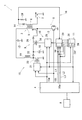
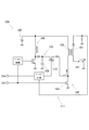
実施例2の点火装置1は、図4に示すように、2次電流の指令値を示す2次電流指令信号IGaの入力をECU4から受ける。そして、点火装置1は、電流検出回路29に2次電流指令回路30を設け、2次電流指令回路30により、2次電流指令信号IGaの入力を受ける。また、電流検出回路29は、2次電流指令回路30から出力された2次電流の指令値と2次電流の検出値とを比較した結果に応じてフィードバック信号を合成する。
[Example 2]
As shown in FIG. 4, the ignition device 1 of the second embodiment receives an input of a secondary current command signal IGa indicating a command value of the secondary current from the
ここで、2次電流指令信号IGaは、点火信号IGtおよび放電継続信号IGwを出力する信号線とは別の3本の信号線L1〜L3によりECU4から点火装置1に出力される。また、ECU4は、内燃機関の運転状態を示すエンジンパラメータを各種センサから取得するとともにエンジンパラメータに応じて2次電流の指令値を求め、2次電流指令信号IGaを合成して出力する。
Here, the secondary current command signal IGa is output from the
このとき、ECU4は、エンジンパラメータに応じて、予め設定された複数の数値から1つの数値を2次電流の指令値として選択する。また、ECU4は、それぞれの数値に対応した2次電流指令信号IGaの態様を信号線L1〜L3の電位(ハイ/ロー)の組合せにより設定している。
At this time, the
例えば、ECU4が2次電流の指令値として200mA、150mA、100mAの3つの数値を設定しているものとする(図5(b)参照。)。この場合、2次電流の指令値として200mAを選択した場合、2次電流指令信号IGaの態様は、例えば、信号線L1:ハイ、信号線L2:ロー、信号線L3:ローに設定され、150mAを選択した場合、信号線L1:ロー、信号線L2:ハイ、信号線L3:ローに設定され、100mAを選択した場合、信号線L1:ロー、信号線L2:ロー、信号線L3:ハイに設定されるものとする。
For example, it is assumed that the
また、2次電流指令回路30は、信号線L1〜L3のそれぞれの論理信号からノイズを除去する3つの波形成形部32と、2次電流指令信号IGaの態様に応じた電位を出力する指令値出力部33とを有する(図5(a)参照。)。ここで、指令値出力部33は、1つの抵抗R0と、4つの抵抗R1〜R4が互いに並列をなす並列部34とが直列をなし、抵抗R0と並列部34との接続部35における電位を指令値として出力する。
In addition, the secondary
すなわち、並列部34において並列に設けられた4つの枝路の内、抵抗R1〜R3が組み入れられた枝路には、それぞれスイッチング素子Tr1〜Tr3が組み入れられている。また、スイッチング素子Tr1〜Tr3は、それぞれ抵抗R1〜R3と直列に組み入れられている。また、スイッチング素子Tr1〜Tr3は、例えば、バイポーラランジスタである。そして、スイッチング素子Tr1〜Tr3のそれぞれのベースには信号線L1〜L3のハイ/ローが論理変換されずに入力され、スイッチング素子Tr1〜Tr3は、信号線L1〜L3のハイ/ローに応じてオンオフする。
That is, among the four branches provided in parallel in the
これにより、信号線L1〜L3のハイ/ローに応じて並列部34の合成抵抗が3つの数値の間で変わるので、接続部35における電位も、信号線L1〜L3のハイ/ローに応じて3つの数値の間で変化する。このため、2次電流指令回路30は、2次電流指令信号IGaの態様に応じて、2次電流の指令値を200mA、150mA、100mAの内から選択して出力することができる。
As a result, the combined resistance of the
そして、実施例2の点火装置1によれば、異常判定部11は、2次電流の指令値に応じて許容範囲を変更する。
すなわち、異常判定部11には、許容上限HH、許容下限LLをそれぞれ出力する許容上限指令回路38、許容下限指令回路39を有する(図4参照。)。また、許容上限指令回路38、許容下限指令回路39は、両方とも、2次電流指令回路30と同様の回路構成であり、信号線L1〜L3を通じて2次電流指令信号IGaの入力を受ける。
And according to the ignition device 1 of Example 2, the
That is, the
そして、許容上限指令回路38は、信号線L1〜L3のハイ/ローに応じて、許容上限HHを指令値200mA、150mA、100mAのそれぞれに対応する3つの数値の中から選択して出力する。同様に、許容下限指令回路39は、信号線L1〜L3のハイ/ローに応じて、許容下限LLを指令値200mA、150mA、100mAのそれぞれに対応する3つの数値の中から選択して出力する。
Then, the allowable upper
以上により、実施例2の点火装置1によれば、異常判定部11は、許容範囲を2次電流の指令値に応じて変更することができるので、指令値の変更に伴う誤判定を防止することができる。
As described above, according to the ignition device 1 of the second embodiment, the
〔変形例〕
上記の実施例では、2次電流の検出値が許容範囲を外れるパターンとして、上述の第1〜第3の態様を例示したが、2次電流の検出値が許容範囲を外れるパターンは、第1〜第3の態様に限定されず、他にも様々な態様が考えられるので、第1〜第3の態様以外の態様でも、点火装置1は、2次電流の検出値異常を検知することができる。
[Modification]
In the above embodiment, the first to third aspects described above are illustrated as patterns in which the detected value of the secondary current is outside the allowable range. However, the pattern in which the detected value of the secondary current is outside the allowable range is the first pattern. Since the present invention is not limited to the third mode and various other modes are possible, the ignition device 1 may detect an abnormality in the detected value of the secondary current in modes other than the first to third modes. it can.
上記の実施例2の2次電流指令回路は、3本の信号線L1〜L3により2次電流指令信号IGaの入力を受けて、3つの異なる数値の中から1つの数値を選択することで2次電流の指令値を把握するものであったが、2本または4本以上の信号線により2次電流指令信号IGaの入力を受けてもよく、4つ以上の異なる数値の中から1つの数値を選択することで2次電流の指令値を把握してもよい。さらに、1本の信号線により2次電流指令信号IGaの入力を受けてもよく、この場合、1本の信号線におけるハイ/ローにより、2次電流の指令値として2つの数値から一方の数値を選択することができる。 The secondary current command circuit of the second embodiment receives the input of the secondary current command signal IGa through the three signal lines L1 to L3, and selects one value from three different values. Although the command value of the secondary current was grasped, the secondary current command signal IGa may be received by two or four or more signal lines, and one numerical value among four or more different numerical values may be received. The command value of the secondary current may be grasped by selecting. Further, the secondary current command signal IGa may be input by one signal line. In this case, one of the numerical values from the two numerical values as the secondary current command value by the high / low in the single signal line. Can be selected.
上記の実施例では、ガソリンエンジンに本発明の点火装置1を用いる例を示したが、継続火花放電によって燃料(具体的には混合気)の着火性の向上を図ることができるため、エタノール燃料や混合燃料を用いるエンジンに適用してもよい。また、粗悪燃料が用いられる可能性のあるエンジンに用いても継続火花放電により着火性の向上を図ることができる。 In the above embodiment, an example in which the ignition device 1 of the present invention is used for a gasoline engine has been shown. However, since the ignition property of fuel (specifically, air-fuel mixture) can be improved by continuous spark discharge, ethanol fuel can be used. Or an engine using a mixed fuel. Even if it is used for an engine in which poor fuel may be used, the ignitability can be improved by continuous spark discharge.
上記の実施例では、希薄燃焼(リーンバーン)運転が可能なエンジンに本発明の点火装置1を用いる例を示したが、希薄燃焼とは異なる燃焼状態であっても継続火花放電によって着火性の向上を図ることができるため、希薄燃焼可能なエンジンへの適用に限定するものではなく、希薄燃焼を行わないエンジンに用いてもよい。 In the above-described embodiment, an example in which the ignition device 1 of the present invention is used for an engine capable of lean burn operation has been shown. However, even in a combustion state different from lean combustion, ignitability is caused by continuous spark discharge. Since improvement can be achieved, the present invention is not limited to application to an engine capable of lean combustion, and may be used for an engine that does not perform lean combustion.
上記の実施例では、燃焼室に直接燃料を噴射する直噴式エンジンに本発明の点火装置1を用いる例を示したが、吸気バルブの吸気上流側(吸気ポート内)に燃料を噴射するポート噴射式のエンジンに用いてもよい。 In the above embodiment, an example in which the ignition device 1 of the present invention is used in a direct injection engine that directly injects fuel into the combustion chamber has been described. However, port injection that injects fuel to the intake upstream side (inside the intake port) of the intake valve. It may be used for a formula engine.
上記の実施例では、混合気の旋回流(タンブル流やスワール流等)を気筒内にて積極的に生じさせるエンジンに本発明の点火装置1を用いる例を開示したが、旋回流コントロール手段(タンブル流コントロールバルブやスワール流コントロールバルブ等)を有しないエンジンに用いてもよい。 In the above-described embodiment, an example in which the ignition device 1 of the present invention is used for an engine that positively generates a swirl flow (such as a tumble flow or a swirl flow) of an air-fuel mixture in a cylinder has been disclosed. You may use for the engine which does not have a tumble flow control valve, a swirl flow control valve, etc.).
1 点火装置 2 点火プラグ 3 点火コイル 5 1次コイル 6 2次コイル 8 主点火回路 9 エネルギー投入回路 28 2次電流検出抵抗(2次電流検出手段) 29 電流検出回路 H 制御上限 L 制御下限 HH 許容上限 LL 許容下限
DESCRIPTION OF SYMBOLS 1 Ignition device 2
Claims (3)
この主点火回路(8)の動作によって開始した火花放電中に、前記1次コイル(5)の通電制御を行って、前記点火コイル(3)の2次コイル(6)に同一方向の2次電流を継続して流し、前記主点火回路(8)の動作によって開始した火花放電を継続させるエネルギー投入回路(9)と、
2次電流を検出する2次電流検出手段(28)と、
前記エネルギー投入回路(9)の動作時の2次電流の検出値に対し、絶対値としての上限、下限それぞれの閾値である制御上限(H)、制御下限(L)を設定するとともに、これら制御上限(H)、制御下限(L)と前記検出値との比較に基づき、前記エネルギー投入回路(9)による通電制御を行うためのフィードバック信号を出力する電流検出回路(29)と、
前記エネルギー投入回路(9)の動作時の2次電流の検出値に対し、前記制御上限(H)よりも絶対値として大きい許容上限(HH)、および、前記制御下限(L)よりも絶対値として小さい許容下限(LL)により画される許容範囲を設定するとともに、2次電流の検出値が前記許容範囲を外れたか否かを判定する異常判定部(11)とを備える内燃機関用の点火装置(1)。 A main ignition circuit (8) for controlling the energization of the primary coil (5) of the ignition coil (3) to cause a spark discharge in the spark plug (2);
During the spark discharge started by the operation of the main ignition circuit (8), the energization control of the primary coil (5) is performed, and the secondary coil (6) of the ignition coil (3) is subjected to the secondary in the same direction. An energy input circuit (9) for continuously supplying a current and continuing the spark discharge started by the operation of the main ignition circuit (8);
Secondary current detection means (28) for detecting the secondary current;
A control upper limit (H) and a control lower limit (L), which are upper and lower limits as absolute values, are set for the detected value of the secondary current during operation of the energy input circuit (9), and these controls are performed. A current detection circuit (29) for outputting a feedback signal for performing energization control by the energy input circuit (9) based on comparison between the upper limit (H) and the control lower limit (L) and the detected value;
The against the detected value of the secondary current during the operation of the energy input circuit (9), a large allowable upper absolute value than the control upper (H) (HH), and the lower control limit (L) from the absolute An internal combustion engine is provided with an abnormality determining unit (11) that sets an allowable range defined by a small allowable lower limit (LL) as a value and determines whether or not a detected value of a secondary current is out of the allowable range. Ignition device (1).
前記異常判定部(11)は、前記許容範囲を2次電流の指令値に応じて変更することを特徴とする内燃機関用の点火装置(1)。 Ignition device (1) according to claim 1,
The internal combustion engine ignition device (1), wherein the abnormality determination unit (11) changes the allowable range in accordance with a command value of a secondary current.
前記異常判定部(11)により、2次電流の検出値が前記許容範囲を外れたものと判定されたときに、異常としてユーザに報知する報知手段を備える点火装置(1)。 The ignition device (1) according to claim 1 or 2,
An ignition device (1) provided with an informing means for informing the user of an abnormality when the abnormality determining unit (11) determines that the detected value of the secondary current is out of the allowable range.
Priority Applications (3)
| Application Number | Priority Date | Filing Date | Title |
|---|---|---|---|
| JP2014080626A JP6375673B2 (en) | 2014-04-10 | 2014-04-10 | Ignition device |
| US15/302,072 US10082125B2 (en) | 2014-04-10 | 2015-04-09 | Control apparatus and ignition apparatus |
| PCT/JP2015/061173 WO2015156371A1 (en) | 2014-04-10 | 2015-04-09 | Control device and ignition device |
Applications Claiming Priority (1)
| Application Number | Priority Date | Filing Date | Title |
|---|---|---|---|
| JP2014080626A JP6375673B2 (en) | 2014-04-10 | 2014-04-10 | Ignition device |
Publications (2)
| Publication Number | Publication Date |
|---|---|
| JP2015200251A JP2015200251A (en) | 2015-11-12 |
| JP6375673B2 true JP6375673B2 (en) | 2018-08-22 |
Family
ID=54551739
Family Applications (1)
| Application Number | Title | Priority Date | Filing Date |
|---|---|---|---|
| JP2014080626A Expired - Fee Related JP6375673B2 (en) | 2014-04-10 | 2014-04-10 | Ignition device |
Country Status (1)
| Country | Link |
|---|---|
| JP (1) | JP6375673B2 (en) |
Families Citing this family (1)
| Publication number | Priority date | Publication date | Assignee | Title |
|---|---|---|---|---|
| JP7408453B2 (en) * | 2020-03-25 | 2024-01-05 | 日立Astemo阪神株式会社 | Ignition system for internal combustion engines |
Family Cites Families (3)
| Publication number | Priority date | Publication date | Assignee | Title |
|---|---|---|---|---|
| JP2657941B2 (en) * | 1994-02-18 | 1997-09-30 | 阪神エレクトリック株式会社 | Overlap discharge type ignition device for internal combustion engine |
| JP2000170632A (en) * | 1998-12-07 | 2000-06-20 | Ngk Spark Plug Co Ltd | Ignition device |
| JP2003028037A (en) * | 2001-07-18 | 2003-01-29 | Denso Corp | Ignition device for internal combustion engine |
-
2014
- 2014-04-10 JP JP2014080626A patent/JP6375673B2/en not_active Expired - Fee Related
Also Published As
| Publication number | Publication date |
|---|---|
| JP2015200251A (en) | 2015-11-12 |
Similar Documents
| Publication | Publication Date | Title |
|---|---|---|
| JP6269271B2 (en) | Ignition device for internal combustion engine | |
| WO2015156371A1 (en) | Control device and ignition device | |
| JP6489929B2 (en) | Ignition device | |
| JP6372140B2 (en) | Ignition device | |
| WO2015156341A1 (en) | Ignition device and ignition system | |
| JP6610073B2 (en) | Ignition device | |
| JP6337584B2 (en) | Ignition device | |
| JP6273988B2 (en) | Ignition device for internal combustion engine | |
| JP6549901B2 (en) | Igniter | |
| JP6609111B2 (en) | Ignition device | |
| JP6375673B2 (en) | Ignition device | |
| JP6708188B2 (en) | Ignition device | |
| US9957944B2 (en) | Ignition apparatus for internal combustion engine | |
| JPWO2019198119A1 (en) | Ignition system for internal combustion engine | |
| JP6264166B2 (en) | Ignition device failure diagnosis device and ignition device failure diagnosis method | |
| JP6627644B2 (en) | Ignition control device | |
| JP6398272B2 (en) | Ignition device | |
| JP6622513B2 (en) | Ignition device | |
| JP6291984B2 (en) | Ignition device for internal combustion engine | |
| JPWO2019130462A1 (en) | Ignition system for internal combustion engine | |
| JP6265016B2 (en) | Ignition device | |
| JP6331618B2 (en) | Ignition device for internal combustion engine |
Legal Events
| Date | Code | Title | Description |
|---|---|---|---|
| A621 | Written request for application examination |
Free format text: JAPANESE INTERMEDIATE CODE: A621 Effective date: 20170308 |
|
| A131 | Notification of reasons for refusal |
Free format text: JAPANESE INTERMEDIATE CODE: A131 Effective date: 20180213 |
|
| A521 | Request for written amendment filed |
Free format text: JAPANESE INTERMEDIATE CODE: A523 Effective date: 20180305 |
|
| TRDD | Decision of grant or rejection written | ||
| A01 | Written decision to grant a patent or to grant a registration (utility model) |
Free format text: JAPANESE INTERMEDIATE CODE: A01 Effective date: 20180626 |
|
| A61 | First payment of annual fees (during grant procedure) |
Free format text: JAPANESE INTERMEDIATE CODE: A61 Effective date: 20180709 |
|
| R151 | Written notification of patent or utility model registration |
Ref document number: 6375673 Country of ref document: JP Free format text: JAPANESE INTERMEDIATE CODE: R151 |
|
| R250 | Receipt of annual fees |
Free format text: JAPANESE INTERMEDIATE CODE: R250 |
|
| R250 | Receipt of annual fees |
Free format text: JAPANESE INTERMEDIATE CODE: R250 |
|
| R250 | Receipt of annual fees |
Free format text: JAPANESE INTERMEDIATE CODE: R250 |
|
| LAPS | Cancellation because of no payment of annual fees |