JP6373002B2 - Recording apparatus and control method thereof - Google Patents
Recording apparatus and control method thereof Download PDFInfo
- Publication number
- JP6373002B2 JP6373002B2 JP2013268610A JP2013268610A JP6373002B2 JP 6373002 B2 JP6373002 B2 JP 6373002B2 JP 2013268610 A JP2013268610 A JP 2013268610A JP 2013268610 A JP2013268610 A JP 2013268610A JP 6373002 B2 JP6373002 B2 JP 6373002B2
- Authority
- JP
- Japan
- Prior art keywords
- moving image
- recording medium
- recording
- image data
- data
- Prior art date
- Legal status (The legal status is an assumption and is not a legal conclusion. Google has not performed a legal analysis and makes no representation as to the accuracy of the status listed.)
- Active
Links
Images


Description
本発明は記録装置およびその制御方法に関する。 The present invention relates to a recording apparatus and a control method thereof.
近年、デジタルカメラおよびデジタルビデオカメラの記録媒体として、NAND型フラッシュメモリ(登録商標)が主流となっている。NAND型フラッシュメモリを用いた内蔵型メモリやメモリカードは、書き込みサイズが数メガバイト(MB)と大きく、かつ書き込み開始アドレスがブロック境界に合致している場合は、転送レートが非常に高速である。一方、メモリへの書き込みサイズが1セクタ(512バイト)単位前後と小さく、かつ書き込みアドレスがランダムな場合は転送レートが非常に遅くなるという特性を持っている。また、メモリへの一回の書き込みサイズが大きい場合は転送レートが速く、小さい場合は転送レートが遅くなる傾向もある。このように一般的なメモリカードは、書き込みサイズによって転送レートが変動する。動画データをメモリカードに記録するためには、メモリカードへの転送レートが安定している必要があるが、カードによっては転送レートが不足して録画が停止してしまったりするおそれがあった。 In recent years, NAND flash memory (registered trademark) has become mainstream as a recording medium for digital cameras and digital video cameras. A built-in memory or memory card using a NAND flash memory has a very high transfer rate when the write size is as large as several megabytes (MB) and the write start address matches the block boundary. On the other hand, when the write size to the memory is as small as about 1 sector (512 bytes) unit and the write address is random, the transfer rate is very slow. Also, the transfer rate tends to be fast when the write size to the memory is large, and the transfer rate tends to be slow when it is small. Thus, the transfer rate of a general memory card varies depending on the writing size. In order to record moving image data on a memory card, the transfer rate to the memory card needs to be stable, but depending on the card, the transfer rate may be insufficient and recording may stop.
そこで、従来、あらかじめ定められた固定のアクセスサイズでアクセスした場合のアクセス速度、およびファイルシステム更新の書き込み速度を保証することが提案されている(例えば、特許文献1参照)。 Therefore, conventionally, it has been proposed to guarantee the access speed when accessing with a predetermined fixed access size and the writing speed of file system update (see, for example, Patent Document 1).
しかしながら、書き込み速度を保証するアクセスサイズは、各カードに対して一つのみ規定されているため、以下の問題があった。即ち、動画データを記録する場合、カードへの記録レートと動画データのデータレートが違うため、動画データを一旦メモリに蓄積しておき、アクセスサイズと同等のデータ量が蓄積されると、記録媒体への記録が実行される。このとき、カードへの動画データの書き込み周期は、動画データのデータレートによって異なる。 However, since only one access size that guarantees the writing speed is defined for each card, there are the following problems. That is, when recording moving image data, since the recording rate to the card and the data rate of the moving image data are different, the moving image data is once stored in the memory, and when the data amount equivalent to the access size is stored, the recording medium Recording to is performed. At this time, the cycle of writing the moving image data to the card differs depending on the data rate of the moving image data.
例えば、アクセスサイズが4MBと規定されており、記録する動画データのデータレートが10MB/秒(80Mbps)の場合、4MB/(10MB/秒)=0.4秒周期で書き込みが実行される。また、動画データのデータレートが1MB/秒(8Mbps)の場合は4秒周期で書き込みが実行される。 For example, when the access size is defined as 4 MB and the data rate of moving image data to be recorded is 10 MB / second (80 Mbps), writing is executed at a cycle of 4 MB / (10 MB / second) = 0.4 seconds. Further, when the data rate of the moving image data is 1 MB / second (8 Mbps), writing is executed at a cycle of 4 seconds.
ところが、このようにデータレートが異なる複数の動画データを同時に一つのメモリカードに記録しようとした場合は、前述のようにデータ毎に書き込みの周期が異なるため、書き込み制御が難しくなる。 However, when a plurality of moving image data having different data rates are simultaneously recorded on one memory card as described above, the writing cycle is different for each data as described above, so that writing control becomes difficult.
また、データレートが異なる複数の動画データがメモリカードに同じタイミングで記録されないと、バッテリーが切れるなど、記録の強制終了が発生した場合に、動画データの記録時間が一致しないなどの不都合が生じる。 In addition, if a plurality of moving image data having different data rates are not recorded on the memory card at the same timing, the recording time of moving image data does not match when the recording is forcibly terminated, for example, the battery runs out.
また、特許文献1では、メモリカードにおけるアクセスサイズ毎の空き領域の割合に応じて記録速度を保証しているため、記録側のシステムにおいては、カードへの書き込みアドレスが不連続になり、システム側の負荷になるという問題もある。
Further, in
本発明は以上の点を鑑みてなされたものであり、適切なタイミングで動画データを記録媒体に書き込むことができる記録装置及びその制御方法の提供を目的とする。 The present invention has been made in view of the above points, and an object of the present invention is to provide a recording apparatus capable of writing moving image data to a recording medium at an appropriate timing and a control method therefor.
以上の目的を達成するため、本発明の記録装置は、動画データを生成する処理手段と、記録媒体に対して書き込みコマンドを出力することにより、前記動画データを前記記録媒体に書き込む記録手段と、複数の所定のデータ量から、1回の前記書き込みコマンドによって前記記録媒体に書き込まれる動画データのデータ量を設定し、前記設定したデータ量の動画データを1回の前記書き込みコマンドにより前記記録媒体に書き込むように前記記録手段を制御する制御手段とを有することを特徴とする。 In order to achieve the above object, the recording apparatus of the present invention includes a processing unit that generates moving image data, a recording unit that writes the moving image data to the recording medium by outputting a write command to the recording medium, A data amount of moving image data written to the recording medium by one write command is set from a plurality of predetermined data amounts, and the moving image data having the set data amount is set on the recording medium by one write command. And a control means for controlling the recording means to write.
本発明の記録装置によれば、適切なタイミングで動画データを記録媒体に書き込むことができる記録装置及びその制御方法を提供できる。 According to the recording apparatus of the present invention, it is possible to provide a recording apparatus capable of writing moving image data to a recording medium at an appropriate timing and a control method therefor.
以下、図面を参照しながら本発明の例示的な実施形態を説明する。
●(第1の実施形態)
本発明に係る記録装置は、動画データを記録可能な任意の記録装置であってよい。ここでは一例としてのデジタルビデオカメラ100について、図面を用いて説明する。図1は、本実施形態のデジタルビデオカメラ100の機能構成例を示すブロック図であり、撮影レンズ101に入射した光束は絞り102によって光量が所定量に制限された後、撮像素子103上に被写体像を結像させる。撮像素子103がアナログ信号に変換した被写体像は、A/Dコンバータ104でデジタル化され、画像処理回路105でガンマ補正やホワイトバランス補正、ノイズリダクション処理等が行われた後、データバス107を介してメモリ114に記憶される。本実施形態で撮像素子103は、1画面(フレーム)が横3840画素×縦2160画素で、30フレーム毎秒の動画データを出力する。画像サイズ変換回路108は、メモリ114に記憶された動画データの各画面の画素数を、液晶パネル110に表示される画像の画素数、或いは、記録される動画の画素数となるように変換し、メモリ114に記憶する。
Hereinafter, exemplary embodiments of the present invention will be described with reference to the drawings.
● (first embodiment)
The recording device according to the present invention may be any recording device capable of recording moving image data. Here, a
符号化回路109は、メモリ114に記憶された記録用の動画データを読み出し、H.264等の公知の符号化処理を施して圧縮し、メモリ114に記憶する。液晶パネル110は、画像や各種情報を表示する表示部である。液晶ドライバ111は、メモリ114に格納されている表示用の画像データを液晶表示信号に変換して液晶パネル110に供給する。こうして、メモリ114に書き込まれた表示用の画像データは液晶ドライバ111を介して液晶パネル110により表示される。
The
ホストコントローラ112は、制御回路116からの指示に基づいて、記録媒体であるメモリカード113に対してコマンド信号を送信し、メモリ114に記憶された動画データを読み出してメモリカード113に書き込む。また、ホストコントローラ112は、メモリカード113からデータを読み出し、メモリ114に記憶する。メモリカード113は、カメラ本体に対して着脱が可能な、NAND型フラッシュメモリおよびフラッシュコントローラで構成されているメモリカードである。メモリカード113に記憶された動画データは、exFAT(Extended File Allocation Table)ファイルシステムに従って管理手段としての制御回路116がファイルとして管理する。
Based on an instruction from the
メモリ114はDRAMなどの揮発メモリで構成され、符号化回路109で生成される符号化動画データを一旦記憶し、メモリカード113の記録速度との調停を行うためのバッファとしてのメモリ空間を提供する。またメモリ114は、撮影された動画データの画面サイズを変換するための画像サイズ変換回路108の作業メモリ空間を提供するとともに、前述の通り、液晶パネル110に表示される画像を記憶する空間も提供する。操作回路115は、電源スイッチや記録開始、停止を指示するためのボタン等、ユーザが操作するための各種の操作キーを備える。操作回路115は、各種設定項目の設定キーを含む。
The
ROM117は、電気的に消去および書き込みが可能な不揮発メモリであって、制御回路(CPU)116で動作するプログラム等が格納される。ここでいうプログラムとは、本実施形態にて後述する各種シーケンスを実行するためのプログラムのことであり、後述する本実施形態の各処理を実現する。また、制御回路116は液晶ドライバ111等を制御することにより表示制御も行う。記録条件設定回路118は、動画データを記録するための各種の条件を設定する。
The
図2は、記録条件設定回路118の構成例を示すブロック図である。記録形式設定回路201は、操作回路115からの入力を受けた制御回路116からの指示により、一つの動画を記録するか、二つの動画を同時に記録するかを設定する。画像サイズ設定回路202は、操作回路115からの入力を受けた制御回路116からの指示により、記録される動画の画面サイズ(記録される動画データの1画面あたりの縦、横それぞれの画素数)を設定する。このとき、二つの動画を同時に記録する場合には、各動画についての画面サイズを設定する。データレート設定回路203は、操作回路115からの入力を受けた制御回路116からの指示により、記録される動画データのデータレートを設定する。このとき、二つの動画を同時に記録する場合には、各動画についてのデータレートを設定する。ユニットサイズ設定回路204は、設定された動画データのデータレートから、記録する時に用いるユニットサイズを設定する。このとき、二つの動画を同時に記録する場合には、各動画についてのユニットサイズを設定する。
FIG. 2 is a block diagram illustrating a configuration example of the recording
ファイルシステム更新設定回路205は、設定された動画データのデータレートおよびユニットサイズに応じて、ファイルシステム更新の頻度を設定する。このとき、二つの動画を同時に記録する場合には、各動画についてのファイルシステム更新の頻度を設定する。バッファ領域設定回路206は、設定されているユニットサイズから、未記録の動画データを記憶するためのバッファ領域として必要な領域をメモリ114内に設定する。このとき、二つの動画を同時に記録する場合には、各動画についてのバッファ領域を設定する。
The file system update setting
なお、図1、図2においては、記録条件設定回路118を制御回路116とは別の機能ブロックとして記載したが、記録条件設定回路118の一部、或いは、全ての機能ブロックが制御回路116により実現される様にしてもよい。
In FIG. 1 and FIG. 2, the recording
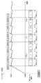
図3は、メモリカード113に対する動画データの書き込み及びFATの更新処理を示す図である。図3(a)において、Data Writeで示す部分は、ホストコントローラ112から発行される1回のWriteコマンドによるデータの書き込みが行われる期間である。1回の書き込みコマンドにより書き込まれるデータ量はN(MB)と規定されている。また、FAT Updateで示す部分は、FATファイルシステムの記述ルールに則り、メモリカード113に記録されたデータをファイルとして管理するための管理情報を記録するための期間を示す。FAT Updateの内容は、ファイルエントリ書き込み(1セクタ)→アロケーションビットマップ書き込み(1セクタ)→FAT書き込み(1セクタ)を含んでいる。図3に示すとおり、1回の書き込みコマンドによりN(MB)のデータの書き込みを開始した後、管理情報の書き込みが完了し、ファイルシステム更新が完了するまでに要する時間がTuwである。
FIG. 3 is a diagram showing video data writing and FAT update processing to the
このように、1回の書き込みコマンドにより書き込まれるデータ量(ユニットサイズ)、データの書き込みとファイルシステムの更新に要する時間Tuwを含む、メモリカードへのアクセス条件の定義を以下、性能定義ユニットと称する。即ち、メモリカード113に対し、1回の書き込みコマンドにより書き込まれる、複数の所定のデータ量と、対応した書き込み速度、書き込みの実行時間を含むアクセス条件が、性能定義ユニットとして定義されている。
In this manner, the definition of the access condition to the memory card including the amount of data (unit size) written by one write command and the time Tuw required for writing data and updating the file system is hereinafter referred to as a performance definition unit. . That is, an access condition including a plurality of predetermined data amounts, corresponding write speeds, and write execution times written to the
また、性能定義ユニットにより定義されたアクセス条件に従ってデータの書き込みを行った場合に、メモリカードの性能として、Tuwで示す時間内に動作が終了することが保証される。また、性能定義ユニットに定義されたアクセス条件によるデータの書き込み速度は、ユニットサイズ/Tuwで算出することができる。 In addition, when data is written according to the access conditions defined by the performance definition unit, the performance of the memory card is guaranteed to be completed within the time indicated by Tuw. Further, the data writing speed according to the access conditions defined in the performance definition unit can be calculated by unit size / Tuw.
一例として、ユニットサイズ=4MB、Tuw=100msecの性能定義ユニットの例を図3(b)および図3(c)に示す。図3(b)に示すMediaAと図3(c)に示すMediaBとでは、同じ100msecの動作期間に対してデータ記録の動作時間とファイルシステム更新の動作時間の内訳が異なっている。しかし、どちらも4MB/100msec=40MB/secの性能が定義される。すなわち、データの書き込み期間とファイルシステムの更新期間の内訳はどのような比率でもよい。 As an example, FIG. 3B and FIG. 3C show examples of performance definition units with a unit size = 4 MB and Tuw = 100 msec. In Media A shown in FIG. 3B and Media B shown in FIG. 3C, the breakdown of the data recording operation time and the file system update operation time is different for the same 100 msec operation period. However, in both cases, a performance of 4 MB / 100 msec = 40 MB / sec is defined. That is, the ratio between the data writing period and the file system update period may be any ratio.
図4は、本実施形態のメモリカード113で定義されている四つの性能定義ユニットによるアクセス条件を示す図である。性能定義ユニット1によるアクセス条件は、ユニットサイズ=16MB、Tuw=320msecであり、書き込み速度として50MB/secの性能を持つ。性能定義ユニット2によるアクセス条件は、ユニットサイズ=8MB、Tuw=200msecであり、書き込み速度として40MB/secの性能を持つ。性能定義ユニット3によるアクセス条件は、ユニットサイズ=4MB、Tuw=133msecであり、書き込み速度として30MB/secの性能を持つ。性能定義ユニット4によるアクセス条件は、ユニットサイズ=2MB、Tuw=100msecであり、書き込み速度として20MB/secの性能を持つ。
FIG. 4 is a diagram showing access conditions by four performance definition units defined in the
本実施形態では、これら四つの性能定義ユニットによるアクセス条件、並びに、書き込み性能に関する情報が、ROM117に記憶されているものとする。そして、制御回路116が、ROM117から各性能定義ユニットによるアクセス条件と書き込み性能を読み出す構成とする。しかしながら、メモリカード113に性能定義ユニットによるアクセス条件と書き込み性能の情報を記憶しておく構成としてもよい。この場合、制御回路116は、メモリカード113がカメラに装着された後、メモリカード113から性能定義ユニットによるアクセス条件と書き込み性能の情報を読み出す。
In the present embodiment, it is assumed that the
次に、本実施形態のデジタルカメラによる、動画記録時の動作を説明する。本実施形態では、ユーザが操作回路115を操作することにより、メモリカード113に記録する動画データの画面サイズ、及びデータレートを設定することができる。更に、本実施形態では、メモリカード113に対して二つの動画データを同時に記録することが可能である。ユーザは、二つの動画を同時に記録するか、或いは、一つの動画を記録するかを設定することができる。また、二つの動画を同時に記録する場合、ユーザは、各動画について、動画データの画面サイズ、及びデータレートを設定することができる。
Next, the operation at the time of moving image recording by the digital camera of this embodiment will be described. In the present embodiment, the user can set the screen size and data rate of moving image data to be recorded on the
本実施形態では、画面サイズとして、横3840画素×縦2160画素、横1920画素×縦1080画素、横640画素×縦480画素、の三つのモードの何れかを設定可能である。また、ユーザは、一つの動画を記録する場合、動画データのデータレートとして、高画質の動画データである36MB/秒と標準画質の動画データである18MB/秒の何れかを設定可能である。また、二つの動画データを同時に記録する場合、高画質の動画データである24MB/秒と、標準画質の動画データである12MB/秒の何れかを設定可能である。 In the present embodiment, as the screen size, any one of three modes of horizontal 3840 pixels × vertical 2160 pixels, horizontal 1920 pixels × vertical 1080 pixels, and horizontal 640 pixels × vertical 480 pixels can be set. Further, when recording one moving image, the user can set either 36 MB / second, which is high-quality moving image data, or 18 MB / second, which is standard-definition moving image data, as the data rate of the moving image data. When two moving image data are recorded simultaneously, either 24 MB / second, which is high-quality moving image data, or 12 MB / second, which is standard-definition moving image data, can be set.
図5(a)は、このようにユーザにより、記録する動画データが設定された時に実行される処理を示している。なお、図5(a)の処理は、制御回路116が各部を制御することにより実行される。
FIG. 5A shows processing executed when the moving image data to be recorded is set by the user as described above. 5A is executed by the
ユーザにより、記録される動画の画面サイズ、データレート及び記録形式が設定されると図5の処理が開始される。制御回路116は、設定された記録形式により、一つの動画を記録するか、或いは、二つの動画を同時に記録するかを判別する(S501)。一つの動画を記録する設定の場合、制御回路116は、ユーザの設定に基づいて、画像サイズ設定回路202に画面サイズを設定し、データレート設定回路203に動画のデータレートを設定する(S502)。
When the user sets the screen size, data rate, and recording format of the moving image to be recorded, the processing in FIG. 5 is started. The
次に、ユニットサイズ設定回路204は、設定された記録形式と動画のデータレートに基づき、ユニットサイズを設定する(S503)。具体的には、設定された動画のデータレートを上回る書き込み速度を持つ性能定義ユニットによるユニットサイズが設定される。例えば、ユーザにより高画質の動画データの記録が設定された場合、動画データレートが36MB/秒となる。そのため、図4に示す性能定義ユニットのうち、これを上回る書き込み速度を持つ性能定義ユニット2によるユニットサイズ8MBが設定される。
Next, the unit
さらに、制御回路116は、ファイルシステム更新設定回路205にファイルシステム更新の頻度を設定する(S504)。本実施形態では、一つのユニットサイズのデータの書き込みの度に実行されるよう設定する。次に、バッファ領域設定回路206は、設定されたユニットサイズから、記録時に必要となるバッファ領域のサイズを設定する。そして、設定したサイズの領域を、動画データのためのバッファメモリ領域としてメモリ114内に確保する(S505)。例えば、ユニットサイズ(Uz)が8MBに設定された場合、バッファ領域としては8MBより大きいサイズが確保される。また、メモリカード113に対する書き込みタイミングを決めるために用いられる、バッファメモリ領域のデータ蓄積量の閾値Tとして、ユニットサイズを設定する。
Further, the
一方、記録形式として同時記録が設定されていた場合の処理については後述する(S506)。以上の処理が終了したあと、記録待機状態となり、ユーザによる撮影開始指示を待つ状態となる。 On the other hand, the process when simultaneous recording is set as the recording format will be described later (S506). After the above processing is completed, the recording standby state is entered, and the user is in a state of waiting for an imaging start instruction.
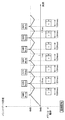
次に、一つの動画データを記録する際の処理を説明する。図5(b)は、記録形式として、一つの動画データを記録する設定の場合の記録処理を示すフローチャートである。また、図6は、記録開始後の、バッファ領域に記憶された動画データとメモリカード113に書き込まれるデータ及びファイルシステムの更新動作を示す図である。なお、図6は、8MBのバッファサイズに対応した、図4の性能定義ユニット2が選択された場合の様子を示している。
Next, a process when recording one moving image data will be described. FIG. 5B is a flowchart showing a recording process in the case of setting to record one moving image data as a recording format. FIG. 6 is a diagram showing the moving image data stored in the buffer area, the data written to the
記録待機状態において、ユーザが操作回路115を操作して記録開始を指示すると、撮像素子103からの動画データが画像処理回路105で処理され、フレームメモリ106に記憶される。画像サイズ変換回路108は、フレームメモリ106に記憶された動画データの各画面のサイズを、画像サイズ設定回路202で設定された画像サイズになるように変換し、メモリ114に記憶する。符号化回路109は、メモリ114に記憶された動画データを読み出して符号化し、バッファ領域設定回路206で設定されたメモリ114上のバッファ領域に記憶していく。このとき、符号化回路109は、符号化された動画データのデータレートが、設定されたデータレートにより決められた上限のレートを超えないように符号化する(S511)。
In the recording standby state, when the user operates the
次に、制御回路116は、バッファ領域に蓄積された、未記録の動画データのデータ量が、閾値Tに達したか否かを判別する(S512)。バッファ領域に蓄積された動画データのデータ量が閾値Tに達した場合、制御回路116は、ホストコントローラ112に対して、ユニットサイズUz分のデータ、ここでは8MBのデータを書き込むように指示する。ホストコントローラ112は、メモリカード113に対して書き込みコマンドを発行し、メモリ114上のバッファ領域から、ユニットサイズ分の動画データをメモリカードへ書き込む(S513)。この書き込み処理は、図6のメモリカード動作におけるaの期間で示されている。
Next, the
ファイルシステム更新設定回路205には、ユニットサイズUz毎の更新タイミングが設定されている。そのため、制御回路116は、ユニットサイズ分のデータの書き込みに続いて、ファイルシステムの更新を実行するように、ホストコントローラ112に指示する(S514)。このファイルシステム更新動作は、図6のメモリカード動作におけるbで示した期間に行われる。一つのユニットサイズ分の動画データの書き込みおよびファイルシステム更新は、性能定義ユニット2により200msec以内に完了することが保証されている。また、性能定義ユニット2による書き込み性能は40MB/秒である。一方、動画データのデータレートは36MB/秒であるので、図6において、メモリカードへのデータの書き込み中、バッファ領域に蓄積されたデータ量が4MB/秒の速度で減少する。ファイルシステムの更新が完了すると、制御回路116は、記録停止の指示の有無を判別し(S515)、記録停止の指示が無い場合はS512の処理に戻る。
In the file system
このように、メモリカード113への書き込み処理において、図6に示すように、バッファ領域に蓄積されるデータ量は8MBを超えることはなく、バッファがオーバーフローすることが無い。そのため、動画データの記録が停止することが無い。
Thus, in the writing process to the
ユーザにより記録停止が指示された場合、制御回路116はS515でそれを検出し、符号化回路109による動画データの符号化を停止するとともに、メモリ114のバッファ領域に対する符号化データの蓄積を停止する(S516)。そして、制御回路116は、ホストコントローラ112に対し、メモリ114のバッファ領域に残っている動画データの書き込み動作を行い(S517)、ファイルシステム更新を行った後(S518)、記録動作を終了する。なお、S517における書き込みでは、書き込みコマンドにより書き込まれるデータのサイズがユニットサイズとは一致しないので、書き込み速度が低下することが考えられる。しかし、記録停止の指示の後の書き込み動作となるため、書き込み性能が低下しても問題はない。
When recording stop is instructed by the user, the
図7は、ユーザにより動画データのデータレートとして18MB/秒が設定された場合の、バッファ領域に記憶された動画データとメモリカード113に書き込まれるデータ及びファイルシステムの更新動作を示す図である。動画データのデータレートが18MB/秒の場合、性能定義ユニット1−4の何れを選択した場合でも、書き込み速度は動画データのレートよりも高い。そのため、どの性能定義ユニットを選んだ場合でも、動画データを連続して記録することが可能である。本実施形態では、性能定義ユニットとして、ユニットサイズが、性能定義ユニット2の半分である、性能定義ユニット3を選択する。
FIG. 7 is a diagram showing an operation of updating the moving image data stored in the buffer area, the data written in the
性能定義ユニット3によるユニットサイズは4MBなので、メモリ114には4MBより大きなサイズのバッファ領域が確保される。また、閾値Tとして4MBが設定される。その後、メモリ114のバッファ領域に蓄積された動画データが4MBに達する度に、ホストコントローラ112から書き込みコマンドが発行される。1回の書き込みコマンドにより、ユニットサイズUz分、ここでは4MB分の動画データがメモリカード113に書き込まれる。この書き込み処理は、図7のメモリカード動作におけるcの期間で示されている。また、動画データの書き込みに続いて、FATの更新が実行される。この書き込み処理は、図7のメモリカード動作におけるdの期間で示されている。一つのユニットサイズ分の動画データの書き込みおよびファイルシステム更新は、性能定義ユニット3により133msec以内に完了することが保証されている。また、性能定義ユニット3による書き込み性能は30MB/秒である。一方、動画データのデータレートは18MB/秒であるので、図6において、メモリカードへのデータの書き込み中、バッファ領域に蓄積されたデータ量が12MB/秒の速度で減少する。
Since the unit size of the performance definition unit 3 is 4 MB, a buffer area having a size larger than 4 MB is secured in the
このように、記録される動画データのデータレートが低い場合でも、図7に示すように、バッファ領域に蓄積される動画データのデータ量は4MBを超えることはない。そのため、バッファオーバーフローが起きることなく記録が継続できる。 Thus, even when the data rate of the moving image data to be recorded is low, the data amount of the moving image data stored in the buffer area does not exceed 4 MB as shown in FIG. Therefore, recording can be continued without causing a buffer overflow.
また、標準画質の動画データを記録する場合、高画質の動画データを記録する際に選択した性能定義ユニットのユニットサイズの半分のユニットサイズである、アクセス条件3を用いる。そのため、高画質の動画データを記録する際の書き込み間隔と同じ間隔で動画データをメモリカードに書き込むことができるという効果がある。 Further, when recording moving image data with standard image quality, access condition 3 is used, which is a unit size that is half the unit size of the performance definition unit selected when recording moving image data with high image quality. Therefore, there is an effect that the moving image data can be written to the memory card at the same interval as the writing interval when recording the high-quality moving image data.
次に、記録形式として同時記録が設定されていた場合の処理について説明する。前述のように、同時記録モードにおいて記録される動画データのデータレートとして、高画質の動画データである24MB/秒と、標準画質の動画データである12MB/秒の何れかを設定可能である。以下の説明では、24MB/秒の動画データと、12MB/秒の動画データを同時に記録する様に設定された場合について説明し、24MB/秒の動画データをメイン動画データ、12MB/秒の動画データをサブ動画データとして説明する。図8は、同時記録モードの処理を説明するフローチャートである。 Next, processing when simultaneous recording is set as the recording format will be described. As described above, the data rate of moving image data recorded in the simultaneous recording mode can be set to either 24 MB / second, which is high-quality moving image data, or 12 MB / second, which is standard-quality moving image data. In the following description, a case where 24 MB / second moving image data and 12 MB / second moving image data are set to be recorded at the same time will be described. 24 MB / second moving image data is the main moving image data, and 12 MB / second moving image data. Will be described as sub video data. FIG. 8 is a flowchart for explaining the processing in the simultaneous recording mode.
まず、図8(a)を用いて、図5のS506の処理を説明する。図8(a)は同時記録モードが設定された場合の、記録条件の設定処理を示すフローチャートである。 First, the process of S506 in FIG. 5 will be described with reference to FIG. FIG. 8A is a flowchart showing a recording condition setting process when the simultaneous recording mode is set.
まず、制御回路116は、同時に記録される二つの動画データの画面サイズを画像サイズ設定回路202に設定する。また、制御回路116は、データレート設定回路203に、同時に記録される二つの動画データのデータレートを設定する。前述の様に、ここでは、動画データのデータレートとして、24MB/秒と12MB/秒が設定される(S801)。次に、ユニットサイズ設定回路204は、記録形式設定回路201、データレート設定回路203に設定された値を基に、それぞれの動画データを記録する際に用いる性能定義ユニットを選択し、ユニットサイズを設定する。本実施形態では、同時に記録される二つの動画データのデータレートの和よりも高速に書き込み可能なアクセス条件の性能定義ユニットから、記録のために用いる性能定義ユニットを選択する。
First, the
図4の性能定義ユニットにおいては、24MB/秒と12MB/秒の和である36MB/秒を上回る書き込み速度を持つのは、性能定義ユニット1と性能定義ユニット2である。そのため、各動画データを記録するために、性能定義ユニット1と性能定義ユニット2の何れも選択可能である。
In the performance definition unit of FIG. 4, the
本実施形態では、各動画データのメモリカードへの書き込みタイミングをそろえるため、24MB/秒のメイン動画データの記録用に性能定義ユニット1を選択し、12MB/秒のサブ動画データの記録用に性能定義ユニット2を選択する。性能定義ユニット2のユニットサイズ(8MB)は性能定義ユニット1のユニットサイズ(16MB)の半分である。そのため、後述の様に、メモリカード113に対する書き込みタイミングをそろえることができる。
In this embodiment, in order to align the writing timing of each moving picture data to the memory card, the
次に、制御回路116は、ファイルシステム更新設定回路205にファイルシステム更新の頻度を設定する(S803)。本実施形態では、性能定義ユニットにおけるデータ書き込みの度に実行されるよう設定する。
Next, the
次に、バッファ領域設定回路206は、記録形式設定回路201、画像サイズ設定回路202、データレート設定回路203に設定された値から、同時に記録される二つの動画データそれぞれの記録時に必要となるバッファ領域のサイズを決定する。そして、バッファ領域設定回路206は、決定したサイズのバッファ領域をメモリ114内に確保する(S804)。
Next, the buffer
本実施形態では、メイン動画データの記録用のユニットサイズ(Uz1)が16MBに設定されている。そこで、メイン動画データ用のバッファ領域として、16MBに加え、サブ動画データの1回の書き込み期間に蓄積されるメイン動画データの量に対応する領域を確保する。サブ動画データの記録用の性能定義ユニット2の1回の書き込み時間が200ミリ秒(msec)であり、メイン動画データのデータレートが24MB/秒である。そのため、200ミリ秒の間に蓄積されるメイン動画データのデータ量は、24MB/秒x200ミリ秒=4.8MBとなる。そこで、16MBに、この4.8MBを加えた20.8MBより大きいサイズがメイン動画データのバッファ領域として確保される。 In the present embodiment, the unit size (Uz1) for recording the main moving image data is set to 16 MB. Therefore, as a buffer area for main moving image data, an area corresponding to the amount of main moving image data accumulated in one writing period of sub moving image data is secured in addition to 16 MB. The writing time of the performance definition unit 2 for recording the sub moving image data is 200 milliseconds (msec), and the data rate of the main moving image data is 24 MB / second. Therefore, the data amount of the main moving image data accumulated for 200 milliseconds is 24 MB / second × 200 milliseconds = 4.8 MB. Therefore, a size larger than 20.8 MB obtained by adding 4.8 MB to 16 MB is secured as a buffer area for main moving image data.
一方、サブ動画データの記録用のユニットサイズ(Uz2)が8MBに設定されている。そこで、サブ動画データ用のバッファ領域として、8MBに加え、メイン動画データの1回の書き込み期間に蓄積されるサブ動画データの量に対応する領域を確保する。メイン動画データの記録用の性能定義ユニット1の1回の書き込み時間が320ミリ秒(msec)である。また、サブ動画データのデータレートが12MB/秒である。そのため、320ミリ秒の間に蓄積されるサブ動画データのデータ量は、12MB/秒x320ミリ秒=3.84MBとなる。そこで、8MBに、この3.84MBを加えた11.84MBより大きいサイズがサブ動画データのバッファ領域として確保される。
On the other hand, the unit size (Uz2) for recording the sub moving image data is set to 8 MB. Therefore, in addition to 8 MB, an area corresponding to the amount of sub video data accumulated in one writing period of main video data is secured as a buffer area for sub video data. One writing time of the
また、バッファ領域に蓄積されたメイン動画データとサブ動画データをメモリカード113に書き込むタイミングを決めるために用いられる、バッファメモリ領域のデータ蓄積量の閾値T1、T2として、それぞれのユニットサイズを設定する。
In addition, unit sizes are set as threshold values T1 and T2 for the amount of data stored in the buffer memory area, which are used to determine the timing for writing the main moving picture data and the sub moving picture data stored in the buffer area to the
ここでは、メイン動画データの閾値T1としてユニットサイズである16MBが設定される。また、サブ動画データの閾値T2としてユニットサイズである8MBが設定される。 Here, a unit size of 16 MB is set as the threshold value T1 of the main moving image data. Further, the unit size of 8 MB is set as the threshold value T2 of the sub moving image data.
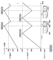
図8(b)は、記録形式として、二つの動画データを同時に記録する設定の場合の記録処理を示すフローチャートである。また、図9は、記録開始後の、バッファ領域に記憶された動画データとメモリカード113に書き込まれるデータ及びファイルシステムの更新動作を示す図である。なお、図9は、前述のように、メイン動画データとして24MB/秒が設定され、サブ動画データとして12MB/秒が設定された場合の状態を示している。
FIG. 8B is a flowchart showing a recording process in the case where the recording format is set to record two moving image data simultaneously. FIG. 9 is a diagram showing the update operation of the moving image data stored in the buffer area, the data written to the
記録待機状態において、ユーザが操作回路115を操作して記録開始を指示すると、撮像素子103からの動画データが画像処理回路105で処理され、フレームメモリ106に記憶される。画像サイズ変換回路108は、フレームメモリ106に記憶された動画データの各画面のサイズを、画像サイズ設定回路202で設定された画像サイズになるように変換し、メモリ114に記憶する。同時記録モードにおいて、画像サイズ変換回路108は、メモリ114から同じ動画データを、同時に記録される二つの動画データとしてそれぞれ読み出す。そして、画像サイズ変換回路108は、同時に記録される各動画データの画面サイズを、それぞれ設定された画面サイズに変換し、メモリ114に記憶する。
In the recording standby state, when the user operates the
符号化回路109は、メモリ114に記憶された動画データを読み出して符号化し、バッファ領域設定回路206で設定されたメモリ114上のバッファ領域に記憶していく。このとき、符号化回路109は、同時に記録される二つの動画データをそれぞれ読み出し、符号化された動画データのデータレートが、設定されたデータレートにより決められた上限のレートを超えないように符号化する(S811)。また、符号化回路109は、符号化されたメイン動画データとサブ動画データをそれぞれ、メモリ114において、前述の様にメイン動画用とサブ動画ように確保されたバッファ領域に記憶する。
The
次に、制御回路116は、バッファ領域に蓄積された、未記録のメイン動画データのデータ量が、閾値T1に達したか否かを判別する(S812)。バッファ領域に蓄積されたメイン動画データのデータ量が閾値T1に達した場合、制御回路116は、ホストコントローラ112に対して、ユニットサイズUz1分のデータ、ここでは16MBのデータを書き込むように指示する。ホストコントローラ112は、メモリカード113に対して書き込みコマンドを発行し、メモリ114上の、メイン動画用のバッファ領域から、指示されたユニットサイズ分のメイン動画データをメモリカードへ書き込む(S813)。この書き込み処理は、図9のメモリカード動作におけるeの期間で示されている。
Next, the
ファイルシステム更新設定回路205には、ユニットサイズUz1毎の更新タイミングが設定されている。そのため、制御回路116は、ユニットサイズ分のデータの書き込みに続いて、ファイルシステムの更新を実行するように、ホストコントローラ112に指示する(S814)。このファイルシステム更新動作は、図9のメモリカード動作におけるfで示した期間に行われる。一つのユニットサイズ分のメイン動画データの書き込みおよびファイルシステム更新は、性能定義ユニット1により320msec以内に完了することが保証されている。また、性能定義ユニット1による書き込み性能は50MB/秒である。一方、メイン動画データのデータレートは24MB/秒であるので、図9において、メモリカードへのメイン動画データの書き込み中、26MB/秒の速度でバッファ領域に蓄積された動画データ量が減少する。
In the file system
ファイルシステムの更新が完了した場合、及び、S812でメイン動画データのデータ量がT1に達していない場合、制御回路116は、バッファ領域に蓄積された、未記録のサブ動画データのデータ量が、閾値T2に達したか否かを判別する(S815)。バッファ領域に蓄積されたサブ動画データのデータ量が閾値T2に達していた場合、制御回路116は、ホストコントローラ112に対して、ユニットサイズUz2分のデータ、ここでは8MBのデータを書き込むように指示する。ホストコントローラ112は、メモリカード113に対して書き込みコマンドを発行し、メモリ114上の、サブ動画用のバッファ領域から、指示されたユニットサイズ分のサブ動画データをメモリカードへ書き込む(S816)。この書き込み処理は、図9のメモリカード動作におけるgの期間で示されている。
When the update of the file system is completed, and when the data amount of the main moving image data has not reached T1 in S812, the
ファイルシステム更新設定回路205には、ユニットサイズUz2毎の更新タイミングが設定されている。そのため、制御回路116は、ユニットサイズ分のデータの書き込みに続いて、ファイルシステムの更新を実行するように、ホストコントローラ112に指示する(S817)。このファイルシステム更新動作は、図9のメモリカード動作におけるhで示した期間に行われる。一つのユニットサイズ分のサブ動画データの書き込みおよびファイルシステム更新は、性能定義ユニット2により200msec以内に完了することが保証されている。また、性能定義ユニット2による書き込み性能は40MB/秒である。一方、サブ動画データのデータレートは12MB/秒であるので、図9において、メモリカードへのサブ動画データの書き込み中、28MB/秒の速度でバッファ領域に蓄積された動画データ量が減少する。
In the file system
ファイルシステムの更新が完了した場合、及び、S815でサブ動画データのデータ量がT1に達していない場合、制御回路116は、記録停止の指示の有無を判別し(S818)、記録停止の指示が無い場合はS811の処理に戻る。
When the update of the file system is completed, and when the data amount of the sub moving image data does not reach T1 in S815, the
本実施形態では、メイン動画データのデータ量が閾値T1に達したか否かの判別を、サブ動画データのデータ量が閾値T2に達したか否かの判別よりも先に実行する。そのため、図9に示すように、記録開始後、メイン動画データのデータ量が閾値T1に達するタイミングと、サブ動画データのデータ量が閾値T2に達するタイミングは、共に時間901となる。そして、メイン動画データの方が先にメモリカード113に書き込まれるため、その間、サブ動画データがバッファ領域に蓄積される。そして、メイン動画データの1回の書き込みが完了した後、時間902においてサブ動画データの書き込みが開始される。時間902の時点でバッファ領域に蓄積されたサブ動画データのデータ量は、11.84MBを超えることがない。
In the present embodiment, the determination as to whether or not the data amount of the main moving image data has reached the threshold value T1 is executed prior to the determination as to whether or not the data amount of the sub moving image data has reached the threshold value T2. Therefore, as shown in FIG. 9, after the start of recording, the timing when the data amount of the main moving image data reaches the threshold value T1 and the timing when the data amount of the sub moving image data reaches the threshold value T2 are both
このように、メモリカード113への書き込み処理において、バッファ領域に蓄積されるメイン動画データとサブ動画データのデータ量は、それぞれバッファ領域として確保されたサイズを超えることはなく、バッファがオーバーフローすることが無い。そのため、動画データの記録が停止されることが無いことを示している。
As described above, in the writing process to the
ユーザにより記録停止が指示された場合、制御回路116は、符号化回路109によるメイン、サブの動画データの符号化を停止するとともに、メモリ114のバッファ領域に対する符号化データの蓄積を停止する(S819)。そして、制御回路116は、ホストコントローラ112に対し、メモリ114のバッファ領域に残っているメイン動画データとサブ動画データの書き込み動作を行い(S820)、ファイルシステム更新を行った後(S821)、記録動作が終了する。なお、S820において書き込みコマンドにより書き込まれるデータのサイズはユニットサイズとは一致しないので、書き込み速度が低下することが考えられる。しかし、すでに記録停止の指示の後の書き込み動作となるため、書き込み性能が低下しても問題はない。
When the recording stop is instructed by the user, the
このように、二つの動画データを同時に記録する場合、それぞれに適正な性能定義ユニットを組み合わせて記録することにより、それぞれのデータレートに対する書き込み性能を維持しながら安定的に動画の記録が行えるという効果がある。また、各動画データの書き込みタイミングが同期するように、性能定義ユニットを組み合わせて選択することにより、それぞれの動画データの記録タイミングが同じになるように書き込みできるので、システムの制御が容易になる。 In this way, when recording two moving image data at the same time, it is possible to record a moving image stably while maintaining the writing performance for each data rate by combining the appropriate performance definition units. There is. Further, by selecting the performance definition units in combination so that the writing timing of each moving image data is synchronized, the recording timing of each moving image data can be written so as to be the same, so that the control of the system becomes easy.
なお、本実施形態における動画データのデータレートは、実施形態に記載した以外の値を設定することも可能である。性能定義ユニットとして、図4のように規定されている場合は、動画データのレートを、一番低いレートの2倍、4倍に設定することにより、何れのレートの動画を記録する場合にも書き込みタイミングをそろえることが可能である。また、性能定義ユニットのユニットサイズが図4に示す値以外の場合には、各性能定義ユニットのユニットサイズの比に応じて、記録される動画データのレートを決めることで、書き込みタイミングをそろえることが可能である。 Note that the data rate of the moving image data in this embodiment can be set to a value other than that described in the embodiment. When the performance definition unit is defined as shown in FIG. 4, the video data rate is set to be twice or four times the lowest rate so that any rate of video can be recorded. It is possible to align the write timing. If the unit size of the performance definition unit is other than the values shown in FIG. 4, the write timing can be aligned by determining the rate of the moving image data to be recorded according to the unit size ratio of each performance definition unit. Is possible.
●(第2の実施形態)
次に、第2の実施形態を説明する。第1の実施形態では、性能定義ユニットとして、ユニットサイズ分のデータの書き込み及びFATの更新処理を決められた時間内に実行することが規定されていた。
● (Second Embodiment)
Next, a second embodiment will be described. In the first embodiment, the performance definition unit is defined to execute data writing and FAT update processing for a unit size within a predetermined time.
本実施形態では、メモリカード113に対して、データの書き込み処理と、管理情報の書き込み処理(FATの更新処理)とが、別の性能定義ユニットにより規定される。図10は、本実施形態のメモリカード113で定義されている性能定義ユニットによるアクセス条件を示す図である。それぞれ、性能定義ユニット5によるアクセス条件は、ユニットサイズ=16MB、Tuw=300msecであり、書き込み速度として53MB/secの性能を持つ。性能定義ユニット6によるアクセス条件は、ユニットサイズ=8MB、Tuw=180msecであり、書き込み速度として44MB/secの性能を持つ。性能定義ユニット7によるアクセス条件は、ユニットサイズ=4MB、Tuw=110msecであり、書き込み速度として36MB/secの性能を持つ。性能定義ユニット8によるアクセス条件は、ユニットサイズ=2MB、Tuw=80msecであり、書き込み速度として25MB/secの性能を持つ。また、性能定義ユニット9は、ファイルシステムの更新のためのアクセス条件を定義する。
In the present embodiment, a data write process and a management information write process (FAT update process) are defined for the
本実施形態においても、デジタルビデオカメラ100の構成は第1の実施形態と同様である。以下、一つの動画データを記録する場合の動作を説明する。本実施形態では、図10のように、FAT更新のための性能定義ユニットが定義されている。そのため、動画データの1回の書き込み毎にFAT更新を行う以外に、複数回の動画書き込み毎にFAT更新を実行するように構成することも可能である。この場合、FAT更新の実行タイミング以外においては、選択された性能定義ユニットにおけるユニットサイズ分の動画データの書き込みが連続して実行される。
Also in this embodiment, the configuration of the
本実施形態において、ユーザにより、記録される動画の画面サイズ、データレート及び記録形式が設定されると図5(a)の処理が実行される。制御回路116は、設定された記録形式により、一つの動画を記録するか、或いは、二つの動画を同時に記録するかを判別する(S501)。一つの動画を記録する設定の場合、制御回路116は、ユーザの設定に基づいて、画像サイズ設定回路202に画面サイズを設定し、データレート設定回路203に動画のデータレートを設定する(S502)。次に、ユニットサイズ設定回路204は、設定された記録形式と動画のデータレートに基づき、ユニットサイズを算出し、設定する(S503)。具体的には、設定された動画のデータレートを上回る書き込み速度を持つ性能定義ユニットによるユニットサイズが設定される。例えば、本実施形態では、動画データのデータレートとして50MB/秒が設定された場合を説明する。この場合、図10に示す性能定義ユニットのうち、これを上回る書き込み速度を持つ性能定義ユニット5によるユニットサイズ16MBが設定される。
In the present embodiment, when the screen size, data rate, and recording format of a moving image to be recorded are set by the user, the processing in FIG. 5A is executed. The
さらに、制御回路116は、ファイルシステム更新設定回路205にファイルシステム更新の頻度を設定する(S504)。本実施形態では、ユニットサイズの動画データの書き込みを3回実行する度にFATを更新するように設定する。なお、FATの更新間隔を長くするほど記録する動画データのレートを高くすることができるが、記録中にバッテリが外れた等により瞬断が発生した場合に、正常に再生できない動画の長さが長くなる。
Further, the
次に、バッファ領域設定回路206は、設定されたユニットサイズから、記録時に必要となるバッファ領域のサイズを設定する。そして、設定したサイズの領域を、動画データのためのバッファメモリ領域としてメモリ114内に確保する(S505)。性能定義ユニット6によれば、ユニットサイズ(Uz)が16MBなので、バッファ領域としては16MBより大きいサイズが確保される。また、メモリカード113に対する、動画データの書き込みタイミングを決めるために用いられる、バッファメモリ領域のデータ蓄積量の閾値Tとして、ユニットサイズを設定する。
Next, the buffer
次に、本実施形態における動画データの記録処理を説明する。図11は、本実施形態の記録処理を示すフローチャートである。また、図12は、記録開始後の、バッファ領域に記憶された動画データとメモリカード113に書き込まれるデータ及びファイルシステムの更新動作を示す図である。なお、図12は、前述の様に、性能定義ユニット6が選択され、更に、動画データの3回の書き込み毎にFAT更新が行われる場合を示している。
Next, moving image data recording processing according to the present embodiment will be described. FIG. 11 is a flowchart showing the recording process of the present embodiment. FIG. 12 is a diagram showing the update operation of the moving image data stored in the buffer area, the data written to the
記録待機状態において、ユーザが操作回路115を操作して記録開始を指示すると、撮像素子103からの動画データが画像処理回路105で処理され、フレームメモリ106に記憶される。画像サイズ変換回路108は、フレームメモリ106に記憶された動画データの各画面のサイズを、画像サイズ設定回路202で設定された画像サイズになるように変換し、メモリ114に記憶する。符号化回路109は、メモリ114に記憶された動画データを読み出して符号化し、バッファ領域設定回路206で設定されたメモリ114上のバッファ領域に記憶していく。このとき、符号化回路109は、符号化された動画データのデータレートが、設定されたデータレートにより決められた上限のレートを超えないように符号化する(S1101)。
In the recording standby state, when the user operates the
次に、制御回路116は、バッファ領域に蓄積された、未記録の動画データのデータ量が、閾値Tに達したか否かを判別する(S1102)。バッファ領域に蓄積された動画データのデータ量が閾値Tを超えた場合、制御回路116は、ホストコントローラ112に対して、ユニットサイズUz分のデータ、ここでは16MBのデータを書き込むように指示する。ホストコントローラ112は、メモリカード113に対して書き込みコマンドを発行し、メモリ114上のバッファ領域から、指示されたユニットサイズ分の動画データをメモリカードへ書き込む(S1103)。この書き込み処理は、図12のメモリカード動作におけるiの期間で示されている。
Next, the
1回の書き込みが完了すると、制御回路116は、連続したN回、ここでは3回の書き込みが完了したか否かを判別する(S1104)。N回の書き込みが完了していない場合、S1103に戻り、制御回路116は、ホストコントローラ112に対して、再度、ユニットサイズ分の動画データの書き込みを指示する。
When one writing is completed, the
このように、N回の書き込みが完了すると、制御回路116は、ファイルシステムの更新を実行するように、ホストコントローラ112に指示する(S1105)。このファイルシステム更新動作は、図12のメモリカード動作におけるjで示した期間に行われる。ファイルシステムの更新が完了すると、制御回路116は、記録停止の指示を判別する(S1106)。記録停止の指示が無い場合はS1102に戻る。即ち、FAT更新後、再度、バッファ領域に蓄積された動画データのデータ量が閾値Tに達した時点で、メモリカード113に対する動画データの書き込みが開始される。
Thus, when N times of writing are completed, the
このように、一つのユニットサイズ分の動画データの書き込みは300msec以内に完了することが保証されるので、3回連続でユニットサイズ分の動画の書き込みが実行されることで、16x3=48MBが900msecで書きこまれることが保証される。また、ファイルシステム更新は、性能定義ユニット9により20msec以内に完了することが保証されている。 As described above, writing of moving image data for one unit size is guaranteed to be completed within 300 msec, so that writing of moving images for the unit size is executed three times in succession, so that 16 × 3 = 48 MB is 900 msec. Is guaranteed to be written in. The file system update is guaranteed to be completed within 20 msec by the performance definition unit 9.
そのため、3回連続して16MBの動画データの書き込みを実行した後にFATを更新した場合でも、バッファ領域に蓄積されるデータ量は16MBを超えることはなく、バッファがオーバーフローすることが無い。そのため、動画データの記録が停止されることが無いことを示している。 Therefore, even when the FAT is updated after writing 16 MB of moving image data three times in succession, the amount of data stored in the buffer area does not exceed 16 MB, and the buffer does not overflow. Therefore, it indicates that the recording of moving image data is not stopped.
ユーザにより記録停止が指示された場合、制御回路116は、符号化回路109による動画データの符号化を停止するとともに、メモリ114に対する符号化データの蓄積を停止する(S1107)。そして、制御回路116は、ホストコントローラ112に対し、バッファ領域に残っている動画データの書き込み動作を行い(S1108)、ファイルシステム更新を行った後(S1109)、記録動作が終了する。
When the user gives an instruction to stop recording, the
このように、本実施形態では、データの書き込みとFAT更新のアクセス条件が別の性能定義ユニットにより規定される。そして、FAT更新の頻度を適宜設定することで、動画データのレートを、性能定義ユニットで定義される書き込み速度に近いレートに設定することが可能となる。 As described above, in this embodiment, access conditions for data writing and FAT update are defined by separate performance definition units. Then, by appropriately setting the frequency of FAT update, it is possible to set the rate of moving image data to a rate close to the writing speed defined by the performance definition unit.
(その他の実施形態)
また、本発明は、以下の処理を実行することによっても実現される。即ち、上述した実施形態の機能を実現するソフトウェア(プログラム)を、ネットワーク又は各種記憶媒体を介してシステム或いは装置に供給し、そのシステム或いは装置のコンピュータ(またはCPUやMPU等)がプログラムを読み出して実行する処理である。
(Other embodiments)
The present invention can also be realized by executing the following processing. That is, software (program) that realizes the functions of the above-described embodiments is supplied to a system or apparatus via a network or various storage media, and a computer (or CPU, MPU, or the like) of the system or apparatus reads the program. It is a process to be executed.
Claims (9)
記録媒体に対して書き込みコマンドを出力することにより、前記動画データを前記記録媒体に書き込む記録手段と、
複数の所定のデータ量から、1回の前記書き込みコマンドによって前記記録媒体に書き込まれる動画データのデータ量を設定し、前記設定したデータ量の動画データを1回の前記書き込みコマンドにより前記記録媒体に書き込むように前記記録手段を制御する制御手段と、
所定のファイルシステムに従い、前記記録媒体に記録された動画データをファイルとして管理する管理手段と、を有し、
前記複数の所定のデータ量それぞれについて、前記記録媒体の書き込み速度と、1回の前記書き込みコマンドによるデータの書き込みのための実行時間とが、前記記録媒体に規定されており、
前記記録手段は、前記ファイルシステムに対応した管理情報を前記記録媒体に記録し、前記書き込みコマンドよるデータの書き込みのための実行時間には、前記管理情報を前記記録媒体に記録するための時間が含まれていることを特徴とする記録装置。 Processing means for generating video data;
Recording means for writing the moving image data to the recording medium by outputting a write command to the recording medium;
A data amount of moving image data written to the recording medium by one write command is set from a plurality of predetermined data amounts, and the moving image data having the set data amount is set on the recording medium by one write command. Control means for controlling the recording means to write;
In accordance with a predetermined file system, has a management means for managing the moving image data recorded on the recording medium as a file,
For each of the plurality of predetermined data amounts, a writing speed of the recording medium and an execution time for writing data by one writing command are defined in the recording medium,
The recording means records management information corresponding to the file system on the recording medium, and an execution time for writing data by the write command includes a time for recording the management information on the recording medium. record apparatus shall be the feature that it contains.
記録媒体に対して書き込みコマンドを出力することにより、前記動画データを前記記録媒体に書き込む記録手段と、
複数の所定のデータ量から、1回の前記書き込みコマンドによって前記記録媒体に書き込まれる動画データのデータ量を設定し、前記設定したデータ量の動画データを1回の前記書き込みコマンドにより前記記録媒体に書き込むように前記記録手段を制御する制御手段と、
所定のファイルシステムに従い、前記記録媒体に記録された動画データをファイルとして管理する管理手段と、を有し、
前記複数の所定のデータ量それぞれについて、前記記録媒体の書き込み速度と、1回の前記書き込みコマンドによるデータの書き込みのための実行時間とが、前記記録媒体に規定されており、
前記記録手段は、
前記ファイルシステムに対応した管理情報を前記記録媒体に記録し、
前記記録媒体に対して更新を指示するコマンドを出力することにより前記記録媒体に前記管理情報を記録し、
1回の前記更新を指示するコマンドによる前記管理情報の記録のための実行時間が、前記記録媒体に規定されていることを特徴とする記録装置。 Processing means for generating video data;
Recording means for writing the moving image data to the recording medium by outputting a write command to the recording medium;
A data amount of moving image data written to the recording medium by one write command is set from a plurality of predetermined data amounts, and the moving image data having the set data amount is set on the recording medium by one write command. Control means for controlling the recording means to write;
In accordance with a predetermined file system, has a management means for managing the moving image data recorded on the recording medium as a file,
For each of the plurality of predetermined data amounts, a writing speed of the recording medium and an execution time for writing data by one writing command are defined in the recording medium,
The recording means includes
Management information corresponding to the file system is recorded on the recording medium,
Recording the management information on the recording medium by outputting a command to instruct the updating to the recording medium;
Run time for recording the management information by the command for instructing one of the updates, characterized in that it is defined in the recording medium record device.
前記制御手段は、前記動画データのデータレートに応じて、前記複数の所定のデータ量から、1回の前記書き込みコマンドによって前記記録媒体に書き込まれる動画データのデータ量を設定することを特徴とする請求項1または請求項2に記載の記録装置。 A setting unit for setting a data rate of the moving image data generated by the processing unit;
The control means sets a data amount of moving image data written to the recording medium by one write command from the plurality of predetermined data amounts according to a data rate of the moving image data. The recording apparatus according to claim 1 or 2 .
前記制御手段は、前記モードにおいて同時に記録される前記二つの動画データのデータレートに応じて、前記二つの動画データをそれぞれ記録するために、1回の前記書き込みコマンドによって前記記録媒体に書き込まれる動画データのデータ量を設定することを特徴とする請求項4に記載の記録装置。 The recording means includes a mode for simultaneously recording two moving image data on the recording medium,
The control means is configured to record a moving image written on the recording medium by a single write command in order to record the two moving image data in accordance with a data rate of the two moving image data recorded simultaneously in the mode. The recording apparatus according to claim 4 , wherein a data amount of data is set.
記録媒体に対して書き込みコマンドを出力することにより、前記動画データを前記記録媒体に書き込む記録手段と、
所定のファイルシステムに従い、前記記録媒体に記録された動画データをファイルとして管理する管理手段と、を有する記録装置の制御方法であって、
複数の所定のデータ量から、1回の前記書き込みコマンドによって前記記録媒体に書き込まれる動画データのデータ量を設定し、前記設定したデータ量の動画データを1回の前記書き込みコマンドにより前記記録媒体に書き込むように制御手段が前記記録手段を制御する制御ステップを有し、
前記複数の所定のデータ量それぞれについて、前記記録媒体の書き込み速度と、1回の前記書き込みコマンドによるデータの書き込みのための実行時間とが、前記記録媒体に規定されており、
前記記録手段は、前記ファイルシステムに対応した管理情報を前記記録媒体に記録し、前記書き込みコマンドよるデータの書き込みのための実行時間には、前記管理情報を前記記録媒体に記録するための時間が含まれていることを特徴とする記録装置の制御方法。 Processing means for generating video data;
Recording means for writing the moving image data to the recording medium by outputting a write command to the recording medium;
A management unit for managing moving image data recorded on the recording medium as a file according to a predetermined file system ,
A data amount of moving image data written to the recording medium by one write command is set from a plurality of predetermined data amounts, and the moving image data having the set data amount is set on the recording medium by one write command. control means to write that have a control step for controlling the recording device,
For each of the plurality of predetermined data amounts, a writing speed of the recording medium and an execution time for writing data by one writing command are defined in the recording medium,
The recording means records management information corresponding to the file system on the recording medium, and an execution time for writing data by the write command includes a time for recording the management information on the recording medium. control method for a recording apparatus, characterized in that it contains.
記録媒体に対して書き込みコマンドを出力することにより、前記動画データを前記記録媒体に書き込む記録手段と、 Recording means for writing the moving image data to the recording medium by outputting a write command to the recording medium;
所定のファイルシステムに従い、前記記録媒体に記録された動画データをファイルとして管理する管理手段と、を有する記録装置の制御方法であって、 A management unit for managing moving image data recorded on the recording medium as a file according to a predetermined file system,
複数の所定のデータ量から、1回の前記書き込みコマンドによって前記記録媒体に書き込まれる動画データのデータ量を設定し、前記設定したデータ量の動画データを1回の前記書き込みコマンドにより前記記録媒体に書き込むように制御手段が前記記録手段を制御する制御ステップを有し、 A data amount of moving image data written to the recording medium by one write command is set from a plurality of predetermined data amounts, and the moving image data having the set data amount is set on the recording medium by one write command. The control means has a control step for controlling the recording means to write,
前記複数の所定のデータ量それぞれについて、前記記録媒体の書き込み速度と、1回の前記書き込みコマンドによるデータの書き込みのための実行時間とが、前記記録媒体に規定されており、 For each of the plurality of predetermined data amounts, a writing speed of the recording medium and an execution time for writing data by one writing command are defined in the recording medium,
前記記録手段は、 The recording means includes
前記ファイルシステムに対応した管理情報を前記記録媒体に記録し、 Management information corresponding to the file system is recorded on the recording medium,
前記記録媒体に対して更新を指示するコマンドを出力することにより前記記録媒体に前記管理情報を記録し、 Recording the management information on the recording medium by outputting a command to instruct the updating to the recording medium;
1回の前記更新を指示するコマンドによる前記管理情報の記録のための実行時間が、前記記録媒体に規定されていることを特徴とする記録装置の制御方法。 An execution time for recording the management information by a command for instructing one update is defined in the recording medium.
記録媒体に対して書き込みコマンドを出力することにより、前記動画データを前記記録媒体に書き込む記録手段と、
所定のファイルシステムに従い、前記記録媒体に記録された動画データをファイルとして管理する管理手段と、を有する記録装置のコンピュータを、請求項1乃至請求項5のいずれか1項に記載の記録装置の、前記処理手段および前記記録手段を除く各手段として機能させるためのプログラム。 Processing means for generating video data;
Recording means for writing the moving image data to the recording medium by outputting a write command to the recording medium;
According to a predetermined file system, said management means for managing the moving image data recorded on the recording medium as a file, the computer of the recording apparatus having the recording apparatus according to any one of claims 1 to 5 , A program for functioning as each means excluding the processing means and the recording means.
Priority Applications (1)
| Application Number | Priority Date | Filing Date | Title |
|---|---|---|---|
| JP2013268610A JP6373002B2 (en) | 2013-12-26 | 2013-12-26 | Recording apparatus and control method thereof |
Applications Claiming Priority (1)
| Application Number | Priority Date | Filing Date | Title |
|---|---|---|---|
| JP2013268610A JP6373002B2 (en) | 2013-12-26 | 2013-12-26 | Recording apparatus and control method thereof |
Publications (3)
| Publication Number | Publication Date |
|---|---|
| JP2015126323A JP2015126323A (en) | 2015-07-06 |
| JP2015126323A5 JP2015126323A5 (en) | 2017-02-09 |
| JP6373002B2 true JP6373002B2 (en) | 2018-08-15 |
Family
ID=53536767
Family Applications (1)
| Application Number | Title | Priority Date | Filing Date |
|---|---|---|---|
| JP2013268610A Active JP6373002B2 (en) | 2013-12-26 | 2013-12-26 | Recording apparatus and control method thereof |
Country Status (1)
| Country | Link |
|---|---|
| JP (1) | JP6373002B2 (en) |
Families Citing this family (1)
| Publication number | Priority date | Publication date | Assignee | Title |
|---|---|---|---|---|
| CN113342155A (en) * | 2020-02-18 | 2021-09-03 | 浙江宇视科技有限公司 | Data storage method, device, equipment and storage medium |
Family Cites Families (3)
| Publication number | Priority date | Publication date | Assignee | Title |
|---|---|---|---|---|
| JP4392601B2 (en) * | 2004-05-07 | 2010-01-06 | パナソニック株式会社 | Data access device and recording medium |
| JP2008176455A (en) * | 2007-01-17 | 2008-07-31 | Matsushita Electric Ind Co Ltd | Information recorder, controller, access device, and access speed guaranteeing system |
| JP2013225760A (en) * | 2012-04-20 | 2013-10-31 | Sony Corp | Recording apparatus, imaging and recording apparatus, recording method, and program |
-
2013
- 2013-12-26 JP JP2013268610A patent/JP6373002B2/en active Active
Also Published As
| Publication number | Publication date |
|---|---|
| JP2015126323A (en) | 2015-07-06 |
Similar Documents
| Publication | Publication Date | Title |
|---|---|---|
| JP6356970B2 (en) | Recording apparatus and control method of recording apparatus | |
| JP6137980B2 (en) | Recording apparatus and control method thereof | |
| JP6784626B2 (en) | Recording device, control method, and program | |
| JP2016220003A (en) | Moving image generation device, moving image generation method, and program | |
| JP6784631B2 (en) | Recording / playback device, control method of recording / playback device, and program | |
| US20140241697A1 (en) | Recording apparatus, recording method, and program | |
| JP6373002B2 (en) | Recording apparatus and control method thereof | |
| JP2016009280A (en) | Recording device | |
| US10439619B2 (en) | Recording apparatus, control method, and storage medium | |
| JP6417094B2 (en) | RECORDING / REPRODUCING DEVICE, RECORDING / REPRODUCING DEVICE CONTROL METHOD, AND COMPUTER PROGRAM | |
| JP6356972B2 (en) | RECORDING DEVICE, IMAGING DEVICE, AND RECORDING DEVICE CONTROL METHOD | |
| JP6857066B2 (en) | Recording / playback device, control method of recording / playback device, and program | |
| US10950274B2 (en) | Image recording apparatus, method for controlling same, and non-transitory computer-readable storage medium | |
| JP7171337B2 (en) | IMAGING DEVICE, IMAGE RECORDING METHOD AND PROGRAM | |
| JP6066718B2 (en) | Imaging apparatus, control method thereof, and program | |
| JP2020091696A (en) | Recording and reproducing apparatus | |
| JP2017022559A (en) | Recording device and control method for recording device | |
| JP6023512B2 (en) | Recording apparatus and method | |
| JP6112972B2 (en) | Imaging device | |
| JP2018201102A (en) | Imaging apparatus | |
| JP2008103924A (en) | Imaging apparatus | |
| JP6504927B2 (en) | Recording apparatus and control method of recording apparatus | |
| JP2014207613A (en) | Imaging apparatus and imaging method | |
| JP2021013064A (en) | Recording device, recording method, and program | |
| JP2005333437A (en) | Image photographing apparatus |
Legal Events
| Date | Code | Title | Description |
|---|---|---|---|
| A521 | Request for written amendment filed |
Free format text: JAPANESE INTERMEDIATE CODE: A523 Effective date: 20161226 |
|
| A621 | Written request for application examination |
Free format text: JAPANESE INTERMEDIATE CODE: A621 Effective date: 20161226 |
|
| A977 | Report on retrieval |
Free format text: JAPANESE INTERMEDIATE CODE: A971007 Effective date: 20171025 |
|
| A131 | Notification of reasons for refusal |
Free format text: JAPANESE INTERMEDIATE CODE: A131 Effective date: 20171117 |
|
| A521 | Request for written amendment filed |
Free format text: JAPANESE INTERMEDIATE CODE: A523 Effective date: 20180112 |
|
| TRDD | Decision of grant or rejection written | ||
| A01 | Written decision to grant a patent or to grant a registration (utility model) |
Free format text: JAPANESE INTERMEDIATE CODE: A01 Effective date: 20180619 |
|
| A61 | First payment of annual fees (during grant procedure) |
Free format text: JAPANESE INTERMEDIATE CODE: A61 Effective date: 20180717 |
|
| R151 | Written notification of patent or utility model registration |
Ref document number: 6373002 Country of ref document: JP Free format text: JAPANESE INTERMEDIATE CODE: R151 |