JP6372965B2 - Radar measurement method using multiple different fields of view - Google Patents
Radar measurement method using multiple different fields of view Download PDFInfo
- Publication number
- JP6372965B2 JP6372965B2 JP2017518412A JP2017518412A JP6372965B2 JP 6372965 B2 JP6372965 B2 JP 6372965B2 JP 2017518412 A JP2017518412 A JP 2017518412A JP 2017518412 A JP2017518412 A JP 2017518412A JP 6372965 B2 JP6372965 B2 JP 6372965B2
- Authority
- JP
- Japan
- Prior art keywords
- view
- measurement
- columns
- different
- column
- Prior art date
- Legal status (The legal status is an assumption and is not a legal conclusion. Google has not performed a legal analysis and makes no representation as to the accuracy of the status listed.)
- Active
Links
Images


Classifications
-
- G—PHYSICS
- G01—MEASURING; TESTING
- G01S—RADIO DIRECTION-FINDING; RADIO NAVIGATION; DETERMINING DISTANCE OR VELOCITY BY USE OF RADIO WAVES; LOCATING OR PRESENCE-DETECTING BY USE OF THE REFLECTION OR RERADIATION OF RADIO WAVES; ANALOGOUS ARRANGEMENTS USING OTHER WAVES
- G01S13/00—Systems using the reflection or reradiation of radio waves, e.g. radar systems; Analogous systems using reflection or reradiation of waves whose nature or wavelength is irrelevant or unspecified
- G01S13/02—Systems using reflection of radio waves, e.g. primary radar systems; Analogous systems
- G01S13/06—Systems determining position data of a target
- G01S13/42—Simultaneous measurement of distance and other co-ordinates
- G01S13/424—Stacked beam radar
-
- G—PHYSICS
- G01—MEASURING; TESTING
- G01S—RADIO DIRECTION-FINDING; RADIO NAVIGATION; DETERMINING DISTANCE OR VELOCITY BY USE OF RADIO WAVES; LOCATING OR PRESENCE-DETECTING BY USE OF THE REFLECTION OR RERADIATION OF RADIO WAVES; ANALOGOUS ARRANGEMENTS USING OTHER WAVES
- G01S7/00—Details of systems according to groups G01S13/00, G01S15/00, G01S17/00
- G01S7/02—Details of systems according to groups G01S13/00, G01S15/00, G01S17/00 of systems according to group G01S13/00
- G01S7/35—Details of non-pulse systems
- G01S7/352—Receivers
- G01S7/354—Extracting wanted echo-signals
-
- G—PHYSICS
- G01—MEASURING; TESTING
- G01S—RADIO DIRECTION-FINDING; RADIO NAVIGATION; DETERMINING DISTANCE OR VELOCITY BY USE OF RADIO WAVES; LOCATING OR PRESENCE-DETECTING BY USE OF THE REFLECTION OR RERADIATION OF RADIO WAVES; ANALOGOUS ARRANGEMENTS USING OTHER WAVES
- G01S13/00—Systems using the reflection or reradiation of radio waves, e.g. radar systems; Analogous systems using reflection or reradiation of waves whose nature or wavelength is irrelevant or unspecified
- G01S13/02—Systems using reflection of radio waves, e.g. primary radar systems; Analogous systems
- G01S13/0209—Systems with very large relative bandwidth, i.e. larger than 10 %, e.g. baseband, pulse, carrier-free, ultrawideband
-
- G—PHYSICS
- G01—MEASURING; TESTING
- G01S—RADIO DIRECTION-FINDING; RADIO NAVIGATION; DETERMINING DISTANCE OR VELOCITY BY USE OF RADIO WAVES; LOCATING OR PRESENCE-DETECTING BY USE OF THE REFLECTION OR RERADIATION OF RADIO WAVES; ANALOGOUS ARRANGEMENTS USING OTHER WAVES
- G01S13/00—Systems using the reflection or reradiation of radio waves, e.g. radar systems; Analogous systems using reflection or reradiation of waves whose nature or wavelength is irrelevant or unspecified
- G01S13/02—Systems using reflection of radio waves, e.g. primary radar systems; Analogous systems
- G01S13/06—Systems determining position data of a target
- G01S13/08—Systems for measuring distance only
- G01S13/32—Systems for measuring distance only using transmission of continuous waves, whether amplitude-, frequency-, or phase-modulated, or unmodulated
- G01S13/34—Systems for measuring distance only using transmission of continuous waves, whether amplitude-, frequency-, or phase-modulated, or unmodulated using transmission of continuous, frequency-modulated waves while heterodyning the received signal, or a signal derived therefrom, with a locally-generated signal related to the contemporaneously transmitted signal
- G01S13/343—Systems for measuring distance only using transmission of continuous waves, whether amplitude-, frequency-, or phase-modulated, or unmodulated using transmission of continuous, frequency-modulated waves while heterodyning the received signal, or a signal derived therefrom, with a locally-generated signal related to the contemporaneously transmitted signal using sawtooth modulation
-
- G—PHYSICS
- G01—MEASURING; TESTING
- G01S—RADIO DIRECTION-FINDING; RADIO NAVIGATION; DETERMINING DISTANCE OR VELOCITY BY USE OF RADIO WAVES; LOCATING OR PRESENCE-DETECTING BY USE OF THE REFLECTION OR RERADIATION OF RADIO WAVES; ANALOGOUS ARRANGEMENTS USING OTHER WAVES
- G01S13/00—Systems using the reflection or reradiation of radio waves, e.g. radar systems; Analogous systems using reflection or reradiation of waves whose nature or wavelength is irrelevant or unspecified
- G01S13/02—Systems using reflection of radio waves, e.g. primary radar systems; Analogous systems
- G01S13/06—Systems determining position data of a target
- G01S13/42—Simultaneous measurement of distance and other co-ordinates
-
- G—PHYSICS
- G01—MEASURING; TESTING
- G01S—RADIO DIRECTION-FINDING; RADIO NAVIGATION; DETERMINING DISTANCE OR VELOCITY BY USE OF RADIO WAVES; LOCATING OR PRESENCE-DETECTING BY USE OF THE REFLECTION OR RERADIATION OF RADIO WAVES; ANALOGOUS ARRANGEMENTS USING OTHER WAVES
- G01S13/00—Systems using the reflection or reradiation of radio waves, e.g. radar systems; Analogous systems using reflection or reradiation of waves whose nature or wavelength is irrelevant or unspecified
- G01S13/02—Systems using reflection of radio waves, e.g. primary radar systems; Analogous systems
- G01S13/50—Systems of measurement based on relative movement of target
- G01S13/52—Discriminating between fixed and moving objects or between objects moving at different speeds
- G01S13/536—Discriminating between fixed and moving objects or between objects moving at different speeds using transmission of continuous unmodulated waves, amplitude-, frequency-, or phase-modulated waves
-
- G—PHYSICS
- G01—MEASURING; TESTING
- G01S—RADIO DIRECTION-FINDING; RADIO NAVIGATION; DETERMINING DISTANCE OR VELOCITY BY USE OF RADIO WAVES; LOCATING OR PRESENCE-DETECTING BY USE OF THE REFLECTION OR RERADIATION OF RADIO WAVES; ANALOGOUS ARRANGEMENTS USING OTHER WAVES
- G01S13/00—Systems using the reflection or reradiation of radio waves, e.g. radar systems; Analogous systems using reflection or reradiation of waves whose nature or wavelength is irrelevant or unspecified
- G01S13/02—Systems using reflection of radio waves, e.g. primary radar systems; Analogous systems
- G01S13/50—Systems of measurement based on relative movement of target
- G01S13/58—Velocity or trajectory determination systems; Sense-of-movement determination systems
- G01S13/583—Velocity or trajectory determination systems; Sense-of-movement determination systems using transmission of continuous unmodulated waves, amplitude-, frequency-, or phase-modulated waves and based upon the Doppler effect resulting from movement of targets
- G01S13/584—Velocity or trajectory determination systems; Sense-of-movement determination systems using transmission of continuous unmodulated waves, amplitude-, frequency-, or phase-modulated waves and based upon the Doppler effect resulting from movement of targets adapted for simultaneous range and velocity measurements
-
- G—PHYSICS
- G01—MEASURING; TESTING
- G01S—RADIO DIRECTION-FINDING; RADIO NAVIGATION; DETERMINING DISTANCE OR VELOCITY BY USE OF RADIO WAVES; LOCATING OR PRESENCE-DETECTING BY USE OF THE REFLECTION OR RERADIATION OF RADIO WAVES; ANALOGOUS ARRANGEMENTS USING OTHER WAVES
- G01S13/00—Systems using the reflection or reradiation of radio waves, e.g. radar systems; Analogous systems using reflection or reradiation of waves whose nature or wavelength is irrelevant or unspecified
- G01S13/88—Radar or analogous systems specially adapted for specific applications
- G01S13/93—Radar or analogous systems specially adapted for specific applications for anti-collision purposes
- G01S13/931—Radar or analogous systems specially adapted for specific applications for anti-collision purposes of land vehicles
-
- G—PHYSICS
- G01—MEASURING; TESTING
- G01S—RADIO DIRECTION-FINDING; RADIO NAVIGATION; DETERMINING DISTANCE OR VELOCITY BY USE OF RADIO WAVES; LOCATING OR PRESENCE-DETECTING BY USE OF THE REFLECTION OR RERADIATION OF RADIO WAVES; ANALOGOUS ARRANGEMENTS USING OTHER WAVES
- G01S13/00—Systems using the reflection or reradiation of radio waves, e.g. radar systems; Analogous systems using reflection or reradiation of waves whose nature or wavelength is irrelevant or unspecified
- G01S13/02—Systems using reflection of radio waves, e.g. primary radar systems; Analogous systems
- G01S2013/0236—Special technical features
- G01S2013/0245—Radar with phased array antenna
-
- G—PHYSICS
- G01—MEASURING; TESTING
- G01S—RADIO DIRECTION-FINDING; RADIO NAVIGATION; DETERMINING DISTANCE OR VELOCITY BY USE OF RADIO WAVES; LOCATING OR PRESENCE-DETECTING BY USE OF THE REFLECTION OR RERADIATION OF RADIO WAVES; ANALOGOUS ARRANGEMENTS USING OTHER WAVES
- G01S7/00—Details of systems according to groups G01S13/00, G01S15/00, G01S17/00
- G01S7/02—Details of systems according to groups G01S13/00, G01S15/00, G01S17/00 of systems according to group G01S13/00
- G01S7/35—Details of non-pulse systems
- G01S7/352—Receivers
- G01S7/356—Receivers involving particularities of FFT processing
Description
本発明は、視野角および/または検出距離の点で異なっている異なる複数の視界を備えた送信アンテナを用いてFMCWレーダー測定を行い、受信した信号を混合させてベースバンド信号を形成するようにした、レーダー対象物の位置を決定するための方法に関するものである。
特に、本発明は、複数の視界のうちの少なくとも2つの視界に対し、それぞれの測定が角度分解能測定であり、該角度分解能測定を、送信および/または受信に使用される複数のアンテナの選択を異ならせて実施し、レーダー目標物の位置を決定するため、それぞれの視界の測定のベースバンド信号の2次元スペクトルにおいてピークを求め、それぞれの視界で位置決定されるレーダー目標物の角度位置を、前記ベースバンド信号の2次元スペクトルで前記レーダー目標物に対応するピークの位置での振幅および/または位相に基づいて特定し、前記ベースバンド信号が送信および/または受信に使用する前記アンテナの異なる選定に対し得られるようにした方法に関する。
さらに、本発明は、上記方法を実施するために構成された、特に自動車用のレーダーセンサに関する。
The present invention performs FMCW radar measurements using transmit antennas with different views that differ in view angle and / or detection distance, and mixes the received signals to form a baseband signal And a method for determining the position of a radar object.
In particular, the present invention relates to at least two views of a plurality of views, each measurement being an angular resolution measurement, and the angular resolution measurement is selected from a plurality of antennas used for transmission and / or reception. In order to carry out differently and determine the position of the radar target, find the peak in the two-dimensional spectrum of the baseband signal for each field of view measurement, and determine the angular position of the radar target that is positioned in each field of view, Different selections of the antennas that the baseband signal uses for transmission and / or reception, identified based on the amplitude and / or phase at the location of the peak corresponding to the radar target in the two-dimensional spectrum of the baseband signal It is related with the method made to obtain for.
Furthermore, the invention relates to a radar sensor, in particular for motor vehicles, configured for carrying out the above method.
自動車では、交通環境を検知するため、特に他車の位置を検出するためにFMCMレーダーセンサが使用される。位置検出結果は種々のアシスト機能のために利用でき、たとえば自動車間距離制御、自動衝突警告、或いは、実際に衝突の危険がある場合に緊急ブレーキ過程を自動的に起動させるためにも利用できる。 In automobiles, FMCM radar sensors are used to detect the traffic environment, in particular to detect the position of other cars. The position detection result can be used for various assist functions, for example, inter-vehicle distance control, automatic collision warning, or for automatically starting an emergency braking process when there is an actual danger of collision.
FMCW(Frequency Modulated Continuous Wave)レーダーセンサの場合、周波数を傾斜状に変調させた送信信号が使用される。信号は、傾斜波が推移している間に連続的に送信される。受信信号から、送信信号との混合によりベースバンド信号が生成され、該ベースバンド信号はサンプリングされ、評価される。 In the case of an FMCW (Frequency Modulated Continuous Wave) radar sensor, a transmission signal having a frequency modulated in an inclined manner is used. The signal is transmitted continuously while the ramp is changing. A baseband signal is generated from the received signal by mixing with the transmitted signal, and the baseband signal is sampled and evaluated.
ベースバンド信号の周波数は、所定時点で送信される信号と、同じ時点で受信された信号との間の周波数差に対応している。送信信号の周波数変調に基づき、この周波数差は、レーダーセンサから対象物まで、およびその逆の方向での信号のランニングタイムに、したがって対象物との距離に依存している。しかしながら、周波数差は、ドップラー効果により、対象物の相対速度によって発生した成分をも含んでいる。それ故、個々の傾斜波での周波数差の測定は、まだ距離および相対速度の特定を可能にするものではなく、これらの量の間での線形的関係を提供しているにすぎない。この関係は、距離・速度グラフ(d−vグラフ)で直線として表示される。 The frequency of the baseband signal corresponds to the frequency difference between the signal transmitted at a predetermined time and the signal received at the same time. Based on the frequency modulation of the transmitted signal, this frequency difference is dependent on the running time of the signal from the radar sensor to the object and vice versa, and thus on the distance to the object. However, the frequency difference also includes a component generated by the relative speed of the object due to the Doppler effect. Therefore, the measurement of the frequency difference at the individual ramps still does not allow identification of distance and relative velocity, but only provides a linear relationship between these quantities. This relationship is displayed as a straight line in a distance / speed graph (dv graph).
比較的短い同一の傾斜波、いわゆる「ラピッドチャープRapid Chirps」の列で作動させるようにしたFMCWレーダーセンサが知られている。これらの傾斜波はその継続時間に比べて高い周波数シフトを有し、それ故ベースバンド信号内で周波数偏移の距離依存成分が優勢になり、他方ドップラー偏移が傾斜波の列によってサンプリングされるほどに急傾斜である。それ故、相対速度の所望の測定範囲内で該相対速度の一義的な特定を可能にするためには、短い傾斜波の十分高い反復率が必要である。特に、互いに連続している短い傾斜波の間のタイムオフセットは、ドップラー周波数の周期の半分よりも短くなければならない。 FMCW radar sensors are known which are operated with a relatively short identical gradient wave, the so-called "Rapid Chirps" train. These ramps have a high frequency shift compared to their duration, so the distance-dependent component of the frequency shift dominates in the baseband signal, while the Doppler shift is sampled by the ramp sequence It is so steep. Therefore, a sufficiently high repetition rate of short ramp waves is necessary to allow for unambiguous identification of the relative velocity within the desired measurement range of the relative velocity. In particular, the time offset between short ramps that are continuous with each other must be shorter than half the period of the Doppler frequency.
ほとんどの場合、レーダーセンサは複数のアンテナを有し、これらのアンテナは互いに間隔をもって線上に配置され、たとえば水平線上に配置され、その結果、位置決定される対象物の方位角が異なっているために、レーダー信号を対象物からそれぞれのアンテナまで伝送させねばならないランニング長さに差が発生する。このランニング長さの差のために、アンテナによって受信されて付属の評価チャネル内で評価される信号の位相に対応的に差が発生する。異なるチャネル内に受信された(複素)振幅を、アンテナグラフの対応する振幅で調整することにより、レーダー信号の入射角を、よって位置決定される対象物の方位角を特定することができる。 In most cases, radar sensors have multiple antennas, and these antennas are arranged on a line spaced apart from each other, for example on a horizontal line, so that the azimuth of the object being located is different In addition, a difference occurs in the running length in which the radar signal must be transmitted from the object to each antenna. Due to this difference in running length, a corresponding difference occurs in the phase of the signal received by the antenna and evaluated in the attached evaluation channel. By adjusting the (complex) amplitude received in the different channels with the corresponding amplitude in the antenna graph, the angle of incidence of the radar signal and thus the azimuth of the object to be located can be determined.
MIMOレーダー(Multiple Input/Multiple Output)の場合には、複数の受信アンテナだけでなく、複数の送信アンテナを用いて作動させることによって、より大きな角度分解能が達成される。この場合、送信アンテナと受信アンテナとの種々の組み合わせが評価されるが、これらの組み合わせは反射信号のランニング長さに差を発生させる。 In the case of MIMO radar (Multiple Input / Multiple Output), greater angular resolution is achieved by operating with multiple transmit antennas as well as multiple receive antennas. In this case, various combinations of the transmitting antenna and the receiving antenna are evaluated, but these combinations cause a difference in the running length of the reflected signal.
MIMOレーダーの場合、送信アンテナを種々に選定して送信される信号は、互いに直交しているか、或いは、時間的に互いに切り離し可能でなければならない。これはたとえば符号多重化、周波数多重化、または時間多重化によって達成できる。しかしながら、符号多重化方式は高コストを必要とし、信号の直交性は制限的にしか可能でない。周波数多重化方式の場合は、位相とドップラー偏移とがそれぞれの波長に依存しているという欠点がある。時間多重化方式では、切換え状態が異なる測定間の時間差と関連して位置決定される対象物の相対速度が位相差を発生させて、次の角度判定を困難にさせるという問題がある。 In the case of MIMO radar, signals transmitted with various transmission antennas must be orthogonal to each other or separated from each other in time. This can be achieved, for example, by code multiplexing, frequency multiplexing, or time multiplexing. However, code multiplexing schemes require high costs and signal orthogonality is only possible in a limited way. The frequency multiplexing method has a drawback that the phase and the Doppler shift depend on the respective wavelengths. In the time multiplexing method, there is a problem in that the relative speed of the object to be positioned in relation to the time difference between measurements having different switching states generates a phase difference, which makes it difficult to determine the next angle.
本発明の課題は、種々の視界をサンプリングするために使用するサイクル時間のより好適な活用を可能にする、冒頭で述べた種類の方法を提供することである。 The object of the present invention is to provide a method of the kind mentioned at the outset, which allows a better utilization of the cycle times used for sampling different views.
もし対象物が異なる視界であって、しかし互いに重なっている視界で位置決定される場合には、たとえば視野角が比較的大きく検出距離が制限されているような視界、および、検出距離が比較的大きく視野角が制限されているような視界で対象物の位置を決定する場合には、従来では、すべての視界を順次サンプリングするために、測定サイクルの長いサイクル時間を必要としていた。 If the object has different views but is positioned with overlapping views, for example, a view with a relatively large viewing angle and a limited detection distance, and a detection distance of In the case of determining the position of an object in a field of view in which the viewing angle is greatly limited, conventionally, a long cycle time of a measurement cycle is required to sequentially sample all fields of view.
上記課題は、本発明によれば、冒頭で述べた種類の方法において、以下のようにして解決される。 According to the present invention, the above problem is solved as follows in the method of the type described at the beginning.
(a)異なる視界に対する測定サイクルで、傾斜状に周波数変調された送信信号を送信するような測定をそれぞれ実施し、前記送信信号の変調モードが、複数の傾斜波の列を含み、該列は時間的に互いにインターリーブされており、前記傾斜波がそれぞれの前記列内でタイムインターバルで時間的に互いにずれて繰り返されており、
異なる視界による測定列が、時間的に互いにインターリーブされており、その際視界間での規則的なパターンで交替し、
複数の視界のうちの少なくとも1つの視界に対し、測定が変調パターンを有し、該変調パターンが、それぞれの列内での傾斜波を数え上げる同じ傾斜波インデックスを備えた異なる前記列の前記傾斜波の間で規則的に反復する少なくとも2つの異なるタイムオフセットをそれぞれの前記列内に有し、これらタイムオフセットは、それぞれ1つの前記列内で前記傾斜波が繰り返されている前記タイムインターバルとは異なっていること、
(b)前記ベースバンド信号から、前記列のそれぞれとは別個に、2次元フーリエ変換により、2次元スペクトルを算出し、第1次元で傾斜波ごとに変換を行い、第2次元で前記傾斜波インデックスを介して変換を行うこと、
(c)複数の視界のうちの少なくとも1つの視界に対し、それぞれの視界の前記ベースバンド信号の少なくとも1つの2次元スペクトルのピークの位置を用いて、それぞれの視界内で検出した、所定の速度周期とともに周期的であるような、レーダー対象物の相対速度に対する値を特定すること、
(d)複数の視界のうちの少なくとも1つの視界に対し、該視界の別個に算出した前記2次元スペクトル内でのそれぞれ同じ位置で得られるスペクトル値間の少なくとも1つの位相関係が、検出された前記レーダー対象物の前記相対速度の特定された複数の周期値に対し予想される位相関係と一致しているかどうかをチェックすること、
(e)複数の視界のうちの少なくとも1つの視界に対し、前記相対速度の特定された前記複数の周期値から、前記チェックの結果に基づいて、それぞれの視界内で検出した前記レーダー対象物の前記相対速度に対する判定値を選定する。
(A) the measurement cycle for different sight, inclined to the measurement so as to transmit the frequency-modulated transmission signal carried respectively, modulation mode of the transmission signal comprises a row of inclined wave of several, said column Are interleaved with each other in time, and the ramps are repeated at different time intervals in each of the columns,
Measurement columns with different fields of view are interleaved with each other in time, alternating in a regular pattern between fields of view,
For at least one view of the plurality of views, the measurement has a modulation pattern, the modulation pattern having the same gradient wave index counting the gradient waves in each column, the gradient waves in different columns At least two different time offsets that repeat regularly between each of the columns, each time offset being different from the time interval in which the ramp is repeated within one of the columns That
(B) A two-dimensional spectrum is calculated from the baseband signal by two-dimensional Fourier transform separately from each of the columns, and is converted for each gradient wave in the first dimension, and the gradient wave is calculated in the second dimension. Converting through the index,
(C) A predetermined speed detected in each field of view using at least one two-dimensional spectrum peak position of the baseband signal of each field of view for at least one field of view. Identifying a value for the relative velocity of the radar object that is periodic with the period;
(D) For at least one view of a plurality of views, at least one phase relationship between spectral values obtained at the same position in the two-dimensional spectrum calculated separately for the view is detected. Checking whether the phase relationship expected for the specified plurality of period values of the relative velocity of the radar object is consistent;
(E) For at least one view of the plurality of views, the radar object detected in each view based on the result of the check from the plurality of periodic values specified for the relative speed. A determination value for the relative speed is selected.
列は時間的に互いにインターリーブされている。すなわち、1つの列の傾斜波の間の隙間にそれぞれ他の列の傾斜波が配置されている。「互いにインターリーブされている(ineinander verschachtelt)」という概念は、「互いに噛み合っている(miteinander verzahnt)」または「互いに織り込まれている(miteinander verwoben)」という概念と同義で使用する。 The columns are interleaved with each other in time. In other words, the gradient waves in the other rows are arranged in the gaps between the gradient waves in one row. The concept of "being interleaved with each other (ineinander verschachtelt)" is used Concepts synonymous of "are engaged with each other (miteinander verzahnt)" or "are woven together (miteinander verwoben)".
好ましくは、ステップ(c)で、少なくとも1つの2次元スペクトルの第1次元でのピークの位置に基づいて、レーダー目標物の距離と相対速度との間の線形関係を特定し、少なくとも1つの2次元スペクトルの第2次元でのピークの位置に基づいて、少なくとも、レーダー目標物の相対速度の値を特定する。この値は所定の速度周期とともに周期的である。 Preferably, in step (c), based on the position of the peak in the first dimension of the at least one two-dimensional spectrum, a linear relationship between the distance of the radar target and the relative velocity is determined, and at least one 2 Based on the position of the peak in the second dimension of the dimension spectrum, at least the value of the relative velocity of the radar target is identified. This value is periodic with a predetermined speed period.
傾斜波の列を介して、ドップラー偏移周波数のアンダーサンプリングを行い、その結果、相対速度に関して得られる情報は多義性を持っている。特に、相対速度の値は速度インターバル Undersampling of the Doppler shift frequency is performed via a series of gradient waves, and as a result, the information obtained regarding the relative velocity is ambiguous. In particular, the relative speed value is the speed interval.

とともに周期的であり、ここでcは光速、f0は平均送信周波数、Tr2rは1つの列内部での傾斜波間のタイムインターバルである。したがって、サンプリングされたベースバンド信号の2次元スペクトル内でレーダー目標物に関連付けられるピークの位置から、多義性を持った、レーダー目標物の相対速度の値が特定される。この多義性は、相対速度のそれぞれの値に対し予想される、列の信号間の位相関係が、測定された位相関係とどの程度一致しているかを調べることで、解消することができる。予想される位相関係は、相対速度と該当する列の間のタイムオフセットとに依存している。 Where c is the speed of light, f 0 is the average transmission frequency, and Tr2r is the time interval between the ramps within one column. Therefore, the relative velocity value of the radar target with ambiguity is identified from the position of the peak associated with the radar target in the two-dimensional spectrum of the sampled baseband signal. This ambiguity can be resolved by examining how well the expected phase relationship between the signals in the columns for each value of relative velocity matches the measured phase relationship. The expected phase relationship depends on the relative speed and the time offset between the relevant columns.
すべての視界のすべての列に対し等しいタイムインターバルTr2rとは異なっている、列の間の少なくとも2つのタイムオフセットに基づき、速度測定範囲内で相対速度の一義的な判定を可能にすることができる。速度測定範囲は、傾斜波の複数の列のうち1つの列のみを用いた測定の一義性範囲の少なくとも複数倍である。これにより、1つの列の傾斜波の間に、すなわち傾斜波中心点の間に、比較的大きなタイムインターバルが可能になり、その結果異なる視界に対する測定を時間的に互いにインターリーブさせることができ、同じハードウェアコストでより正確な位置決定が可能になる。 Based on at least two time offsets between columns that are different from equal time interval Tr2r for all columns of all fields of view, it is possible to make a unique determination of relative speed within the speed measurement range. . The velocity measurement range is at least a multiple of the unambiguous range of measurement using only one column among a plurality of columns of gradient waves. This allows a relatively large time interval between one row of ramps, ie between the ramp center points, so that measurements for different fields of view can be interleaved with each other in time, the same More accurate positioning is possible at hardware cost.
変調パターンの周期(その長さはタイムインターバルTr2rに対応している)内に、傾斜波は好ましくは不規則な間隔で配置され、その結果変調パターンは、規則的なタイムインターバルTr2rにもかかわらず、対称性は可能な限り少ない。統一的なタイムインターバルTr2rにより、異なる列の傾斜波間のタイムオフセットは周期ごとに反復する。 Within the period of the modulation pattern (its length corresponds to the time interval Tr2r), the ramps are preferably arranged at irregular intervals, so that the modulation pattern is in spite of the regular time interval Tr2r. There is as little symmetry as possible. Due to the uniform time interval Tr2r, the time offset between the gradient waves in different rows repeats every period.
好ましくは、相対速度に対する判定値を選定するステップ(e)で、相対速度に対する1つの測定範囲で判定値を一義的に特定し、その際測定範囲の上側最大値vmaxは、1つの列内での傾斜波中心点のタイムインターバルTr2rに対し以下のような関係にある。 Preferably, in the step (e) of selecting the determination value for the relative speed, the determination value is uniquely specified in one measurement range for the relative speed, and in this case, the upper maximum value v max of the measurement range is within one column. There is a relationship as follows with respect to the time interval Tr2r of the center point of the inclined wave.
Tr2r>c/(4f0vmax) Tr2r> c / (4f 0 v max )
ここでcは光速であり、f0は平均送信周波数である。これは、1つの列のタイムインターバルTr2rで連続している傾斜波により最大に検出されるレーダー目標物の相対速度vmaxのアンダーサンプリングに相当している。好ましくは、Tr2rは上記式の右辺で取り上げた量の少なくとも複数倍である。 Here, c is the speed of light and f 0 is the average transmission frequency. This corresponds to undersampling of the relative speed v max of the radar target detected to the maximum by the gradient wave that continues in the time interval Tr2r of one row. Preferably, Tr2r is at least a multiple of the amount taken up on the right side of the above equation.
好ましくは、相対速度に対する判定値を選定するステップ(e)で、相対速度に対する1つの測定範囲で判定値を一義的に特定し、その際測定範囲の上側最大値vmaxは、異なる列の傾斜波間のそれぞれのタイムオフセットT1iに対し以下のような関係にある。 Preferably, in the step (e) of selecting the determination value for the relative speed, the determination value is uniquely specified in one measurement range for the relative speed, and the upper maximum value v max of the measurement range is determined by the inclination of different columns. Each time offset T1i between waves has the following relationship.
T1i>c/(4f0vmax) T1i> c / (4f 0 v max )
好ましくは、T1iは上記式の右辺で取り上げた量の少なくとも複数倍である。 Preferably, T1i is at least a multiple of the amount taken up on the right side of the above equation.
好ましくは、異なる視界を用いた複数の測定はそれぞれ、異なる列の傾斜波間で規則的に反復する少なくとも2つの異なるタイムオフセットを有する変調パターンを有している。 Preferably, each of the plurality of measurements using different fields of view has a modulation pattern having at least two different time offsets that repeat regularly between different columns of ramps.
本発明の有利な構成は、従属請求項に記載されている。 Advantageous configurations of the invention are described in the dependent claims.
1つの視界の列の間での異なるタイムオフセットは、種々の態様で設けることができる。 Different time offsets between one view column can be provided in various ways.
たとえば、複数の視界のうちの少なくとも1つの視界に対し、測定が変調パターンを有し、該変調パターンは、列のうち少なくとも3つの列を含み、これらの列に対し、同じアンテナを送信用に使用し、これら3つの列は、第1の列に関し、それぞれ他の列に割り当てられる異なるタイムオフセットを互いに有している。これは、1つの視界に対し1つの送信アンテナのみを使用する場合に有用である。 For example, for at least one view of the plurality of views, the measurement has a modulation pattern, the modulation pattern comprising at least three columns of columns, for these columns, the same antenna for transmission In use, these three columns have different time offsets with respect to the first column, each assigned a different time offset. This is useful when only one transmit antenna is used for one field of view.
たとえば、複数の視界のうちの少なくとも1つの視界に対し、送信用に使用される複数のアンテナを用いて測定を実施し、その際に送信用に使用されるアンテナの選定に関し異なっている少なくとも2つの異なる送信切換え状態を使用し、 For example, for at least one view of the plurality of views, measurement is performed using a plurality of antennas used for transmission, and at least two different in terms of selection of the antenna used for transmission at that time Using two different transmit switching states,
これら送信切換え状態にそれぞれ少なくとも2つの列が割り当てられ、これらの列が、時間的に互いにインターリーブされており、且つ第1の列に関し、それぞれ他の列に割り当てられるタイムオフセットを互いに有し、 Each of these transmission switching states is assigned at least two columns, these columns are interleaved with each other in time, and with respect to the first column, each has a time offset assigned to each other column,
これら異なる送信切換え状態において、他の列に異なるタイムオフセットが割り当てられ、 In these different transmission switching states, different time offsets are assigned to the other columns,
異なる送信切換え状態が割り当てられている、測定の互いに連続する傾斜波の間にして、当該送信切換え状態の間で切換えを行う。 Switching between the transmission switching states is performed between the measured successive ramps to which different transmission switching states are assigned.
この測定は、たとえばMIMO−FMCW測定であってよく、すなわち位置決定されるレーダー目標物の角度位置は、送信および受信用に使用されるレーダーセンサの複数のアンテナの異なる選定に対して得られるベースバンド信号の間の振幅および/または位相関係に基づいて特定される。 This measurement may be, for example, a MIMO-FMCW measurement, i.e. the angular position of the radar target being located is the basis obtained for different selections of the multiple antennas of the radar sensor used for transmission and reception. Identified based on the amplitude and / or phase relationship between the band signals.
たとえば、複数の視界のうちの少なくとも1つの視界に対し、変調パターンを有する最初に述べた測定を実施することができ、すなわち上記変調パターンは、列のうち少なくとも3つの列を含み、これらの列に対し、同じアンテナを送信用に使用し、少なくとも1つの他の視界に対しては、送信用に使用される複数のアンテナを用いた、最後に挙げた測定を実施することができる。 For example, the first-mentioned measurement having a modulation pattern can be performed on at least one view of the plurality of views, i.e. the modulation pattern comprises at least three columns of columns, and these columns On the other hand, the last measurement can be carried out using the same antenna for transmission and at least one other field of view using multiple antennas used for transmission.
角度分解能測定の場合には、複数のアンテナは、レーダーセンサが角度分解能を有する方向において異なる位置に配置されている。たとえば、複数のアンテナが受信用に使用される。それぞれの角度位置でほぼ点状の理想的なレーダー目標物の場合には、異なるアンテナで受信された信号の間には特徴的な位相関係および振幅関係が存在する。受信した信号間の振幅関係は、アンテナの方向角度と受信曲線とに依存している。位相関係の評価および/または振幅関係の評価によって、位置決定されるレーダー対象物の角度位置を特定することが可能である。 In the case of angular resolution measurement, the plurality of antennas are arranged at different positions in the direction in which the radar sensor has angular resolution. For example, multiple antennas are used for reception. In the case of an ideal radar target that is approximately point-like at each angular position, there is a characteristic phase and amplitude relationship between the signals received by the different antennas. The amplitude relationship between the received signals depends on the direction angle of the antenna and the reception curve. By evaluating the phase relationship and / or evaluating the amplitude relationship, it is possible to determine the angular position of the radar object to be located.
1つのアンテナから送信されてレーダー目標物で反射した後に1つのアンテナで受信される信号の振幅および位相の、位置決定されるレーダー目標物の角度位置に対する依存性は、スタンダードな対象物に対しては、与えられた距離および与えられた反射強度でアンテナグラフに表示することができる。レーダー目標物の角度位置はたとえば次のようにして特定することができ、すなわち異なるアンテナから得られる振幅および/または位相を、或いは(MIMO測定の場合には)、送信用に使用するアンテナと受信用に使用するアンテナとを種々選定するために同じレーダー目標物に対し得られた振幅および/または位相を、対応するアンテナグラフを用いて調整する。 The dependence of the amplitude and phase of a signal transmitted from one antenna and received at one antenna after being reflected by the radar target on the angular position of the radar target being positioned is relative to a standard target. Can be displayed on the antenna graph at a given distance and given reflection intensity. The angular position of the radar target can be determined, for example, as follows: amplitude and / or phase obtained from different antennas, or (in the case of MIMO measurements) the antenna used for transmission and reception The amplitude and / or phase obtained for the same radar target is adjusted using the corresponding antenna graph in order to select various antennas to use.
異なる視界の測定は時間的にインターリーブされているので、これらの測定はほぼ同時にサンプリングされる。異なる視界のスペクトルから得られるスペクトル値、すなわち振幅および/または位相は、レーダー目標物が視界のオーバーラップ領域で位置決定される場合に、レーダー目標物の共通の角度判定に使用することができる。複数の視界に対し別個に作成される、位置決定されるレーダー目標物または該レーダー目標物が関連付けられる対象物のリストを、調整することができる。 Since the different field of view measurements are interleaved in time, these measurements are sampled almost simultaneously. Spectral values, i.e., amplitude and / or phase, obtained from different view spectra can be used to determine the common angle of the radar target when the radar target is located in the overlap region of the view. A list of radar targets to be located or objects with which the radar target is associated can be adjusted, created separately for multiple views.
請求項4および請求項5には、角度判定のために有利な方法上の構成が記載されている。 Claims 4 and 5 describe advantageous method configurations for angle determination.
好ましくは、それぞれの列内で連続している傾斜波は、同じ傾斜勾配を有し、且つ同じ傾斜波平均周波数の差を有し、特に有利には同じ周波数偏移をも有し、傾斜波平均周波数の前記差は最適にはゼロでなく、測定のそれぞれの列内で同じ傾斜波インデックスを持つ傾斜波は、同じ傾斜波勾配と同じ傾斜波平均周波数と、特に有利には同じ周波数偏移とを有している。最適にはゼロでないように傾斜波ごとに選定された周波数を除いて、すべての測定のすべての列のすべての傾斜波の周波数推移が同一であれば、レーダー目標物の相対速度から得られる位相関係を特に正確に測定することができる。 Preferably, the gradient waves that are continuous in each row have the same gradient gradient and the same gradient average frequency difference, particularly advantageously also have the same frequency shift, The difference in average frequency is not optimally zero, and ramps with the same ramp index in each column of the measurement have the same ramp gradient and the same ramp average frequency, particularly preferably the same frequency shift. And have. The phase derived from the relative velocity of the radar target if the frequency transitions of all ramps in all columns of all measurements are identical, except for the frequency chosen for each ramp to be optimally not zero The relationship can be measured particularly accurately.
列の間のタイムオフセットと1つの列内での傾斜波のタイムインターバルとが同じオーダーであれば、使用する測定時間を特に好適に活用することができる。さらに、個々の列のベースバンド信号間の位相関係に対する対象物の加速度影響を可能な限り小さくすることができる。また、1つの列内での傾斜波の列とタイムインターバルとの間のタイムオフセットに対し好ましい値を選定することができ、これらの好ましい値は可能な限り「通約できない」値であり、すなわち互いにほぼ倍数ではない。これに対応して、変調パターンは傾斜波の間に休止時間を含んでいる。特に、変調パターンは、好ましくは少なくとも1つの休止時間を有し、休止時間は、1つの列のそれぞれ2つの連続する傾斜波の間で規則的に反復し、休止時間ごとにタイムインターバルを備え、すなわち1つの列の傾斜波の間のタイムインターバルに等しいタイムインターバルを備えている。 If the time offset between the columns and the time interval of the inclined wave within one column are in the same order, the measurement time to be used can be used particularly suitably. Furthermore, the influence of the acceleration of the object on the phase relationship between the baseband signals of the individual columns can be minimized. Also, preferred values can be chosen for the time offset between the ramp sequence and the time interval within a sequence, and these preferred values are “impossible” values as much as possible, ie It is not a multiple of each other. Correspondingly, the modulation pattern includes a pause time between the ramps. In particular, the modulation pattern preferably has at least one pause time, which pauses regularly between each two consecutive ramps in a row, with a time interval for each pause time, That is, it has a time interval equal to the time interval between the ramps in one row.
好ましくは、変調パターンの大部分の時間の間、それぞれの列の傾斜波が交互に配置され、すなわち複数の列が時間的に十分オーバーラップしている。好ましくは、列の間のそれぞれのタイムオフセットは、それぞれの列内での傾斜波の間のタイムインターバルの2倍よりも小さく、特に有利にはこのタイムインターバルよりも小さい。後者は、第1列の連続する2つの傾斜波の間での1つの視界の測定で、傾斜波のそれぞれ他の列のそれぞれの傾斜波が常に送信されることと同義である。 Preferably, during the majority of the time of the modulation pattern, the ramps of each column are interleaved, i.e. the columns overlap sufficiently in time. Preferably, each time offset between the rows is less than twice the time interval between the ramps in each row, particularly advantageously less than this time interval. The latter is synonymous with the measurement of one field of view between two successive ramps in the first row, with each ramp in each other row of ramps being always transmitted.
好ましくは、それぞれの視界に対して、列のそれぞれに対し別個に算出した2次元スペクトルをひとまとめにしてベースバンド信号の2次元スペクトルを形成し、特にパワースペクトルを形成し、該2次元スペクトルを、相対速度に対する値を特定する前記ステップ(c)で使用する。ひとまとめにすることは、たとえば非位相コヒーレントであり、好ましくはスペクトル値の絶対量の2乗を非位相コヒーレントに合算してパワースペクトルを形成させる。これによって、ピークの検出を改善させることができる。 Preferably, for each field of view, the two-dimensional spectra calculated separately for each of the columns are grouped together to form the two-dimensional spectrum of the baseband signal, in particular the power spectrum, Used in step (c) above to specify a value for the relative velocity. The grouping is, for example, non-phase coherent, and preferably, the square of the absolute amount of the spectrum value is added to the non-phase coherent to form a power spectrum. This can improve peak detection.
好ましくは、位相関係をチェックする際、以下の式 Preferably, when checking the phase relationship:
による関係を使用し、この式は、視界の測定の他の列のそれぞれのスペクトルのスペクトル値の位相と、第1の列のスペクトルのスペクトル値の位相との間の予想される位相差Δφ12を、前記他の列に割り当てられるタイムオフセットT12および相対速度vに関連付けるものであり、ここでcは光速、f0は平均送信周波数である。第2の列に対するT12およびΔφ12の代わりに、一般にはi番目の列(i>1)に対して、場合によってはm番目の送信切換え状態およびp番目の視界に対して、T1i,m,pまたはΔφi,m,pを記述することができる。 This equation gives the expected phase difference Δφ 12 between the phase of the spectral value of each spectrum in the other column of the field of view measurement and the phase of the spectral value of the spectrum in the first column. Are related to the time offset T12 and relative speed v assigned to the other columns, where c is the speed of light and f 0 is the average transmission frequency. Instead of T12 and [Delta] [phi 12 for the second row, with respect to generally i-th row (i> 1), with respect to m-th transmission switching state and the p-th view in some cases, T1i, m, p or Δφ i, m, p can be described.
好ましくは、位相関係をチェックする際、相対速度vに依存する制御ベクトルa(v)を次の式に従って測定に使用し、 Preferably, when checking the phase relationship, a control vector a (v) depending on the relative velocity v is used for the measurement according to the following equation:
ここでIは列の数量(i=1,...,I)で、列をカウントしたものであり、ベクトルのi番目の成分においてT1i(i>1)は、i番目の列に割り当てられる、第1の列に対するタイムオフセットである。この記述法において、制御ベクトルa(v)は、その成分がそれぞれ第1の列の部分測定に対するi番目の列の予想される位相差を記述するような列ベクトルである。この場合、予想される位相差はそれぞれ複素指数関数の位相として特定されている。ベクトルの成分の数量はIである。共通の前因子は正規化因子である。指数関数内の指数において、jは、特に記載しない限り、虚数単位を表している。a(v)およびT1iの代わりに、一般に、場合によってはm番目の送信切換え状態およびp番目の視界に対しa(v,m,p)またはT1i,m,pを記述でき、この場合それぞれの視界pに対するIを数量Ipに置き換える。 Here, I is the number of columns (i = 1,..., I), and the number of columns is counted. In the i-th component of the vector, T1i (i> 1) is assigned to the i-th column. , The time offset for the first column. In this notation, the control vector a (v) is a column vector whose components describe the expected phase difference of the i th column for each partial measurement of the first column. In this case, each expected phase difference is specified as a phase of a complex exponential function. The number of vector components is I. A common prefactor is a normalization factor. In the exponent in the exponential function, j represents an imaginary unit unless otherwise specified. Instead of a (v) and T1i, in general, in some cases, a (v, m, p) or T1i, m, p can be described for the mth transmission switching state and pth view, Replace I for view p with quantity I p .
制御ベクトルa(v)を認知することにより、レーダー目標物の相対速度と、ピークの位置で受信された複素スペクトル値との間の(適当な条件の下で一義的な)関係を形成することが可能になり、受信信号の位相関係からレーダー目標物の相対速度vを推定することが可能になる。しかしながら、実際には受信信号には多少ノイズが含まれているので、速度を正確に算出することはできず、単にたとえば最大値・尤度判定を用いて判定することしかできない。これは、異なる視界に対し別個に実施される。 Recognize the control vector a (v) to form a relationship (unique under appropriate conditions) between the relative velocity of the radar target and the complex spectral value received at the peak location Thus, the relative velocity v of the radar target can be estimated from the phase relationship of the received signal. However, since the received signal actually contains some noise, the speed cannot be calculated accurately, and can only be determined using, for example, maximum value / likelihood determination. This is done separately for different views.
測定ベクトルは、たとえば受信チャネルnに対し、場合によっては送信切換え状態mおよび視界pに対し次のように定義される。 The measurement vector is for example defined for the receiving channel n, possibly for the transmission switching state m and the field of view p as follows:
ここでi=1,...,Ipは、ベクトルxi(n)のi番目の成分において、受信チャネルnの傾斜波のi番目の列のサンプリングされたベースバンド信号の2次元スペクトルの複素スペクトル値を表しており、ここでnは、N個の受信チャネルにおいてn=1,...,Nで受信チャネルをカウントしたものである。 Where i = 1,. . . , I p represent the complex spectral values of the two-dimensional spectrum of the sampled baseband signal of the i-th column of the gradient wave of the receiving channel n in the i-th component of the vector x i (n), where , N is n = 1,. . . , N counts the reception channel.
好ましくは、ステップ(d)で、前記スペクトル値の間の位相関係に障害が生じた場合、すなわち相対速度が異なる2つのレーダー目標物が少なくとも1つの2次元スペクトル内で同じ位置を占めるような状況に相当する障害が生じた場合、位相関係と予想される位相関係との一致の予想度合いが達成されないことで、障害が存在することを検知する。 Preferably, in step (d), if the phase relationship between the spectral values fails, i.e. two radar targets with different relative velocities occupy the same position in at least one two-dimensional spectrum When a failure corresponding to the occurrence of a failure occurs, it is detected that the failure exists because the degree of coincidence between the phase relationship and the expected phase relationship is not achieved.
次に、いくつかの実施例を図面を用いて詳細に説明する。 Next, some embodiments will be described in detail with reference to the drawings.
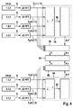
図1には、(MIMO)FMCWレーダーセンサ10の簡潔な実施例がグラフで図示されている。この実施例では、(MIMO)FMCWレーダーセンサは、第1の視界でMIMO測定を行うための2つの送信アンテナ12および4つの受信アンテナ14と、他の視界を備えた他のアンテナ15とを有している。実際には、より多くの数量のアンテナが可能である。送信アンテナ12,15は制御・評価ユニット16から給電され、対象物18によって反射されて受信アンテナ14のそれぞれによって受信されるレーダー信号を放出する。送信アンテナの15の視界は、送信アンテナ12の視界よりも、大きな検出距離と狭い視野角とを持つ。送受信アンテナはそれぞれパッチアンテナアレイから成っていてよい。
In FIG. 1, a simple example of a (MIMO)
受信信号は互いに混合されてベースバンド信号が形成され、制御・評価ユニット16内で評価される。レーダーセンサ10はたとえば自動車内の前部に組み込まれ、対象物18の、たとえば先行車両の距離d、角度、相対速度vを測定するために用いる。送信信号の周波数は、レーダー測定中に、上昇傾斜波または下降傾斜波の列を用いて変調される。
The received signals are mixed together to form a baseband signal and evaluated in the control /
単に図を見やすくするという理由だけから、ここではバイスタティックアンテナシステムが図示されている。バイスタティックアンテナシステムの場合、送信アンテナ12,15は受信アンテナ14とは異なっている。実際には、送信と受信とのためにそれぞれ同じアンテナを利用するようにしたモノスタティックアンテナコンセプトを利用してもよい。
A bistatic antenna system is illustrated here simply for the sake of clarity. In the case of the bistatic antenna system, the transmitting
アンテナ12,14は1つの方向において、すなわちレーダーセンサ10が角度分解能に優れている方向において、異なる位置に配置されている。この実施例では、受信アンテナ14は直線上に等間隔で配置されている(ULA ; Uniform Linear Array)。同様のことは送信アンテナ12に対しても適用され、この場合送受信アンテナを必ずしも同じ直線上に配置する必要はない。レーダーセンサが対象物の方位角の測定のために使用される場合には、アンテナを配置する直線は水平に延びている。これに対し、仰角を測定するためのセンサの場合には、アンテナは鉛直線上に配置される。方位角と仰角との双方を測定できる2次元アンテナアレイも考えられる。
The
図示した実施例では、レーダーセンサ10を時分割多重方法で説明する。この場合、異なる視界を持つ複数の測定が時間的に互いにインターリーブされている。各時点で、最大で、送信アンテナ12,15の1つが動作しており、送信信号を送信する。個々のアンテナ12,15の動作段階は互いに周期的に交替する。図1では、2つの送信アンテナ12のうちの下部アンテナのみが動作しているケースが図示されている。
In the illustrated embodiment, the
図2は、時間tに対してプロットした送信信号20の送信周波数fを示している。
FIG. 2 shows the transmission frequency f of the
送信アンテナ12の視界に対する測定の場合、各送信アンテナ12を用いて、時間的に互いにインターリーブされている同一の傾斜波パラメータを備えた傾斜波24,28または34,38の2つの列22,26または32,36が送信される。同じ傾斜波インデックスjを備えた傾斜波24,28は、列22,26の間にタイムオフセットT12,1,1を有している。同じ傾斜波インデックスjを備えた傾斜波34,38は、列32,36の間にタイムオフセットT12,2,1を有している。列22内では、同じ傾斜波インデックスjを備えた傾斜波24,28がタイムオフセットT12,1,1を有している。
In the case of a measurement on the field of view of the transmitting
送信アンテナ15の視界に対する測定の場合、送信アンテナ15を用いて、互いに時間的にインターリーブされている傾斜波41,43または45の3つの列40,42,44が送信される。列40,42,44の間に、傾斜波43は、同じ傾斜波インデックスjを備えた傾斜波41に対しそれぞれタイムオフセットT12,1,2を有し、傾斜波45は、それぞれタイムオフセットT13,1,2を有している。
In the case of a measurement with respect to the field of view of the transmission antenna 15, the transmission antenna 15 is used to transmit three
一般に、視界pおよび送信切換え状態mに対しては、1つの送信アンテナの選択に応じて、第1の列に対する他の列iのタイムオフセットが採用され、これを以下ではT1i,m,pと記すことにする。送信アンテナ15(p=2)に対しては常にm=1である。 In general, for view p and transmission switching state m, depending on the selection of one transmit antenna, the time offset of the other column i with respect to the first column is employed, which will be referred to as T1i, m, p in the following. I will write it down. For the transmitting antenna 15 (p = 2), m = 1 is always set.
各列内では、連続している傾斜波は互いにタイムインターバルTr2rだけシフトされている。タイムインターバルTr2rはすべての視界のすべての列に対し等しい。休止時間Pは、それぞれ1つの列の連続する2つの傾斜波の間にある。 Within each row, successive gradient waves are shifted from each other by a time interval Tr2r. The time interval Tr2r is equal for all columns of all views. The pause time P is between two consecutive ramps each in one row.
図2に示した実施例では、1つの列の内部で連続している傾斜波の傾斜波平均周波数の差は、ゼロに等しい。それ故、すべての傾斜波は同じ周波数推移を持っている。傾斜波平均周波数は、ここでは平均送信周波数f0に対応している。 In the embodiment shown in FIG. 2, the difference of the mean slope frequency of the successive slope waves within one column is equal to zero. Therefore, all the ramp waves have the same frequency transition. Ramp average frequency is here corresponds to the average transmission frequency f 0.
図4は、制御・評価ユニット16によって実施される、相対速度v、距離d、対象物角度θを特定するためのオペレーションの、詳細ブロック図である。図を簡単にするため、1つの受信チャネルnに対する処理のみが図示されており、それぞれ1つのアンテナ14に相当している。
FIG. 4 is a detailed block diagram of the operations performed by the control /
1つの視界pの1つの送信アンテナmの各列iに対し、受信されサンプリングされたベースバンド信号bi,m,pはそれぞれ2次元フーリエ変換(2D−FFT)される。第1次元は、個々の傾斜波に対し得られたベースバンド信号の変換に対応している。第2次元は、傾斜波の列に関する変換、すなわち傾斜波インデックスjに関する変換に相当している。したがって、各列iに対しては、受信チャネルn内で2次元スペクトルXi(n,m.p)が得られる。それぞれの視界に対するそれぞれの変換のサイズ、すなわちbin(サンプリング点または支持部位)のそれぞれの数量は、好ましくは、第1次元に対しすべてのスペクトルに対し一致しており、且つ第2次元に対しすべてのスペクトルに対し一致している。 The received and sampled baseband signals b i, m, p are each subjected to a two-dimensional Fourier transform (2D-FFT) for each column i of one transmit antenna m of one field of view p. The first dimension corresponds to the conversion of the baseband signal obtained for each gradient wave. The second dimension corresponds to a transformation related to a sequence of gradient waves, that is, a transformation related to the gradient wave index j. Therefore, for each column i, a two-dimensional spectrum X i (n, m.p) is obtained in the receiving channel n. The size of each transformation for each view, ie the respective quantity of bins (sampling points or support sites), is preferably consistent for all spectra for the first dimension and all for the second dimension. Is consistent with the spectrum.
レーダー目標物18の相対速度vと、個々の列に対応する部分測定の間のタイムオフセットT1i,m,pとにより、2次元スペクトルにおいて同じ位置(k,l)で発生する1つのピークX1(n,m,p)(k,l),Xi(n,m,p)(k,l)の複素振幅(スペクトル値)の間に位相差が得られる。この位相差Δφ1i,m,pはたとえば式(2)に記載されている。比較的大きなタイムオフセットT1i,m,pにより、同じ送受信アンテナを用いた2つの部分測定の間で位相差を特定しても、相対速度vをダイレクトに推定することはできない。というのは、位相の周期性のために、位相差(または、p=2の場合2つの位相差)から、相対速度vの付属値に対し多義性が生じるからである。
各視界pに対し、得られたスペクトルXi(n,m,p)から、第1の機能ブロック54において、それぞれのスペクトル値の絶対量の2乗を形成することにより、それぞれのパワースペクトルを算出する。パワースペクトルは、合算または平均化によって、1つの統合された2次元パワースペクトル56,57に点状にまとめられる。
One peak X 1 generated at the same position (k, l) in the two-dimensional spectrum due to the relative velocity v of the
For each field of view p, from the obtained spectrum X i (n, m, p), the
レーダー目標物18に対応するパワースペクトル56,57内部のピークの位置(ここではBin k,lとして記載される)は、個々のスペクトルXi(n,m,p)内でのピークの位置に対応している。ピークの位置のBin kに対応する第1次元から、FMCW方程式k=2/c(dF+f0vt)にしたがって、相対速度vとレーダー目標物の距離dとの間に線形関係が得られる。ここでcは光速、Fは傾斜波偏移、Tは個々の傾斜波の傾斜波継続時間、f0は平均送信周波数である。1つの列の連続する傾斜波の周波数差がゼロに等しければ、第2次元lにおけるピーク位置はレーダー目標物の相対速度vに関する情報だけを得る。
The position of the peak within the
図3は、相対速度vを距離dに対しプロットしたグラフである。vとdの線形関係は直線として記入されている。この例では、ドップラー周波数のサンプリングから得られる、レーダー目標物の相対速度に関する情報は、式(1)による所定のインターバルによれば多義性を伴っている。周波数bin kに従って生じるv−d直線に加えて、周波数bin lから特定される、相対速度vの周期値が、破線によって図示されている。v−d直線との交点が強調されている。これらの交点は、レーダー目標物18の相対速度と距離との可能なペア値(v,d)に対応している。速度vが特定されるはずの実際の目標物は、ばつ印Xによって強調されている。
FIG. 3 is a graph in which the relative speed v is plotted against the distance d. The linear relationship between v and d is entered as a straight line. In this example, the information regarding the relative velocity of the radar target obtained from sampling of the Doppler frequency is ambiguous according to the predetermined interval according to equation (1). In addition to the v-d line generated according to the frequency bin k, the period value of the relative velocity v specified from the frequency bin l is illustrated by a broken line. The intersection with the vd line is emphasized. These intersections correspond to possible pair values (v, d) of the relative speed and distance of the
検出された速度vの多義性は、視界pに対する多義性とは別個に、以下に説明するようにして解消される。相対速度vの、問題になっている周期値に関する情報v*を、部分測定の複素2次元スペクトルXi(n,m,p)をも含んでいる第2の機能ブロック58へ送る。
The ambiguity of the detected velocity v is resolved as described below, separately from the ambiguity for the field of view p. Information v * on the periodic value in question of the relative velocity v is sent to a second
測定された位相差を評価するため、vに依存する理想的な測定の制御ベクトルa(v)を式(3)に従って算出する。ここでは、式(3)はl=2列に対し適用される。 In order to evaluate the measured phase difference, an ideal measurement control vector a (v) depending on v is calculated according to equation (3). Here, Equation (3) is applied to l = 2 columns.
測定ベクトルak,l(n,m,p)は適当に定義されており、この場合速度に依存する予想複素値の代わりに、部分測定の2次元スペクトルのピークの位置k,lにおける複素振幅(スペクトル値)を、式(4)に記載されているようなベクトル成分として使用する。正規化は、公算関数の定義で行う。 The measurement vector a k, l (n, m, p) is well defined, in this case instead of the expected complex value depending on the speed, the complex amplitude at the peak position k, l of the two-dimensional spectrum of the partial measurement. (Spectrum value) is used as a vector component as described in equation (4). Normalization is performed by defining a probable function.
測定ベクトルと制御ベクトルとに基づいて、正規化公算関数を相対速度スペクトルS(v,p)の形で次のものとして定義する。 Based on the measurement vector and the control vector, a normalization likelihood function is defined as follows in the form of a relative velocity spectrum S (v, p).
ここでak,l H(n,m,p)は測定ベクトルak,l(n,m,p)に対するヘルメチックな随伴ベクトルであり、すなわち個々の成分がベクトルak,l(n,m,p)の成分に対し複素共役であるような行ベクトルである。したがって、公算関数は、測定ベクトルと伝送チャネルの制御ベクトルとの間の(複素)スカラー積の絶対量の2乗の正規化合算値に相当している。この場合この合算は異なる伝送チャネルを介して実施され、その際1つの伝送チャネルは受信チャネルnと送信切換え状態mのそれぞれ1つの組み合わせを意味している。 Where a k, l H (n, m, p) is a hermetic adjoint vector for the measurement vector a k, l (n, m, p), ie the individual components are the vectors a k, l (n, m , P) is a row vector that is complex conjugate. Thus, the likelihood function corresponds to the normalized sum of squares of the absolute amount of the (complex) scalar product between the measurement vector and the control vector of the transmission channel. In this case, this summation is carried out via different transmission channels, where one transmission channel means one combination of each of the reception channel n and the transmission switching state m.
相対速度スペクトルS(v,p)は、一般に、相対速度vの周期関数の重ね合わせに対応している。公算関数の最大値は、パラメータvの確率値に対応している。単独で考えると、相対速度スペクトルS(v,p)は多義的である。最大値は、vという当該値に対し得られる理想的な位相シフトが、測定ベクトルに従って測定された位相シフトと平均して最適に一致していることに対応している。しかしながら、関数S(v,p)の評価は、Bin(k,l)のピーク位置に従った評価から得られた相対速度vの周期値に対応する個所でのみ必要である。本例では、実際の相対速度がv=0m/sのときに最大限の一致が生じると仮定している。このとき関数S(v,p)は予想最大値1を占める。
The relative velocity spectrum S (v, p) generally corresponds to a superposition of periodic functions of the relative velocity v. The maximum value of the likelihood function corresponds to the probability value of the parameter v. When considered alone, the relative velocity spectrum S (v, p) is ambiguous. The maximum value corresponds to that the ideal phase shift obtained for that value of v is optimally matched on average with the phase shift measured according to the measurement vector. However, the evaluation of the function S (v, p) is necessary only at the location corresponding to the periodic value of the relative velocity v obtained from the evaluation according to the peak position of Bin (k, l). In this example, it is assumed that maximum matching occurs when the actual relative speed is v = 0 m / s. At this time, the function S (v, p) occupies the maximum expected
したがって、ピークの位置から生じる多義性は、位相関係からの付加情報によって解消することができる。線形関係に基づいて、相対速度vに対する選定判定値に属する、間隔dに対する判定値が特定される。 Therefore, the ambiguity arising from the peak position can be eliminated by the additional information from the phase relationship. Based on the linear relationship, a determination value for the interval d belonging to the selection determination value for the relative speed v is specified.
第2の機能ブロック58は、相対速度vおよび距離dに対し検出した判定値と、2つの視界pに対するピークの複素振幅Xとを角度判定器60へ出力する。たとえば、判定された相対速度vは、相対速度vによって生じる、参照列に対する個々の列のスペクトル値の位相シフトを補償するために利用することができる。
The second
したがって、傾斜波の異なる列に対応する時間信号(ベースバンド信号)は、当初別々に処理される。その後、非コヒーレント積分によって得られるパワースペクトル56でレーダー目標物18の検出を行う。その後、この検出と、ピークの位置での複素振幅とに基づいて、速度vの多義性を解消させる。
Therefore, time signals (baseband signals) corresponding to different columns of gradients are initially processed separately. Thereafter, the
好ましくは、前述したように、パワースペクトル56へのスペクトルの非コヒーレントな併合は、すべての受信チャネルおよびすべての送信チャネルに対し共通に実施される。これはピーク検出を改善させる。
Preferably, as described above, the non-coherent merging of the spectrum into the
個々のケースでは、異なる距離と異なる速度の2つのレーダー目標物がスペクトル56,57に同じピーク位置(k,l)を占めることがある。この場合、測定した位相関係を1つのレーダー目標物の1つの相対速度に割り当てることはできない。評価装置16は、閾値を越えるほどに最大一致がずれたことに基づき、すなわち相対速度スペクトルS(v,p)の極大値が予想される極大値1からずれたことに基づき、測定のこのような障害を検知するように設置されていてよい。このとき、評価装置16は障害信号を出力することができる。しかしながら、スペクトル56,57で主に発生するピークの多重占有は、レーダー目標物18のvとdの判定値に基づいて実施される、検出された対象物のトラッキングの際に、評価装置16が複数の測定周期にわたって誤検出を検知することにも認められる。
In individual cases, two radar targets with different distances and different velocities may occupy the same peak position (k, l) in the
好ましくは、互いに連続して実施される複数のレーダー測定に対し、傾斜波の異なる変調パラメータを使用する。たとえば異なる平均周波数、傾斜波勾配、タイムインターバルTr2rおよび/またはタイムオフセットT1i,m,pを使用する。これによって、不意のピーク位置多重占有を個々のケースで制限することができる。 Preferably, different modulation parameters of the ramp are used for a plurality of radar measurements performed in succession to each other. For example, different average frequencies, slope gradients, time intervals Tr2r and / or time offsets T1i, m, p are used. As a result, unintended peak position multiplex occupation can be limited in individual cases.
個々のスペクトルをパワースペクトル56または57に非コヒーレントに併合する代わりに、複数の受信チャネルnを、デジタルビーム形成(beam forming)により1つの受信チャネルに統合することが考えられる。その際、たとえばそれぞれの視角pおよび場合によっては送信切換え状態mに対して、N個の受信チャネルのスペクトルまたは測定ベクトルがコヒーレントになり、すなわち位相を考慮して、それぞれの速度因子と合算する。この場合、対応的に、S(v,p)に対する関係において、nに関する加算は省略する。
Instead of merging individual spectra into the
ベースバンド信号のスペクトルXに加えて、または、これの代わりに、ベースバンド信号bをダイレクトに角度判定器60へ出力させるか、或いは、ベースバンド信号bから別個に算出したスペクトルを角度判定器へ出力させてもよい。
In addition to or instead of the spectrum X of the baseband signal, the baseband signal b is directly output to the
12,15 送信アンテナ
18 レーダー目標物
20 送信信号
22,26,32,36,40,42,44 傾斜波の列
24,28,34,38,41,43,45 傾斜波
56 ベースバンド信号のスペクトル
a(v,m,p) 位相関係
b ベースバンド信号
j 傾斜波インデックス
k,l 2次元スペクトルでの位置
p 視界
T12,1;T12,2 タイムオフセット
Tr2r タイムインターバル
v 相対速度
X 2次元スペクトル
12, 15 Transmitting
Claims (12)
ステップ(a):異なる視界(p)に対する測定サイクルで、傾斜状に周波数変調された送信信号(20)を送信するような測定をそれぞれ実施し、前記送信信号の変調モードが、複数の傾斜波(24;28;34;38;41;43;45)の列(22;26;32;36;40;42;44)を含み、該列(22;26;32;36;40;42;44)は時間的に互いにインターリーブされており、前記傾斜波がそれぞれの前記列内でタイムインターバル(Tr2r)で時間的に互いにずれて繰り返されており、
異なる視界(p)による測定列が、時間的に互いにインターリーブされており、その際視界(p)間での規則的なパターンで交替し、
複数の視界(p)のうちの少なくとも1つの視界に対し、測定が変調パターンを有し、該変調パターンが、それぞれの列内での傾斜波を数え上げる同じ傾斜波インデックス(j)を備えた異なる前記列(22,26;32,36)の前記傾斜波(24,28;34,38)の間で規則的に反復する少なくとも2つの異なるタイムオフセット(T12,1;T12,2)をそれぞれの前記列内に有し、これらタイムオフセット(T12,1;T12,2)は、それぞれ1つの列内で前記傾斜波が繰り返されている前記タイムインターバル(Tr2r)とは異なっていること、
ステップ(b):前記ベースバンド信号(b)から、前記列(22;26;32;36;40;42;44)のそれぞれとは別個に、2次元フーリエ変換により、2次元スペクトル(X)を算出し、第1次元で傾斜波ごとに変換を行い、第2次元で前記傾斜波インデックス(j)を介して変換を行うこと、
ステップ(c):複数の視界(p)のうちの少なくとも1つの視界に対し、それぞれの視界の前記ベースバンド信号(b)の少なくとも1つの2次元スペクトル(56)のピークの位置(k,l)を用いて、それぞれの視界内で検出した、所定の速度周期とともに周期的であるような、レーダー対象物(18)の相対速度(v)に対する値を特定すること、
ステップ(d):複数の視界(p)のうちの少なくとも1つの視界に対し、該視界(p)の別個に算出した前記2次元スペクトル(X)内でのそれぞれ同じ位置(k,l)で得られるスペクトル値間の少なくとも1つの位相関係が、検出された前記レーダー対象物(18)の前記相対速度(v)の特定された複数の周期値に対し予想される位相関係(a(v,m,p))と一致しているかどうかをチェックすること、
ステップ(e):複数の視界(p)のうちの少なくとも1つの視界に対し、前記相対速度(v)の特定された前記複数の周期値から、前記チェックの結果に基づいて、それぞれの視界内で検出した前記レーダー対象物(18)の前記相対速度(v)に対する判定値を選定すること。 FMCW radar measurements are performed using a transmitting antenna (12; 15) with different views (p) that differ in view angle and / or detection distance, and the received signals are mixed to form a baseband signal ( a method for determining the position of a radar object (18) adapted to form b) comprising the following steps (a) to (e):
Step (a): different vision measurement cycle for (p), inclined to the frequency-modulated transmission signal measurements such as to transmit the (20) carried respectively, modulation mode of the transmission signal is, the slope of multiple includes (44 22; 26; 32; 36; 40; 42), said column (22; wave (24; 28; 34; 38; 41; 43 45) column in 26; 32; 36; 40; 42 44) are interleaved with each other in time, and the ramps are repeated with a time interval (Tr2r) shifted in time in each of the columns,
Measurement columns with different fields of view (p) are interleaved with each other in time, with alternating regular patterns between fields of view (p),
For at least one view of the plurality of views (p), the measurement has a modulation pattern, the modulation pattern being different with the same ramp index (j) counting the ramps in each column At least two different time offsets (T12,1; T12,2) that regularly repeat between the ramps (24,28; 34,38) of the row (22,26; 32,36) are The time offsets (T12,1; T12,2) in the column are different from the time interval (Tr2r) in which the ramp wave is repeated in one column,
Step (b) : Two-dimensional spectrum (X) from the baseband signal (b) by two-dimensional Fourier transform separately from each of the columns (22; 26; 32; 36; 40; 42; 44). Calculating for each ramp wave in the first dimension and transforming via the ramp index (j) in the second dimension;
Step (c) : For at least one view of the plurality of views (p), the peak position (k, l) of at least one two-dimensional spectrum (56) of the baseband signal (b) of each view. ) To identify a value for the relative velocity (v) of the radar object (18) that is detected in each field of view and is periodic with a predetermined velocity period;
Step (d) : For at least one of the plurality of views (p), at the same position (k, l) in the two-dimensional spectrum (X) calculated separately for the view (p). At least one phase relationship between the resulting spectral values is expected for a plurality of identified period values of the relative velocity (v) of the detected radar object (18) (a (v, m, p)) to check if it matches,
Step (e) : For at least one view of the plurality of views (p), from the plurality of periodic values specified for the relative velocity (v), based on the result of the check, Selecting a judgment value for the relative speed (v) of the radar object (18) detected in (1) .
前記3つの列が、第1の列(40)に関し、それぞれ他の列(42;44)に割り当てられる異なるタイムオフセット(T12,m,p;T13,m,p)を互いに有している、請求項1に記載の方法。 For at least one field of view (p), the measurement has a modulation pattern, the modulation pattern comprising at least three columns (40; 42; 44) of said columns, wherein these columns On the other hand, the same antenna (15) is used for transmission,
The three columns have different time offsets (T12, m, p; T13, m, p) with respect to the first column (40), respectively, assigned to the other columns (42; 44), respectively. The method of claim 1.
これら送信切換え状態(m)にそれぞれ少なくとも2つの前記列(22;26;32;36)が割り当てられ、これらの列が、時間的に互いにインターリーブされており、且つ第1の列(22;32)に関し、それぞれ他の列(26;36)に割り当てられるタイムオフセット(T12,m,p)を互いに有し、
これら異なる送信切換え状態(m)において、前記他の列(26;36)に異なるタイムオフセット(T12,1,p,T12,2,p)が割り当てられ、
異なる前記送信切換え状態(m)が割り当てられている、前記測定の互いに連続する前記傾斜波(24;28;34;38)の間にして、当該送信切換え状態(m)の間で切換えを行う、
請求項1または2に記載の方法。 Measurement is performed using a plurality of antennas (12) used for transmission with respect to at least one field of view (p), and the antenna (12) used for transmission at that time Using at least two different transmission switching states (m) that are different with respect to the selection of
Each of these transmission switching states (m) is assigned at least two said columns (22; 26; 32; 36), these columns are interleaved in time and the first column (22; 32). ) Each having a time offset (T12, m, p) assigned to the other columns (26; 36), respectively.
In these different transmission switching states (m), different time offsets (T12, 1, p, T12, 2, p) are assigned to the other columns (26; 36),
Switching between the transmission switching states (m) is performed between the successive ramps (24; 28; 34; 38) of the measurement, to which the different transmission switching states (m) are assigned. ,
The method according to claim 1 or 2.
複数の前記視界(p)で位置決定されたレーダー目標物(18)の角度位置(θ)を、送信および/または受信に使用する前記アンテナ(12,15;14)の異なる選定に対し得られる前記複数の視界(p)の測定の前記ベースバンド信号(b)の2次元スペクトル(X)において前記レーダー目標物(18)に対応するピークの位置(k,l)での振幅および/または位相に基づいて特定する、請求項1から3のいずれか一つに記載の方法。 For at least two views of the plurality of views (p), each measurement is an angular resolution measurement, which is used to transmit and / or receive a plurality of antennas (12, 15; 14). ) With different selections,
The angular position (θ) of a radar target (18) located in a plurality of the fields of view (p) is obtained for different selections of the antennas (12, 15; 14) used for transmission and / or reception. The amplitude and / or phase at the position (k, l) of the peak corresponding to the radar target (18) in the two-dimensional spectrum (X) of the baseband signal (b) of the plurality of fields of view (p) measurements. The method according to claim 1, wherein the method is specified based on:
レーダー目標物(18)の位置を決定するため、それぞれの視界(p)の測定の前記ベースバンド信号(b)の2次元スペクトル(56;57)においてピークを求め、
それぞれの視界(p)で位置決定されるレーダー目標物(18)の角度位置(θ)を、前記ベースバンド信号(b)の2次元スペクトル(X)で前記レーダー目標物(18)に対応するピークの位置(k.l)での振幅および/または位相に基づいて特定し、前記ベースバンド信号が送信および/または受信に使用する前記アンテナ(12,15;14)の異なる選定に対し得られるようにした、請求項1から4のいずれか一つに記載の方法において、
前記複数の視界(p)のうちの少なくとも1つの視界において、その距離(d)および/またはその角度位置(θ)が当該視界(p)と前記レーダー目標物(18)の位置が決定されなかった他の視界(p)とのオーバーラップ領域にあるような位置(d,θ)で、1つのレーダー目標物(18)の位置が決定された場合、前記他の視界(p)の測定の前記ベースバンド信号の2次元スペクトル(X)において前記レーダー目標物(18)に対応する位置(k,l)での振幅および/または位相を補助的に関連付けて、前記角度位置(θ)の特定または修正を行う方法。 For at least two views of the plurality of views (p), each measurement is an angular resolution measurement, which is used to transmit and / or receive a plurality of antennas (12, 15; 14). ) With different selections,
In order to determine the position of the radar target (18), a peak is determined in the two-dimensional spectrum (56; 57) of the baseband signal (b) for each field of view (p) measurement;
The angular position (θ) of the radar target (18) determined in each field of view (p) corresponds to the radar target (18) in the two-dimensional spectrum (X) of the baseband signal (b). Based on the amplitude and / or phase at the peak position (kl), the baseband signal is obtained for different selections of the antennas (12, 15; 14) used for transmission and / or reception The method according to any one of claims 1 to 4, wherein
In at least one view of the plurality of views (p), the distance (d) and / or the angular position (θ) is not determined as the position of the view (p) and the radar target (18). If the position of one radar target (18) is determined at a position (d, θ) that is in an overlap region with another field of view (p), the measurement of the other field of view (p) In the two-dimensional spectrum (X) of the baseband signal, the angular position (θ) is identified by supplementally associating the amplitude and / or phase at the position (k, l) corresponding to the radar target (18). Or how to make corrections.
前記傾斜波平均周波数の前記差がゼロでなく、
測定のそれぞれの前記列(22;26;32;36;40;42;44)内で同じ前記傾斜波インデックス(j)を持つ傾斜波(24;28;34;38;41;43;45)が、同じ前記傾斜波勾配(F/T)と同じ前記傾斜波平均周波数とを有している、請求項1から5のいずれか一つに記載の方法。 The gradient waves (24; 28; 34; 38; 41; 43; 45) that are continuous in each row (22; 26; 32; 36; 40; 42; 44) are the same gradient (F / T And having the same difference in the mean slope frequency,
Not the difference Gaze b of the ramp mean frequency,
Ramp waves (24; 28; 34; 38; 41; 43; 45) with the same ramp index (j) in each said row of measurements (22; 26; 32; 36; 40; 42; 44) 6. The method according to any one of claims 1 to 5, wherein the same gradient wave gradient (F / T) and the same gradient wave average frequency.
Applications Claiming Priority (3)
| Application Number | Priority Date | Filing Date | Title |
|---|---|---|---|
| DE102014212281.3A DE102014212281A1 (en) | 2014-06-26 | 2014-06-26 | Radar measurement with different viewing areas |
| DE102014212281.3 | 2014-06-26 | ||
| PCT/EP2015/058753 WO2015197223A1 (en) | 2014-06-26 | 2015-04-23 | Radar measurement method with different fields of view |
Publications (3)
| Publication Number | Publication Date |
|---|---|
| JP2017522575A JP2017522575A (en) | 2017-08-10 |
| JP2017522575A5 JP2017522575A5 (en) | 2018-07-12 |
| JP6372965B2 true JP6372965B2 (en) | 2018-08-15 |
Family
ID=52997446
Family Applications (1)
| Application Number | Title | Priority Date | Filing Date |
|---|---|---|---|
| JP2017518412A Active JP6372965B2 (en) | 2014-06-26 | 2015-04-23 | Radar measurement method using multiple different fields of view |
Country Status (6)
| Country | Link |
|---|---|
| US (1) | US10557931B2 (en) |
| EP (1) | EP3161513B1 (en) |
| JP (1) | JP6372965B2 (en) |
| CN (1) | CN107076835B (en) |
| DE (1) | DE102014212281A1 (en) |
| WO (1) | WO2015197223A1 (en) |
Families Citing this family (22)
| Publication number | Priority date | Publication date | Assignee | Title |
|---|---|---|---|---|
| EP3121619A1 (en) * | 2015-07-22 | 2017-01-25 | Nxp B.V. | A radar system |
| DE102016100217A1 (en) * | 2016-01-06 | 2017-07-06 | Hella Kgaa Hueck & Co. | radar sensor |
| CN109791198B (en) | 2016-08-15 | 2023-08-15 | 代表亚利桑那大学的亚利桑那校董会 | Novel automotive radar using 3D printed luneberg lenses |
| US10473757B2 (en) * | 2016-12-19 | 2019-11-12 | Honeywell International Inc. | Moving target identification without special radar mode |
| DE102017200317A1 (en) | 2017-01-11 | 2018-07-12 | Robert Bosch Gmbh | Radar sensor and method for determining a relative speed of a radar target |
| EP3410150B1 (en) * | 2017-05-30 | 2022-01-19 | Nxp B.V. | Apparatus for detection and ranging |
| DE102017120368A1 (en) * | 2017-09-05 | 2019-03-07 | HELLA GmbH & Co. KGaA | Method and apparatus for generating a modulated continuous wave radar signal |
| JP6923799B2 (en) * | 2017-09-29 | 2021-08-25 | ミツミ電機株式会社 | Radar device |
| DE102018200765A1 (en) * | 2018-01-18 | 2019-07-18 | Robert Bosch Gmbh | FMCW radar sensor |
| DE102018200752A1 (en) * | 2018-01-18 | 2019-07-18 | Robert Bosch Gmbh | Method and device for evaluating an angular position of an object, and driver assistance system |
| DE102018210083A1 (en) | 2018-06-21 | 2019-12-24 | Robert Bosch Gmbh | Evaluation device and method for evaluating at least one radar sensor |
| KR102628655B1 (en) * | 2018-06-29 | 2024-01-24 | 삼성전자주식회사 | Method and device to operate radar |
| DE102018121987A1 (en) | 2018-09-10 | 2020-03-12 | Infineon Technologies Ag | Frequency modulated continuous wave radar system |
| US11092686B2 (en) * | 2018-09-19 | 2021-08-17 | Steradian Semiconductors Private Limited | Method, apparatus and device for doppler compensation in a time switched MIMO radar system |
| DE102018124582A1 (en) * | 2018-10-05 | 2020-04-09 | HELLA GmbH & Co. KGaA | Procedure for detection in a radar system |
| US11309636B2 (en) * | 2019-12-18 | 2022-04-19 | Waymo Llc | Antenna structure for reducing beam squint and sidelobes |
| DE102020107222A1 (en) * | 2020-03-17 | 2021-09-23 | HELLA GmbH & Co. KGaA | Method for determining direction information |
| US20210364599A1 (en) * | 2020-05-20 | 2021-11-25 | Infineon Technologies Ag | Radar receiving system and method for compensating a phase error between radar receiving circuits |
| EP3923023A3 (en) * | 2020-05-20 | 2022-03-09 | Infineon Technologies AG | Processing radar signals |
| CN112147587B (en) * | 2020-09-28 | 2022-02-25 | 中国电波传播研究所(中国电子科技集团公司第二十二研究所) | Radar beam azimuth center offshore calibration method |
| EP4012443A1 (en) * | 2020-12-08 | 2022-06-15 | Veoneer Sweden AB | A vehicle radar system |
| KR20220168380A (en) * | 2021-06-16 | 2022-12-23 | 삼성전자주식회사 | Antenna module and electronic device including the same, and method of operating the same |
Family Cites Families (20)
| Publication number | Priority date | Publication date | Assignee | Title |
|---|---|---|---|---|
| JP2768439B2 (en) | 1994-11-08 | 1998-06-25 | 本田技研工業株式会社 | FM-CW type multi-beam radar device |
| ATE202635T1 (en) * | 1995-03-03 | 2001-07-15 | Siemens Ag | METHOD AND ARRANGEMENT FOR TRAFFIC DETECTION USING A RADAR DEVICE |
| US6577269B2 (en) * | 2000-08-16 | 2003-06-10 | Raytheon Company | Radar detection method and apparatus |
| CN1150407C (en) * | 2000-09-29 | 2004-05-19 | 清华大学 | Time division multiplexing channel antenna array system and signal processing method thereof |
| US6606052B1 (en) * | 2002-03-07 | 2003-08-12 | Visteon Global Technologies, Inc. | Method and apparatus for detecting multiple objects with frequency modulated continuous wave radar |
| DE102004059915A1 (en) | 2004-12-13 | 2006-06-14 | Robert Bosch Gmbh | radar system |
| DE102005012945A1 (en) * | 2005-03-21 | 2006-09-28 | Robert Bosch Gmbh | Method and apparatus for distance and relative velocity measurement of multiple objects |
| WO2008053685A1 (en) * | 2006-11-01 | 2008-05-08 | Murata Manufacturing Co., Ltd. | Radar target detecting method and radar device using the target detection method |
| JP2009288223A (en) * | 2008-06-02 | 2009-12-10 | Mitsubishi Electric Corp | Radar device |
| WO2010115418A2 (en) * | 2009-04-06 | 2010-10-14 | Conti Temic Microelectronic Gmbh | Radar system having arrangements and method for decoupling transmission and reception signals and suppression of interference radiation |
| JP5468304B2 (en) * | 2009-05-20 | 2014-04-09 | 株式会社東芝 | Radar equipment |
| DE102010030289A1 (en) * | 2010-06-21 | 2011-12-22 | Robert Bosch Gmbh | Radar sensor and method for operating a radar sensor |
| US8902103B2 (en) * | 2011-03-16 | 2014-12-02 | Electronics And Telecommunications Research Institute | Radar apparatus supporting short and long range radar operation |
| DE102012008350A1 (en) * | 2012-04-19 | 2013-10-24 | S.M.S Smart Microwave Sensors Gmbh | Method and device for tuning the distance and radial velocity of an object by means of radar signals |
| ITTO20120417A1 (en) * | 2012-05-09 | 2013-11-10 | St Microelectronics Srl | PROCEDURE AND DEVICES FOR DEVELOPING RADAR SIGNALS, FOR EXAMPLE FOR ROAD SAFETY SYSTEMS, ITS RELATED PRODUCT |
| DE102012212888A1 (en) * | 2012-07-23 | 2014-01-23 | Robert Bosch Gmbh | Detection of radar objects with a radar sensor of a motor vehicle |
| DE102012220879A1 (en) * | 2012-11-15 | 2014-05-15 | Robert Bosch Gmbh | Rapid-chirp-FMCW radar |
| TWI472790B (en) * | 2013-05-31 | 2015-02-11 | Wistron Neweb Corp | Signal generating method and radar system |
| DE102013210256A1 (en) * | 2013-06-03 | 2014-12-04 | Robert Bosch Gmbh | INTERFERENCE SUPPRESSION ON AN FMCW RADAR |
| DE102014104273A1 (en) * | 2014-03-26 | 2015-10-01 | Friedrich-Alexander-Universität Erlangen-Nürnberg | Method in a radar system, radar system or apparatus of a radar system |
-
2014
- 2014-06-26 DE DE102014212281.3A patent/DE102014212281A1/en not_active Withdrawn
-
2015
- 2015-04-23 CN CN201580034470.2A patent/CN107076835B/en active Active
- 2015-04-23 EP EP15717897.1A patent/EP3161513B1/en active Active
- 2015-04-23 US US15/319,417 patent/US10557931B2/en active Active
- 2015-04-23 WO PCT/EP2015/058753 patent/WO2015197223A1/en active Application Filing
- 2015-04-23 JP JP2017518412A patent/JP6372965B2/en active Active
Also Published As
| Publication number | Publication date |
|---|---|
| JP2017522575A (en) | 2017-08-10 |
| CN107076835B (en) | 2020-09-22 |
| CN107076835A (en) | 2017-08-18 |
| US20170131393A1 (en) | 2017-05-11 |
| US10557931B2 (en) | 2020-02-11 |
| EP3161513A1 (en) | 2017-05-03 |
| DE102014212281A1 (en) | 2015-12-31 |
| WO2015197223A1 (en) | 2015-12-30 |
| EP3161513B1 (en) | 2020-10-28 |
Similar Documents
| Publication | Publication Date | Title |
|---|---|---|
| JP6372965B2 (en) | Radar measurement method using multiple different fields of view | |
| JP6533288B2 (en) | MIMO radar measurement method | |
| JP6334822B2 (en) | Radar measurement method | |
| JP6368801B2 (en) | Method for locating an object with an FMCW radar | |
| KR102336927B1 (en) | Method and radar sensor for determining the relative velocity of a radar target | |
| US10012726B2 (en) | Rapid-chirps-FMCW radar | |
| US9547078B2 (en) | Detection of radar objects using a radar sensor of a motor vehicle | |
| US9354304B2 (en) | Method for cyclically measuring distances and velocities of objects using an FMCW radar sensor | |
| KR101757949B1 (en) | Method for unambiguously determining a range and/or a relative speed of an object, driver assistance device and motor vehicle | |
| CN108333581B (en) | Multi-undersampled chirp sequence radar | |
| US9983294B2 (en) | Radar system | |
| JP2017522575A5 (en) | ||
| CN102356332A (en) | Radar system having arrangements and method for decoupling transmission and reception signals and suppression of interference radiation | |
| JP2020509390A (en) | Method and apparatus for calculating a lateral relative velocity component of a radar target | |
| US20210278522A1 (en) | Radar device | |
| JP2021513657A (en) | Angle-resolved, wideband radar sensor for automobiles | |
| JP7019059B2 (en) | Estimating lateral speed or Cartesian speed of point target by radar sensor | |
| JP2013238414A (en) | On-vehicle radar device, azimuth detection method, and azimuth detection program | |
| KR100643939B1 (en) | Radar and distance measuring method thereof | |
| JP2021514061A (en) | Estimating the Cartesian velocity of an extended radar object with a radar sensor | |
| KR20230081654A (en) | Radar measurement method | |
| CN114594466A (en) | Method for determining an own velocity estimate and an angle estimate of a target |
Legal Events
| Date | Code | Title | Description |
|---|---|---|---|
| A977 | Report on retrieval |
Free format text: JAPANESE INTERMEDIATE CODE: A971007 Effective date: 20171128 |
|
| A131 | Notification of reasons for refusal |
Free format text: JAPANESE INTERMEDIATE CODE: A131 Effective date: 20171215 |
|
| A601 | Written request for extension of time |
Free format text: JAPANESE INTERMEDIATE CODE: A601 Effective date: 20180307 |
|
| A524 | Written submission of copy of amendment under article 19 pct |
Free format text: JAPANESE INTERMEDIATE CODE: A524 Effective date: 20180530 |
|
| TRDD | Decision of grant or rejection written | ||
| A01 | Written decision to grant a patent or to grant a registration (utility model) |
Free format text: JAPANESE INTERMEDIATE CODE: A01 Effective date: 20180622 |
|
| A61 | First payment of annual fees (during grant procedure) |
Free format text: JAPANESE INTERMEDIATE CODE: A61 Effective date: 20180716 |
|
| R150 | Certificate of patent or registration of utility model |
Ref document number: 6372965 Country of ref document: JP Free format text: JAPANESE INTERMEDIATE CODE: R150 |
|
| R250 | Receipt of annual fees |
Free format text: JAPANESE INTERMEDIATE CODE: R250 |
|
| R250 | Receipt of annual fees |
Free format text: JAPANESE INTERMEDIATE CODE: R250 |
|
| R250 | Receipt of annual fees |
Free format text: JAPANESE INTERMEDIATE CODE: R250 |