JP6371167B2 - Reverberation suppression device - Google Patents
Reverberation suppression device Download PDFInfo
- Publication number
- JP6371167B2 JP6371167B2 JP2014179656A JP2014179656A JP6371167B2 JP 6371167 B2 JP6371167 B2 JP 6371167B2 JP 2014179656 A JP2014179656 A JP 2014179656A JP 2014179656 A JP2014179656 A JP 2014179656A JP 6371167 B2 JP6371167 B2 JP 6371167B2
- Authority
- JP
- Japan
- Prior art keywords
- gain
- instantaneous value
- reverberation
- component
- estimated
- Prior art date
- Legal status (The legal status is an assumption and is not a legal conclusion. Google has not performed a legal analysis and makes no representation as to the accuracy of the status listed.)
- Active
Links
Images
Classifications
-
- G—PHYSICS
- G10—MUSICAL INSTRUMENTS; ACOUSTICS
- G10L—SPEECH ANALYSIS OR SYNTHESIS; SPEECH RECOGNITION; SPEECH OR VOICE PROCESSING; SPEECH OR AUDIO CODING OR DECODING
- G10L21/00—Processing of the speech or voice signal to produce another audible or non-audible signal, e.g. visual or tactile, in order to modify its quality or its intelligibility
- G10L21/02—Speech enhancement, e.g. noise reduction or echo cancellation
- G10L21/0316—Speech enhancement, e.g. noise reduction or echo cancellation by changing the amplitude
- G10L21/0324—Details of processing therefor
- G10L21/034—Automatic adjustment
-
- G—PHYSICS
- G10—MUSICAL INSTRUMENTS; ACOUSTICS
- G10L—SPEECH ANALYSIS OR SYNTHESIS; SPEECH RECOGNITION; SPEECH OR VOICE PROCESSING; SPEECH OR AUDIO CODING OR DECODING
- G10L21/00—Processing of the speech or voice signal to produce another audible or non-audible signal, e.g. visual or tactile, in order to modify its quality or its intelligibility
- G10L21/02—Speech enhancement, e.g. noise reduction or echo cancellation
- G10L21/0208—Noise filtering
-
- H—ELECTRICITY
- H04—ELECTRIC COMMUNICATION TECHNIQUE
- H04R—LOUDSPEAKERS, MICROPHONES, GRAMOPHONE PICK-UPS OR LIKE ACOUSTIC ELECTROMECHANICAL TRANSDUCERS; DEAF-AID SETS; PUBLIC ADDRESS SYSTEMS
- H04R3/00—Circuits for transducers, loudspeakers or microphones
-
- G—PHYSICS
- G10—MUSICAL INSTRUMENTS; ACOUSTICS
- G10L—SPEECH ANALYSIS OR SYNTHESIS; SPEECH RECOGNITION; SPEECH OR VOICE PROCESSING; SPEECH OR AUDIO CODING OR DECODING
- G10L21/00—Processing of the speech or voice signal to produce another audible or non-audible signal, e.g. visual or tactile, in order to modify its quality or its intelligibility
- G10L21/02—Speech enhancement, e.g. noise reduction or echo cancellation
- G10L21/0208—Noise filtering
- G10L2021/02082—Noise filtering the noise being echo, reverberation of the speech
Description
本発明は、残響抑制装置に関するものである。 The present invention relates to a reverberation suppression device.
音響信号から残響を除去する技術が種々提案されている。ある技術では、最初に音響信号を採取し、採取した音響信号に基づいて逆フィルタを作成し、そして、作成した逆フィルタを使用して、音響信号から残響を除去している(例えば特許文献1,2参照)。 Various techniques for removing reverberation from an acoustic signal have been proposed. In one technique, an acoustic signal is first collected, an inverse filter is created based on the collected acoustic signal, and reverberation is removed from the acoustic signal using the created inverse filter (for example, Patent Document 1). , 2).
しかしながら、上述の技術では、室内などの環境による残響の評価(つまり、逆フィルタの作成)を事前に行う必要があり、残響の評価を正確に行おうとすると、時間を要してしまう。また、残響の評価に要する時間を短くすると、逆フィルタの誤差が大きくなり、音質が劣化する可能性がある。さらに、逆フィルタを作成する場合、演算量が大きくなるため、所要時間を短くするためには、装置の処理速度を高くする必要があり、装置のコストが高くなってしまう。 However, in the above-described technique, it is necessary to perform evaluation of reverberation (that is, creation of an inverse filter) in advance in an environment such as a room, and it takes time to accurately evaluate reverberation. Moreover, if the time required for the evaluation of reverberation is shortened, the error of the inverse filter increases and the sound quality may be deteriorated. Furthermore, when an inverse filter is created, the amount of calculation increases, so in order to shorten the required time, it is necessary to increase the processing speed of the apparatus, which increases the cost of the apparatus.
本発明は、上記の問題に鑑みてなされたものであり、比較的簡単な演算で残響を抑制する残響抑制装置を得ることを目的とする。 The present invention has been made in view of the above problems, and an object thereof is to obtain a reverberation suppressing device that suppresses reverberation with a relatively simple calculation.
本発明に係る残響抑制装置は、入力信号の絶対値または2乗に相関がある値のエンベロープにおける瞬時値を算出する瞬時値算出部と、瞬時値算出部により算出される瞬時値の指数移動平均を推定残響成分として算出する残響推定部と、瞬時値が推定残響成分より大きい期間においては、推定残響成分および瞬時値に基づいて入力信号に対するゲインを導出し、瞬時値が推定残響成分より小さい期間においては、ゲインを下限値にするゲイン導出部と、ゲイン導出部により導出されたゲインに対してスムージング処理を行うスムージング処理部と、スムージング処理後のゲインを入力信号の振幅調整に適用するゲイン処理部とを備える。 An dereverberation apparatus according to the present invention includes an instantaneous value calculation unit that calculates an instantaneous value in an envelope having a value correlated with an absolute value or a square of an input signal, and an exponential moving average of instantaneous values calculated by the instantaneous value calculation unit Reverberation estimator that computes the estimated reverberation component, and in the period when the instantaneous value is greater than the estimated reverberation component, the gain for the input signal is derived based on the estimated reverberation component and the instantaneous value, , A gain deriving unit that sets the gain to a lower limit value, a smoothing processing unit that performs a smoothing process on the gain derived by the gain deriving unit, and a gain process that applies the gain after the smoothing process to the amplitude adjustment of the input signal A part.
本発明によれば、比較的簡単な演算で残響が抑制される。 According to the present invention, reverberation is suppressed by a relatively simple calculation.
以下、図に基づいて本発明の実施の形態を説明する。 Hereinafter, embodiments of the present invention will be described with reference to the drawings.
実施の形態1.
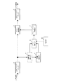
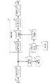
図1は、本発明の実施の形態1に係る残響抑制装置の構成を示すブロック図である。図1に示す残響抑制装置は、分析フィルタバンク1、ゲイン処理部2、合成フィルタバンク3、瞬時値算出部4、残響推定部5、ゲイン導出部6、スムージング処理部7、および設定部8を備える。例えば、この装置の各部は、デジタルシグナルプロセッサ(DSP)として実現してもよいし、コンピュータでプログラムを実行することで実現してもよい。
FIG. 1 is a block diagram showing a configuration of a reverberation suppression apparatus according to
分析フィルタバンク1は、入力信号(音響信号)を所定の複数(例えば32)の周波数帯域の成分に分割する。入力信号には音声が含まれている。
The
ゲイン処理部2は、分析フィルタバンク1による分割で得られた所定数の周波数帯域の成分に対してゲインをそれぞれ適用する。その際、ゲイン処理部2は、スムージング処理部7によるスムージング処理後のゲインを入力信号(つまり、各周波数帯域の成分)の振幅調整に適用する。
The
合成フィルタバンク3は、ゲイン処理部2によりゲインを適用された所定数の周波数帯域の成分を合成して出力信号を生成する。
The
瞬時値算出部4は、入力信号の絶対値または2乗に相関がある値のエンベロープにおける瞬時値を算出する。この実施の形態では、瞬時値算出部4は、入力信号の2乗に相関がある値としてのパワーのエンベロープ(時間包絡)における瞬時値を算出する。ただし、この瞬時値として、入力信号の絶対値を使用してもよい。なお、ここでは、入力信号における上述の所定数の周波数帯域の成分のそれぞれについて瞬時値が算出される。
The instantaneous
残響推定部5は、瞬時値算出部4により算出される瞬時値の指数移動平均を推定残響成分として算出する。ここでは、入力信号における上述の所定数の周波数帯域の成分のそれぞれについて推定残響成分が算出される。例えば、残響推定部5は、各時点の瞬時値を、その時点から所定の期間だけ保持し、各時点で保持している瞬時値に基づいてその時点の指数移動平均を計算する。
The
なお、指数移動平均は、加重移動平均の一種で、加重係数を指数関数的に減衰させていくものである。残響推定部5は、指数移動平均の加重係数を、推定残響成分が瞬時値より小さい期間においては第1時定数で減衰させていき、推定残響成分が瞬時値より大きい期間においては、第1時定数より小さい第2時定数で減衰させていく。
The exponential moving average is a kind of weighted moving average, which attenuates the weighting coefficient exponentially. The
ゲイン導出部6は、上述の推定残響成分および上述の瞬時値に基づいて入力信号に対するゲインを導出する。その際、ゲイン導出部6は、推定残響成分が瞬時値より大きい期間においてはゲインを下限値にする。ここでは、入力信号における上述の所定数の周波数帯域の成分のそれぞれについてゲインが導出される。
The gain deriving
この実施の形態では、ゲイン導出部6は、推定残響成分が瞬時値より小さい期間においては所定の特性で推定残響成分および瞬時値に応じてゲインを変化させ、推定残響成分が瞬時値より大きい期間においてはゲインを所定値(以下、ゲイン下限値という)に固定する。
In this embodiment, the
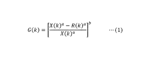
ここでは、上述の特性は、所定の計算式に基づくものである。図2は、図1におけるゲイン導出部6によるゲインの導出に使用される計算式の一例を示す図である。図2に示す計算式(1)は、第kの周波数帯域についてのゲインG(k)を導出するための式であり、aを第1指数としbを第2指数としたとき、瞬時値X(k)のa乗と推定残響成分R(k)のa乗との差を瞬時値X(k)のa乗で除算したもののb乗をゲインG(k)としている。計算式(1)のゲインG(k)は、音声等の変動がある音については、その変動に応じたゲインを与え、定常的なノイズ音については、ゲインを小さくするように動作する。また、上述の特性では、この計算式の値が上述のゲイン下限値以上である場合には、ゲイン導出部6は、この計算式の値をゲインの値とし、この計算式の値が上述のゲイン下限値未満となる場合には、ゲイン下限値をゲインの値として、ゲインG1(k)を出力する。
Here, the above-described characteristics are based on a predetermined calculation formula. FIG. 2 is a diagram illustrating an example of a calculation formula used for gain derivation by the
例えば、瞬時値が入力信号(つまり、第kの周波数帯域の成分)のパワー値である場合、a=1,b=1/2とし、瞬時値が入力信号(つまり、第kの周波数帯域の成分)の絶対値である場合、a=2,b=1/2とする。 For example, when the instantaneous value is the power value of the input signal (that is, the component in the kth frequency band), a = 1 and b = 1/2, and the instantaneous value is the input signal (that is, in the kth frequency band). In the case of the absolute value of (component), a = 2 and b = 1/2.
スムージング処理部7は、ゲイン導出部6により導出されたゲインG1(k)に対してスムージング処理(時間軸方向でのスムージング処理)を行う。ここでは、入力信号における上述の所定数の周波数帯域の成分のそれぞれのゲインに対してスムージング処理が実行される。
The
この実施の形態では、スムージング処理部7は、このスムージング処理として、ゲイン導出部6により導出されたゲインの指数移動平均を算出し、算出した指数移動平均をスムージング処理後のゲインG2(k)とし、ゲイン処理部2に出力する。その際、スムージング処理部7は、ある時点のゲインG1(k)とその直前のG2(k)を比較し、G1(k)≧G2(k)の場合は、指数移動平均の加重係数を、第3時定数で減衰させていき、G1(k)<G2(k)の場合は、指数移動平均の加重係数を、第3時定数より大きい第4時定数で減衰させていく。
In this embodiment, the
設定部8は、ゲイン導出部6に対して、ゲイン下限値(例えば、0デシベル、−5デシベル、または−10デシベル)および上述の計算式(例えば、上述の計算式における指数a,b)をセットする。なお、設定部8は、上述の周波数帯域ごとに独立してゲイン下限値および上述の計算式をセットしてもよいし、設定部8は、所定数の周波数帯域に共通な単一のゲイン下限値および上述の計算式をセットしてもよい。
The
次に、実施の形態1に係る残響抑制装置の動作について説明する。
Next, the operation of the dereverberation apparatus according to
分析フィルタバンク1は、入力信号(音響信号)を所定数Nの周波数帯域の成分に分割し、以下に示すように、瞬時値算出部4、残響推定部5、ゲイン導出部6、スムージング処理部7、および設定部8は、各周波数帯域について別々に処理を行う。
The
瞬時値算出部4は、上述のようにして各時点のエンベロープの瞬時値X(k)(k=1,・・・,N)を算出する。残響推定部5は、各時点において、瞬時値X(k)の指数移動平均を推定残響成分R(k)として算出する。そして、ゲイン導出部6は、上述のようにして、瞬時値X(k)と推定残響成分R(k)に基づいて、各時点におけるゲインG(k)を導出し、スムージング部7は、ゲイン導出部6により導出されるゲインG(k)を時間軸に沿ってスムージング処理を行い、スムージング処理後のゲインG(k)をゲイン処理部2に出力する。
The
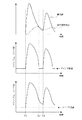
図3は、実施の形態1に係る残響抑制装置において得られるゲインを説明する図である。まず、図3における時刻T1以前では、入力信号(ここでは、第kの周波数帯域の成分)の振幅が継続的にゼロであり、瞬時値X(k)および推定残響成分R(k)はゼロとなるため、ゲイン導出部6から出力されるゲインG1(k)はゲイン下限値となる。
FIG. 3 is a diagram for explaining the gain obtained in the dereverberation apparatus according to the first embodiment. First, before time T1 in FIG. 3, the amplitude of the input signal (here, the component in the kth frequency band) is continuously zero, and the instantaneous value X (k) and the estimated reverberation component R (k) are zero. Therefore, the gain G1 (k) output from the
その後、時刻T1において、入力信号の振幅が現れると、瞬時値X(k)は、立ち上がり、推定残響成分R(k)は、瞬時値X(k)に遅れながら立ち上がっていく。そして、入力信号の振幅が低くなっていくと、瞬時値X(k)はすぐに小さくなっていくが、推定残響成分R(k)は遅れて小さくなっていくので、瞬時値X(k)と推定残響成分R(k)が交差する場合がある。瞬時値X(k)と推定残響成分R(k)が同一の値になる時刻を時刻T2とする。つまり、時刻T1から時刻T2までの期間では、推定残響成分R(k)は、瞬時値X(k)より小さくなっており、時刻T2を過ぎると、推定残響成分R(k)は、瞬時値X(k)より大きくなる。本発明の実施の形態に係る残響抑制装置では、X(k)<R(k)となる時間帯の音を後期残響音と見做し、その時間帯のゲインG1(k)を下限値に下げることで、簡易に効果的な後期残響音の抑制を実現することを特徴としている。 Thereafter, when the amplitude of the input signal appears at time T1, the instantaneous value X (k) rises, and the estimated reverberation component R (k) rises with a delay from the instantaneous value X (k). Then, as the amplitude of the input signal decreases, the instantaneous value X (k) immediately decreases, but the estimated reverberation component R (k) decreases with a delay, so the instantaneous value X (k) And the estimated reverberation component R (k) may intersect. The time when the instantaneous value X (k) and the estimated reverberation component R (k) become the same value is defined as time T2. That is, in the period from time T1 to time T2, the estimated reverberation component R (k) is smaller than the instantaneous value X (k), and after the time T2, the estimated reverberation component R (k) is an instantaneous value. It becomes larger than X (k). In the reverberation suppressing apparatus according to the embodiment of the present invention, a sound in a time zone where X (k) <R (k) is regarded as a late reverberation sound, and the gain G1 (k) in that time zone is set to a lower limit value. By lowering, it is easy to effectively suppress late reverberation.
そのため、時刻T1から時刻T2においては、ゲイン導出部6から出力されるゲインG1(k)は、(下限値以上であれば)計算式(1)のG(k)となり、時刻T2を過ぎ、次に瞬時値X(k)が推定残響成分R(k)を上回る時刻T3までの時間については、ゲイン導出部6から出力されるゲインG1(k)を、ゲイン下限値に固定する。
Therefore, from time T1 to time T2, the gain G1 (k) output from the
実施の形態1に係る残響抑制装置を音響製品に応用する場合、時刻T1,T2,T3におけるゲインG1(k)の変化が急峻となるため、処理後の音声が非常に聞き取りにくい音になってしまう場合があることがわかった。これを解消するために、ゲインG1(k)にスムージング処理を施すようにした。
When the dereverberation apparatus according to
図3に示すように、スムージング処理部7によりゲインG1(k)の急峻な変化が抑えられ、このように急峻な変化が抑えられたゲインG2(k)がゲイン処理部2によって使用される。
As shown in FIG. 3, the smoothing
このようにして、各時点におけるゲインG2(k)が得られる。 In this way, the gain G2 (k) at each time point is obtained.
そして、ゲイン処理部2は、所定数の周波数帯域の成分に対して、スムージング処理部7により得られたゲインG2(k)をそれぞれ適用し、合成フィルタバンク3は、ゲイン処理部2によりゲインを適用された所定数の周波数帯域の成分を合成して出力信号を生成する。
Then, the
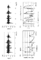
図4は、実施の形態1に係る残響抑制装置による後期残響音抑制の具体例について説明する図である。図4(A)は、入力信号の一例を示しており、図4(B)は、図4(A)に示す入力信号における1つの周波数帯域の成分についての瞬時値および推定残響成分の一例を示しており、図4(C)は、図4(B)に示す瞬時値および推定残響成分に基づくゲインG1(k),G2(k)の一例を示しており、図4(D)は、図4(C)に示すゲインを含む、所定数の周波数帯域の成分についてのゲインを適用して得られる出力信号の一例を示している。 FIG. 4 is a diagram illustrating a specific example of late reverberation suppression by the reverberation suppression apparatus according to the first embodiment. 4A shows an example of an input signal, and FIG. 4B shows an example of an instantaneous value and an estimated reverberation component for one frequency band component in the input signal shown in FIG. 4A. FIG. 4C shows an example of gains G1 (k) and G2 (k) based on the instantaneous values and the estimated reverberation components shown in FIG. 4B, and FIG. FIG. 5 shows an example of an output signal obtained by applying gains for a predetermined number of frequency band components including the gain shown in FIG.
図4(B)および図4(C)に示すように、推定残響成分R(k)が瞬時値X(k)より大きくなる期間(つまり、直接音や初期反射音の成分より残響成分が優勢であると推定される期間)においては、入力信号の振幅が継続的にゼロである期間と同様にゲインG1(k)が下限値に抑えられ、推定残響成分R(k)が瞬時値X(k)より小さくなる期間(つまり、残響成分より直接音や初期反射音の成分が優勢であると推定される期間)においては、ゲインG1(k)が、計算式(1)のG(k)に示すように変動する。そして、このようにゲインを調整することで、図4(D)に示すように、出力信号において、後期残響成分が優勢な期間の振幅が抑えられる。 As shown in FIGS. 4B and 4C, the period during which the estimated reverberation component R (k) is larger than the instantaneous value X (k) (that is, the reverberation component is dominant over the direct sound and the component of the initial reflected sound). In the period during which the amplitude of the input signal is continuously zero, the gain G1 (k) is suppressed to the lower limit value, and the estimated reverberation component R (k) is the instantaneous value X ( k) In a period smaller than that (that is, a period in which the component of the direct sound and the early reflection sound is predominated over the reverberation component), the gain G1 (k) is G (k) in the calculation formula (1). It fluctuates as shown in Then, by adjusting the gain in this way, as shown in FIG. 4D, the amplitude of the period in which the late reverberation component is dominant is suppressed in the output signal.
以上のように、上記実施の形態1によれば、瞬時値算出部4は、入力信号の絶対値または2乗に相関がある値のエンベロープにおける瞬時値を算出し、残響推定部5は、その瞬時値の指数移動平均を推定残響成分として算出し、ゲイン導出部6は、瞬時値が推定残響成分より大きい期間においては、推定残響成分および瞬時値に基づいて入力信号に対するゲインを導出し、瞬時値が推定残響成分より小さい期間においてはゲインを下限値にする。そして、スムージング処理部7は、ゲイン導出部6により導出されたゲインに対してスムージング処理を行い、ゲイン処理部2は、スムージング処理後のゲインを入力信号の振幅調整に適用する。
As described above, according to the first embodiment, the instantaneous
これにより、比較的簡単な演算で残響が抑制される。 Thereby, reverberation is suppressed by a comparatively simple calculation.
実施の形態2.
実施の形態2では、本発明に係る残響抑制装置が補聴器に応用される。図5は、本発明の実施の形態2に係る補聴器の構成を示すブロック図である。
In
図5に示す補聴器は、マイクロホン21、イヤホン22、および補聴処理部23を備える。マイクロホン21は、音響を検出し、検出した音響に応じた音響信号を出力する。イヤホン22は、音響信号を入力され、入力された音響信号に応じた音響を出力する。
The hearing aid shown in FIG. 5 includes a
補聴処理部23は、音声処理部31、ゲイン処理部32、および出力制限部33を有する。音声処理部31は、上述の周波数帯域ごとに、ノイズリダクション、スペクトル強調などの信号処理を行う。ゲイン処理部32は、上述のゲイン処理部2と同様に、上述の周波数帯域ごとにゲインを適用する。出力制限部33は、所定の最大音圧を超えないように出力音圧を制限する。
The hearing
なお、実施の形態2におけるその他の構成要素については実施の形態1のものと同様であるので、その説明を省略する。 Since the other components in the second embodiment are the same as those in the first embodiment, the description thereof is omitted.
実施の形態2では、マイクロホン21から出力された音響信号が、図示せぬA/D(Analog to Digital)変換部を介して分析フィルタバンク1に入力され、実施の形態1と同様にしてゲインが導出され、ゲイン処理部32に入力される。そして、出力制限部33(つまり、補聴処理部23)から出力される各周波数帯域の成分が合成フィルタバンク3に入力され、合成フィルタバンク3からの出力信号が、図示せぬD/A(Digital to Analog)変換部、アンプなどを介してイヤホン22に出力される。
In the second embodiment, the acoustic signal output from the
なお、上述の各実施の形態は、本発明の好適な例であるが、本発明は、これらに限定されるものではなく、本発明の要旨を逸脱しない範囲において、種々の変形、変更が可能である。 Each embodiment described above is a preferred example of the present invention, but the present invention is not limited to these, and various modifications and changes can be made without departing from the scope of the present invention. It is.
例えば、上記実施の形態1,2において、入力信号は、デジタル信号でもアナログ信号でもよい。 For example, in the first and second embodiments, the input signal may be a digital signal or an analog signal.
また、上記実施の形態1において、周波数分布が狭い音響信号については、フィルタバンクを使用せずに、単一の周波数帯域の音響信号として処理してもよい。 In the first embodiment, an acoustic signal having a narrow frequency distribution may be processed as an acoustic signal in a single frequency band without using a filter bank.
さらに、上記実施の形態1,2において、上述の所定数の周波数帯域のうちの低周波数側の一部の周波数帯域(例えば、1kHz以下の周波数帯域、32の周波数帯域のうちの低周波数側の7つの周波数帯域など)に対してのみ、上述の後期残響抑制を適用するようにしてもよい。 Furthermore, in the first and second embodiments, a part of the low frequency side of the predetermined number of frequency bands (for example, a frequency band of 1 kHz or less, a low frequency side of the 32 frequency bands, The above-mentioned late reverberation suppression may be applied only to seven frequency bands.
さらに、上記実施の形態1に係る残響抑制装置は、例えば、トンネル内などの残響の大きい空間での音声の採取、録音などに使用できる。 Furthermore, the reverberation suppressing apparatus according to the first embodiment can be used, for example, for collecting and recording sound in a space with large reverberation such as in a tunnel.
本発明は、例えば、補聴器などに適用可能である。 The present invention is applicable to, for example, a hearing aid.
1 分析フィルタバンク
2,32 ゲイン処理部
3 合成フィルタバンク
4 瞬時値算出部
5 残響推定部
6 ゲイン導出部
7 スムージング処理部
DESCRIPTION OF
Claims (5)
前記瞬時値算出部により算出される前記瞬時値の指数移動平均を推定残響成分として算出する残響推定部と、
前記瞬時値が前記推定残響成分より大きい期間においては、前記推定残響成分および前記瞬時値に基づいて前記入力信号に対するゲインを導出し、前記瞬時値が前記推定残響成分より小さい期間においては、前記ゲインを下限値にするゲイン導出部と、
前記ゲイン導出部により導出された前記ゲインに対してスムージング処理を行うスムージング処理部と、
前記スムージング処理後の前記ゲインを前記入力信号の振幅調整に適用するゲイン処理部と、
を備えることを特徴とする残響抑制装置。 An instantaneous value calculation unit for calculating an instantaneous value in an envelope of a value correlated with the absolute value or square of the input signal;
A reverberation estimation unit that calculates an exponential moving average of the instantaneous value calculated by the instantaneous value calculation unit as an estimated reverberation component;
In a period when the instantaneous value is larger than the estimated reverberation component, a gain for the input signal is derived based on the estimated reverberation component and the instantaneous value, and in a period where the instantaneous value is smaller than the estimated reverberation component, the gain is derived. A gain derivation unit that sets the lower limit to
A smoothing processing unit that performs a smoothing process on the gain derived by the gain deriving unit;
A gain processing unit that applies the gain after the smoothing processing to amplitude adjustment of the input signal;
A reverberation suppressing device comprising:
合成フィルタバンクとをさらに備え、
前記ゲイン処理部は、前記所定数の周波数帯域の成分に対してゲインをそれぞれ適用し、
前記合成フィルタバンクは、前記ゲイン処理部により前記ゲインを適用された前記所定数の周波数帯域の成分を合成し、
前記瞬時値算出部は、前記所定数の周波数帯域の成分のそれぞれについて、前記成分の絶対値または2乗に相関がある値のエンベロープにおける瞬時値を算出し、
前記残響推定部は、前記所定数の周波数帯域の成分のそれぞれについて、前記瞬時値算出部により算出される前記瞬時値の指数移動平均を推定残響成分として算出し、
前記ゲイン導出部は、前記所定数の周波数帯域の成分のそれぞれについて、前記瞬時値が前記推定残響成分より大きい期間においては、前記推定残響成分および前記瞬時値に基づいて前記入力信号に対するゲインを導出し、前記瞬時値が前記推定残響成分より小さい期間においては、前記ゲインを下限値に固定し、
前記スムージング処理部は、前記所定数の周波数帯域の成分のそれぞれについて、前記ゲイン導出部により導出された前記ゲインに対してスムージング処理を行い、
前記ゲイン処理部は、前記所定数の周波数帯域の成分に対して、前記スムージング処理後のゲインをそれぞれ適用すること、
を特徴とする請求項1から請求項4のうちのいずれか1項記載の残響抑制装置。 An analysis filter bank that divides the input signal into components of a predetermined number of frequency bands;
A synthesis filter bank,
The gain processing unit applies a gain to each component of the predetermined number of frequency bands,
The synthesis filter bank synthesizes the components of the predetermined number of frequency bands to which the gain is applied by the gain processing unit,
The instantaneous value calculation unit calculates an instantaneous value in an envelope of a value correlated with an absolute value or a square of the component for each of the components of the predetermined number of frequency bands,
The reverberation estimation unit calculates an exponential moving average of the instantaneous value calculated by the instantaneous value calculation unit as an estimated reverberation component for each of the components of the predetermined number of frequency bands,
The gain deriving unit derives a gain for the input signal based on the estimated reverberation component and the instantaneous value in a period in which the instantaneous value is larger than the estimated reverberation component for each of the components of the predetermined number of frequency bands. In a period in which the instantaneous value is smaller than the estimated reverberation component, the gain is fixed to a lower limit value,
The smoothing processing unit performs a smoothing process on the gain derived by the gain deriving unit for each of the components of the predetermined number of frequency bands,
The gain processing unit applies the gain after the smoothing process to the predetermined number of frequency band components,
The dereverberation apparatus according to any one of claims 1 to 4, wherein:
Priority Applications (2)
| Application Number | Priority Date | Filing Date | Title |
|---|---|---|---|
| JP2014179656A JP6371167B2 (en) | 2014-09-03 | 2014-09-03 | Reverberation suppression device |
| US14/836,332 US9530429B2 (en) | 2014-09-03 | 2015-08-26 | Reverberation suppression apparatus used for auditory device |
Applications Claiming Priority (1)
| Application Number | Priority Date | Filing Date | Title |
|---|---|---|---|
| JP2014179656A JP6371167B2 (en) | 2014-09-03 | 2014-09-03 | Reverberation suppression device |
Publications (2)
| Publication Number | Publication Date |
|---|---|
| JP2016054421A JP2016054421A (en) | 2016-04-14 |
| JP6371167B2 true JP6371167B2 (en) | 2018-08-08 |
Family
ID=55403208
Family Applications (1)
| Application Number | Title | Priority Date | Filing Date |
|---|---|---|---|
| JP2014179656A Active JP6371167B2 (en) | 2014-09-03 | 2014-09-03 | Reverberation suppression device |
Country Status (2)
| Country | Link |
|---|---|
| US (1) | US9530429B2 (en) |
| JP (1) | JP6371167B2 (en) |
Families Citing this family (6)
| Publication number | Priority date | Publication date | Assignee | Title |
|---|---|---|---|---|
| JP7264594B2 (en) | 2018-02-23 | 2023-04-25 | リオン株式会社 | Reverberation suppression device and hearing aid |
| EP3573058B1 (en) * | 2018-05-23 | 2021-02-24 | Harman Becker Automotive Systems GmbH | Dry sound and ambient sound separation |
| DE102018210143A1 (en) * | 2018-06-21 | 2019-12-24 | Sivantos Pte. Ltd. | Method for suppressing acoustic reverberation in an audio signal |
| JP7083724B2 (en) * | 2018-08-10 | 2022-06-13 | リオン株式会社 | Reverberation suppressor and hearing aid |
| JP7208365B2 (en) * | 2018-09-18 | 2023-01-18 | ホアウェイ・テクノロジーズ・カンパニー・リミテッド | Apparatus and method for adapting virtual 3D audio into a real room |
| CN109801643B (en) * | 2019-01-30 | 2020-12-04 | 龙马智芯(珠海横琴)科技有限公司 | Processing method and device for reverberation suppression |
Family Cites Families (10)
| Publication number | Priority date | Publication date | Assignee | Title |
|---|---|---|---|---|
| KR101149591B1 (en) * | 2004-07-22 | 2012-05-29 | 코닌클리케 필립스 일렉트로닉스 엔.브이. | Audio signal dereverberation |
| US8284947B2 (en) | 2004-12-01 | 2012-10-09 | Qnx Software Systems Limited | Reverberation estimation and suppression system |
| JP2007065204A (en) * | 2005-08-30 | 2007-03-15 | Nippon Telegr & Teleph Corp <Ntt> | Reverberation removing apparatus, reverberation removing method, reverberation removing program, and recording medium thereof |
| WO2007058121A1 (en) * | 2005-11-15 | 2007-05-24 | Nec Corporation | Reverberation suppressing method, device, and reverberation suppressing program |
| US7856353B2 (en) * | 2007-08-07 | 2010-12-21 | Nuance Communications, Inc. | Method for processing speech signal data with reverberation filtering |
| US9100767B2 (en) * | 2008-11-21 | 2015-08-04 | Auro Technologies | Converter and method for converting an audio signal |
| JP5751110B2 (en) * | 2011-09-22 | 2015-07-22 | 富士通株式会社 | Reverberation suppression apparatus, reverberation suppression method, and reverberation suppression program |
| JP6019969B2 (en) * | 2011-11-22 | 2016-11-02 | ヤマハ株式会社 | Sound processor |
| JP5834948B2 (en) * | 2012-01-24 | 2015-12-24 | 富士通株式会社 | Reverberation suppression apparatus, reverberation suppression method, and computer program for reverberation suppression |
| CN102750956B (en) * | 2012-06-18 | 2014-07-16 | 歌尔声学股份有限公司 | Method and device for removing reverberation of single channel voice |
-
2014
- 2014-09-03 JP JP2014179656A patent/JP6371167B2/en active Active
-
2015
- 2015-08-26 US US14/836,332 patent/US9530429B2/en active Active
Also Published As
| Publication number | Publication date |
|---|---|
| JP2016054421A (en) | 2016-04-14 |
| US20160064011A1 (en) | 2016-03-03 |
| US9530429B2 (en) | 2016-12-27 |
Similar Documents
| Publication | Publication Date | Title |
|---|---|---|
| JP6371167B2 (en) | Reverberation suppression device | |
| US10354634B2 (en) | Method and system for denoise and dereverberation in multimedia systems | |
| JP5817366B2 (en) | Audio signal processing apparatus, method and program | |
| US9357307B2 (en) | Multi-channel wind noise suppression system and method | |
| JP5672770B2 (en) | Microphone array device and program executed by the microphone array device | |
| JP2017516126A (en) | Noise suppression | |
| EP2755204A1 (en) | Noise suppression device and method | |
| US9538288B2 (en) | Sound field correction apparatus, control method thereof, and computer-readable storage medium | |
| JP5081245B2 (en) | Directional microphone device | |
| JP5785674B2 (en) | Voice dereverberation method and apparatus based on dual microphones | |
| US20190267018A1 (en) | Signal processing for speech dereverberation | |
| WO2014097637A1 (en) | Directional microphone device, audio signal processing method and program | |
| CN112272848A (en) | Background noise estimation using gap confidence | |
| JPWO2010087147A1 (en) | Howling suppression device, howling suppression method, program, and integrated circuit | |
| JP6083872B2 (en) | System and method for reducing unwanted sound in a signal received from a microphone device | |
| JP6631010B2 (en) | Microphone selection device, microphone system, and microphone selection method | |
| JP2006243644A (en) | Method for reducing noise, device, program, and recording medium | |
| JP2012175453A (en) | Speech processing device, speech processing method and program | |
| JP7083724B2 (en) | Reverberation suppressor and hearing aid | |
| CN109326297B (en) | Adaptive post-filtering | |
| WO2020110228A1 (en) | Information processing device, program and information processing method | |
| WO2013111348A1 (en) | Method and device for controlling directionality | |
| JP7264594B2 (en) | Reverberation suppression device and hearing aid | |
| KR102063824B1 (en) | Apparatus and Method for Cancelling Acoustic Feedback in Hearing Aids | |
| JP4518817B2 (en) | Sound collection method, sound collection device, and sound collection program |
Legal Events
| Date | Code | Title | Description |
|---|---|---|---|
| A621 | Written request for application examination |
Free format text: JAPANESE INTERMEDIATE CODE: A621 Effective date: 20170823 |
|
| A977 | Report on retrieval |
Free format text: JAPANESE INTERMEDIATE CODE: A971007 Effective date: 20180615 |
|
| TRDD | Decision of grant or rejection written | ||
| A01 | Written decision to grant a patent or to grant a registration (utility model) |
Free format text: JAPANESE INTERMEDIATE CODE: A01 Effective date: 20180705 |
|
| A61 | First payment of annual fees (during grant procedure) |
Free format text: JAPANESE INTERMEDIATE CODE: A61 Effective date: 20180712 |
|
| R150 | Certificate of patent or registration of utility model |
Ref document number: 6371167 Country of ref document: JP Free format text: JAPANESE INTERMEDIATE CODE: R150 |
|
| R250 | Receipt of annual fees |
Free format text: JAPANESE INTERMEDIATE CODE: R250 |
|
| R250 | Receipt of annual fees |
Free format text: JAPANESE INTERMEDIATE CODE: R250 |