JP6369960B2 - Inverter and method, particularly as part of a power grid - Google Patents
Inverter and method, particularly as part of a power grid Download PDFInfo
- Publication number
- JP6369960B2 JP6369960B2 JP2016547175A JP2016547175A JP6369960B2 JP 6369960 B2 JP6369960 B2 JP 6369960B2 JP 2016547175 A JP2016547175 A JP 2016547175A JP 2016547175 A JP2016547175 A JP 2016547175A JP 6369960 B2 JP6369960 B2 JP 6369960B2
- Authority
- JP
- Japan
- Prior art keywords
- power
- inverter
- mpp
- tracking
- characteristic curve
- Prior art date
- Legal status (The legal status is an assumption and is not a legal conclusion. Google has not performed a legal analysis and makes no representation as to the accuracy of the status listed.)
- Active
Links
Images


Classifications
-
- G—PHYSICS
- G05—CONTROLLING; REGULATING
- G05F—SYSTEMS FOR REGULATING ELECTRIC OR MAGNETIC VARIABLES
- G05F1/00—Automatic systems in which deviations of an electric quantity from one or more predetermined values are detected at the output of the system and fed back to a device within the system to restore the detected quantity to its predetermined value or values, i.e. retroactive systems
- G05F1/66—Regulating electric power
- G05F1/67—Regulating electric power to the maximum power available from a generator, e.g. from solar cell
-
- H—ELECTRICITY
- H02—GENERATION; CONVERSION OR DISTRIBUTION OF ELECTRIC POWER
- H02J—CIRCUIT ARRANGEMENTS OR SYSTEMS FOR SUPPLYING OR DISTRIBUTING ELECTRIC POWER; SYSTEMS FOR STORING ELECTRIC ENERGY
- H02J3/00—Circuit arrangements for ac mains or ac distribution networks
- H02J3/38—Arrangements for parallely feeding a single network by two or more generators, converters or transformers
- H02J3/381—Dispersed generators
-
- H—ELECTRICITY
- H02—GENERATION; CONVERSION OR DISTRIBUTION OF ELECTRIC POWER
- H02M—APPARATUS FOR CONVERSION BETWEEN AC AND AC, BETWEEN AC AND DC, OR BETWEEN DC AND DC, AND FOR USE WITH MAINS OR SIMILAR POWER SUPPLY SYSTEMS; CONVERSION OF DC OR AC INPUT POWER INTO SURGE OUTPUT POWER; CONTROL OR REGULATION THEREOF
- H02M7/00—Conversion of ac power input into dc power output; Conversion of dc power input into ac power output
- H02M7/42—Conversion of dc power input into ac power output without possibility of reversal
- H02M7/44—Conversion of dc power input into ac power output without possibility of reversal by static converters
-
- H—ELECTRICITY
- H02—GENERATION; CONVERSION OR DISTRIBUTION OF ELECTRIC POWER
- H02J—CIRCUIT ARRANGEMENTS OR SYSTEMS FOR SUPPLYING OR DISTRIBUTING ELECTRIC POWER; SYSTEMS FOR STORING ELECTRIC ENERGY
- H02J2300/00—Systems for supplying or distributing electric power characterised by decentralized, dispersed, or local generation
- H02J2300/20—The dispersed energy generation being of renewable origin
- H02J2300/22—The renewable source being solar energy
- H02J2300/24—The renewable source being solar energy of photovoltaic origin
- H02J2300/26—The renewable source being solar energy of photovoltaic origin involving maximum power point tracking control for photovoltaic sources
-
- Y—GENERAL TAGGING OF NEW TECHNOLOGICAL DEVELOPMENTS; GENERAL TAGGING OF CROSS-SECTIONAL TECHNOLOGIES SPANNING OVER SEVERAL SECTIONS OF THE IPC; TECHNICAL SUBJECTS COVERED BY FORMER USPC CROSS-REFERENCE ART COLLECTIONS [XRACs] AND DIGESTS
- Y02—TECHNOLOGIES OR APPLICATIONS FOR MITIGATION OR ADAPTATION AGAINST CLIMATE CHANGE
- Y02E—REDUCTION OF GREENHOUSE GAS [GHG] EMISSIONS, RELATED TO ENERGY GENERATION, TRANSMISSION OR DISTRIBUTION
- Y02E10/00—Energy generation through renewable energy sources
- Y02E10/50—Photovoltaic [PV] energy
- Y02E10/56—Power conversion systems, e.g. maximum power point trackers
Description
本発明は、発電機のDC電力をグリッド対応のAC電力に変換するためのインバータ、複数のインバータを備える発電網、および発電機のDC電力をグリッド対応のAC電力に変換するための方法に関する。 The present invention relates to an inverter for converting DC power of a generator into AC power corresponding to a grid, a power generation network including a plurality of inverters, and a method for converting DC power of a generator into AC power corresponding to a grid.
再生可能エネルギー用の発電設備は、公共電気グリッド向けに生成されるエネルギーの量に大きく寄与するので、これらの設備によってエネルギーが供給される範囲を必要に応じて制限して、たとえば、接続された負荷による消費電力が低い場合に電気グリッドを安定化し、または急に用立てることが可能な予備電力を利用可能な状態に保っておくことが望ましい。供給を制限するための、すなわちディレーティングするための実現可能な1つの方法は、最適な動作点MPP(最大電力点)において利用可能な電力のうち既定の割合だけを、接続された電気グリッドにこの設備が供給するよう、この設備を制御することにあり、また実現可能な別の方法は、決められた絶対値、たとえば定格電力のうち既定の割合だけディレーティングすることにある。この事前定義を最適に満たすためには、設備の発電機の出力可能な最大電力を知ることが必要である。時間が経過する間に、たとえば光電発電機の場合には、照射が変化することによってこの電力が大きく変化することがあるので、定期的に現在のMPP電力値を更新することが必要である。このためには、十分な範囲にわたって発電機の特性曲線を追跡することが必要であり、この特性曲線は発電機のMPPを含み、または外挿することによってMPPの位置を推定可能にする。この範囲での発電機の特性を解析するためには、設備から装置に供給される電力が、出力低下電力からある程度著しくずれるようにすることが必要になる場合がある。 Power generation facilities for renewable energy greatly contribute to the amount of energy generated for the public electricity grid, so the range of energy supplied by these facilities is limited as necessary and connected, for example It is desirable to keep the power grid available so that it can stabilize the electrical grid when the power consumption by the load is low, or can be turned up quickly. One feasible way to limit the supply, ie derating, is to use only a predetermined percentage of the power available at the optimal operating point MPP (maximum power point) to the connected electrical grid. The facility is to control the facility to supply, and another possible method is to derate a predetermined absolute value, eg, a predetermined percentage of the rated power. In order to optimally satisfy this predefined definition, it is necessary to know the maximum power that can be output by the generator of the facility. As time elapses, for example in the case of a photoelectric generator, this power may change significantly due to changes in illumination, so it is necessary to periodically update the current MPP power value. This requires tracking the generator's characteristic curve over a sufficient range, which includes or extrapolates the generator's MPP so that the position of the MPP can be estimated. In order to analyze the characteristics of the generator in this range, it may be necessary for the power supplied from the facility to the apparatus to deviate significantly from the output reduced power to some extent.
独国特許出願公開第102010038941A1号明細書の文書には、各インバータのうち1つのインバータがMPPで動作し、発電網の全電力が既定の値に対応するよう、その他のインバータがその電力を適応させるような方式で、共通の制御装置を介して動作する複数のインバータのネットワークが開示してある。この解決策は、関係するインバータと共通の制御装置との間の通信オーバヘッドが重くならざるを得ない。さらには、特に、非常に低い出力低下電力までディレーティングする場合、発電網の設備を永続的にMPPで動作させることが常に可能とは限らない。 The document DE 102010038941A1 states that one inverter of each inverter operates at MPP and that the other inverters adapt its power so that the total power of the grid corresponds to a predetermined value. In such a manner, a network of a plurality of inverters operating via a common control device is disclosed. This solution has to increase the communication overhead between the inverters involved and the common controller. Furthermore, especially when derating to very low power reduction power, it is not always possible to permanently operate the power grid equipment with MPP.
したがって、発電網内において、MPPを決定している間に、既定の出力低下電力からの電力のずれを補償することができるインバータであって、この発電網内においては、関係するインバータ間の通信が最低限に抑えられ、また頑強になるインバータを提供することが本発明の一目的である。通信を最小限に抑え、また頑強にして、インバータの補償型電力供給を可能にする方法を提供することが、さらに本発明の一目的である。 Accordingly, an inverter capable of compensating for a deviation in power from a predetermined output reduction power while determining the MPP in the power generation network, in which communication between related inverters is performed. It is an object of the present invention to provide an inverter that can be minimized and is robust. It is a further object of the present invention to provide a method that minimizes communication and is robust and allows for compensated power supply of the inverter.
この目的は、請求項1に記載のインバータ、請求項7に記載の発電網、および請求項13に記載の方法によって実現される。有利な実施形態が、従属クレームに記載されている。
This object is achieved by an inverter according to claim 1, a power grid according to claim 7, and a method according to
発電機の直流電力をグリッド対応の交流電力に変換するための本発明によるインバータは、MPP電力値PMPPを決定するために、発電機の特性曲線の少なくとも1つの部分を追跡するための走査ユニットを備える。出力低下電力Predまでディレーティングする場合、インバータにイネーブル信号が存在する場合にのみ、インバータは、出力低下電力Predからずれた第1の電力プロファイルを有する特性曲線の追跡を起動する。インバータは、開始信号および終了信号をそれぞれ出力することによって特性曲線の追跡を指示する。さらに、インバータは、たとえば発電網の別のインバータから開始信号を受信すると、交流電力としての第2の電力プロファイルを提供するように構成され、第1の電力プロファイルは、出力低下電力Predからの第2の電力プロファイルのずれの符号とは逆の符号で、出力低下電力Predからずれている。具体的には、第1の電力プロファイルは正の符号でずれている。すなわち、第1の電力プロファイルでは、出力低下電力と比較して電力値が増加する。第2の電力プロファイルの逆の符号によって実現されるのは、本発明による第2のインバータが上記の開始信号を生成し、その第1の電力プロファイルが出力低下電力からずれている発電網において、このずれが、第2の電力プロファイルによって少なくとも部分的に補償されることである。しかし、発電網の本発明による別のインバータは、その第2の電力プロファイルで前記ずれを相殺するのに寄与することができる。その他のインバータの第2の電力プロファイルによって補償するために、インバータのうちの1つのインバータによって特性曲線を追跡している間、発電網によって生成される総合電力の、総合出力低下電力からのずれは、その特性曲線を追跡するインバータの第1の電力プロファイルの、その出力低下電力からのずれよりも小さい。 An inverter according to the invention for converting generator DC power into grid-compatible AC power comprises a scanning unit for tracking at least one part of a generator characteristic curve in order to determine an MPP power value P MPP. Is provided. When derating to output reduced power Pred , the inverter activates tracking characteristic curves having a first power profile that deviates from output reduced power Pred only if an enable signal is present in the inverter. The inverter instructs the tracking of the characteristic curve by outputting a start signal and an end signal, respectively. In addition, the inverter is configured to provide a second power profile as AC power, for example upon receipt of a start signal from another inverter of the power grid, wherein the first power profile is derived from the reduced output power Pred . The sign of the second power profile is opposite to the sign of the deviation, and is deviated from the output reduced power Pred . Specifically, the first power profile is shifted by a positive sign. That is, in the first power profile, the power value increases as compared with the output reduced power. Realized by the opposite sign of the second power profile, in a power grid in which the second inverter according to the invention generates the start signal and the first power profile deviates from the reduced power output, This deviation is at least partially compensated by the second power profile. However, another inverter according to the invention of the power grid can contribute to canceling out the deviation with its second power profile. While tracking the characteristic curve by one of the inverters to compensate by the second power profile of the other inverter, the deviation of the total power generated by the power grid from the total output drop power is The first power profile of the inverter that tracks the characteristic curve is smaller than the deviation from the reduced output power.
電力プロファイルという用語は、供給される電力の時間プロファイルを意味するものと理解され、これは、この追跡を制御するのに使用されるパラメータの事前定義とは独立に、発電機の特性曲線のターゲットとなる追跡の結果として生じる。この追跡は、たとえば、発電機の電圧、発電機の電流、または発電機の電力の、時間依存する事前定義によって実行してもよい。 The term power profile is understood to mean the time profile of the delivered power, which is independent of the predefined parameters used to control this tracking, As a result of tracking. This tracking may be performed, for example, by a time-dependent pre-definition of generator voltage, generator current, or generator power.
一実施形態では、インバータの発電機特性曲線を追跡するインバータは、続いて、通信インターフェースを介して現時点のMPP電力値PMPPを提供する。前記値が発電網の他のインバータに伝送され、そこでこれを使用して、この他のインバータの現時点でのMPP電力値の推定値を変更してもよく、出力低下電力が前記推定値に基づく。このようにして、特性曲線の追跡をそれぞれのインバータによって新たに実行する必要なく、発電機による発電の外部条件の変化、たとえば照射の変化を考慮に入れることが可能である。これにより、たとえば、既定の割合のMPP電力値として、またはある一定割合の出力低下電力だけ低減されたMPP電力値として、出力低下電力が選択されることになり、出力低下電力の適応がMPP電力値の変化に時間的に近接して実行されるものである場合、必要となる走査プロセスの数を著しく低減することができる。 In one embodiment, the inverter that tracks the generator characteristic curve of the inverter then provides the current MPP power value P MPP via the communication interface. The value may be transmitted to other inverters in the power grid, where it may be used to change the current MPP power value estimate for the other inverter, and the power drop is based on the estimated value . In this way, it is possible to take into account changes in the external conditions of power generation by the generator, for example changes in irradiation, without having to perform a new tracking of the characteristic curve by each inverter. Thereby, for example, the output reduced power is selected as the MPP power value at a predetermined ratio or as the MPP power value reduced by a certain ratio of the output reduced power, and the adaptation of the output reduced power is determined as the MPP power. The number of scanning processes required can be significantly reduced if performed close in time to the change in value.
特に、発電網の個々のインバータが互いに遠く離れて配置される場合、イネーブル信号、開始信号、および/または終了信号は、インターネット接続を介して伝送してもよい。あるいは、これらの信号を伝送するための共通のラインもしくは別々のライン、または無線伝送を使用してもよい。 In particular, if the individual inverters of the power grid are located far away from each other, the enable signal, the start signal and / or the end signal may be transmitted via an internet connection. Alternatively, a common line or separate lines for transmitting these signals, or wireless transmission may be used.
本発明による発電網は、本発明による2つ以上のインバータを備え、これらのインバータは、イネーブル信号、開始信号、および終了信号を交換するために互いに接続されている。場合によっては制御装置が設けられ、これが発電網の各インバータに接続され、イネーブル信号を生成する。この場合、イネーブル信号は、個々のインバータもしくはネットワークのインバータの部分群に選択的に送信してもよく、またはそれらにのみ有効でもよい。しかし、独立した制御装置の代わりに、インバータのうちの1つがこの機能を実行してもよく、またはこの機能をインバータの部分群もしくはその全てに分散してもよい。 The power grid according to the present invention comprises two or more inverters according to the present invention, which are connected to each other for exchanging enable signals, start signals and end signals. In some cases, a control device is provided, which is connected to each inverter of the power grid to generate an enable signal. In this case, the enable signal may be selectively transmitted to individual inverters or a subset of inverters of the network, or may be valid only for them. However, instead of a separate controller, one of the inverters may perform this function, or this function may be distributed to a subset or all of the inverters.
イネーブル信号の生成に関わっている制御装置またはインバータは、発電網内での走査プロセスの順序および頻度を決定する。この場合、トークンを用いて、特性曲線の追跡を交互に起動することを制御してもよい。現在走査プロセスを実行しているインバータによって、終了後に別のインバータにトークンが渡され、それにより、このインバータとしては、走査プロセスを実行できるようになり、受信インバータはまた、走査プロセスを使用することなくトークンを渡してもよい。 The controller or inverter involved in generating the enable signal determines the order and frequency of the scanning process within the power grid. In this case, a token may be used to control alternately starting tracking of the characteristic curve. The inverter that is currently performing the scanning process passes the token to another inverter after the completion, so that this inverter can perform the scanning process, and the receiving inverter must also use the scanning process. You may pass a token instead.
本発明の別の一実施形態では、インバータのうち少なくとも1つのインバータが、適応設定が調整可能な発電機に接続され、発電機の電圧を変更する代わりに発電機の適応設定を変更することによって、走査プロセス中に第1の電力プロファイルを提供する。 In another embodiment of the present invention, at least one of the inverters is connected to a generator whose adaptive setting is adjustable, by changing the adaptive setting of the generator instead of changing the voltage of the generator. Providing a first power profile during the scanning process.
発電機の特性曲線の少なくとも1つの部分を追跡するための走査ユニットを備えるインバータによって、発電機の直流電力をグリッド対応の交流電力に変換するための本発明による方法は、出力低下電力にまで低減された状態にインバータがある場合にはMPP電力値を決定するのに役立つ。この方法は、インバータにおいてイネーブル信号が存在するという事前条件の下で、出力低下電力からずれている第1の電力プロファイルを有する特性曲線を追跡するステップを含む。開始信号は特性曲線の追跡の始まりに送信され、終了信号は特性曲線の追跡の終わりに送信される。開始信号、たとえば発電網の別のインバータによって生成される開始信号を受信する場合、インバータは、交流電力としての第2の電力プロファイルを提供し、第1の電力プロファイルは、出力低下電力からの第2の電力プロファイルのずれの符号とは逆の符号で、出力低下電力からずれている。 By means of an inverter with a scanning unit for tracking at least one part of the generator characteristic curve, the method according to the invention for converting generator DC power into grid-compatible AC power reduces to reduced output power If there is an inverter in the programmed state, it will help determine the MPP power value. The method includes tracking a characteristic curve having a first power profile that deviates from reduced power under a precondition that an enable signal is present at the inverter. The start signal is sent at the beginning of the characteristic curve tracking and the end signal is sent at the end of the characteristic curve tracking. When receiving a start signal, e.g., a start signal generated by another inverter of the power grid, the inverter provides a second power profile as AC power, the first power profile being the second power profile from the output reduced power. 2 is a sign opposite to the sign of the power profile deviation, and deviates from the reduced power output.
本発明による方法の一修正形態では、この方法は、第1のインバータおよび第2のインバータ上で共同して実行される。この場合、第1の特性曲線の追跡は、第1のインバータでの設定値の段階的な増加によって実行され、第2の特性曲線の追跡は、第2のインバータでの設定値の段階的な減少(増加分の補償)によって並列に実行される。第1のインバータが、もはや設定値の事前定義に従わなくてもよくなるまで、設定値の増加が継続してもよい。実現される最も高い設定値が、第1のインバータでのMPP電力値を決定してもよい。 In a modification of the method according to the invention, the method is performed jointly on the first inverter and the second inverter. In this case, the tracking of the first characteristic curve is performed by stepwise increase of the set value in the first inverter, and the tracking of the second characteristic curve is stepped of the set value in the second inverter. Performed in parallel with a decrease (compensation for the increase). The increase in set value may continue until the first inverter no longer has to follow the preset pre-set value. The highest setting value that is realized may determine the MPP power value at the first inverter.
続いて、第2のインバータのMPP電力値を決定するために、第1の特性曲線の追跡は、第2のインバータでの設定値の段階的な増加によって実行してもよく、第2の特性曲線の追跡は、第1のインバータでの設定値の段階的な減少によって実行してもよく、前記減少が、第2のインバータの設定値の増加分を補償する。この場合は、実現される最も高い設定値が、第2のインバータでのMPP電力値を決定する。 Subsequently, in order to determine the MPP power value of the second inverter, the tracking of the first characteristic curve may be performed by a step-wise increase of the set value in the second inverter. The tracking of the curve may be performed by a gradual decrease in the set value in the first inverter, the decrease compensating for the increase in the set value in the second inverter. In this case, the highest setting value that is realized determines the MPP power value at the second inverter.
制御ユニット、または2つのインバータのうちの一方によって、様々な設定値を生成し、送信してもよい。イネーブル信号、ならびに開始信号および終了信号は、独立した信号として構成してもよく、または様々な設定値によって暗黙のうちに送信してもよい。一例として、送信される第1の設定値は開始信号またはイネーブル信号と解釈してもよく、出力低下電力に起因する設定値は終了信号と解釈してもよい。 Various setting values may be generated and transmitted by the control unit or one of the two inverters. The enable signal and the start and end signals may be configured as independent signals or may be transmitted implicitly with various settings. As an example, the first set value to be transmitted may be interpreted as a start signal or an enable signal, and the set value resulting from the power reduction power may be interpreted as an end signal.
インバータは、複数の個々のインバータを含むインバータ・グループによって形成してもよく、個々のインバータに割り当てられた個々の特性曲線を追跡するこのグループの個々のインバータによって特性曲線を追跡するステップが、時間的にオーバラップするよう連続して実行される。この実施形態では、第2の電力プロファイルは、それを提供するため、個々のインバータの間で任意に分配してもよい。 The inverter may be formed by an inverter group including a plurality of individual inverters, and the step of tracking the characteristic curves by the individual inverters of this group that tracks the individual characteristic curves assigned to the individual inverters is time Are continuously executed so as to overlap each other. In this embodiment, the second power profile may be arbitrarily distributed among the individual inverters to provide it.
各図を用いて、本発明を以下に説明する。 The present invention will be described below with reference to the drawings.
図1には、接続された発電機11、具体的には光電発電機の直流電力を、接続されたグリッド12、たとえば単相グリッドまたは多相グリッド、具体的には三相グリッドに伝送される交流電力に変換するための、本発明によるインバータ10が示してある。インバータ・ブリッジ13が電力変換用に使用され、このインバータ・ブリッジ13によって変換される電力が走査ユニット14を用いて設定できるような形で、前記インバータ・ブリッジは走査ユニット14を介して制御可能である。
In FIG. 1, the DC power of a connected generator 11, specifically a photoelectric generator, is transmitted to a
走査ユニット14は、バス17を介して送信される信号を受信するように構成される。走査ユニット14は、第1のラインを介してイネーブル信号15を受信してもよく、第2のラインを介して開始信号16を送受信してもよい。さらに、走査ユニット14は、第2のラインを介して終了信号を送信あるいは受信してもよく、終了信号を別々のラインを介して送信することも同様に考えられる。第1のラインおよび第2のラインはまた、別々のラインまたは共通ラインでもよく、具体的には通信接続でもよい。一例として、バス17がインターネットを含むこと、および各信号がインターネット接続を用いて伝送されることが考えられる。別のインバータあるいは制御ユニット(図示せず)をバス17に接続して、各インバータ間および/またはインバータと制御ユニットの間で、イネーブル信号、開始信号、および/または終了信号を伝送してもよい。
The
走査ユニット14は、発電機11の特性曲線の追跡を起動し、それを制御して、そのMPP電力値PMPPを決定するのに役立つ。すなわち、発電機11が所与の時点で、どれくらいの最大電力を生成できるのか決定するのに役立つ。出力可能な最大電力に応じてディレーティングが規定される場合に、この状態での出力低下電力を決定するためには、特にインバータ10の出力低下状態においてこれが重要である。本発明によるインバータ10の場合、走査ユニット14は、イネーブル信号15が走査ユニットに存在する場合にのみ、こうした特性曲線の追跡を起動するように構成される。特性曲線の追跡の始まりは開始信号16によって示され、特性曲線の追跡の終わりは終了信号によって識別される。特性曲線の追跡期間中、すなわち開始信号16と終了信号の間では、制御装置により、イネーブル信号15は、バス17を介して伝送されないか、またはインバータ10に存在しないことが確実になる。あるいは、インバータ10は、この期間をイネーブル信号15が存在しない期間として解釈するよう構成してもよく、通常は、バス17に接続された別のインバータによって開始信号および終了信号が送信される場合のみが関連している。これにより、それぞれの場合において、バス17を介して互いに接続されているインバータ・ネットワークの各インバータのうちの1つのインバータのみが、所与の時点で特性曲線の追跡を確実に実行する。
The
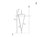
図2には、左側の第1の図として、発電機11の特性曲線20が示してあり、電力がY軸にプロットしてあり、発電機の電圧がX軸にプロットしてある。図2の右側では、第2の図に、インバータ10の特性曲線20の追跡中に生じる電力プロファイル24’、25’の2つの例が示してあり、時間がX軸にプロットしてあり、電力がY軸にプロットしてある。特性曲線20の対応する追跡経路24、25が、第1の図に示してある。
FIG. 2 shows a
電力プロファイル24’に対応して特性曲線20を追跡する第1の変形形態では、インバータ10は初めに、動作点21において出力低下状態にあり、出力低下電力Predをグリッド12に出力する。開始時点tSで始まり、インバータ10が出力する電力が線形の増加速度で増加し、その結果、発電機11の動作点が、電圧を上昇させるようにシフトする。MPP23でMPP電力プロファイルPMPPに達すると、発電機は、必要とする電力をもはや生成できなくなることがある。この時点tEにおいて、発電機は、動作点22で再び出力低下状態になり、グリッドに供給される電力が出力低下電力Predまで低減し、終了信号が送信される。取得したMPP電力値PMPPが所定のMPP電力値からずれている場合、特性曲線20の追跡が終了した後に、それに応じて出力低下電力Predを適応してもよい。
In a first variant in which the
電力プロファイル25’に従って特性曲線20を追跡する第2の変形形態では、インバータ10は初めに、動作点22において出力低下電力Predで出力低下状態にある。ここで、開始時点tSにおいて、グリッド12に出力された電力プロファイル25’が、MPP23に達するまで傾斜する形で増加する。この時点tMにおいて、中心信号を送信してもよく、動作点21で再び出力低下電力Predに達するまで、電力が傾斜しながら低減する。この場合も同様に、割り当てられた追跡経路25においてMPP23に達するので、ここでも同様に、MPP23でのMPP電力値PMPPは、追跡の終わりに知られており、出力低下電力Predで考慮に入れてもよい。
In a second variant, in which the
図示した2つの電力プロファイル24’、25’の代わりとして、他の電力プロファイルを考えることもでき、この電力プロファイルは、動作点21と22の間の発電機11の動作点での遷移、または、動作点21、22のうちの一方から先に進んで、特性曲線20の一部分を追跡する動作点での遷移につながり、この特性曲線20は、MPP23での現在存在するMPP電力値PMPPについての結論を引き出すことが可能になるのに十分であって、終了時点tEにおいて、特性曲線20の追跡が始まった動作点で再び終了する。電力プロファイルはまた、既定の電圧または電流のプロファイルが追跡され、発電機11の現在の特性曲線に基づいて、対応する電力プロファイルが確立されるという事実から得ることができる。
As an alternative to the two
図3には、本発明による方法の例示的な流れ図が示してあり、この方法では、バス17に接続された別のインバータから開始信号16を受信したかどうか、初めにインバータ10が検査する。このような開始信号を受信すると、インバータ10は、時間的に一定の出力低下電力Predの代わりに、時間的に可変の第2の電力プロファイルを提供し始める。バス17を介して終了信号が受信されるまで、第2の電力プロファイルが提供される。次いで、インバータ10は、時間的に一定な出力低下電力を供給するステップに戻る。あるいは、第2の電力プロファイルは、開始信号16で始まって、終了信号の受信とは関係なく提供してもよく、または、終了信号は、第2の電力プロファイルが完全に経過すると生成してもよく、バス17を介して伝送してもよい。最後に述べた変形形態では、バス17を介して終了信号を受信すると、次いで、第1の電力プロファイルの追跡を終了してもよい。これは、先に完全に追跡された電力プロファイルが、終了信号の提供につながり、したがって、それぞれ他の電力プロファイルの追跡の終了につながる実施形態を包含する。
FIG. 3 shows an exemplary flowchart of the method according to the invention, in which the
開始信号を受信していない場合、インバータ10は、バス17を介してイネーブル信号15が存在しているかどうか、および特性曲線の追跡が必要かどうか検査する。両方の場合において、インバータ10は、開始信号16を送信し、第1の電力プロファイルを有する特性曲線20を追跡し始める。特性曲線20の追跡が終了して後、インバータ10は、終了信号を送信し、出力低下状態まで戻り、ここで出力低下電力は、特性曲線の追跡によって改めて決定されたMPP電力値PMPPに関連することが好ましい。場合によっては、インバータ10は、この更新されたMPP電力値PMPPを、別々の通信インターフェースを介して、またはバス17を介して接続された他のインバータに利用可能とする。これらのインバータは、出力低下電力Predのその値を、この更新されたMPP電力値PMPPを用いて適合させて、たとえば照射の変化を考慮に入れてもよい。
If no start signal is received, the
図4の本発明による発電網140では、本発明による方法を使用する複数のインバータの相互作用が、一例に基づいて示してある。図4の左側では、第1のインバータ100、第2のインバータ110、および第3のインバータ120が、それぞれの場合にバス17を介して互いに接続されている。バスを介して、イネーブル信号105、115、125、および開始信号106、116、126、および割り当てられた終了信号を、走査ユニット104、114、124を用いて各インバータ間で送受信してもよい。さらに、制御装置130はバス17に接続されており、この制御装置を使用して、たとえば開始信号106、116、126、および各終了信号を用いて、対応するイネーブル信号105、115、125を生成してもよく、ここでイネーブル信号は、具体的にはそれぞれのインバータについて、ならびに非特異的にはインバータの全てについて有効でもよい。したがって、制御装置130は、個々のインバータ、一群のインバータ、または各インバータの全てについてイネーブル信号を生成してもよい。このようにして、制御装置130は、発電網140の各インバータがそれぞれの特性曲線を追跡する際の順序および周波数を、付随して決定または規定してもよい。あるいは、しかし、各インバータが互いにこの順序を決定することも考えられる。たとえば、各インバータ間でトークンを渡すことによって、これを実行してもよい。しかし、イネーブル信号が存在する場合、各インバータ自体が、その特性曲線を追跡する時点を決定するという事実に基づいて、この順序がインバータ間の調整なしに得られることもある。したがって、制御装置130はまた、発電網140内に存在しなくてもよい。
In the
インバータ100、110、120のそれぞれが、接続された発電機100、111、121の直流電力を、インバータにそれぞれ割り当てられたインバータ・ブリッジ103、113、123を用いて交流電力に変換し、接続されたグリッド12にこの交流電力を供給する。変換される電力は、受信信号に応じて、インバータのそれぞれの走査ユニット104、114、124を用いて制御してもよい。
Each of the
本発明による方法を実行する結果として得られる例示的な電力プロファイルが、3つの図の形で図4の右側部分に示してあり、これらの図は、それぞれが3つのインバータ100、110、120のうちの1つに割り当てられており、時間がX軸にプロットされ、電力がY軸にプロットされている。この場合、右上の図がインバータ100に割り当てられ、右中央の図がインバータ110に割り当てられ、右下の図がインバータ120に割り当てられている。段階Iでは、全てのインバータが出力低下状態にあり、それぞれの場合に出力低下電力Predを供給する。使用可能になる時点tFにおいて、イネーブル信号は、少なくとも第1のインバータ100に存在する。段階IIが始まる開始時点tSにおいて、第1のインバータ100が開始信号106を送信し、第1の電力プロファイル108を有するその発電機の特性曲線を追跡し始める。図示した場合には、第1の電力プロファイル108は、第1のインバータ100の線形に増加するコンバータ電力を含む。第2の段階IIは終了時点tEで終了し、この時点でインバータ100が終了信号を送信し、出力低下状態に戻り、ここでインバータ100は、後続の段階IIIにおいて、特性曲線を追跡している間に決定される現在のMPP電力値PMPPを考慮に入れる、変更済みの出力低下電力を供給する。
An exemplary power profile resulting from carrying out the method according to the invention is shown in the right-hand part of FIG. 4 in the form of three diagrams, which show three
右中央の図には、第2のインバータ110の電力プロファイル118が示してある。開始時点tSにおいて、第2のインバータ110は、第1のインバータ100の開始信号を受信し、その出力で第2の電力プロファイル118を提供する。図示した例では、コンバータの電力が時間とともに線形に減少する。終了時点tEにおいて、第2のインバータ110は、第1のインバータ100の終了信号を受信し、出力低下状態に戻り、ここで、第1のインバータ100によって提供された現在のMPP電力値に応じて、出力低下電力Predが適合される。図示した例では、第2のインバータ110の第2の電力プロファイル118は、第1のインバータ100の第1の電力プロファイル108のそれぞれの出力低下電力Predからのずれを補償し、その結果、両方のインバータの電力出力の合計は、開始時点tSの前での出力低下電力Predの合計に実質上または正確に対応する。これにより、現在のMPP電力値PMPPを決定するための特性曲線の追跡が、発電網140の累積の電力出力の、ディレーティングの事前定義からのずれにつながらないようになる。
In the right center diagram, the
図2を参照すると、この図は、増大電力傾斜と減少電力傾斜の間で変化すると中心信号が送信される電力プロファイルを有する特性曲線の追跡を説明しており、したがって一代替実施形態(図示せず)では、補償しているインバータ110の第2の電力プロファイルは、初めに電力傾斜が減少し、次いで電力傾斜が増大し、中心信号を受信するとこれらの電力傾斜間の変化が生じる。
Referring to FIG. 2, this figure illustrates the tracking of a characteristic curve having a power profile in which a center signal is transmitted as it changes between increasing and decreasing power slopes, and thus an alternative embodiment (not shown). 1), the second power profile of the
右下の図には、第3のインバータ120の電力プロファイルが示してある。開始時点tSにおいて、第3のインバータ120は、その出力低下状態を抜けることはなく、したがって、その電力プロファイル128は、その出力低下電力Predの時間的に一定の値を維持する。したがって、この例では、第3のインバータ120は、特性曲線の追跡中、発電網140のインバータのうち1つのインバータの電力のずれを補償することに関与しない。終了時点tEにおいて、第3のインバータ120はまた、第1のインバータ100から伝達された現在のMPP電力値に応じて、その出力低下電力Predを適合させる。
In the lower right diagram, the power profile of the
別の一実施形態では、発電網140のインバータのうち1つのインバータの、その特性曲線を追跡している間の電力のずれは、発電網140のその他のインバータのうちの複数、具体的には全てのインバータによって共同して補償してもよい。電力のずれの補償への寄与は、関係のあるインバータの間で等しく分散してもよく、または適切に重み付けして分散してもよい。1つの有利な構成においては、インバータ間で固定の割当てを実施してもよく、この割当てによって、どのインバータ、またはインバータのどの部分群が、ネットワークの別のインバータの電力のずれを補償するのかが規定される。これは、送信するインバータの識別表示を、送信される開始信号に付加することによって簡略な方式で実施してもよく、その結果、補償するためには、送信するインバータに第2の電力プロファイルが割り当てられる場合にのみ、受信するインバータがその第2の電力プロファイルを提供する。
In another embodiment, the power divergence while tracking the characteristic curve of one of the inverters of the
電力のずれを可能な限り完全に補償できるようにするため、特性曲線を追跡している間に、第1の電力プロファイルを事前決定するとともに実現可能にすること、および、これを決定しないかまたは特性曲線の推移によってほんのわずかだけ決定することが有利である。理想的には、第1の電力プロファイルの推移は特性曲線の推移には依存せず、むしろ特性曲線の推移が単に、特性曲線の追跡の開始時点tSと終了時点tEの間の持続時間を決定する。このようにして、特性曲線を追跡するインバータの電力のずれの程度を発電網の各インバータ間に伝達して、前記電力のずれを十分に、またはさらに完全に補償することは必要でない。既定の第1の電力プロファイルの代わりに、電圧または電流のプロファイルがインバータ100によって事前定義され、これから、発電機の特性曲線に応じて第1の電力プロファイルが生じる場合、一般に、電力のずれのほんの部分的な補償だけが実現可能なので、より容易に実現できる特性曲線の追跡に有利なように、ここでは完全な補償なしで済ます。
In order to be able to compensate for the power deviation as completely as possible, pre-determining and enabling the first power profile while tracking the characteristic curve and / or not determining this It is advantageous to determine only slightly by the course of the characteristic curve. Ideally, the transition of the first power profile does not depend on the transition of the characteristic curve; rather, the transition of the characteristic curve is simply the duration between the start time t S and the end time t E of the tracking of the characteristic curve. To decide. In this way, it is not necessary to communicate the degree of power deviation of the inverter that tracks the characteristic curve between the inverters of the power grid to fully or even fully compensate for the power deviation. If a voltage or current profile is predefined by the
別の一実施形態では、発電網140の複数の個々のインバータを含むインバータ・グループ内での発電機の特性曲線の追跡は、個々のインバータが特性曲線の追跡を連続して実行するように、ただし時間的にオーバラップするよう協調して実行される。この場合、個々の追跡プロセスを調整するため、一定の時間オフセットを選択してもよく、または、信号たとえば前述の中心信号が交換される。一例としては、個々のインバータとして図4のインバータ100および110が、このようなグループ150を形成する。図5には、この実施形態が実施されるときの発電網140の例示的な電力プロファイルが示してあり、上図には、個々のインバータとしてのインバータ100、110のグループ150の、第1の電力プロファイル108’、118’が示してある。次いで、下図には、インバータ120の第2の電力プロファイル128’が示してあり、これが、第1の電力プロファイル108’、118’の合計として、グループ150の組み合わされた電力プロファイル158を補償する。開始時点tSにおいて、インバータ100は、増大電力傾斜によって、そのMPPの方向にその特性曲線を追跡し始め、開始信号106が生成される。t1の時点でMPPに達すると、インバータ100が、減少電力傾斜によって出力されるその電力を低減した後、再び出力低下電力Predに達し、インバータ100は出力低下状態に変化する。同時に、t1の時点において、インバータ110は、その電力を傾斜するよう増加させ始めた後に、t2の時点でそのMPPに達し、電力が傾斜して減少するよう変化する。tEの時点において、インバータ110は、再び出力低下状態に達し、終了信号が生成される。したがって、グループ150は、組み合わされた第1の電力プロファイル158を開始信号から終了信号までの間で出力することによって、本発明による個々のインバータと同等に動作する。グループ150の出力低下電力Predからの組み合わされた電力プロファイル158のずれは、開始信号の時点と終了信号の時点との間で第2の電力プロファイル128’を出力することにより、インバータ120によって補償され、インバータ120は、必要な場合、プロファイルの推移を適合させることによって、t1、t2の時点において中心信号に反応してもよい。
In another embodiment, tracking the generator characteristic curve within an inverter group that includes a plurality of individual inverters of the
開始信号および終了信号は原則として、グループ150の任意の個々のインバータによって生成してもよく、この開始信号および終了信号は、同じインバータによって生成されるか、または互いに異なるインバータによって生成される。それ自体の特性曲線を追跡する個々のインバータは、まず開始信号を送信し、終了信号は、その特性曲線を最後に追跡する個々のインバータによって送信されることが好ましい。中間の時点t1、t2は、中心信号を交換することによって調整してもよく、または関係のある個々のインバータは、開始信号に対する既定の持続時間によってこれらの時点を決定する。さらに、個々のインバータの特性曲線の追跡の始まりは、MPPに達する時点とは関係なく、別の個々のインバータが選択してもよい。
The start signal and end signal may in principle be generated by any individual inverter of the
本発明による方法の別の有利な実施形態では、特性曲線を追跡すること、または電力プロファイルを提供することは、制御ユニット130、または発電網の各インバータのうち1つのインバータが、電力出力の複数の設定値を第1のインバータに連続して送信することによって実現される。影響を受けた第1のインバータは、設定値に対応する電力を供給しようとし、その結果を送信ユニットに報告して戻す。この結果は、たとえば、得られた電力値の形で、または設定値の完全な取得を通知する論理信号の形で送信してもよい。設定値を取得すると、設定値を取得しなくてもよいとインバータが通知するまで、送信された後続の設定値が段階的に増加してもよい。次いで、取得された最後の設定値は、MPP電力値PMPPと解釈してもよい。出力低下電力を超える設定値を第1のインバータに伝送するとともに発電網の総合電力を補償するために、第2の設定値が第2のインバータに伝送され(または、複数の設定値が複数のインバータに伝送され)、この設定値が出力低下電力と比較して低減され、その結果、発電網の総合電力は一定またはほとんど一定のままである。
In another advantageous embodiment of the method according to the invention, tracking the characteristic curve or providing the power profile means that the
MPP電力値PMPPを取得した後、新規の設定値を事前定義することによって、インバータは出力低下電力まで段階的に戻ってもよく、単一ステップによって出力低下電力まで戻ることは除外されない。第2のインバータまたは対応するインバータ・グループに対する電力事前定義の補償が並列に実行されて、出力低下電力まで戻る間にも総合電力を確実に一定に保つ。その後、別のインバータの特性曲線の追跡を同様に開始してもよい。このようにして構成された方法によって、前述の方法のいくつかと比較して通信オーバヘッドが増大することになるが、出力低下電力からの発電網のずれを完全に補償できるようにすることが確実に可能となる。 After obtaining the MPP power value P MPP , by predefining a new set value, the inverter may return step by step to the output reduced power, and it is not excluded to return to the output reduced power by a single step. Power pre-defined compensation for the second inverter or corresponding inverter group is performed in parallel to ensure that the total power remains constant while returning to reduced power. Thereafter, tracking of the characteristic curve of another inverter may be started in the same manner. The method configured in this way will increase the communication overhead compared to some of the methods described above, but will ensure that the deviation of the power grid from the reduced power output can be fully compensated. It becomes possible.
前述の方法の一修正形態では、総合電力を監視することによって、設定値を取得することについての結果を報告して戻すことは不要としてもよい。設定値が、第1のインバータの実現可能な最大電力を超える場合、これが、超過分の範囲に対応する総合電力の降下につながる。この方法では、総合電力の降下が閾値を超えるまで、設定値の修正値が増大する。次いで、MPP電力値PMPPは、総合電力の降下がない最後の設定値に対応する。 In a modification of the above method, it may not be necessary to report back the result of obtaining the set value by monitoring the total power. If the set value exceeds the maximum achievable power of the first inverter, this leads to a drop in the total power corresponding to the excess range. In this method, the correction value of the set value increases until the total power drop exceeds the threshold value. The MPP power value P MPP then corresponds to the last set value with no overall power drop.
図6には、第1および第2のインバータの時間的な電力推移200、210が示してあり、また前述の方法の結果としての総合電力の電力推移220が示してある。設定値の変化によって、t1の時点において前記第1のインバータがもはや設定値に追従しなくてもよくなるまで、第1のインバータの電力200が段階的に増加する。同時に、補償ステップにおいて第2のインバータの電力210が段階的に減少し、その結果、総合電力220は一定のままである。その結果、t1の時点の後、総合電力220は、規定の限界値230を下回って降下するまで減少することになる。次いで、両方のインバータの電力が、元の出力低下電力まで戻る。変更されたMPP電力値PMPPが決定された場合、両方のインバータの電力は、あるいは、それに応じて変更された出力低下電力まで戻ってもよい。
FIG. 6 shows temporal power transitions 200 and 210 of the first and second inverters, and a
グループ150の全てのインバータまたは複数のインバータによって特性曲線を同時に追跡する場合と比較して、このグループ150内で特性曲線を時間オフセットで追跡することにより、このグループの組み合わされた電力プロファイルの、グループの共通の出力低下電力からの最大の電力のずれが既に減少することに留意されたい。
By tracking the characteristic curve with time offset within this
10 インバータ
11 発電機
12 グリッド
13 インバータ・ブリッジ
14 走査ユニット
15 イネーブル信号
16 開始信号
17 バス
20 特性曲線
21、22 動作点
23 MPP
24、25 追跡経路
24’、25’ 電力プロファイル
100、110、120 インバータ
101、111、121 発電機
103、113、123 インバータ・ブリッジ
104、114、124 走査ユニット
105、115、125 イネーブル信号
106、116、126 開始信号
108、118、128 電力プロファイル
108’、118’、128’ 電力プロファイル
130 制御ユニット
140 発電網
150 グループ
158 電力プロファイル
200、210、220 電力推移
230 限界値
DESCRIPTION OF
24, 25 Tracking path 24 ', 25'
Claims (16)
前記インバータ(10)は、出力低下電力(Pred)にディレーティングされる場合、開始信号(116)を受信しておらず、且つ、イネーブル信号(15)が前記インバータ(10)に存在している場合にのみ、前記出力低下電力(Pred)からずれている第1の電力プロファイル(24’、25’、108)を有する前記特性曲線(20)の追跡を起動し、開始信号(16)および終了信号をそれぞれ出力することによって、前記追跡の開始および終了を示すように構成され、
前記インバータ(10)が、開始信号(116)を受信すると交流電力としての第2の電力プロファイル(118)を提供するように構成され、
MPPを決定している間に、既定の出力低下電力(Pred)からの電力のずれを補償するため、前記第1の電力プロファイル(24’、25’、108)が、前記出力低下電力(Pred)からの前記第2の電力プロファイル(118)のずれの符号とは逆の符号で、前記出力低下電力(Pred)からずれていることを特徴とするインバータ(10)。 In the inverter (10) for converting the DC power of the generator (11) to AC power corresponding to the grid , at least a part of the characteristic curve (20) of the generator (11) is tracked, and the MPP power value (P A scanning unit (14) for determining MPP ),
When the inverter (10) is derated to output reduced power (P red ), it does not receive the start signal (116) and the enable signal (15) is present in the inverter (10). Only when the tracking of the characteristic curve (20) with the first power profile (24 ′, 25 ′, 108) deviating from the output reduced power (P red ) is activated, and the start signal (16) Configured to indicate the start and end of the tracking by outputting and
The inverter (10) is configured to provide a second power profile (118) as alternating current power upon receipt of a start signal (116);
While compensating for the MPP, the first power profile (24 ′, 25 ′, 108) is configured to reduce the output reduced power (P red ) to compensate for a power deviation from a predetermined output reduced power (P red ). the inverter and the second shift of the code power profile (118) from P red) with opposite sign, characterized in that deviates from the output decrease power (P red) (10).
前記インバータ(10)において開始信号(116)を受信しておらず、且つ、イネーブル信号(15)が存在するという事前条件の下で、前記出力低下電力(Pred)からずれている第1の電力プロファイル(24’、25’、108)を有する前記特性曲線(20)を追跡するステップと、
− 前記特性曲線(20)の前記追跡の始まりに開始信号(16)を送信し、前記特性曲線(20)の前記追跡の終わりに終了信号を送信するステップと、
開始信号(116)を受信すると交流電力としての第2の電力プロファイル(118)を提供するステップであって、MPPを決定している間に、既定の出力低下電力(Pred)からの電力のずれを補償するため、前記第1の電力プロファイル(24’、25’、108)が、前記出力低下電力(Pred)からの前記第2の電力プロファイル(118)のずれの符号とは逆の符号で、前記出力低下電力(Pred)からずれているステップとを含むことを特徴とする方法。 By tracking at least a part of the characteristic curve (20) of the generator (11), the MPP power value (P MPP ) is obtained when the inverter (10) is in a state reduced to the reduced output power (P red ). In a method for converting DC power of the generator (11) into grid-compatible AC power by means of an inverter (10) comprising a scanning unit (14) for determining,
The first signal deviating from the output reduced power (P red ) under a precondition that the start signal (116) is not received in the inverter (10) and the enable signal (15) is present. Tracking said characteristic curve (20) having a power profile (24 ', 25', 108);
-Transmitting a start signal (16) at the beginning of the tracking of the characteristic curve (20) and transmitting an end signal at the end of the tracking of the characteristic curve (20);
Receiving a start signal (116) to provide a second power profile (118) as alternating current power, while determining the MPP, the power from a predetermined reduced output power (P red ) To compensate for the deviation, the first power profile (24 ′, 25 ′, 108) is opposite to the sign of the deviation of the second power profile (118) from the reduced power output (P red ). And a step deviating from said reduced power output (P red ).
Applications Claiming Priority (3)
| Application Number | Priority Date | Filing Date | Title |
|---|---|---|---|
| DE102014100690.9 | 2014-01-22 | ||
| DE102014100690.9A DE102014100690A1 (en) | 2014-01-22 | 2014-01-22 | INVERTER, PARTICULARLY AS PART OF AN ENERGY PRODUCTION ASSOCIATION, AND METHOD |
| PCT/EP2015/050932 WO2015110400A1 (en) | 2014-01-22 | 2015-01-20 | Inverter, in particular as part of a power generation network, and method |
Publications (3)
| Publication Number | Publication Date |
|---|---|
| JP2017504122A JP2017504122A (en) | 2017-02-02 |
| JP2017504122A5 JP2017504122A5 (en) | 2018-03-01 |
| JP6369960B2 true JP6369960B2 (en) | 2018-08-08 |
Family
ID=52396675
Family Applications (1)
| Application Number | Title | Priority Date | Filing Date |
|---|---|---|---|
| JP2016547175A Active JP6369960B2 (en) | 2014-01-22 | 2015-01-20 | Inverter and method, particularly as part of a power grid |
Country Status (7)
| Country | Link |
|---|---|
| US (1) | US10355491B2 (en) |
| EP (1) | EP3097624B1 (en) |
| JP (1) | JP6369960B2 (en) |
| CN (1) | CN106463969B (en) |
| DE (1) | DE102014100690A1 (en) |
| ES (1) | ES2672921T3 (en) |
| WO (1) | WO2015110400A1 (en) |
Families Citing this family (3)
| Publication number | Priority date | Publication date | Assignee | Title |
|---|---|---|---|---|
| US9811064B2 (en) * | 2015-04-27 | 2017-11-07 | Solarcity Corporation | Energy generation (EG) system generating failsafe level of energy in case of communication failure |
| CN108879756B (en) | 2018-06-15 | 2022-03-25 | 华为技术有限公司 | Control method, controller, inverter and inversion system of string type inverter |
| CN110719038B (en) * | 2019-09-09 | 2021-02-12 | 华为数字技术(苏州)有限公司 | Control method, device and system of string inverter and storage medium |
Family Cites Families (13)
| Publication number | Priority date | Publication date | Assignee | Title |
|---|---|---|---|---|
| DE3212022A1 (en) * | 1982-03-31 | 1983-10-06 | Siemens Ag | METHOD AND DEVICE FOR THE AUTOMATIC SETTING OF THE OPTIMAL WORKING POINT OF A DC VOLTAGE SOURCE |
| DE102009032288A1 (en) * | 2009-07-09 | 2011-01-13 | Kostal Industrie Elektrik Gmbh | photovoltaic system |
| DE102009040091A1 (en) * | 2009-09-04 | 2011-03-10 | Voltwerk Electronics Gmbh | Island unit of an island power network for communicating energy requests with another island unit |
| US8334489B2 (en) * | 2010-03-10 | 2012-12-18 | Sunpower Corporation | Photovoltaic system with managed output and method of managing variability of output from a photovoltaic system |
| DE102010038941A1 (en) | 2010-08-05 | 2012-02-09 | Sma Solar Technology Ag | Detection of a possible, but not actually fed, feed-in energy quantity of a photovoltaic system |
| DE202010016207U1 (en) * | 2010-12-03 | 2012-03-06 | Voltwerk Electronics Gmbh | photovoltaic system |
| JP5786655B2 (en) * | 2011-11-02 | 2015-09-30 | ソニー株式会社 | Control system, control device, and control method |
| CN104160577B (en) * | 2012-01-17 | 2017-11-07 | 英飞凌科技奥地利有限公司 | Power converter circuit, power-supply system and method |
| CN103365333B (en) * | 2012-03-31 | 2014-12-03 | 阳光电源股份有限公司 | MPPT (maximum power point tracking) scanning method for photovoltaic arrays |
| US9160175B2 (en) * | 2012-05-08 | 2015-10-13 | Vpp Energy Zrt. | Distributed power generation system, control means and method for controlling the power generation of the system |
| EP3499695A1 (en) * | 2012-05-25 | 2019-06-19 | Solaredge Technologies Ltd. | Circuit for interconnected direct current power sources |
| DE102012217455A1 (en) | 2012-09-26 | 2013-09-12 | Siemens Aktiengesellschaft | Method for controlling a photovoltaic system with fluctuating irradiation |
| KR101471612B1 (en) * | 2013-07-01 | 2014-12-12 | 남부대학교산학협력단 | Solar position Tracking Precision Measurement system based on precision optical lenses. |
-
2014
- 2014-01-22 DE DE102014100690.9A patent/DE102014100690A1/en not_active Withdrawn
-
2015
- 2015-01-20 ES ES15701158.6T patent/ES2672921T3/en active Active
- 2015-01-20 CN CN201580005539.9A patent/CN106463969B/en active Active
- 2015-01-20 EP EP15701158.6A patent/EP3097624B1/en active Active
- 2015-01-20 WO PCT/EP2015/050932 patent/WO2015110400A1/en active Application Filing
- 2015-01-20 JP JP2016547175A patent/JP6369960B2/en active Active
-
2016
- 2016-07-19 US US15/213,439 patent/US10355491B2/en active Active
Also Published As
| Publication number | Publication date |
|---|---|
| DE102014100690A1 (en) | 2015-07-23 |
| US10355491B2 (en) | 2019-07-16 |
| WO2015110400A1 (en) | 2015-07-30 |
| ES2672921T3 (en) | 2018-06-18 |
| EP3097624A1 (en) | 2016-11-30 |
| JP2017504122A (en) | 2017-02-02 |
| CN106463969B (en) | 2019-09-17 |
| US20170012436A1 (en) | 2017-01-12 |
| CN106463969A (en) | 2017-02-22 |
| EP3097624B1 (en) | 2018-03-14 |
Similar Documents
| Publication | Publication Date | Title |
|---|---|---|
| JP6369960B2 (en) | Inverter and method, particularly as part of a power grid | |
| US8659181B2 (en) | Power line communication method for transmitting data signal with splitting of power transmission interval | |
| US8681517B2 (en) | AC converter, AC converting method, and storage medium for converting an AC voltage with a relatively high frequency into an AC voltage with a relatively low frequency | |
| AU2015321143A1 (en) | Method for generating an alternating electric current | |
| WO2014103055A1 (en) | Power conversion device and power conversion method | |
| CN116094190A (en) | Method and device for operating a device for wireless energy transmission in the direction of a consumer by means of inductive coupling | |
| US8330431B2 (en) | Method for smoothing alternating electric current from a number of power generating units and wind power plant including a number of wind mills with variable rotational speed | |
| JP5410551B2 (en) | Power converter | |
| CN108521848B (en) | Network feedback unit and electric drive system | |
| JP2017504122A5 (en) | ||
| CN102403729B (en) | Converter control system | |
| JP6146149B2 (en) | Grid-connected inverter device, communication device, and current generation method | |
| CN104025440A (en) | Controller for a transducer, transducer, and control method | |
| US20160359425A1 (en) | Frequency Converter | |
| CN112514223A (en) | Selecting a switching time of a wind turbine converter | |
| JP6799502B2 (en) | Power conversion device for photovoltaic power generation and control method of power converter for photovoltaic power generation | |
| JP6511345B2 (en) | Power conversion apparatus and method for heat treatment | |
| JP6964788B2 (en) | Power conversion system | |
| WO2017188135A1 (en) | Operating circuit and method for operating at least one illuminant | |
| JP2011050123A (en) | Control unit for phase advanced capacitor | |
| RU2339993C1 (en) | Method of reversible pulse dc voltage converter control with stabilisation of limit current | |
| JP2006238615A (en) | Power converter | |
| JP2016214039A (en) | Control system for rotary electric machine | |
| Magazinnik | OPTIMIZATION OF THE CONTROL OVER A TRANSISTOR INVERTER SCHEME | |
| KR20160051067A (en) | Power factor collection method for wind power generator using current control |
Legal Events
| Date | Code | Title | Description |
|---|---|---|---|
| A521 | Request for written amendment filed |
Free format text: JAPANESE INTERMEDIATE CODE: A523 Effective date: 20180119 |
|
| A621 | Written request for application examination |
Free format text: JAPANESE INTERMEDIATE CODE: A621 Effective date: 20180119 |
|
| A871 | Explanation of circumstances concerning accelerated examination |
Free format text: JAPANESE INTERMEDIATE CODE: A871 Effective date: 20180119 |
|
| A975 | Report on accelerated examination |
Free format text: JAPANESE INTERMEDIATE CODE: A971005 Effective date: 20180326 |
|
| A131 | Notification of reasons for refusal |
Free format text: JAPANESE INTERMEDIATE CODE: A131 Effective date: 20180403 |
|
| A521 | Request for written amendment filed |
Free format text: JAPANESE INTERMEDIATE CODE: A523 Effective date: 20180530 |
|
| TRDD | Decision of grant or rejection written | ||
| A01 | Written decision to grant a patent or to grant a registration (utility model) |
Free format text: JAPANESE INTERMEDIATE CODE: A01 Effective date: 20180703 |
|
| A61 | First payment of annual fees (during grant procedure) |
Free format text: JAPANESE INTERMEDIATE CODE: A61 Effective date: 20180706 |
|
| R150 | Certificate of patent or registration of utility model |
Ref document number: 6369960 Country of ref document: JP Free format text: JAPANESE INTERMEDIATE CODE: R150 |
|
| R250 | Receipt of annual fees |
Free format text: JAPANESE INTERMEDIATE CODE: R250 |
|
| R250 | Receipt of annual fees |
Free format text: JAPANESE INTERMEDIATE CODE: R250 |
|
| R250 | Receipt of annual fees |
Free format text: JAPANESE INTERMEDIATE CODE: R250 |