JP6366605B2 - Seawater desalination without membranes - Google Patents
Seawater desalination without membranes Download PDFInfo
- Publication number
- JP6366605B2 JP6366605B2 JP2015549777A JP2015549777A JP6366605B2 JP 6366605 B2 JP6366605 B2 JP 6366605B2 JP 2015549777 A JP2015549777 A JP 2015549777A JP 2015549777 A JP2015549777 A JP 2015549777A JP 6366605 B2 JP6366605 B2 JP 6366605B2
- Authority
- JP
- Japan
- Prior art keywords
- channel
- outlet channel
- less
- water
- lean
- Prior art date
- Legal status (The legal status is an assumption and is not a legal conclusion. Google has not performed a legal analysis and makes no representation as to the accuracy of the status listed.)
- Expired - Fee Related
Links
Images


Classifications
-
- C—CHEMISTRY; METALLURGY
- C02—TREATMENT OF WATER, WASTE WATER, SEWAGE, OR SLUDGE
- C02F—TREATMENT OF WATER, WASTE WATER, SEWAGE, OR SLUDGE
- C02F1/00—Treatment of water, waste water, or sewage
- C02F1/46—Treatment of water, waste water, or sewage by electrochemical methods
- C02F1/4604—Treatment of water, waste water, or sewage by electrochemical methods for desalination of seawater or brackish water
-
- C—CHEMISTRY; METALLURGY
- C02—TREATMENT OF WATER, WASTE WATER, SEWAGE, OR SLUDGE
- C02F—TREATMENT OF WATER, WASTE WATER, SEWAGE, OR SLUDGE
- C02F1/00—Treatment of water, waste water, or sewage
- C02F1/46—Treatment of water, waste water, or sewage by electrochemical methods
- C02F1/469—Treatment of water, waste water, or sewage by electrochemical methods by electrochemical separation, e.g. by electro-osmosis, electrodialysis, electrophoresis
- C02F1/4696—Treatment of water, waste water, or sewage by electrochemical methods by electrochemical separation, e.g. by electro-osmosis, electrodialysis, electrophoresis electrophoresis
-
- C—CHEMISTRY; METALLURGY
- C02—TREATMENT OF WATER, WASTE WATER, SEWAGE, OR SLUDGE
- C02F—TREATMENT OF WATER, WASTE WATER, SEWAGE, OR SLUDGE
- C02F1/00—Treatment of water, waste water, or sewage
- C02F1/46—Treatment of water, waste water, or sewage by electrochemical methods
- C02F1/461—Treatment of water, waste water, or sewage by electrochemical methods by electrolysis
- C02F1/46104—Devices therefor; Their operating or servicing
- C02F1/46109—Electrodes
- C02F2001/46128—Bipolar electrodes
-
- C—CHEMISTRY; METALLURGY
- C02—TREATMENT OF WATER, WASTE WATER, SEWAGE, OR SLUDGE
- C02F—TREATMENT OF WATER, WASTE WATER, SEWAGE, OR SLUDGE
- C02F2103/00—Nature of the water, waste water, sewage or sludge to be treated
- C02F2103/08—Seawater, e.g. for desalination
Description
関連出願の参照
本願は、米国仮出願第61/740,780号(2012年12月21日出願)の利益を主張するものであり、それはその全体が参照により本明細書に組み入れられる。
REFERENCE TO RELATED APPLICATIONS This application claims the benefit of US Provisional Application No. 61 / 740,780 (filed December 21, 2012), which is hereby incorporated by reference in its entirety.
連邦政府資金による研究開発の記載
本発明は、米国エネルギー省によって付与された協定番号DE−FG02−06ER15758、及び米国環境保護庁によって付与された契約番号EP−D−12−026の下で、政府の支援を受けて為された。政府は、本発明に一定の権利を有する。
DESCRIPTION OF FEDERALLY SPONSORED RESEARCH AND DEVELOPMENT This invention is subject to agreement number DE-FG02-06ER15758 awarded by the US Department of Energy and contract number EP-D-12-026 awarded by the US Environmental Protection Agency. It was made with the support of The government has certain rights in the invention.
本願は、一般的に水の淡水化のための装置、システム及び方法に関する。 This application relates generally to apparatus, systems and methods for desalination of water.
真水に対する世界的需要は、急速に増している。湖、川及び帯水層を含む多くの従来の真水源は、急速に枯渇している。結果として、多くの地域において、真水は限りある資源となっている。実際に、国際連合は、世界人口の3分の2が、2025年までに水ストレスを受ける地域に暮らす可能性があると推定している。 Global demand for fresh water is growing rapidly. Many conventional fresh water sources, including lakes, rivers and aquifers, are rapidly depleted. As a result, fresh water is a limited resource in many areas. In fact, the United Nations estimates that two-thirds of the world's population may live in areas subject to water stress by 2025.
現在、世界の水供給源のおおよそ97%が、海水として存在している。淡水化、すなわち塩分を含む水(例えば、海水)を真水に変えるプロセスは、人間が消費するまたはかんがいに適した真水の信頼できる供給源を提供する可能性を与える。残念ながら、蒸留及び逆浸透を含む既存の淡水化プロセスは、大量のエネルギーと専門のかつ高価な設備との両方が必要である。結果として、淡水化は、現在、ほとんどの従来の水源と比較して高価であり、多くの場合、世界の発展途上地域にとっては極めて高価である。それ故に、人間の水利用の総量のうちのごく少量のみが、現在、淡水化によって充足されている。水淡水化のためのよりエネルギー効率の良い方法は、特に水ストレスを受ける地域における、真水に対する増大する需要に対処するための可能性を与える。 Currently, approximately 97% of the world's water sources exist as seawater. Desalination, the process of converting salinized water (eg, seawater) into fresh water, offers the potential to provide a reliable source of fresh water that is suitable for human consumption or irrigation. Unfortunately, existing desalination processes, including distillation and reverse osmosis, require both large amounts of energy and specialized and expensive equipment. As a result, desalination is currently expensive compared to most conventional water sources, and in many cases extremely expensive for the developing regions of the world. Therefore, only a small portion of the total human water use is currently satisfied by desalination. More energy efficient methods for desalination offer the potential to cope with increasing demand for fresh water, especially in areas subject to water stress.
水の淡水化のためのマイクロ流体装置及びシステムを開示する。 Disclosed are microfluidic devices and systems for water desalination.
水の淡水化のためのマイクロ流体装置は、淡水化ユニットを備えることができる。淡水化ユニットは、希薄出口チャネル及び濃縮出口チャネルと流体的に接続された入口チャネルを備えることができる。希薄出口チャネル及び濃縮出口チャネルは、交点において入口チャネルから分岐することができる。淡水化ユニットは、淡水化ユニットと電気化学的に接触する電極をさらに備えることができる。電極は、希薄出口チャネル及び濃縮出口チャネルが入口チャネルから分岐するところの交点付近に電場勾配を生成するように構成できる。バイアスの印加を受けて、かつ塩水の流れの存在下において、電場勾配が、塩水中のイオンを濃縮出口チャネルに優先的に導くことができ、その一方で、脱塩水は、希薄出口チャネル内を流れる。 A microfluidic device for desalination of water can comprise a desalination unit. The desalination unit may comprise an inlet channel that is fluidly connected to the lean outlet channel and the concentrated outlet channel. The lean outlet channel and the concentrated outlet channel can diverge from the inlet channel at the intersection. The desalination unit can further comprise an electrode in electrochemical contact with the desalination unit. The electrodes can be configured to generate an electric field gradient near the intersection where the lean outlet channel and the concentrated outlet channel branch off from the inlet channel. Under the application of a bias and in the presence of a flow of brine, an electric field gradient can preferentially direct ions in the brine to the concentrated exit channel, while demineralized water passes through the lean exit channel. Flowing.
いくつかの実施形態では、マイクロ流体装置は、淡水化ユニットと流体的に分離された補助チャネルをさらに含むことができる。補助チャネルは、双極電極を介して淡水化ユニットと電気化学的に接続することができる。これらの場合では、双極電極は、淡水化ユニット及び補助チャネルの両方と電気化学的に接触するように構成できる。補助チャネル及び淡水化ユニットにわたるバイアスの印加を受けて、かつ塩水の流れの存在下において、電場勾配が、塩水中のイオンを淡水化ユニットの濃縮出口チャネルに優先的に導くことができ、その一方で、脱塩水は、希薄出口チャネル内を流れる。 In some embodiments, the microfluidic device can further include an auxiliary channel that is fluidly separated from the desalination unit. The auxiliary channel can be electrochemically connected to the desalination unit via a bipolar electrode. In these cases, the bipolar electrode can be configured to be in electrochemical contact with both the desalination unit and the auxiliary channel. Under the application of a bias across the auxiliary channel and the desalination unit, and in the presence of the brine flow, the electric field gradient can preferentially direct ions in the brine to the concentration outlet channel of the desalination unit, while The demineralized water then flows in the lean outlet channel.
いくつかの実施形態では、補助チャネルは、淡水化ユニットを備える。これらの実施形態では、マイクロ流体装置は、同一の構造であっても異なる構造であってもよい二つの淡水化ユニットを備えることができる。第一の淡水化ユニットと第二の淡水化ユニットとは、双極電極によって電気化学的に接続できる。第一の淡水化ユニット及び第二の淡水化ユニットにわたるバイアスの印加を受けて、かつ塩水の圧力推進による流れの存在下において、電場勾配が、塩水中のイオンを第一及び第二の淡水化ユニットの濃縮出口チャネルに優先的に導くことができ、その一方で、脱塩水は、第一及び第二の淡水化ユニットの希薄出口チャネル内を流れる。 In some embodiments, the auxiliary channel comprises a desalination unit. In these embodiments, the microfluidic device may comprise two desalination units that may be the same structure or different structures. The first desalination unit and the second desalination unit can be electrochemically connected by a bipolar electrode. Under the application of a bias across the first desalination unit and the second desalination unit, and in the presence of a pressure-driven flow of salt water, an electric field gradient causes the ions in the salt water to pass through the first and second desalination. It can be preferentially directed to the unit's concentration outlet channel, while demineralized water flows in the lean outlet channels of the first and second desalination units.
本明細書に記述する複数個のマイクロ流体装置を組み合わせて浄水システムを形成できる。システムは、並列に配置または流体的に直列に接続された、本明細書に記述する複数個の装置を備えることができる。システムは、また、並列に配置及び流体的に直列に接続されたものの両方の複数個の装置を備えることができる。例えば、装置は、流体的に直列に接続された第二の一対の装置と並列に配置された、流体的に直列に接続された第一の一対の装置を含むことができる。そのようなシステムでは、複数個の装置は、単一面に(すなわち、二次元システムとして)製造してもよいし、三次元に製造してもよい。 A plurality of microfluidic devices described herein can be combined to form a water purification system. The system can comprise a plurality of devices described herein, arranged in parallel or fluidly connected in series. The system can also comprise a plurality of devices, both arranged in parallel and fluidly connected in series. For example, the device can include a first pair of fluidly connected series disposed in parallel with a second pair of devices fluidly connected in series. In such a system, multiple devices may be manufactured in a single plane (ie, as a two-dimensional system) or in three dimensions.
水の塩分を低減させるための、本明細書に記述する装置及びシステムの使用方法も提供する。 Also provided are methods of using the devices and systems described herein to reduce water salinity.
水の淡水化のためのマイクロ流体装置及びシステムを開示する。 Disclosed are microfluidic devices and systems for water desalination.
水の淡水化のためのマイクロ流体装置は、淡水化ユニットを備えることができる。淡水化ユニットは、希薄出口チャネル及び濃縮出口チャネルと流体的に接続された入口チャネルを備えることができる。希薄出口チャネル及び濃縮出口チャネルは、交点において入口チャネルから分岐することができる。淡水化ユニットは、淡水化ユニットと電気化学的に接触する電極も備えることができる。電極は、希薄出口チャネル及び濃縮出口チャネルが入口チャネルから分岐するところの交点付近に電場勾配を生成するように構成できる。 A microfluidic device for desalination of water can comprise a desalination unit. The desalination unit may comprise an inlet channel that is fluidly connected to the lean outlet channel and the concentrated outlet channel. The lean outlet channel and the concentrated outlet channel can diverge from the inlet channel at the intersection. The desalination unit can also comprise an electrode in electrochemical contact with the desalination unit. The electrodes can be configured to generate an electric field gradient near the intersection where the lean outlet channel and the concentrated outlet channel branch off from the inlet channel.
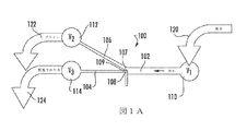
淡水化ユニット(100)を備えた実施例の装置を、図1Aに概略図に図示する。淡水化ユニットは、希薄出口チャネル(104)及び濃縮出口チャネル(106)と流体的に接続された入口チャネル(102)を含む。希薄出口チャネル(104)及び濃縮出口チャネル(106)は、交点(107)において入口チャネル(102)から分岐する。電極(108)が、交点(107)に近接して位置付けられる。電極(108)は、装置の運転中、電極に及びその下流にイオン枯渇領域(109)を形成するように構成され、その結果、交点付近に電場勾配が形成される。実施例の装置は、入口チャネル(102)の上流末端と流体的に接続された流体容器(110)、希薄出口チャネル(104)の下流末端と流体的に接続された流体容器(114)、及び濃縮出口チャネル(106)の下流末端と流体的に接続された流体容器(112)をさらに含む。 An example apparatus with a desalination unit (100) is illustrated schematically in FIG. 1A. The desalination unit includes an inlet channel (102) fluidly connected with a lean outlet channel (104) and a concentrating outlet channel (106). The lean outlet channel (104) and the concentrated outlet channel (106) branch off from the inlet channel (102) at the intersection (107). An electrode (108) is positioned proximate to the intersection (107). The electrode (108) is configured to form an ion depletion region (109) in and downstream of the electrode during operation of the device, resulting in an electric field gradient near the intersection. An example apparatus includes a fluid container (110) fluidly connected to the upstream end of the inlet channel (102), a fluid container (114) fluidly connected to the downstream end of the lean outlet channel (104), and It further includes a fluid container (112) fluidly connected to the downstream end of the concentration outlet channel (106).
淡水化ユニット(100)におけるマイクロ流体チャネル(例えば、入口チャネル(102)、希薄出口チャネル(104)及び濃縮出口チャネル(106))の寸法は、いくつかの要因を考慮して、単独でかつ/または組み合わせにおいて選択できる。これらの要因には、淡水化ユニットにおけるマイクロ流体チャネルに対する電極のサイズ及び位置、装置の所望の流量、装置を使用して処理される塩水の塩分、並びに所望の塩分低減の程度が含まれる。 The dimensions of the microfluidic channels (eg, inlet channel (102), lean outlet channel (104) and enrichment outlet channel (106)) in the desalination unit (100) are independent and / or take into account several factors. Or it can choose in combination. These factors include the size and location of the electrodes relative to the microfluidic channel in the desalination unit, the desired flow rate of the device, the salinity of the salt water treated using the device, and the desired degree of salinity reduction.
場合によっては、入口チャネル(102)、希薄出口チャネル(104)及び濃縮出口チャネル(106)の寸法は、希薄出口チャネルの断面積と濃縮出口チャネルの断面積との合計が、入口チャネルの断面積と実質的に等しくなるように選択される。この文脈において、実質的に等しいとは、希薄出口チャネルの断面積と濃縮出口チャネルの断面積との合計が、例えば、入口チャネルの断面積の15%以内(例えば、入口チャネルの断面積の10%以内、または入口チャネルの断面積の5%以内)にあることを意味し得る。いくつかの実施形態では、希薄出口チャネルと濃縮出口チャネルとは、実質的に同等の断面寸法を有する。これは、希薄出口チャネルの高さ及び幅が、濃縮出口チャネルの高さ及び幅と実質的に同等(例えば、15%以内、10%以内または5%以内)であることを意味する。 In some cases, the dimensions of the inlet channel (102), lean outlet channel (104), and enrichment outlet channel (106) are such that the sum of the cross sectional area of the lean outlet channel and the cross section of the enrichment outlet channel is the cross sectional area of the inlet channel. To be substantially equal. In this context, substantially equal means that the sum of the cross-sectional area of the lean outlet channel and the cross-sectional area of the enriched outlet channel is, for example, within 15% of the cross-sectional area of the inlet channel (eg, 10% of the cross-sectional area of the inlet channel). % Or within 5% of the cross-sectional area of the inlet channel. In some embodiments, the lean outlet channel and the concentrated outlet channel have substantially equivalent cross-sectional dimensions. This means that the height and width of the lean outlet channel is substantially equivalent to the height and width of the concentrated outlet channel (eg, within 15%, within 10% or within 5%).
淡水化ユニット(100)におけるマイクロ流体チャネル(例えば、入口チャネル(102)、希薄出口チャネル(104)及び濃縮出口チャネル(106))の寸法は、さまざまな断面形状を有するように製造できる。いくつかの実施形態では、淡水化ユニットにおけるマイクロ流体チャネル(例えば、入口チャネル、希薄出口チャネル及び濃縮出口チャネル)は、実質的に正方形または矩形の断面形状を有する。 The dimensions of the microfluidic channels (eg, the inlet channel (102), the lean outlet channel (104), and the concentrated outlet channel (106)) in the desalination unit (100) can be manufactured to have various cross-sectional shapes. In some embodiments, the microfluidic channels (eg, inlet channel, lean outlet channel and enrichment outlet channel) in the desalination unit have a substantially square or rectangular cross-sectional shape.
いくつかの実施形態では、入口チャネル(102)の幅は、約1000μm以下(例えば、約900μm以下、約800μm以下、約750μm以下、約700μm以下、約600μm以下、約500μm以下、約400μm以下、約300μm以下、約250μm以下、約200μm以下、約150μm以下、約100μm以下、約75μm以下、または約50μm以下)である。いくつかの実施形態では、入口チャネル(102)の幅は、少なくとも約1μm(例えば、少なくとも約5μm、少なくとも約10μm、少なくとも約15μm、少なくとも約20μm、少なくとも約25μm、少なくとも約50μm、少なくとも約75μm、少なくとも約100μm、少なくとも約150μm、少なくとも約200μm、少なくとも約250μm、少なくとも約300μm、少なくとも約400μm、少なくとも約500μm、少なくとも約600μm、少なくとも約700μm、少なくとも約750μm、少なくとも約800μm、少なくとも約900μm、または少なくとも約1000μm)である。 In some embodiments, the width of the inlet channel (102) is about 1000 μm or less (eg, about 900 μm or less, about 800 μm or less, about 750 μm or less, about 700 μm or less, about 600 μm or less, about 500 μm or less, about 400 μm or less, About 300 μm or less, about 250 μm or less, about 200 μm or less, about 150 μm or less, about 100 μm or less, about 75 μm or less, or about 50 μm or less). In some embodiments, the width of the inlet channel (102) is at least about 1 μm (eg, at least about 5 μm, at least about 10 μm, at least about 15 μm, at least about 20 μm, at least about 25 μm, at least about 50 μm, at least about 75 μm, At least about 100 μm, at least about 150 μm, at least about 200 μm, at least about 250 μm, at least about 300 μm, at least about 400 μm, at least about 500 μm, at least about 600 μm, at least about 700 μm, at least about 750 μm, at least about 800 μm, at least about 900 μm, or at least About 1000 μm).
入口チャネル(102)の幅は、前述の任意の最小寸法から任意の最大寸法までの範囲であってもよい。例えば、入口チャネル(102)の幅は、約1000μmから約1μmまでの範囲(例えば、約750μmから約5μm、約500μmから約10μm、約250μmから約20μm、または約150μmから約25μm)であってもよい。 The width of the inlet channel (102) may range from any minimum dimension described above to any maximum dimension. For example, the width of the inlet channel (102) ranges from about 1000 μm to about 1 μm (eg, from about 750 μm to about 5 μm, from about 500 μm to about 10 μm, from about 250 μm to about 20 μm, or from about 150 μm to about 25 μm) Also good.
いくつかの実施形態では、入口チャネル(102)の高さは、約50μm以下(例えば、約45μm以下、約40μm以下、約35μm以下、約30μm以下、約25μm以下、約20μm以下、約15μm以下、約10μm以下、約9μm以下、約8μm以下、約7.5μm以下、約7μm以下、約6μm以下、約5μm以下、約4μm以下、約3μm以下、約2.5μm以下、または約2μm以下)である。いくつかの実施形態では、入口チャネル(102)の高さは、少なくとも約1μm(例えば、少なくとも約2μm、少なくとも約2.5μm、少なくとも約3μm、少なくとも約4μm、少なくとも約5μm、少なくとも約6μm、少なくとも約7μm、少なくとも約7.5μm、少なくとも約8μm、少なくとも約9μm、少なくとも約10μm、少なくとも約15μm、少なくとも約20μm、少なくとも約25μm、少なくとも約30μm、少なくとも約35μm、少なくとも約40μm、または少なくとも約45μm)である。 In some embodiments, the height of the inlet channel (102) is about 50 μm or less (eg, about 45 μm or less, about 40 μm or less, about 35 μm or less, about 30 μm or less, about 25 μm or less, about 20 μm or less, about 15 μm or less. About 10 μm or less, about 9 μm or less, about 8 μm or less, about 7.5 μm or less, about 7 μm or less, about 6 μm or less, about 5 μm or less, about 4 μm or less, about 3 μm or less, about 2.5 μm or less, or about 2 μm or less) It is. In some embodiments, the height of the inlet channel (102) is at least about 1 μm (eg, at least about 2 μm, at least about 2.5 μm, at least about 3 μm, at least about 4 μm, at least about 5 μm, at least about 6 μm, at least About 7 μm, at least about 7.5 μm, at least about 8 μm, at least about 9 μm, at least about 10 μm, at least about 15 μm, at least about 20 μm, at least about 25 μm, at least about 30 μm, at least about 35 μm, at least about 40 μm, or at least about 45 μm) It is.
入口チャネル(102)の高さは、前述の任意の最小寸法から任意の最大寸法までの範囲であってもよい。例えば、入口チャネル(102)の高さは、約50μmから約1μmまでの範囲(例えば、約45μmから約1μm、約40μmから約1μm、約35μmから約1μm、約30μmから約1μm、約25μmから約1μm、または約20μmから約1μm)であってもよい。 The height of the inlet channel (102) may range from any minimum dimension described above to any maximum dimension. For example, the height of the inlet channel (102) ranges from about 50 μm to about 1 μm (eg, from about 45 μm to about 1 μm, from about 40 μm to about 1 μm, from about 35 μm to about 1 μm, from about 30 μm to about 1 μm, from about 25 μm About 1 μm, or about 20 μm to about 1 μm).
いくつかの実施形態では、希薄出口チャネル(104)の幅は、約500μm以下(例えば、約450μm以下、約400μm以下、約350μm以下、約300μm以下、約250μm以下、約200μm以下、約150μm以下、約125μm以下、約100μm以下、約75μm以下、約50μm以下、約25μm以下、約20μm以下、約15μm以下、約10μm以下、約5μm以下、または約1μm以下)である。いくつかの実施形態では、希薄出口チャネル(104)の幅は、少なくとも約0.5μm(例えば、少なくとも約1μm、少なくとも約2.5μm、少なくとも約5μm、少なくとも約10μm、少なくとも約15μm、少なくとも約20μm、少なくとも約25μm、少なくとも約50μm、少なくとも約75μm、少なくとも約100μm、少なくとも約150μm、少なくとも約200μm、少なくとも約250μm、少なくとも約300μm、少なくとも約400μm、または少なくとも約450μm)である。 In some embodiments, the width of the lean exit channel (104) is about 500 μm or less (eg, about 450 μm or less, about 400 μm or less, about 350 μm or less, about 300 μm or less, about 250 μm or less, about 200 μm or less, about 150 μm or less. About 125 μm or less, about 100 μm or less, about 75 μm or less, about 50 μm or less, about 25 μm or less, about 20 μm or less, about 15 μm or less, about 10 μm or less, about 5 μm or less, or about 1 μm or less. In some embodiments, the width of the lean exit channel (104) is at least about 0.5 μm (eg, at least about 1 μm, at least about 2.5 μm, at least about 5 μm, at least about 10 μm, at least about 15 μm, at least about 20 μm). At least about 25 μm, at least about 50 μm, at least about 75 μm, at least about 100 μm, at least about 150 μm, at least about 200 μm, at least about 250 μm, at least about 300 μm, at least about 400 μm, or at least about 450 μm).
希薄出口チャネル(104)の幅は、前述の任意の最小寸法から任意の最大寸法までの範囲であってもよい。例えば、希薄出口チャネル(104)の幅は、約500μmから約0.5μmまでの範囲(例えば、約400μmから約1μm、約250μmから約1μm、約150μmから約5μm、または約80μmから約10μm)であってもよい。 The width of the lean exit channel (104) may range from any of the aforementioned minimum dimensions to any maximum dimension. For example, the width of the lean outlet channel (104) ranges from about 500 μm to about 0.5 μm (eg, about 400 μm to about 1 μm, about 250 μm to about 1 μm, about 150 μm to about 5 μm, or about 80 μm to about 10 μm). It may be.
いくつかの実施形態では、希薄出口チャネル(104)の高さは、約50μm以下(例えば、約45μm以下、約40μm以下、約35μm以下、約30μm以下、約25μm以下、約20μm以下、約15μm以下、約10μm以下、約9μm以下、約8μm以下、約7.5μm以下、約7μm以下、約6μm以下、約5μm以下、約4μm以下、約3μm以下、約2.5μm以下、または約2μm以下)である。いくつかの実施形態では、希薄出口チャネル(104)の高さは、少なくとも約1μm(例えば、少なくとも約2μm、少なくとも約2.5μm、少なくとも約3μm、少なくとも約4μm、少なくとも約5μm、少なくとも約6μm、少なくとも約7μm、少なくとも約7.5μm、少なくとも約8μm、少なくとも約9μm、少なくとも約10μm、少なくとも約15μm、少なくとも約20μm、少なくとも約25μm、少なくとも約30μm、少なくとも約35μm、少なくとも約40μm、または少なくとも約45μm)である。 In some embodiments, the height of the lean outlet channel (104) is about 50 μm or less (eg, about 45 μm or less, about 40 μm or less, about 35 μm or less, about 30 μm or less, about 25 μm or less, about 20 μm or less, about 15 μm). Below, about 10 μm or less, about 9 μm or less, about 8 μm or less, about 7.5 μm or less, about 7 μm or less, about 6 μm or less, about 5 μm or less, about 4 μm or less, about 3 μm or less, about 2.5 μm or less, or about 2 μm or less ). In some embodiments, the height of the lean exit channel (104) is at least about 1 μm (eg, at least about 2 μm, at least about 2.5 μm, at least about 3 μm, at least about 4 μm, at least about 5 μm, at least about 6 μm, At least about 7 μm, at least about 7.5 μm, at least about 8 μm, at least about 9 μm, at least about 10 μm, at least about 15 μm, at least about 20 μm, at least about 25 μm, at least about 30 μm, at least about 35 μm, at least about 40 μm, or at least about 45 μm ).
希薄出口チャネル(104)の高さは、前述の任意の最小寸法から任意の最大寸法までの範囲であってもよい。例えば、希薄出口チャネル(104)の高さは、約50μmから約1μmまでの範囲(例えば、約45μmから約1μm、約40μmから約1μm、約35μmから約1μm、約30μmから約1μm、約25μmから約1μm、または約20μmから約1μm)であってもよい。 The height of the lean exit channel (104) may range from any of the aforementioned minimum dimensions to any maximum dimension. For example, the height of the lean outlet channel (104) ranges from about 50 μm to about 1 μm (eg, about 45 μm to about 1 μm, about 40 μm to about 1 μm, about 35 μm to about 1 μm, about 30 μm to about 1 μm, about 25 μm To about 1 μm, or about 20 μm to about 1 μm).
いくつかの実施形態では、濃縮出口チャネル(106)の幅は、約500μm以下(例えば、約450μm以下、約400μm以下、約350μm以下、約300μm以下、約250μm以下、約200μm以下、約150μm以下、約125μm以下、約100μm以下、約75μm以下、約50μm以下、約25μm以下、約20μm以下、約15μm以下、約10μm以下、約5μm以下、または約1μm以下)である。いくつかの実施形態では、濃縮出口チャネル(106)の幅は、少なくとも約0.5μm(例えば、少なくとも約1μm、少なくとも約2.5μm、少なくとも約5μm、少なくとも約10μm、少なくとも約15μm、少なくとも約20μm、少なくとも約25μm、少なくとも約50μm、少なくとも約75μm、少なくとも約100μm、少なくとも約150μm、少なくとも約200μm、少なくとも約250μm、少なくとも約300μm、少なくとも約400μm、または少なくとも約450μm)である。 In some embodiments, the width of the concentration outlet channel (106) is about 500 μm or less (eg, about 450 μm or less, about 400 μm or less, about 350 μm or less, about 300 μm or less, about 250 μm or less, about 200 μm or less, about 150 μm or less. About 125 μm or less, about 100 μm or less, about 75 μm or less, about 50 μm or less, about 25 μm or less, about 20 μm or less, about 15 μm or less, about 10 μm or less, about 5 μm or less, or about 1 μm or less. In some embodiments, the width of the concentration outlet channel (106) is at least about 0.5 μm (eg, at least about 1 μm, at least about 2.5 μm, at least about 5 μm, at least about 10 μm, at least about 15 μm, at least about 20 μm). At least about 25 μm, at least about 50 μm, at least about 75 μm, at least about 100 μm, at least about 150 μm, at least about 200 μm, at least about 250 μm, at least about 300 μm, at least about 400 μm, or at least about 450 μm).
濃縮出口チャネル(106)の幅は、前述の任意の最小寸法から任意の最大寸法までの範囲であってもよい。例えば、濃縮出口チャネル(106)の幅は、約500μmから約0.5μmまでの範囲(例えば、約400μmから約1μm、約250μmから約1μm、約150μmから約5μm、または約80μmから約10μm)であってもよい。 The width of the concentration outlet channel (106) may range from any of the aforementioned minimum dimensions to any maximum dimension. For example, the width of the concentration outlet channel (106) ranges from about 500 μm to about 0.5 μm (eg, about 400 μm to about 1 μm, about 250 μm to about 1 μm, about 150 μm to about 5 μm, or about 80 μm to about 10 μm). It may be.
いくつかの実施形態では、濃縮出口チャネル(106)の高さは、約50μm以下(例えば、約45μm以下、約40μm以下、約35μm以下、約30μm以下、約25μm以下、約20μm以下、約15μm以下、約10μm以下、約9μm以下、約8μm以下、約7.5μm以下、約7μm以下、約6μm以下、約5μm以下、約4μm以下、約3μm以下、約2.5μm以下、または約2μm以下)である。いくつかの実施形態では、濃縮出口チャネル(106)の高さは、少なくとも約1μm(例えば、少なくとも約2μm、少なくとも約2.5μm、少なくとも約3μm、少なくとも約4μm、少なくとも約5μm、少なくとも約6μm、少なくとも約7μm、少なくとも約7.5μm、少なくとも約8μm、少なくとも約9μm、少なくとも約10μm、少なくとも約15μm、少なくとも約20μm、少なくとも約25μm、少なくとも約30μm、少なくとも約35μm、少なくとも約40μm、または少なくとも約45μm)である。 In some embodiments, the height of the concentration outlet channel (106) is about 50 μm or less (eg, about 45 μm or less, about 40 μm or less, about 35 μm or less, about 30 μm or less, about 25 μm or less, about 20 μm or less, about 15 μm). Below, about 10 μm or less, about 9 μm or less, about 8 μm or less, about 7.5 μm or less, about 7 μm or less, about 6 μm or less, about 5 μm or less, about 4 μm or less, about 3 μm or less, about 2.5 μm or less, or about 2 μm or less ). In some embodiments, the height of the concentration outlet channel (106) is at least about 1 μm (eg, at least about 2 μm, at least about 2.5 μm, at least about 3 μm, at least about 4 μm, at least about 5 μm, at least about 6 μm, At least about 7 μm, at least about 7.5 μm, at least about 8 μm, at least about 9 μm, at least about 10 μm, at least about 15 μm, at least about 20 μm, at least about 25 μm, at least about 30 μm, at least about 35 μm, at least about 40 μm, or at least about 45 μm ).
濃縮出口チャネル(106)の高さは、前述の任意の最小寸法から任意の最大寸法までの範囲であってもよい。例えば、濃縮出口チャネル(106)の高さは、約50μmから約1μmまでの範囲(例えば、約45μmから約1μm、約40μmから約1μm、約35μmから約1μm、約30μmから約1μm、約25μmから約1μm、または約20μmから約1μm)であってもよい。 The height of the concentration outlet channel (106) may range from any of the aforementioned minimum dimensions to any maximum dimension. For example, the height of the concentration outlet channel (106) ranges from about 50 μm to about 1 μm (eg, about 45 μm to about 1 μm, about 40 μm to about 1 μm, about 35 μm to about 1 μm, about 30 μm to about 1 μm, about 25 μm To about 1 μm, or about 20 μm to about 1 μm).
淡水化ユニット(100)におけるマイクロ流体チャネル(例えば、入口チャネル(102)、希薄出口チャネル(104)及び濃縮出口チャネル(106))の長さは、変えることができる。淡水化ユニットにおけるマイクロ流体チャネルの長さは、装置の全体設計及び他の運転上のいくつかの検討事項を考慮して個別に選択できる。いくつかの実施形態では、入口チャネル(102)、希薄出口チャネル(104)及び濃縮出口チャネル(106)の各々の長さは、少なくとも約0.1cm(例えば、少なくとも約0.2cm、少なくとも約0.3cm、少なくとも約0.4cm、少なくとも約0.5cm、少なくとも約0.6cm、少なくとも約0.7cm、少なくとも約0.8cm、少なくとも約0.9cm、少なくとも約1cm、少なくとも約2cm、少なくとも約2.5cm、少なくとも約3cm、少なくとも約4cm、少なくとも約5cm、またはそれよりも長い)である。淡水化ユニットにおけるマイクロ流体チャネルは、形状が実質的に線形であってもよいし、流体流路の長さに沿った一つ以上の非線形領域(例えば、湾曲領域、らせん領域、角のある領域、またはそれらの組み合わせ)を有してもよい。 The length of the microfluidic channels (eg, inlet channel (102), lean outlet channel (104) and enrichment outlet channel (106)) in the desalination unit (100) can vary. The length of the microfluidic channel in the desalination unit can be selected individually taking into account the overall design of the device and several other operational considerations. In some embodiments, the length of each of the inlet channel (102), lean outlet channel (104) and enrichment outlet channel (106) is at least about 0.1 cm (eg, at least about 0.2 cm, at least about 0). .3 cm, at least about 0.4 cm, at least about 0.5 cm, at least about 0.6 cm, at least about 0.7 cm, at least about 0.8 cm, at least about 0.9 cm, at least about 1 cm, at least about 2 cm, at least about 2 .5 cm, at least about 3 cm, at least about 4 cm, at least about 5 cm, or longer). The microfluidic channel in the desalination unit may be substantially linear in shape and may include one or more non-linear regions (eg, curved regions, spiral regions, angular regions) along the length of the fluid flow path. Or a combination thereof).
図1Aを再び参照すると、希薄出口チャネル(104)及び濃縮出口チャネル(106)は、交点(107)において入口チャネル(102)から分岐する。交点における希薄出口チャネル(104)及び濃縮出口チャネル(106)の互いに対する向きは、変えることができる。装置において希薄出口チャネル(104)と濃縮出口チャネル(106)との間に形成される角度は、いくつかのパラメータを考慮して選択できる。これらのパラメータには、淡水化ユニットにおけるマイクロ流体チャネルに対する電極のサイズ及び位置、装置の所望の流量、装置を使用して処理される塩水の塩分、並びに所望の塩分低減程度が含まれる。 Referring again to FIG. 1A, the lean outlet channel (104) and the concentrated outlet channel (106) branch off from the inlet channel (102) at the intersection (107). The orientation of the lean outlet channel (104) and the concentrated outlet channel (106) relative to each other at the intersection can be varied. The angle formed between the lean outlet channel (104) and the concentrated outlet channel (106) in the device can be selected taking into account several parameters. These parameters include the size and location of the electrodes relative to the microfluidic channel in the desalination unit, the desired flow rate of the device, the salinity of the salt water treated using the device, and the desired degree of salinity reduction.
いくつかの場合では、交点(107)における希薄出口チャネル(104)と濃縮出口チャネル(106)との間に形成される角度は、約90度以下(例えば、約85度以下、約80度以下、約75度以下、約70度以下、約65度以下、約60度以下、約55度以下、約50度以下、約45度以下、約40度以下、約35度以下、約30度以下、約25度以下、約20度以下、約15度以下、またはそれ以下)である。 In some cases, the angle formed between the lean outlet channel (104) and the concentrated outlet channel (106) at the intersection (107) is about 90 degrees or less (eg, about 85 degrees or less, about 80 degrees or less). About 75 degrees or less, about 70 degrees or less, about 65 degrees or less, about 60 degrees or less, about 55 degrees or less, about 50 degrees or less, about 45 degrees or less, about 40 degrees or less, about 35 degrees or less, about 30 degrees or less About 25 degrees or less, about 20 degrees or less, about 15 degrees or less, or less).
電極(108)は、金属(例えば、金、プラチナまたはチタン)、金属合金、金属酸化物または導電性カーボンなどの任意の適切な導体材料から製造できる。電極(108)は、淡水化ユニット(100)と電気化学的に接触するように構成される。これは、電極(108)が、淡水化ユニットのマイクロ流体チャネル内に存在する溶液の一つ以上の成分とのファラデー反応に関与できることを意味する。例えば、電極(108)は、電極の表面が淡水化ユニットのマイクロ流体チャネル内に存在する流体と直接接触するように構成できる。装置は、電極(108)が装置の運転中に陽極、陰極または陽極及び陰極のいずれかとして機能できるように構成できる。 The electrode (108) can be made from any suitable conductive material, such as a metal (eg, gold, platinum or titanium), a metal alloy, a metal oxide or conductive carbon. The electrode (108) is configured to be in electrochemical contact with the desalination unit (100). This means that the electrode (108) can participate in a Faraday reaction with one or more components of the solution present in the microfluidic channel of the desalination unit. For example, the electrode (108) can be configured such that the surface of the electrode is in direct contact with the fluid present in the microfluidic channel of the desalination unit. The device can be configured such that the electrode (108) can function as either an anode, a cathode, or an anode and a cathode during operation of the device.
淡水化ユニットに対する電極(108)の位置及び寸法は、いくつかの要因を考慮して選択できる。これらの要因には、淡水化ユニットにおけるマイクロ流体チャネルのサイズ及び構成、装置の所望の流量、装置を使用して処理される塩水の塩分、並びに所望の塩分低減程度が含まれる。電極(108)は、電極(108)を装置内に組み込み、かつイオンを、入口チャネル(102)を通して濃縮出口チャネル(106)に優先的に流すのに適した電場勾配の形成に対応できる限り、さまざまな二次元または三次元形状を有することができる。ある特定の実施形態では、電極(108)は、入口チャネル(102)の底と実質的に同一平面上にある導電面(例えば、線形、矩形パッドまたは正方形パッド)であり、交点(107)の近接において入口チャネルの底に組み込まれる。他の実施形態では、電極(108)は、交点(107)の近接において入口チャネルの底にまたはその内部に製造された導電面(例えば、線形、矩形パッドまたは正方形パッド)であり、入口チャネルの底から入口チャネル内に延伸する。これらの実施形態では、電極は、入口チャネルの底から、入口チャネルの底から最大距離に位置付けられた、入口チャネル内の電極の表面または縁部までの距離として測定された高さを有すると言うことができる。 The position and dimensions of the electrode (108) relative to the desalination unit can be selected considering several factors. These factors include the size and configuration of the microfluidic channels in the desalination unit, the desired flow rate of the device, the salinity of the salt water treated using the device, and the desired degree of salinity reduction. As long as the electrode (108) can accommodate the formation of an electric field gradient suitable for incorporating the electrode (108) into the device and allowing ions to flow preferentially through the inlet channel (102) to the concentrated outlet channel (106). It can have various two-dimensional or three-dimensional shapes. In certain embodiments, the electrode (108) is a conductive surface (eg, linear, rectangular or square pad) that is substantially coplanar with the bottom of the inlet channel (102) and at the intersection (107). Proximately integrated into the bottom of the inlet channel. In other embodiments, the electrode (108) is a conductive surface (eg, a linear, rectangular or square pad) fabricated at or in the bottom of the inlet channel in the vicinity of the intersection (107) Extends from the bottom into the inlet channel. In these embodiments, the electrode is said to have a height measured as the distance from the bottom of the inlet channel to the surface or edge of the electrode in the inlet channel, located at the maximum distance from the bottom of the inlet channel. be able to.
図1Aを再び参照すると、電極(108)は、電極(108)に及びその下流にイオン枯渇領域(109)を形成し、装置の運転中に希薄出口チャネル(104)内に延伸するように、交点(107)に近接して位置付けることができる。イオン枯渇領域(109)は、濃縮出口チャネル(106)の一部分内に任意的に延伸することができる。いくつかの実施形態では、電極(108)は、希薄出口チャネル(104)の開口の上流における入口チャネル(102)の底内に位置付けられる。 Referring again to FIG. 1A, the electrode (108) forms an ion depletion region (109) at and downstream of the electrode (108) and extends into the lean exit channel (104) during operation of the device. It can be positioned close to the intersection (107). The ion depletion region (109) can optionally extend into a portion of the enrichment outlet channel (106). In some embodiments, the electrode (108) is positioned in the bottom of the inlet channel (102) upstream of the opening of the lean outlet channel (104).
例示として、図1Bは、図1Aに示す装置の交点(107)の拡大図を図示する。電極(108)が、入口チャネル(102)の底内に位置付けられる。淡水化ユニットと電気化学的に接触する電極(108)の表面は、希薄出口チャネル(104)の開口のおおよそ±50μm上流または下流(希薄出口チャネルの開口から電極の下流縁部までの距離として測定された、130)に位置付けられる。 By way of example, FIG. 1B illustrates an enlarged view of the intersection (107) of the apparatus shown in FIG. 1A. An electrode (108) is positioned in the bottom of the inlet channel (102). The surface of the electrode (108) in electrochemical contact with the desalination unit is measured approximately ± 50 μm upstream or downstream of the opening of the lean outlet channel (104) (distance from the opening of the lean outlet channel to the downstream edge of the electrode). 130).
ある特定の実施形態では、淡水化ユニットと電気化学的に接触する電極(108)の表面は、希薄出口チャネル(104)の開口の上流、かつ希薄出口チャネルの開口の約500μm以内(例えば、約400μm以内、約300μm以内、約250μm以内、約200μm以内、約150μm以内、約100μm以内、約90μm以内、約80μm以内、約75μm以内、約70μm以内、約60μm以内、約50マイクロ以内、約40μm以内、約30μm以内、約25μm以内、約20μm以内、または約10μm以内)に位置付けられる。 In certain embodiments, the surface of the electrode (108) in electrochemical contact with the desalination unit is upstream of the opening of the lean outlet channel (104) and within about 500 μm of the opening of the lean outlet channel (eg, about Within 400 μm, within approximately 300 μm, within approximately 250 μm, within approximately 200 μm, within approximately 150 μm, within approximately 100 μm, within approximately 90 μm, within approximately 80 μm, within approximately 75 μm, within approximately 70 μm, within approximately 60 μm, within approximately 50 μm, within approximately 40 μm Within about 30 μm, within about 25 μm, within about 20 μm, or within about 10 μm).
いくつかの実施形態では、淡水化ユニットと電気化学的に接触する電極(108)の表面は、希薄出口チャネル(104)の開口の下流に、かつ希薄出口チャネルの開口の約100μm以内(例えば、約90μm以内、約80μm以内、約75μm以内、約70μm以内、約60μm以内、約50μm以内、約40μm以内、約30μm以内、約25μm以内、約20μm以内、約10μm以内、または約5μm以内)に位置付けられる。淡水化ユニットと電気化学的に接触する電極(108)の表面が希薄出口チャネル(104)の開口の下流に位置付けられる場合には、電極の長さは、(以下に論じるように)淡水化ユニットと電気化学的に接触する電極(108)の少なくとも一部が、希薄出口チャネル(104)の開口を越えて入口チャネル内に延伸する(すなわち、電極の一部が希薄出口チャネルの上流位置になければならない)のに十分な長さでなければならない。 In some embodiments, the surface of the electrode (108) in electrochemical contact with the desalination unit is downstream of the opening of the lean outlet channel (104) and within about 100 μm of the opening of the lean outlet channel (eg, Within about 90 μm, within about 80 μm, within about 75 μm, within about 70 μm, within about 60 μm, within about 50 μm, within about 40 μm, within about 30 μm, within about 25 μm, within about 20 μm, within about 10 μm, or within about 5 μm) Positioned. If the surface of the electrode (108) in electrochemical contact with the desalination unit is positioned downstream of the opening of the lean outlet channel (104), the length of the electrode is (as discussed below) the desalination unit. At least a portion of the electrode (108) in electrochemical contact with the electrode extends beyond the opening of the lean outlet channel (104) into the inlet channel (ie, a portion of the electrode must be upstream of the lean outlet channel). Must be long enough).
再び図1Bを参照すると、淡水化ユニットと電気化学的に接触する電極(108)の表面は、幅(入口チャネルを流れる流体の方向と垂直の軸に沿う、電極の表面の一方の側面から他方の側面までの距離として測定される、132)、及び長さ(入口チャネルを流れる流体の方向と平行の軸に沿う、電極の表面の一方の側面から他方の側面までの距離として測定される、134)を有することができる。例示として、図1Bの実施例の装置では、淡水化ユニットと電気化学的に接触する電極(108)の表面の幅(132)は、希薄出口チャネル(104)の幅(50μm)とほぼ等しく、長さ(134)は約100μmである。 Referring again to FIG. 1B, the surface of the electrode (108) in electrochemical contact with the desalination unit has a width (from one side of the surface of the electrode along the axis perpendicular to the direction of the fluid flowing through the inlet channel to the other. 132), and the length (measured as the distance from one side of the electrode surface to the other side along an axis parallel to the direction of the fluid flowing through the inlet channel). 134). Illustratively, in the example apparatus of FIG. 1B, the width (132) of the surface of the electrode (108) in electrochemical contact with the desalination unit is approximately equal to the width (50 μm) of the lean outlet channel (104); The length (134) is about 100 μm.
いくつかの実施形態では、淡水化ユニットと電気化学的に接触する電極(108)の表面の幅(132)は、希薄出口チャネル(104)の幅の少なくとも約50%(例えば、希薄出口チャネルの幅の少なくとも約60%、希薄出口チャネルの幅の少なくとも約70%、希薄出口チャネルの幅の少なくとも約75%、希薄出口チャネルの幅の少なくとも約80%、希薄出口チャネルの幅の少なくとも約90%、希薄出口チャネルの幅の少なくとも約90%、少なくとも希薄出口チャネルの幅、希薄出口チャネルの幅の少なくとも約105%、または希薄出口チャネルの幅の少なくとも約110%)である。いくつかの実施形態では、淡水化ユニットと電気化学的に接触する電極(108)の表面の幅(132)は、希薄出口チャネル(104)の幅の約150%未満(例えば、希薄出口チャネルの幅の約140%未満、希薄出口チャネルの幅の約130%未満、希薄出口チャネルの幅の約125%未満、希薄出口チャネルの幅の約120%未満、希薄出口チャネルの幅の約110%未満、希薄出口チャネルの幅の約105%未満、または希薄出口チャネルの幅未満)である。 In some embodiments, the width (132) of the surface of the electrode (108) in electrochemical contact with the desalination unit is at least about 50% of the width of the lean outlet channel (104) (eg, of the lean outlet channel). At least about 60% of the width, at least about 70% of the width of the lean exit channel, at least about 75% of the width of the lean exit channel, at least about 80% of the width of the lean exit channel, at least about 90% of the width of the lean exit channel At least about 90% of the width of the lean exit channel, at least the width of the lean exit channel, at least about 105% of the width of the lean exit channel, or at least about 110% of the width of the lean exit channel). In some embodiments, the width (132) of the surface of the electrode (108) in electrochemical contact with the desalination unit is less than about 150% of the width of the lean outlet channel (104) (eg, of the lean outlet channel). Less than about 140% of the width, less than about 130% of the width of the lean exit channel, less than about 125% of the width of the lean exit channel, less than about 120% of the width of the lean exit channel, less than about 110% of the width of the lean exit channel Less than about 105% of the width of the lean exit channel, or less than the width of the lean exit channel).
淡水化ユニットと電気化学的に接触する電極(108)の表面の幅(132)は、前述の任意の最小寸法から任意の最大寸法までの範囲であってもよい。例えば、淡水化ユニットと電気化学的に接触する電極(108)の表面の幅(132)は、希薄出口チャネル(104)の幅の約50%から希薄出口チャネルの幅の約150%までの範囲(例えば、希薄出口チャネルの幅の約75%から希薄出口チャネルの幅の約125%、希薄出口チャネルの幅の約90%から希薄出口チャネルの幅の約110%、または希薄出口チャネルの幅の約95%から希薄出口チャネルの幅の約105%)であってもよい。ある特定の実施形態では、淡水化ユニットと電気化学的に接触する電極(108)の表面の幅(132)は、希薄出口チャネル(104)の幅とほぼ等しい。 The surface width (132) of the electrode (108) in electrochemical contact with the desalination unit may range from any of the aforementioned minimum dimensions to any maximum dimension. For example, the width (132) of the surface of the electrode (108) in electrochemical contact with the desalination unit ranges from about 50% of the width of the lean outlet channel (104) to about 150% of the width of the lean outlet channel. (E.g., from about 75% of the width of the lean exit channel to about 125% of the width of the lean exit channel, from about 90% of the width of the lean exit channel to about 110% of the width of the lean exit channel, or from the width of the lean exit channel From about 95% to about 105% of the width of the lean exit channel). In certain embodiments, the width (132) of the surface of the electrode (108) in electrochemical contact with the desalination unit is approximately equal to the width of the lean outlet channel (104).
いくつかの実施形態では、淡水化ユニットと電気化学的に接触する電極(108)の表面の幅(132)は、入口チャネル(102)の幅の少なくとも約25%(例えば、入口チャネルの幅の少なくとも約30%、入口チャネルの幅の少なくとも約40%、入口チャネルの幅の少なくとも約45%、入口チャネルの幅の少なくとも約50%、入口チャネルの幅の少なくとも約55%、または入口チャネルの幅の少なくとも約60%)である。いくつかの実施形態では、淡水化ユニットと電気化学的に接触する電極(108)の表面の幅(132)は、入口チャネル(102)の幅の約75%未満(例えば、入口チャネルの幅の約60%未満、入口チャネルの幅の約55%未満、入口チャネルの幅の約50%未満、入口チャネルの幅の約45%未満、または入口チャネルの幅の約40%未満)である。 In some embodiments, the width (132) of the surface of the electrode (108) in electrochemical contact with the desalination unit is at least about 25% of the width of the inlet channel (102) (eg, of the width of the inlet channel). At least about 30%, at least about 40% of the width of the inlet channel, at least about 45% of the width of the inlet channel, at least about 50% of the width of the inlet channel, at least about 55% of the width of the inlet channel, or the width of the inlet channel At least about 60%). In some embodiments, the width (132) of the surface of the electrode (108) in electrochemical contact with the desalination unit is less than about 75% of the width of the inlet channel (102) (eg, of the width of the inlet channel). Less than about 60%, less than about 55% of the width of the inlet channel, less than about 50% of the width of the inlet channel, less than about 45% of the width of the inlet channel, or less than about 40% of the width of the inlet channel).
淡水化ユニットと電気化学的に接触する電極(108)の表面の幅(132)は、前述の任意の最小寸法から任意の最大寸法までの範囲であってもよい。例えば、淡水化ユニットと電気化学的に接触する電極(108)の表面の幅(132)は、入口チャネル(102)の幅の約25%から入口チャネルの幅の約75%の範囲(例えば、希薄出口チャネルの幅の約30%から希薄出口チャネルの幅の約70%、希薄出口チャネルの幅の約40%から希薄出口チャネルの幅の約60%、または希薄出口チャネルの幅の約45%から希薄出口チャネルの幅の約55%)であってもよい。ある特定の実施形態では、淡水化ユニットと電気化学的に接触する電極(108)の表面の幅(132)は、入口チャネル(102)の幅の約50%である。 The surface width (132) of the electrode (108) in electrochemical contact with the desalination unit may range from any of the aforementioned minimum dimensions to any maximum dimension. For example, the width (132) of the surface of the electrode (108) in electrochemical contact with the desalination unit may range from about 25% of the width of the inlet channel (102) to about 75% of the width of the inlet channel (eg, About 30% of the width of the lean exit channel to about 70% of the width of the lean exit channel, about 40% of the width of the lean exit channel to about 60% of the width of the lean exit channel, or about 45% of the width of the lean exit channel To about 55% of the width of the lean exit channel). In certain embodiments, the surface width (132) of the electrode (108) in electrochemical contact with the desalination unit is about 50% of the width of the inlet channel (102).
いくつかの実施形態では、淡水化ユニットと電気化学的に接触する電極(108)の表面の幅(132)は、約600μm以下(例えば、約500μm以下、約450μm以下、約400μm以下、約350μm以下、約300μm以下、約250μm以下、約200μm以下、約150μm以下、約125μm以下、約100μm以下、約75μm以下、約50μm以下、約25μm以下、約20μm以下、約15μm以下、約10μm以下、約5μm以下、または約1μm以下)である。いくつかの実施形態では、淡水化ユニットと電気化学的に接触する電極(108)の表面の幅(132)は、少なくとも約0.5μm(例えば、少なくとも約1μm、少なくとも約2.5μm、少なくとも約5μm、少なくとも約10μm、少なくとも約15μm、少なくとも約20μm、少なくとも約25μm、少なくとも約50μm、少なくとも約75μm、少なくとも約100μm、少なくとも約150μm、少なくとも約200μm、少なくとも約250μm、少なくとも約300μm、少なくとも約400μm、少なくとも約450μm、または少なくとも約500μm)である。 In some embodiments, the width (132) of the surface of the electrode (108) in electrochemical contact with the desalination unit is about 600 μm or less (eg, about 500 μm or less, about 450 μm or less, about 400 μm or less, about 350 μm). About 300 μm or less, about 250 μm or less, about 200 μm or less, about 150 μm or less, about 125 μm or less, about 100 μm or less, about 75 μm or less, about 50 μm or less, about 25 μm or less, about 20 μm or less, about 15 μm or less, about 10 μm or less, About 5 μm or less, or about 1 μm or less). In some embodiments, the width (132) of the surface of the electrode (108) in electrochemical contact with the desalination unit is at least about 0.5 μm (eg, at least about 1 μm, at least about 2.5 μm, at least about about 5 μm, at least about 10 μm, at least about 15 μm, at least about 20 μm, at least about 25 μm, at least about 50 μm, at least about 75 μm, at least about 100 μm, at least about 150 μm, at least about 200 μm, at least about 250 μm, at least about 300 μm, at least about 400 μm, At least about 450 μm, or at least about 500 μm).
淡水化ユニットと電気化学的に接触する電極(108)の表面の幅(132)は、前述の任意の最小寸法から任意の最大寸法までの範囲であってもよい。例えば、淡水化ユニットと電気化学的に接触する電極(108)の表面の幅(132)は、約600μmから約0.5μmの範囲(例えば、約400μmから約1μm、約250μmから約1μm、約150μmから約5μm、または約80μmから約10μm)であってもよい。 The surface width (132) of the electrode (108) in electrochemical contact with the desalination unit may range from any of the aforementioned minimum dimensions to any maximum dimension. For example, the surface width (132) of the electrode (108) in electrochemical contact with the desalination unit may range from about 600 μm to about 0.5 μm (eg, from about 400 μm to about 1 μm, from about 250 μm to about 1 μm, about 150 μm to about 5 μm, or about 80 μm to about 10 μm).
淡水化ユニットと電気化学的に接触する電極(108)の表面の長さ(134)は、変えることができる。いくつかの実施形態では、電極(108)の表面の長さ(134)は、少なくとも約10μm(例えば、少なくとも約15μm、少なくとも約20μm、少なくとも約25μm、少なくとも約50μm、少なくとも約75μm、少なくとも約100μm、少なくとも約150μm、少なくとも約200μm、少なくとも約250μm、少なくとも約300μm、少なくとも約400μm、少なくとも約450μm、または少なくとも約450μm)である。いくつかの実施形態では、電極(108)の表面の長さ(134)は、約500μm未満(例えば、約400μm未満、約300μm未満、約250μm未満、約200μm未満、または約100μm未満)である。 The surface length (134) of the electrode (108) in electrochemical contact with the desalination unit can be varied. In some embodiments, the surface length (134) of the electrode (108) is at least about 10 μm (eg, at least about 15 μm, at least about 20 μm, at least about 25 μm, at least about 50 μm, at least about 75 μm, at least about 100 μm). At least about 150 μm, at least about 200 μm, at least about 250 μm, at least about 300 μm, at least about 400 μm, at least about 450 μm, or at least about 450 μm). In some embodiments, the surface length (134) of the electrode (108) is less than about 500 μm (eg, less than about 400 μm, less than about 300 μm, less than about 250 μm, less than about 200 μm, or less than about 100 μm). .
淡水化ユニットと電気化学的に接触する電極(108)の表面の長さ(134)は、前述の任意の最小寸法から任意の最大寸法までの範囲であってもよい。例えば、電極(108)の表面の長さ(134)は、約10μmから約500μmの範囲(例えば、約25μmから約250μm、または約50μmから約150μm)であってもよい。 The surface length (134) of the electrode (108) in electrochemical contact with the desalination unit may range from any of the aforementioned minimum dimensions to any maximum dimension. For example, the surface length (134) of the electrode (108) may range from about 10 μm to about 500 μm (eg, from about 25 μm to about 250 μm, or from about 50 μm to about 150 μm).
淡水化ユニットと電気化学的に接触する電極(108)の高さも、変えることができる。電極(108)の高さは、淡水化ユニットにおけるマイクロ流体チャネルの高さを含むいくつかの要因を考慮して選択できる。いくつかの場合では、電極(108)の高さは、おおよそゼロ(すなわち、電極は入口チャネルの底と実質的に同一平面上にある)。いくつかの実施形態では、電極(108)の高さは、約1μm未満(例えば、約900nm未満、約800nm未満、約750nm未満、約700nm未満、約600nm未満、約500nm未満、約400nm未満、約300nm未満、約250nm未満、約200nm未満、または約100nm未満)である。 The height of the electrode (108) in electrochemical contact with the desalination unit can also be varied. The height of the electrode (108) can be selected considering several factors, including the height of the microfluidic channel in the desalination unit. In some cases, the height of the electrode (108) is approximately zero (ie, the electrode is substantially coplanar with the bottom of the inlet channel). In some embodiments, the height of the electrode (108) is less than about 1 μm (e.g., less than about 900 nm, less than about 800 nm, less than about 750 nm, less than about 700 nm, less than about 600 nm, less than about 500 nm, less than about 400 nm, Less than about 300 nm, less than about 250 nm, less than about 200 nm, or less than about 100 nm).
図1Cに示すように、電源(140)を、淡水化ユニットにわたって電位バイアスを印加するように構成できる。塩水(120)の流れは、入口チャネル(102)から開始し、希薄出口チャネル(104)及び濃縮出口チャネル(106)に流れることができる。電位バイアスを印加すると、イオン枯渇領域(109)及びそれに続いて電場勾配が、交点(107)の近接における電極(108)付近に形成される。結果として、塩水中のイオンが、濃縮出口チャネル(106)内に優先的に導かれ、その結果、ブライン(122)が濃縮出口チャネルの中を流れる。脱塩水(すなわち、入口チャネル内に導き入れられる塩水であって、より少ない塩を含有する水、124)は、希薄出口チャネル(104)内を流れる。 As shown in FIG. 1C, the power source (140) can be configured to apply a potential bias across the desalination unit. The flow of salt water (120) can start from the inlet channel (102) and flow to the lean outlet channel (104) and the concentrated outlet channel (106). When a potential bias is applied, an ion depletion region (109) followed by an electric field gradient is formed near the electrode (108) in the vicinity of the intersection (107). As a result, ions in the brine are preferentially directed into the concentration outlet channel (106) so that the brine (122) flows through the concentration outlet channel. Demineralized water (ie, water that is introduced into the inlet channel and contains less salt, 124) flows through the lean outlet channel (104).
いくつかの実施形態では、マイクロ流体装置は、淡水化ユニットと流体的に分離された補助チャネルをさらに含むことができる。淡水化ユニット(100)及び補助チャネル(202)を備えた実施例の装置を、図2に概略図に図示する。淡水化ユニットは、希薄出口チャネル(104)及び濃縮出口チャネル(106)と流体的に接続された入口チャネル(102)を含む。希薄出口チャネル(104)及び濃縮出口チャネル(106)は、交点(107)において入口チャネル(102)から分岐する。装置は、淡水化ユニット(100)と流体的に分離された補助チャネル(202)も含む。 In some embodiments, the microfluidic device can further include an auxiliary channel that is fluidly separated from the desalination unit. An example apparatus comprising a desalination unit (100) and an auxiliary channel (202) is illustrated schematically in FIG. The desalination unit includes an inlet channel (102) fluidly connected with a lean outlet channel (104) and a concentrating outlet channel (106). The lean outlet channel (104) and the concentrated outlet channel (106) branch off from the inlet channel (102) at the intersection (107). The apparatus also includes an auxiliary channel (202) that is fluidly separated from the desalination unit (100).
補助チャネル(202)は、例えば、単一のマイクロ流体チャネルを備えることができる。これらの実施形態では、補助チャネルの寸法(例えば、高さ、幅及び長さ)は、変えることができる。補助チャネル(202)の寸法は、装置の全体設計及び他の運転上のいくつかの検討事項を考慮して選択できる。補助チャネル(202)は、形状が実質的に線形であってもよいし、流体流路の長さに沿った一つ以上の非線形領域(例えば、湾曲領域、らせん領域、角のある領域、またはそれらの組み合わせ)を有してもよい。補助チャネル(202)は、一つ以上の分岐点を任意的に有することができる。補助チャネル(202)は、補助チャネルに接続して装置の運転を促進するための追加の要素、例えば、電極、流体入口、流体出口、流体容器、弁、ポンプ、及びそれらの組み合わせをさらに含むことができる。 The auxiliary channel (202) can comprise, for example, a single microfluidic channel. In these embodiments, the dimensions (eg, height, width, and length) of the auxiliary channel can be varied. The dimensions of the auxiliary channel (202) can be selected taking into account the overall design of the device and several other operational considerations. The auxiliary channel (202) may be substantially linear in shape and may include one or more non-linear regions (eg, curved regions, spiral regions, angular regions, or the like) along the length of the fluid flow path. A combination thereof). The auxiliary channel (202) can optionally have one or more branch points. The auxiliary channel (202) further includes additional elements for connecting to the auxiliary channel to facilitate operation of the device, such as electrodes, fluid inlets, fluid outlets, fluid containers, valves, pumps, and combinations thereof. Can do.
補助チャネル(202)は、双極電極を介して淡水化ユニット(100)と電気化学的に接続することができる。これらの実施形態では、双極電極は、淡水化ユニット(100)及び補助チャネル(202)の両方と電気化学的に接触するように構成される。これは、双極電極の第一の表面が、淡水化ユニットのマイクロ流体チャネル内に存在する溶液の一つ以上の成分とのファラデー反応に関与でき、かつ双極電極の第二の表面が、補助チャネル内に存在する溶液の一つ以上の成分とのファラデー反応に関与できることを意味する。装置は、双極電極が、装置の運転中に、淡水化ユニットと電気化学的に接触する陽極、及び補助チャネルと電気化学的に接触する陰極を含むように構成できる。あるいは、装置は、双極電極が、装置の運転中に、淡水化ユニットと電気化学的に接触する陰極、及び補助チャネルと電気化学的に接触する陽極を含むように構成できる。 The auxiliary channel (202) can be electrochemically connected to the desalination unit (100) via a bipolar electrode. In these embodiments, the bipolar electrode is configured to be in electrochemical contact with both the desalination unit (100) and the auxiliary channel (202). This is because the first surface of the bipolar electrode can participate in a Faraday reaction with one or more components of the solution present in the microfluidic channel of the desalination unit, and the second surface of the bipolar electrode is Means that it can participate in a Faraday reaction with one or more components of the solution present therein. The device can be configured such that the bipolar electrode includes an anode in electrochemical contact with the desalination unit and a cathode in electrochemical contact with the auxiliary channel during operation of the device. Alternatively, the device can be configured such that the bipolar electrode includes a cathode in electrochemical contact with the desalination unit and an anode in electrochemical contact with the auxiliary channel during operation of the device.
例示として、図2に図示する実施例の装置を再び参照すると、双極電極(204)は、補助チャネル(202)と淡水化ユニット(100)を電気化学的に接続する。双極電極の第一の表面(206)は、淡水化ユニット(100)と電気化学的に接触し、交点(107)に近接して位置付けられる。双極電極の第一の表面(206)は、装置の運転中に、双極電極の表面に及びその下流にイオン枯渇領域(109)を形成するように構成され、その結果、交点付近に電場勾配が形成される。双極電極の第二の表面(208)は、補助チャネル(202)と電気化学的に接触する。 By way of example, referring again to the example apparatus illustrated in FIG. 2, a bipolar electrode (204) electrochemically connects the auxiliary channel (202) and the desalination unit (100). The first surface (206) of the bipolar electrode is in electrochemical contact with the desalination unit (100) and is positioned proximate to the intersection (107). The first surface (206) of the bipolar electrode is configured to form an ion depletion region (109) on and downstream of the surface of the bipolar electrode during operation of the device, so that an electric field gradient is present near the intersection. It is formed. The second surface (208) of the bipolar electrode is in electrochemical contact with the auxiliary channel (202).
双極電極の第一の表面(206)は、第一の淡水化ユニットに関する前述の電極(108)の表面と、淡水化ユニット内の同じ位置を占有し、同じ寸法を有することができる。 The first surface (206) of the bipolar electrode can occupy the same position and have the same dimensions as the surface of the electrode (108) described above for the first desalination unit.
図2を再び参照すると、実施例の装置は、入口チャネル(102)の上流末端と流体的に接続された流体容器(110)、希薄出口チャネル(104)の下流末端と流体的に接続された流体容器(114)、濃縮出口チャネル(106)の下流末端と流体的に接続された流体容器(112)、並びに補助チャネル(202)の末端と流体的に接続された流体容器(210及び212)をさらに含む。 Referring again to FIG. 2, the example device is fluidly connected to the fluid container (110) fluidly connected to the upstream end of the inlet channel (102) and the downstream end of the lean outlet channel (104). A fluid container (114), a fluid container (112) fluidly connected to the downstream end of the concentration outlet channel (106), and a fluid container (210 and 212) fluidly connected to the end of the auxiliary channel (202) Further included.
電源は、補助チャネル(202)及び淡水化ユニット(100)にわたって電位バイアスを印加するように構成できる。塩水(120)の流れは、入口チャネル(102)から開始し、希薄出口チャネル(104)及び濃縮出口チャネル(106)に流れることができる。電位バイアスを印加すると、イオン枯渇領域(109)及びそれに続いて電場勾配が、交点(107)の近接における双極電極の第一の表面(206)付近に形成される。結果として、塩水中のイオンは濃縮出口チャネル(106)内に優先的に導かれ、その結果、ブライン(122)が濃縮出口チャネルの中を流れる。脱塩水(124)は、希薄出口チャネル(104)内を流れる。 The power source can be configured to apply a potential bias across the auxiliary channel (202) and the desalination unit (100). The flow of salt water (120) can start from the inlet channel (102) and flow to the lean outlet channel (104) and the concentrated outlet channel (106). When a potential bias is applied, an ion depletion region (109) followed by an electric field gradient is formed near the first surface (206) of the bipolar electrode in the vicinity of the intersection (107). As a result, ions in the brine are preferentially directed into the concentration outlet channel (106) so that brine (122) flows through the concentration outlet channel. Demineralized water (124) flows through the lean outlet channel (104).
いくつかの実施形態では、補助チャネルは、淡水化ユニットを備えることができる。これらの実施形態では、マイクロ流体装置は、同一の構造であっても異なる構造であってもよい二つの淡水化ユニットを備えることができる。二つの淡水化ユニットを備える実施例の装置を、図3に図示する。装置は、双極電極(310)によって第二の淡水化ユニット(302)と電気化学的に接続された第一の淡水化ユニット(100)を含む。第一の淡水化ユニット(100)は、第二の淡水化ユニット(302)と流体的に分離される。 In some embodiments, the auxiliary channel can comprise a desalination unit. In these embodiments, the microfluidic device may comprise two desalination units that may be the same structure or different structures. An example apparatus comprising two desalination units is illustrated in FIG. The apparatus includes a first desalination unit (100) that is electrochemically connected to a second desalination unit (302) by a bipolar electrode (310). The first desalination unit (100) is fluidly separated from the second desalination unit (302).
第一の淡水化ユニット(100)は、希薄出口チャネル(104)及び濃縮出口チャネル(106)と流体的に接続された入口チャネル(102)を含む。希薄出口チャネル(104)及び濃縮出口チャネル(106)は、交点(107)において入口チャネル(102)から分岐する。第二の淡水化ユニット(302)は、希薄出口チャネル(306)及び濃縮出口チャネル(308)と流体的に接続された入口チャネル(304)を含む。希薄出口チャネル(306)及び濃縮出口チャネル(308)は、交点(307)において入口チャネル(304)から分岐する。 The first desalination unit (100) includes an inlet channel (102) fluidly connected to a lean outlet channel (104) and a concentrated outlet channel (106). The lean outlet channel (104) and the concentrated outlet channel (106) branch off from the inlet channel (102) at the intersection (107). The second desalination unit (302) includes an inlet channel (304) fluidly connected with a lean outlet channel (306) and a concentrated outlet channel (308). The lean outlet channel (306) and the concentrated outlet channel (308) branch off from the inlet channel (304) at the intersection (307).
双極電極(310)は、第一の淡水化ユニット(100)と第二の淡水化ユニット(302)を電気化学的に接続する。双極電極の第一の表面(312)は、第一の淡水化ユニット(100)と電気化学的に接触し、交点(107)に近接して位置付けられる。双極電極の第一の表面(312)は、装置の運転中に、双極電極の表面の下流にイオン枯渇領域(109)を形成するように構成され、その結果、第一の淡水化ユニットとの交点付近に電場勾配が形成される。双極電極の第二の表面(314)は、第二の淡水化ユニット(302)と電気化学的に接触し、第二の淡水化ユニットの交点(307)に近接して位置付けられる。双極電極の第二の表面(314)は、装置の運転中に、双極電極の表面の下流にイオン枯渇領域(309)を形成するように構成され、その結果、第二の淡水化ユニットとの交点付近に電場勾配が形成される。実施例の装置は、第一及び第二の淡水化ユニットの入口チャネルの上流末端と流体的に接続された流体容器(110及び320)、第一及び第二の淡水化ユニットの希薄出口チャネルの下流末端と流体的に接続された流体容器(114及び322)、並びに第一及び第二の淡水化ユニットの濃縮出口チャネルの下流末端と流体的に接続された流体容器(112及び324)をさらに含む。 The bipolar electrode (310) electrochemically connects the first desalination unit (100) and the second desalination unit (302). The first surface (312) of the bipolar electrode is in electrochemical contact with the first desalination unit (100) and is positioned proximate to the intersection (107). The first surface (312) of the bipolar electrode is configured to form an ion depletion region (109) downstream of the surface of the bipolar electrode during operation of the device, so that the first desalination unit An electric field gradient is formed near the intersection. The second surface (314) of the bipolar electrode is in electrochemical contact with the second desalination unit (302) and is positioned proximate to the intersection (307) of the second desalination unit. The second surface (314) of the bipolar electrode is configured to form an ion depletion region (309) downstream of the surface of the bipolar electrode during operation of the device, so that the second desalination unit An electric field gradient is formed near the intersection. The example apparatus includes a fluid container (110 and 320) fluidly connected to the upstream ends of the inlet channels of the first and second desalination units, and the lean outlet channels of the first and second desalination units. Fluid containers (114 and 322) fluidly connected to the downstream ends, and fluid containers (112 and 324) fluidly connected to the downstream ends of the concentration outlet channels of the first and second desalination units. Including.
第二の淡水化ユニット(302)、並びに第二の淡水化ユニットを構成するすべての要素(例えば、入口チャネル(304)、希薄出口チャネル(306)及び濃縮出口チャネル(308))は、第一の淡水化ユニットに関する前述の部材と同じ寸法を有し、相対的に配置することができる。双極電極の第一の表面(312)及び双極電極の第二の表面(314)は、第一の淡水化ユニットに関する前述の電極(108)の表面と、それぞれの淡水化ユニット内に同じ位置を占有し、同じ寸法を有することができる。 The second desalination unit (302) and all of the elements that comprise the second desalination unit (eg, inlet channel (304), lean outlet channel (306) and enrichment outlet channel (308)) It has the same dimensions as the above-mentioned members relating to the desalination unit, and can be arranged relatively. The first surface (312) of the bipolar electrode and the second surface (314) of the bipolar electrode have the same position in the respective desalination unit as the surface of the electrode (108) described above for the first desalination unit. Occupy and have the same dimensions.
電源を、第一の淡水化ユニット(100)及び第二の淡水化ユニット(302)にわたって電位バイアスを印加するように構成できる。塩水(120及び330)の流れは、第一及び第二の淡水化ユニットの入口チャネルから開始し、第一及び第二の淡水化ユニットの希薄出口チャネル及び濃縮出口チャネルに流れることができる。電位バイアスを印加すると、イオン枯渇領域(109及び309)及びそれに続いて電場勾配が、第一の淡水化ユニットの交点(107)の近接における双極電極の第一の表面(312)付近、及び第二の淡水化ユニットの交点(307)の近接における双極電極の第二の表面(314)付近に形成される。結果として、塩水中のイオンが、第一及び第二の淡水化ユニットの濃縮出口チャネル(106及び308)内に優先的に導かれ、その結果、ブライン(122及び334)が第一及び第二の淡水化ユニットの濃縮出口チャネルの中を流れる。脱塩水(124及び332)は、第一及び第二の淡水化ユニットの希薄出口チャネル(104及び306)内を流れる。 The power source can be configured to apply a potential bias across the first desalination unit (100) and the second desalination unit (302). The flow of salt water (120 and 330) can start from the inlet channels of the first and second desalination units and flow to the lean outlet channel and the concentrated outlet channel of the first and second desalination units. When a potential bias is applied, the ion depletion region (109 and 309) and the subsequent electric field gradient is near the first surface (312) of the bipolar electrode in the vicinity of the intersection (107) of the first desalination unit and Formed near the second surface (314) of the bipolar electrode in the vicinity of the intersection (307) of the two desalination units. As a result, ions in the brine are preferentially directed into the concentration outlet channels (106 and 308) of the first and second desalination units so that the brines (122 and 334) are first and second. In the concentration outlet channel of the desalination unit. Demineralized water (124 and 332) flows in the lean outlet channels (104 and 306) of the first and second desalination units.
本明細書に記述するマイクロ流体装置は、装置の機能を促進するための一つ以上の追加の構成要素(例えば、圧力計、弁、圧力入口、ポンプ、流体容器、センサ、電極、電源、及びそれらの組み合わせ)をさらに含むことができる。いくつかの実施形態では、装置は、装置の入口チャネルへの流入量を調節するように構成されたポンプ、弁、流体容器、またはそれらの組み合わせを含む。 The microfluidic device described herein includes one or more additional components (e.g., a pressure gauge, valve, pressure inlet, pump, fluid container, sensor, electrode, power source, and the like) to facilitate device function. A combination thereof). In some embodiments, the device includes a pump, a valve, a fluid container, or a combination thereof configured to regulate the amount of flow into the inlet channel of the device.
装置は、装置のマイクロ流体チャネルの一つ以上の中を流れる流体の塩分を測定するように構成された塩分濃度計を含むことができる。例えば、いくつかの場合では、装置は、希薄出口チャネルの中を流れる流体の塩分を測定するように構成された塩分濃度計を含むことができる。塩分濃度計は、任意の適切な手段によって流体の塩分を測定できる。例えば、塩分濃度計は、流体の電気伝導性、比重、屈折率、またはそれらの組み合わせを測定できる。 The device can include a salinity meter configured to measure the salinity of the fluid flowing through one or more of the microfluidic channels of the device. For example, in some cases, the apparatus can include a salinity meter configured to measure the salinity of fluid flowing through the lean outlet channel. The salinity meter can measure the salinity of the fluid by any suitable means. For example, a salinometer can measure the electrical conductivity, specific gravity, refractive index, or combinations thereof of a fluid.
特定の実施形態では、装置は、希薄出口チャネルの中を流れる流体の塩分を測定するように構成された塩分濃度計、及び装置の入口チャネルへの流入量を調節するように構成されたポンプ、弁、流体容器、またはそれらの組み合わせを含む。装置は、入口チャネルに接続されており、希薄出口チャネルの中を流れる流体の塩分に応じて装置の入口チャネル内への流体の流れを調整するポンプ及び/または弁を動作するように構成された信号処理回路またはプロセッサをさらに含むことができる。 In certain embodiments, the device comprises a salinometer configured to measure the salinity of fluid flowing through the lean outlet channel, and a pump configured to adjust the inflow to the inlet channel of the device; Including valves, fluid containers, or combinations thereof. The device is connected to the inlet channel and is configured to operate a pump and / or valve that regulates the flow of fluid into the inlet channel of the device in response to the salinity of the fluid flowing through the lean outlet channel. A signal processing circuit or processor may further be included.
システム
本明細書に記述する複数個のマイクロ流体装置を組み合わせて浄水システムを形成できる。
System A plurality of microfluidic devices described herein can be combined to form a water purification system.
浄水システムは、本明細書に記述する任意の数の装置を備えることができる。浄水システム内に組み込まれる装置の数は、いくつかの要因を考慮して選択できる。これらの要因には、システムの全体設計、システムの所望のスループット、システムを使用して処理される塩水の塩分、及び所望の塩分低減程度が含まれる。 The water purification system can comprise any number of devices described herein. The number of devices incorporated in the water purification system can be selected considering several factors. These factors include the overall design of the system, the desired throughput of the system, the salinity of the brine treated using the system, and the desired degree of salinity reduction.
いくつかの場合では、システム内の装置の二つ以上の入口チャネルが、システム内の複数の装置の入口チャネル内への塩水の流れを促進するように共通の水入口と流体的に接続される。同様に、システム内の装置の二つ以上の希薄出口チャネルが、システム内の複数の装置の希薄出口チャネルからの脱塩水の収集を促進するように共通の水出口と流体的に接続できる。 In some cases, two or more inlet channels of devices in the system are fluidly connected to a common water inlet to facilitate the flow of salt water into the inlet channels of multiple devices in the system. . Similarly, two or more lean outlet channels of the devices in the system can be fluidly connected to a common water outlet to facilitate the collection of demineralized water from the lean outlet channels of multiple devices in the system.
システムは、並列に配置された本明細書に記述する複数個の装置を備えることができる。本明細書に記述するシステムの文脈において、二つの装置は、第一のシステム内の装置の希薄出口チャネルまたは濃縮出口チャネルのいずれかから流れた流体が、その後、第二のシステム内の装置の入口チャネル内を流れない場合に、システム内において並列に配置されたものとして記述され得る。 The system may comprise a plurality of devices described herein arranged in parallel. In the context of the system described herein, the two devices are those in which fluid flowing from either the lean outlet channel or the concentrated outlet channel of the device in the first system is then transferred to the device in the second system. If it does not flow in the inlet channel, it can be described as being arranged in parallel in the system.
実施例として、図4は、並列に配置された第一の淡水化ユニット(402)及び第二の淡水化ユニット(404)を含む浄水システム(400)の概略図である。実施例の装置は、第一及び第二の淡水化ユニットの両方と流体的に分離された補助チャネル(406)をさらに含む。第一の双極電極(408)が、補助チャネル(406)と第一の淡水化ユニット(402)とを電気化学的に接続する。第二の双極電極(410)が、補助チャネル(406)と第二の淡水化ユニット(404)とを電気化学的に接続する。実施例のシステムは、補助チャネルと第一及び第二の淡水化ユニットとの間に電位バイアスを印加することによって動作できる。 As an example, FIG. 4 is a schematic diagram of a water purification system (400) including a first desalination unit (402) and a second desalination unit (404) arranged in parallel. The example apparatus further includes an auxiliary channel (406) that is fluidly separated from both the first and second desalination units. A first bipolar electrode (408) electrochemically connects the auxiliary channel (406) and the first desalination unit (402). A second bipolar electrode (410) electrochemically connects the auxiliary channel (406) and the second desalination unit (404). The example system can operate by applying a potential bias between the auxiliary channel and the first and second desalination units.
図5は、並列に配置された二つの装置を含む第二の実施例の浄水システム(500)を図示する。システム(500)は、第一の双極電極(506)によって第一の補助チャネル(504)と電気化学的に接続された第一の淡水化ユニット(502)を含む第一の装置を備える。システム(500)は、第一の装置に対して並列に配置された第二の装置をさらに備える。第二の装置は、第二の双極電極(512)によって第二の補助チャネル(510)と電気化学的に接続された第二の淡水化ユニット(508)を含む。図5に図示するように、電源が、第一の補助チャネル(504)及び淡水化ユニット(502)と、第二の補助チャネル(510)及び淡水化ユニット(508)との両方にわたる電位バイアスを印加するように構成できる。 FIG. 5 illustrates a second example water purification system (500) that includes two devices arranged in parallel. The system (500) comprises a first device including a first desalination unit (502) electrochemically connected to a first auxiliary channel (504) by a first bipolar electrode (506). The system (500) further comprises a second device arranged in parallel with the first device. The second device includes a second desalination unit (508) that is electrochemically connected to the second auxiliary channel (510) by a second bipolar electrode (512). As illustrated in FIG. 5, the power supply provides a potential bias across both the first auxiliary channel (504) and the desalination unit (502) and the second auxiliary channel (510) and the desalination unit (508). It can be configured to apply.
システムは、流体的に直列に接続された本明細書に記述する複数個の装置を備えることができる。本明細書に記述するシステムの文脈において、二つの装置は、第一のシステム内の装置の希薄出口チャネルまたは濃縮出口チャネルのいずれかから流れた流体が、その後、第二のシステム内の装置の入口チャネル内を流れる場合に、システム内において流体的に直列に接続されたものとして記述され得る。 The system can comprise a plurality of devices described herein that are fluidly connected in series. In the context of the system described herein, the two devices are those in which fluid flowing from either the lean outlet channel or the concentrated outlet channel of the device in the first system is then transferred to the device in the second system. When flowing in the inlet channel, it can be described as being fluidly connected in series within the system.
実施例として、図6は、流体的に直列に接続された二つの装置を含む浄水システム(600)の概略図である。システム(600)は、第一の淡水化ユニットの希薄出口チャネルが第二の淡水化ユニットの入口チャネルと流体的に接続するように、流体的に直列に接続された第一の淡水化ユニット(602)及び第二の淡水化ユニット(604)を含む。実施例の装置は、第一及び第二の淡水化ユニットの両方と流体的に分離された補助チャネル(606)をさらに含む。第一の双極電極(608)が、補助チャネル(606)と第一の淡水化ユニット(602)とを電気化学的に接続する。第二の双極電極(610)が、補助チャネル(606)と第二の淡水化ユニット(604)とを電気化学的に接続する。実施例のシステムは、補助チャネルと第一及び第二の淡水化ユニットとの間に電位バイアスを印加することによって動作できる。 As an example, FIG. 6 is a schematic diagram of a water purification system (600) that includes two devices fluidly connected in series. The system (600) includes a first desalination unit (fluidically connected in series) such that the lean outlet channel of the first desalination unit is in fluid communication with the inlet channel of the second desalination unit. 602) and a second desalination unit (604). The example apparatus further includes an auxiliary channel (606) that is fluidly separated from both the first and second desalination units. A first bipolar electrode (608) electrochemically connects the auxiliary channel (606) and the first desalination unit (602). A second bipolar electrode (610) electrochemically connects the auxiliary channel (606) and the second desalination unit (604). The example system can operate by applying a potential bias between the auxiliary channel and the first and second desalination units.
所望に応じて、システムは、並列に配置及び流体的に直列に接続されたものの両方の複数個の装置を含有できる。例えば、装置は、流体的に直列に接続された第二の一対の装置と並列に配置された、流体的に直列に接続された第一の一対の装置を含むことができる。 If desired, the system can contain multiple devices, both arranged in parallel and fluidly connected in series. For example, the device can include a first pair of fluidly connected series disposed in parallel with a second pair of devices fluidly connected in series.
製造方法
本明細書に記述するマイクロ流体装置及びシステムは、非導電性であり、装置またはシステムのマイクロ流体チャネルを流れる水溶液に適した任意の基板材料から製造できる。例えば、装置またはシステムは、全体または一部において、ガラス、シリコンまたはそれらの組み合わせから製造できる。装置またはシステムは、また、全体または一部において、ポリマー及び/またはプラスチックからも製造できる。例えば、ポリエステル(例えば、ポリエチレンテレフタレート;PET)ポリウレタン、ポリカーボネート、ハロゲン化ポリマー(例えば、ポリ塩化ビニル及び/もしくはフッ素化ポリマー、例えば、ポリテトラフルオロエチレン(PTFE))、ポリアクリル酸塩及び/もしくはポリメタクリル酸(例えば、ポリメチルメタクリレート;PMMA)、シリコーン(例えば、ポリジメチルシロキサン;PDMS)、熱硬化性樹脂(例えば、ベークライト)、もしくは共重合体、混合物並びに/またはそれらの組み合わせから製造できる。装置またはシステムは、また、全体または一部において、セラミック(例えば、窒化ケイ素、炭化ケイ素、チタニア、アルミナ、シリカなど)からも製造できる。
Manufacturing Methods The microfluidic devices and systems described herein can be made from any substrate material that is non-conductive and suitable for aqueous solutions that flow through the microfluidic channels of the device or system. For example, the device or system can be made in whole or in part from glass, silicon, or combinations thereof. The device or system can also be made in whole or in part from polymers and / or plastics. For example, polyester (eg, polyethylene terephthalate; PET) polyurethane, polycarbonate, halogenated polymer (eg, polyvinyl chloride and / or fluorinated polymer, eg, polytetrafluoroethylene (PTFE)), polyacrylate and / or poly It can be made from methacrylic acid (eg, polymethyl methacrylate; PMMA), silicone (eg, polydimethylsiloxane; PDMS), thermosetting resin (eg, bakelite), or copolymers, mixtures, and / or combinations thereof. The device or system can also be made in whole or in part from a ceramic (eg, silicon nitride, silicon carbide, titania, alumina, silica, etc.).
特定の実施形態では、装置またはシステムは、全体または一部において、光硬化性エポキシ樹脂から製造される。特定の実施形態では、装置またはシステムは、全体または一部において、PDMSから製造される。 In certain embodiments, the device or system is manufactured in whole or in part from a photocurable epoxy resin. In certain embodiments, the device or system is manufactured in whole or in part from PDMS.
本明細書に記述するマイクロ流体装置及びシステムは、当技術分野において公知のさまざまな微細加工技術を使用して製造できる。マイクロ流体装置の微細加工に適切な方法は、例えば、ポリマー基板のリソグラフィ、エッチング、エンボス加工、ロールツーロール製造、ラミネート加工、印刷、及び成形を含む。微細加工プロセスは、下記するプロセス(または、同様のプロセス)の一つ以上を伴うことができる。装置またはシステムの種々の部分を種々の方法を使用して製造し、その後、共に組み立ててまたは結合して最終的なマイクロ流体装置またはシステムを形成できる。適切な製造方法は、いくつかの要因を考慮して選択できる。これらの要因には、装置またはシステムの形成に使用される基板(複数可)の性質、性能要件、及び装置またはシステムを作るマイクロ流体特徴の寸法が含まれる。 The microfluidic devices and systems described herein can be manufactured using a variety of microfabrication techniques known in the art. Suitable methods for microfabrication of microfluidic devices include, for example, polymer substrate lithography, etching, embossing, roll-to-roll manufacturing, laminating, printing, and molding. The microfabrication process can involve one or more of the following processes (or similar processes). Various parts of the device or system can be manufactured using various methods and then assembled or combined together to form the final microfluidic device or system. An appropriate manufacturing method can be selected in consideration of several factors. These factors include the nature of the substrate (s) used to form the device or system, the performance requirements, and the dimensions of the microfluidic features that make up the device or system.
リソグラフィは、基板材料を選択的に変化させるための光または電子ビームなどの他のエネルギー形態の使用を伴う。典型的には、ポリマー材料または前駆体(例えば、フォトレジスト、耐光性材料)を基板にコーティングし、これを光または他のエネルギー形態に選択的にさらす。フォトレジストに応じて、フォトレジストの露出領域が、残存するまたは「現像」として一般に公知のその後の処理ステップにおいて溶解する。このプロセスによって、基板上にフォトレジストのパターンが生じる。いくつかの実施形態では、フォトレジストは、成形プロセスにおけるマスタとして使用される。いくつかの実施形態では、ポリマー前駆体が、フォトレジストを伴う基板上に注がれ、重合され(すなわち、硬化され)、そして剥がされる。結果生じたポリマーは、入口及び出口用の穴をドリルされた後、別の平坦基板に結合または接着される。 Lithography involves the use of other energy forms such as light or electron beams to selectively change substrate materials. Typically, a polymeric material or precursor (eg, photoresist, light resistant material) is coated onto the substrate, which is selectively exposed to light or other energy forms. Depending on the photoresist, the exposed areas of the photoresist remain or dissolve in subsequent processing steps commonly known as “development”. This process produces a pattern of photoresist on the substrate. In some embodiments, the photoresist is used as a master in the molding process. In some embodiments, the polymer precursor is poured onto a substrate with a photoresist, polymerized (ie, cured), and stripped. The resulting polymer is drilled through the inlet and outlet holes and then bonded or bonded to another flat substrate.
いくつかの実施形態では、フォトレジストは、エッチングプロセスのためのマスクとして使用される。例えば、シリコン基板上にフォトレジストをパターニングした後、深部反応性イオンエッチング(DRIE)プロセスまたは当技術分野において公知の他の化学エッチングプロセス(例えば、プラズマエッチング、KOHエッチング、HFエッチングなど)を使用して、チャネルを基板にエッチングできる。次に、フォトレジストを除去し、当技術分野において公知の任意の結合手順の一つ(例えば、陽極接合、接着結合、直接ボンディング、共晶接合など)を使用して、基板を別の基板に結合できる。複数のリソグラフィ及びエッチングステップ、並びにドリルでの穴開けなどの機械加工ステップを含ませることができる。フォトレジストの熱分解を用いて炭素電極を適当な位置に製造してもよい。 In some embodiments, the photoresist is used as a mask for the etching process. For example, after patterning a photoresist on a silicon substrate, using a deep reactive ion etching (DRIE) process or other chemical etching processes known in the art (eg, plasma etching, KOH etching, HF etching, etc.) Thus, the channel can be etched into the substrate. Next, the photoresist is removed and the substrate is attached to another substrate using one of any bonding procedures known in the art (eg, anodic bonding, adhesive bonding, direct bonding, eutectic bonding, etc.). Can be combined. Multiple lithography and etching steps and machining steps such as drilling can be included. The carbon electrode may be produced at an appropriate location using thermal decomposition of the photoresist.
いくつかの実施形態では、PMMAなどのポリマー基板を、エンボス加工プロセスのために、加熱して、種型に対してプレスできる。種型は、リソグラフィ及び機械加工を含むさまざまなプロセスによって形成できる。その後、ポリマー基板を別の基板と結合してマイクロ流体装置またはシステムを形成できる。必要に応じて、機械加工プロセスを含ませることができる。 In some embodiments, a polymer substrate such as PMMA can be heated and pressed against a mold for an embossing process. The seed can be formed by a variety of processes including lithography and machining. The polymer substrate can then be bonded to another substrate to form a microfluidic device or system. A machining process can be included if desired.
装置及びシステムは、射出成形法を使用しても製造できる。射出成形法では、溶融高分子または金属もしくは合金を、適切な鋳型内に注入し、冷却及び凝固できる。鋳型は、通常、成形品を取り外しできるように二つの部分からなる。それ故に、製造された部分を結合して装置またはシステムを得ることができる。 The apparatus and system can also be manufactured using an injection molding process. In an injection molding process, a molten polymer or metal or alloy can be poured into a suitable mold and cooled and solidified. The mold usually consists of two parts so that the molded product can be removed. Therefore, the manufactured parts can be combined to obtain a device or system.
いくつかの実施形態では、装置またはシステムの形成に、犠牲エッチングを使用できる。リソグラフィ技術を使用して、基板上に材料をパターニングできる。次に、この材料を、異なる化学的性質を持つ別の材料によって覆ってもよい。この材料は、リソグラフィ及びエッチングプロセス、または別の適切な機械加工プロセスを受けることができる。次に、第一の材料を選択的に除去する化学薬品に基板をさらすことができる。このようにして、エッチングプロセスの前に第一の材料が存在していたところに空洞を残して、第二の材料にチャネルを形成できる。 In some embodiments, sacrificial etching can be used to form a device or system. Lithographic techniques can be used to pattern the material on the substrate. This material may then be covered by another material with different chemical properties. This material can be subjected to a lithography and etching process, or another suitable machining process. The substrate can then be exposed to a chemical that selectively removes the first material. In this way, a channel can be formed in the second material leaving a cavity where the first material was present prior to the etching process.
いくつかの実施形態では、マイクロチャネルは、レーザ加工またはCNC加工によって基板に直接に機械加工することができる。所望に応じて、いくつかの層を機械加工し、その後、共に結合させて最終的な装置またはシステムを得ることができる。 In some embodiments, the microchannel can be machined directly into the substrate by laser machining or CNC machining. If desired, several layers can be machined and then bonded together to obtain the final device or system.
電極並びに他の電気装置コンポーネントを、当技術分野において公知の多数の適切な方法を使用して基板材料上に及び/またはその内部に適切な導体材料をパターニングすることによって、装置及びシステム内に製造できる。 Electrodes and other electrical device components are fabricated in devices and systems by patterning a suitable conductor material on and / or within a substrate material using a number of suitable methods known in the art. it can.
一つ以上の実施形態では、導体材料は、一つ以上の金属を含む。適切な金属の非限定的な例は、Sn、Zn、Au、Ag、Ni、Pt、Pd、Al、In、Cu、またはそれらの組み合わせを含む。他の適切な導体材料は、金属酸化物及び導電性非金属(例えば、グラファイトなどの炭素誘導体)を含む。導体材料は、真空蒸着プロセス(例えば、陰極アーク蒸着、電子ビーム物理蒸着、蒸発蒸着、パルスレーザ蒸着、またはスパッタ堆積)を使用して蒸着させることができる。導体材料は、スクリーン印刷、インクジェット印刷であってもよい導電性インクの形態でも提供できるし、さもなければ、電気装置構成要素を形成するように基板材料の表面に蒸着してもよい。導電性インクは、通常、樹脂または接着剤と、Sn、Zn、Au、Ag、Ni、Pt、Pd、Al、In、Cu、グラファイト粉末、カーボンブラックなどの一つ以上の粉末導体材料、または他の導電性金属もしくは金属合金とを混合することによって形成される。実施例は、炭素系インク、銀インク及びアルミニウムインクを含む。 In one or more embodiments, the conductive material includes one or more metals. Non-limiting examples of suitable metals include Sn, Zn, Au, Ag, Ni, Pt, Pd, Al, In, Cu, or combinations thereof. Other suitable conductor materials include metal oxides and conductive non-metals (eg, carbon derivatives such as graphite). The conductive material can be deposited using a vacuum deposition process (eg, cathodic arc deposition, electron beam physical vapor deposition, evaporation deposition, pulsed laser deposition, or sputter deposition). The conductive material can be provided in the form of a conductive ink, which may be screen printing, ink jet printing, or may be deposited on the surface of the substrate material to form an electrical device component. The conductive ink is usually a resin or adhesive and one or more powder conductor materials such as Sn, Zn, Au, Ag, Ni, Pt, Pd, Al, In, Cu, graphite powder, carbon black, or others. It is formed by mixing a conductive metal or metal alloy. Examples include carbon-based inks, silver inks, and aluminum inks.
本明細書に記述する装置またはシステムにおいて、電極などの電気装置構成要素を形成するときに、好ましくは、一つ以上の導体材料が、薄膜として蒸着または塗布される。ある特定の実施形態では、導電層は、薄い金属または炭素膜であり、その厚さは、約50μm未満(例えば、約40μm未満、約30μm未満、約25μm未満、約20μm未満、約15μm未満、約10μm未満、約5μm未満、約1μm未満、約900nm未満、約800nm未満、約750nm未満、約700nm未満、約600nm未満、約500nm未満、約400nm未満、約300nm未満、または約250nm)である。 In the apparatus or system described herein, when forming electrical device components such as electrodes, preferably one or more conductive materials are deposited or applied as a thin film. In certain embodiments, the conductive layer is a thin metal or carbon film and has a thickness of less than about 50 μm (eg, less than about 40 μm, less than about 30 μm, less than about 25 μm, less than about 20 μm, less than about 15 μm, Less than about 10 μm, less than about 5 μm, less than about 1 μm, less than about 900 nm, less than about 800 nm, less than about 750 nm, less than about 700 nm, less than about 600 nm, less than about 500 nm, less than about 400 nm, less than about 300 nm, or about 250 nm) .
使用方法
本明細書に記述するマイクロ流体装置及びシステムを使用して、水の塩分を低減できる。水の塩分の低減は、本明細書に記述する装置またはシステムの淡水化ユニットの中に塩水を流し、淡水化ユニットの交点に近接して位置付けられた電極においてファラデー反応を起こすことによって行うことができる。ファラデー反応によって、塩水中のイオンを淡水化ユニットの希薄出口チャネルから離し、淡水化ユニットの濃縮出口チャネルの方に導く電場勾配が生成される。その結果、希薄出口チャネルに流入する水の塩分が、入口チャネルに流入する塩水の塩分よりも低くなる。
Methods of Use The microfluidic devices and systems described herein can be used to reduce water salinity. Reduction of water salinity can be accomplished by flowing salt water into the desalination unit of the apparatus or system described herein and causing a Faraday reaction at an electrode located in the vicinity of the intersection of the desalination units. it can. The Faraday reaction creates an electric field gradient that separates ions in the brine from the lean outlet channel of the desalination unit and leads toward the concentration outlet channel of the desalination unit. As a result, the salinity of the water flowing into the lean outlet channel is lower than the salinity of the salt water flowing into the inlet channel.
いくつかの実施形態では、水の塩分を低減させる方法は、本明細書に記述する装置の入口チャネルまたは本明細書に記述するシステムの水入口に塩水を流すことと、電位バイアスを印加することによって、装置の淡水化ユニットまたはシステムの淡水化ユニット内の塩水中のイオンの流れに影響を与える電場勾配を生成することと、装置の希薄出口チャネルまたはシステムの水出口から水を収集することと、を含む。これらの方法では、装置の希薄出口チャネルまたはシステムの水出口から収集された水は、装置の入口チャネルまたはシステムの水入口を流れる塩水よりも低い電気伝導性を有することができる。 In some embodiments, a method of reducing the salinity of water includes flowing salt water through a device inlet channel described herein or a water inlet of a system described herein and applying a potential bias. Generating an electric field gradient that affects the flow of ions in the brine in the desalination unit of the device or in the desalination unit of the system, and collecting water from the lean outlet channel of the device or the water outlet of the system; ,including. In these methods, the water collected from the lean outlet channel of the device or the water outlet of the system can have a lower electrical conductivity than the saline flowing through the inlet channel of the device or the water inlet of the system.
いくつかの実施形態では、電場勾配を生成するために印加される電位バイアスは、約1Vよりも大きい(例えば、約2Vよりも大きい、約2.5Vよりも大きい、約3Vよりも大きい、約4Vよりも大きい、約5Vよりも大きい、約6Vよりも大きい、約7Vよりも大きい、約8Vよりも大きい、または約9Vよりも大きい)。いくつかの実施形態では、電場勾配を生成するために印加される電位バイアスは、約10V未満(例えば、約9V未満、約9V未満、約8V未満、約7V未満、約6V未満、約5V未満、約4V未満、約3V未満、約2.5V未満、または約2V未満)である。 In some embodiments, the potential bias applied to generate the electric field gradient is greater than about 1V (eg, greater than about 2V, greater than about 2.5V, greater than about 3V, about Greater than 4V, greater than about 5V, greater than about 6V, greater than about 7V, greater than about 8V, or greater than about 9V). In some embodiments, the potential bias applied to generate the electric field gradient is less than about 10V (eg, less than about 9V, less than about 9V, less than about 8V, less than about 7V, less than about 6V, less than about 5V. Less than about 4V, less than about 3V, less than about 2.5V, or less than about 2V).
電場勾配を生成するために印加される電位バイアスは、前述の任意の最小電圧から任意の最大電圧までの範囲であってもよい。いくつかの実施形態では、電場勾配を生成するために印加される電位バイアスは、約1Vから約10Vの範囲(例えば、約1Vから約7V、約2Vから約7V、または約2.5から約5V)である。 The potential bias applied to generate the electric field gradient may range from any of the aforementioned minimum voltages to any maximum voltage. In some embodiments, the potential bias applied to generate the electric field gradient ranges from about 1 V to about 10 V (eg, from about 1 V to about 7 V, from about 2 V to about 7 V, or from about 2.5 to about 5V).
いくつかの実施形態では、装置の淡水化ユニットを流れる塩水の流量、またはシステムの各淡水化ユニットを流れる塩水の流量は、毎分約0.01から約1μlの範囲(例えば、毎分約0.05から約0.5μl、または毎分約0.1から約0.5μl)である。適切な流量は、さまざまな要因を考慮して選択できる。これらの要因には、装置またはシステムの構造、装置またはシステムを使用して処理される塩水の塩分、及び所望の塩分低減程度が含まれる。 In some embodiments, the flow rate of salt water flowing through the desalination unit of the apparatus or the flow rate of salt water flowing through each desalination unit of the system ranges from about 0.01 to about 1 μl per minute (eg, about 0 per minute). 0.05 to about 0.5 μl, or about 0.1 to about 0.5 μl per minute). An appropriate flow rate can be selected in consideration of various factors. These factors include the structure of the device or system, the salinity of the salt water treated using the device or system, and the desired degree of salt reduction.
本明細書に記述する装置、システム及び方法を使用して、任意の測定可能な濃度の溶解塩化ナトリウムを有する塩水の塩分を低減させることができる。塩水は、海水(例えば、約4S/mから約6S/mの導電率を有する塩水)であってもよい。塩水は、汽水(例えば、約0.05S/mから約4S/mの導電率を有する塩水)であってもよい。ある特定の実施形態では、塩水の導電率は、約0.05S/mよりも大きい(例えば、約0.1S/mよりも大きい、約0.5S/mよりも大きい、約1.0S/mよりも大きい、約2.0S/mよりも大きい、約2.5S/mよりも大きい、約3.0S/mよりも大きい、約3.5S/mよりも大きい、約4.0S/mよりも大きい、約4.5S/mよりも大きい、約5.0S/mよりも大きい、または約5.5S/mよりも大きい)。 The apparatus, systems and methods described herein can be used to reduce the salinity of brine with any measurable concentration of dissolved sodium chloride. The salt water may be sea water (eg, salt water having a conductivity of about 4 S / m to about 6 S / m). The brine may be brackish water (eg, brine having a conductivity of about 0.05 S / m to about 4 S / m). In certain embodiments, the brine conductivity is greater than about 0.05 S / m (eg, greater than about 0.1 S / m, greater than about 0.5 S / m, about 1.0 S / m). greater than m, greater than about 2.0 S / m, greater than about 2.5 S / m, greater than about 3.0 S / m, greater than about 3.5 S / m, about 4.0 S / m greater than m, greater than about 4.5 S / m, greater than about 5.0 S / m, or greater than about 5.5 S / m).
本明細書に記述する装置、システム及び方法を使用して、様々な程度で塩水の塩分を低減させることができる。塩分低減の程度は、装置またはシステムの構造、及び装置またはシステムを使用して処理される塩水の塩分を含むいくつかの要因に応じて決めることができる。 The apparatus, systems and methods described herein can be used to reduce the salinity of brine to varying degrees. The degree of salinity reduction can depend on a number of factors, including the structure of the device or system and the salinity of the brine treated using the device or system.
いくつかの実施形態では、本明細書に記述する装置、システム及び方法を使用して淡水化される水(例えば、装置の希薄出口チャネルまたはシステムの水出口から収集される水)の導電率は、装置またはシステム内に流れ込む塩水の導電率の約90%を超えない(例えば、装置またはシステム内に流れ込む塩水の導電率の約80%を超えない、装置またはシステム内に流れ込む塩水の導電率の約75%を超えない、装置またはシステム内に流れ込む塩水の導電率の約60%を超えない、装置またはシステム内に流れ込む塩水の導電率の約50%を超えない、装置またはシステム内に流れ込む塩水の導電率の約40%を超えない、装置またはシステム内に流れ込む塩水の導電率の約30%を超えない、装置またはシステム内に流れ込む塩水の導電率の約25%を超えない、装置またはシステム内に流れ込む塩水の導電率の約20%を超えない、装置またはシステム内に流れ込む塩水の導電率の約10%を超えない、装置またはシステム内に流れ込む塩水の導電率の約5%を超えない、装置またはシステム内に流れ込む塩水の導電率の約1%を超えない、装置またはシステム内に流れ込む塩水の導電率の約0.5%を超えない、装置またはシステム内に流れ込む塩水の導電率の約0.1%を超えない、装置またはシステム内に流れ込む塩水の導電率の約0.05%を超えない、装置またはシステム内に流れ込む塩水の導電率の約0.01%を超えない、またはそれ以下である)。 In some embodiments, the conductivity of water that is desalinated using the devices, systems, and methods described herein (eg, water collected from the lean outlet channel of the device or the water outlet of the system) is Not exceeding about 90% of the conductivity of salt water flowing into the device or system (eg, not exceeding about 80% of the conductivity of salt water flowing into the device or system; Salt water flowing into the device or system not exceeding about 75%, not exceeding about 60% of the conductivity of salt water flowing into the device or system, not exceeding about 50% of the conductivity of salt water flowing into the device or system. The conductivity of salt water flowing into the device or system does not exceed about 40% of the conductivity of the salt water flowing into the device or system. In the device or system not exceeding about 25% of the rate, not exceeding about 20% of the conductivity of the brine flowing into the device or system, not exceeding about 10% of the conductivity of the brine flowing into the device or system No more than about 5% of the conductivity of salt water flowing in, no more than about 1% of the conductivity of salt water flowing into the device or system, no more than about 0.5% of the conductivity of salt water flowing into the device or system The conductivity of salt water flowing into the device or system does not exceed about 0.1% of the conductivity of salt water flowing into the device or system, and does not exceed about 0.05% of the conductivity of salt water flowing into the device or system. Not more than about 0.01% of the rate or less).
いくつかの場合では、本明細書に記述する装置、システム及び方法を使用して淡水化される水(例えば、装置の希薄出口チャネルまたはシステムの水出口から収集される水)の導電率は、約2.0S/m未満(例えば、約1.75S/m未満、約1.5S/m未満、約1.25S/m未満、約1.0S/m未満、約0.75S/m未満、約0.5S/m未満、約0.25S/m未満、約0.1S/m未満、約0.05S/m未満、約0.01S/m未満、約0.005S/m未満、約0.001S/m未満、約5.0×10−4S/m未満、約1.0×10−4S/m未満、約5.0×10−5S/m未満、約1.0×10−5S/m未満、またはそれ以下)である。 In some cases, the conductivity of water that is desalinated using the devices, systems, and methods described herein (eg, water collected from the lean outlet channel of the device or the water outlet of the system) is: Less than about 2.0 S / m (eg, less than about 1.75 S / m, less than about 1.5 S / m, less than about 1.25 S / m, less than about 1.0 S / m, less than about 0.75 S / m, Less than about 0.5 S / m, less than about 0.25 S / m, less than about 0.1 S / m, less than about 0.05 S / m, less than about 0.01 S / m, less than about 0.005 S / m, about 0 Less than 0.001 S / m, less than about 5.0 × 10 −4 S / m, less than about 1.0 × 10 −4 S / m, less than about 5.0 × 10 −5 S / m, about 1.0 × 10 −5 S / m or less).
いくつかの実施形態では、本明細書に記述する装置、システム及び方法を使用して淡水化される水(例えば、装置の希薄出口チャネルまたはシステムの水出口から収集される水)は、飲料水である(例えば、水は約0.05S/mから約0.005S/mの導電率を有する)。いくつかの実施形態では、本明細書に記述する装置、システム及び方法を使用して淡水化される水(例えば、装置の希薄出口チャネルまたはシステムの水出口から収集される水)は、超純水である(例えば、水は約0.005S/mから約5.5×10−6S/mの導電率を有する)。 In some embodiments, water desalinated using the devices, systems and methods described herein (eg, water collected from the device's lean outlet channel or the system's water outlet) is potable water. (For example, water has a conductivity of about 0.05 S / m to about 0.005 S / m). In some embodiments, water desalinated using the devices, systems and methods described herein (eg, water collected from the lean outlet channel of the device or the water outlet of the system) is ultrapure. Water (eg, water has a conductivity of about 0.005 S / m to about 5.5 × 10 −6 S / m).
所望に応じて、水は、塩水の塩分における所望の低減を達成するために、本明細書に記述する装置、システム及び方法を使用して複数回処理できる。 If desired, the water can be treated multiple times using the devices, systems and methods described herein to achieve the desired reduction in the salinity of the brine.
本明細書に記述する装置及びシステムを使用して、従来の淡水化方法よりも大きいエネルギー効率で水を淡水化できる。いくつかの場合では、本明細書に記述する装置及びシステムを使用して、約5000mWh/L未満(例えば、少なくとも約4000mWh/L、少なくとも約3000mWh/L、少なくとも約2500mWh/L、少なくとも約2000mWh/L、少なくとも約1500mWh/L、少なくとも約1000mWh/L、少なくとも約900mWh/L、少なくとも約800mWh/L、少なくとも約750mWh/L、少なくとも約700mWh/L、少なくとも約600mWh/L、少なくとも約500mWh/L、少なくとも約400mWh/L、少なくとも約300mWh/L、少なくとも約250mWh/L、少なくとも約200mWh/L、少なくとも約100mWh/L、少なくとも約90mWh/L、少なくとも約80mWh/L、少なくとも約75mWh/L、少なくとも約70mWh/L、少なくとも約60mWh/L、少なくとも約50mWh/L、少なくとも約40mWh/L、少なくとも約30mWh/L、少なくとも約25mWh/L、少なくとも約20mWh/L、少なくとも約15mWh/L、もしくは少なくとも約10mWh/L、または少なくとも約5mWh/L)のエネルギー効率で水を淡水化できる。いくつかの実施形態では、本明細書に記述する装置及びシステムを使用して、前述の任意の最小値から約1mWh/Lの範囲(例えば、少なくとも約1000mWh/Lから約1mWh/L、少なくとも約500mWh/Lから約1mWh/L、少なくとも約100mWh/Lから約1mWh/L、少なくとも約75mWh/Lから約1mWh/L、または少なくとも約50mWh/Lから約1mWh/L)のエネルギー効率で水を淡水化できる。 The apparatus and system described herein can be used to desalinate water with greater energy efficiency than conventional desalination methods. In some cases, using the devices and systems described herein, less than about 5000 mWh / L (eg, at least about 4000 mWh / L, at least about 3000 mWh / L, at least about 2500 mWh / L, at least about 2000 mWh / L L, at least about 1500 mWh / L, at least about 1000 mWh / L, at least about 900 mWh / L, at least about 800 mWh / L, at least about 750 mWh / L, at least about 700 mWh / L, at least about 600 mWh / L, at least about 500 mWh / L, At least about 400 mWh / L, at least about 300 mWh / L, at least about 250 mWh / L, at least about 200 mWh / L, at least about 100 mWh / L, at least about 90 mWh / L, at least about 80 Wh / L, at least about 75 mWh / L, at least about 70 mWh / L, at least about 60 mWh / L, at least about 50 mWh / L, at least about 40 mWh / L, at least about 30 mWh / L, at least about 25 mWh / L, at least about 20 mWh / L L, at least about 15 mWh / L, or at least about 10 mWh / L, or at least about 5 mWh / L). In some embodiments, the devices and systems described herein are used to range from any of the aforementioned minimum values to about 1 mWh / L (eg, at least about 1000 mWh / L to about 1 mWh / L, at least about Fresh water with an energy efficiency of 500 mWh / L to about 1 mWh / L, at least about 100 mWh / L to about 1 mWh / L, at least about 75 mWh / L to about 1 mWh / L, or at least about 50 mWh / L to about 1 mWh / L) Can be
いくつかの場合では、塩水は、本明細書に記述する装置及びシステムで淡水化する前に前処理されない。他の実施形態では、塩水は、淡水化する前に処理してもよい。例えば、淡水化する前の塩水から多価陽イオン(例えば、Ca2+、Mg2+、またはそれらの組み合わせ)を除去することによって、長い運転時間にわたる装置またはシステム内の沈殿物形成を低減させることができる。したがって、いくつかの実施形態では、塩水を前処理、例えば、塩水を適切なイオン交換樹脂と接触させることによって、溶液中の溶解多価陽イオンのレベルを低減させることができる。必要に応じて、塩水を、例えば、沈殿及び/または濾過によって、細片を除去するようにも前処理できる。所望に応じて、塩水は、淡水化する前に消毒もできる。 In some cases, the brine is not pretreated prior to desalination with the devices and systems described herein. In other embodiments, the salt water may be treated prior to desalination. For example, by removing multivalent cations (eg, Ca 2+ , Mg 2+ , or combinations thereof) from salt water prior to desalination, reducing precipitate formation in the device or system over long operating times it can. Thus, in some embodiments, the level of dissolved multivalent cation in solution can be reduced by pre-treatment of the brine, eg, contacting the brine with a suitable ion exchange resin. If desired, the brine can also be pretreated to remove debris, for example, by precipitation and / or filtration. If desired, the salt water can also be disinfected prior to desalination.
所望に応じて、特定の最終的用途のために、水を、本明細書に記述する装置及びシステムを用いた淡水化に続いてさらに処理できる。例えば、水に、フッ化ナトリウム、フルオロケイ酸またはフルオロケイ酸ナトリウムなどの適切なフッ化塩を追加してフッ素を添加してもよい。また、水は、本明細書に記述する装置及びシステムを用いた淡水化に続いて、イオン交換樹脂を通すか、かつ/またはpHを調整するように処理してもよい。
[実施例]
[実施例1]
If desired, for certain end uses, the water can be further processed following desalination using the devices and systems described herein. For example, fluorine may be added to water by adding a suitable fluoride salt such as sodium fluoride, fluorosilicic acid or sodium fluorosilicate. The water may also be treated to pass the ion exchange resin and / or adjust the pH following desalination using the devices and systems described herein.
[Example]
[Example 1]
マイクロ流体双極電極装置を使用した淡水化
単一の双極電極(BPE)によってつながれた淡水化ユニット及び補助チャネルを備えたマイクロ電気化学セルを使用して、圧力駆動流(PDF)の存在下で局所的に生成された電場勾配に沿って海水を淡水化した。海水淡水化は、並列の淡水化ユニットと補助チャネルとの間に電位バイアスを印加して、双極電極の陽極における塩素の酸化を駆動することによって達成した。陰極では、水の還元が起こって電流の流れを援助する。
Desalination using a microfluidic bipolar electrode device Using a microelectrochemical cell with a desalination unit and an auxiliary channel connected by a single bipolar electrode (BPE), it can be localized in the presence of pressure-driven flow (PDF). The seawater was desalinated along the generated electric field gradient. Seawater desalination was achieved by applying a potential bias between the parallel desalination units and the auxiliary channel to drive the oxidation of chlorine at the anode of the bipolar electrode. At the cathode, water reduction occurs to assist the current flow.
BPEの陽極における塩素の酸化によって、イオン枯渇領域及びそれに続いて電場勾配が生じる。電場勾配は、イオンが淡水化ユニットを通り、分岐マイクロチャネル内に流れるように導き、そしてブラインストリームを作り出し、一方で、脱塩された水は、圧力駆動流の流量が制御されているときには前方に流れ続けた。それ故に、海水淡水化は、塩分のあるストリーム及び淡水化ストリームの両方を作り出すように、圧力駆動流の流量を制御することによって達成できた。 Oxidation of chlorine at the BPE anode creates an ion depletion region followed by an electric field gradient. The electric field gradient directs ions to flow through the desalination unit and into the branching microchannel, creating a brine stream, while the desalted water is forward when the flow rate of the pressure driven flow is controlled. Continued to flow. Therefore, seawater desalination could be achieved by controlling the flow rate of the pressure driven flow to produce both a salinized stream and a desalinated stream.
材料及び方法
マイクロ流体装置の製造
当技術分野において公知の微細加工法を使用して、PDMS−石英ハイブリッドマイクロ流体装置を用意した。マイクロ流体装置の構造を、図2に概略図に図示する。装置は、単一の双極電極によってつながれた淡水化ユニット及び補助チャネルを備える。
Materials and Methods Manufacture of microfluidic devices PDMS-quartz hybrid microfluidic devices were prepared using microfabrication methods known in the art. The structure of the microfluidic device is illustrated schematically in FIG. The device comprises a desalination unit and an auxiliary channel connected by a single bipolar electrode.
熱分解されたフォトレジスト炭素電極を、石英スライド(1インチ(約2.54cm)×1インチ(約2.54cm))上に製造した。フォトレジストを、3500rpmで45秒間、スライド上でスピンコーティングし、その後、100℃で1分間、熱板上でソフトベークして過剰な溶媒を除去した。次に、装置を、前述のパターン化マスクを用いて紫外線ランプにさらし、電極(100μm幅、6.3mm長)設計を示した。次に、過剰フォトレジストを現像によって除去した。次に、装置を、100立方センチメートル毎分で連続的に流れる、5%H2と95%N2との成形ガスを用いる石英チューブ炉に設置して、フォトレジストを熱分解した。熱分解後、装置を室温に冷却した。 Pyrolyzed photoresist carbon electrodes were fabricated on quartz slides (1 inch (about 2.54 cm) x 1 inch (about 2.54 cm)). The photoresist was spin coated on a slide at 3500 rpm for 45 seconds, then soft baked on a hot plate at 100 ° C. for 1 minute to remove excess solvent. The device was then exposed to an ultraviolet lamp using the patterned mask described above to show an electrode (100 μm wide, 6.3 mm long) design. Next, the excess photoresist was removed by development. The apparatus was then placed in a quartz tube furnace using a 5% H 2 and 95% N 2 molding gas flowing continuously at 100 cubic centimeters per minute to pyrolyze the photoresist. After pyrolysis, the device was cooled to room temperature.
100μm幅の入口チャネル並びに50μm幅の希薄出口チャネル及び濃縮出口チャネルを有するPDMS淡水化ユニット(5.0mm長及び22μm高)を、シリコンウェーハ上にパターン化されたSU−8フォトレジスト鋳型を使用して、補助チャネル(5.0mm長、22μm高、100μm幅)と平行に製造した。淡水化ユニットと補助チャネルとの間の分離(中心間)は、6.0mmであった。PDMSチャネルを、エタノールですすいで、N2下で乾燥させた。次に、PDMS及び石英−電極表面を、空気プラズマに15秒間さらし、最終的に、二つの部分を、希薄出口チャネル及び濃縮出口チャネルが入口チャネルから分岐するところの交点に位置合わせされたBPEと共に結合させた。次に、PDMS−石英マイクロ流体装置を、65℃で5分間、炉に置いて、不可逆的結合を促した。 A PDMS desalination unit (5.0 mm long and 22 μm high) with a 100 μm wide inlet channel and a 50 μm wide dilute outlet channel and concentrated outlet channel is used using a SU-8 photoresist template patterned on a silicon wafer. Then, it was manufactured in parallel with the auxiliary channel (5.0 mm length, 22 μm height, 100 μm width). The separation (between centers) between the desalination unit and the auxiliary channel was 6.0 mm. The PDMS channels, rinsed with ethanol, dried under N 2. The PDMS and quartz-electrode surfaces are then exposed to an air plasma for 15 seconds, and finally the two parts with the BPE aligned at the intersection where the lean outlet channel and the concentrated outlet channel branch off from the inlet channel. Combined. The PDMS-quartz microfluidic device was then placed in an oven at 65 ° C. for 5 minutes to promote irreversible bonding.
淡水化の評価
テキサス州ポートアランサスから収集した海水を使用して淡水化を評価した。マイクロ流体チャネルの詰まりを防ぐために、試料を収集する前に、海水試料を簡単な沈殿プロセスに供した。海水にカチオン(20μΜRu(bpy)2+)トレーサを加え、淡水化中に淡水化ユニットを通るイオンの移動を蛍光モニタリングした。
Desalination Assessment Desalination was assessed using seawater collected from Port Aransas, Texas. In order to prevent clogging of the microfluidic channel, the seawater sample was subjected to a simple precipitation process before collecting the sample. Cation (20 μΜ Ru (bpy) 2+ ) tracer was added to seawater to monitor fluorescence of ions passing through the desalination unit during desalination.
入口チャネルと流体的に接続された流体容器(110、V1)と、濃縮出口チャネルと流体的に接続された流体容器(112、V2)及び希薄出口チャネルと流体的に接続された流体容器(114、V3)との間の、溶液の高さを異ならせた。このようにして、右から左への圧力駆動流(PDF)を起動した。 A fluid container (110, V 1 ) fluidly connected to the inlet channel, a fluid container (112, V 2 ) fluidly connected to the concentration outlet channel, and a fluid container fluidly connected to the lean outlet channel The height of the solution was varied between (114, V 3 ). In this way, a right-to-left pressure driven flow (PDF) was activated.
結果
Pt駆動電極を使用して、Etot=3.0Vを容器212及び210に印加し、一方で、流体容器110、112及び114は接地した。電位バイアスによって、BPE(204)の両極間に十分に大きな電位差が作り出され、BPE陽極(206)及び陰極(208)における水の酸化及び還元を駆動した。それぞれ、式1及び式2を参照されたい。さらに、BPE陽極に塩素酸化(206、式3)が発生し、塩素が生成されたときにBPE付近にイオン枯渇領域を直接もたらした。
(式1) 2H2O−4e−←→O2+4H+
(式2) 2H2O+2e−←→H2+2OH−
(式3) 2Cl−−2e−←→Cl2(2)
Results Using a Pt drive electrode, E tot = 3.0 V was applied to
(Formula 1) 2H 2 O-4e − ← → O 2 + 4H +
(Formula 2) 2H 2 O + 2e − ← → H 2 + 2OH −
(Formula 3) 2Cl − −2e − ← → Cl 2 (2)
さらに、水の酸化(式1)によって電気発生されたH+が、海水中に存在し得る重炭酸塩及びホウ酸塩を中和し、さらに、イオン枯渇領域(109)及びその後に形成される電場勾配の強度に寄与し得る。右から左へのPDFによって、海水及び、それ故に、海水中に存在するイオンが、希薄出口チャネル(104)及び濃縮出口チャネル(106)が入口チャネル(102)から分岐するところの交点に形成された電場勾配の方に輸送された。 Further, H + generated by oxidation of water (Equation 1) neutralizes bicarbonate and borates that may be present in seawater, and further forms an ion depletion region (109) and thereafter. This can contribute to the strength of the electric field gradient. From right to left PDF, seawater and hence ions present in the seawater are formed at the intersection where the lean outlet channel (104) and the concentrated outlet channel (106) branch off from the inlet channel (102). It was transported towards the electric field gradient.
概して、荷電種の濃度の低減をもたらす任意のファラデー反応(または、ファラデー反応に続く均一系反応)は、イオン枯渇領域をもたらす。塩素を生じる塩素酸化は、そのようなファラデー反応の例である。H+を生じる水の酸化、およびそれに続く溶液中のH+及びアニオンの均一系反応は、ファラデー反応に続くそのような均一系反応の例である。イオン枯渇領域は、高溶液抵抗の局所領域である。電位バイアスが印加されると、イオン枯渇領域は、高電場の局所領域にもなる。以下に論じるように、この上昇した電場によって、流体の流れストリーム(例えば、水)からのイオンの分離を促すことができる。 In general, any Faraday reaction that results in a reduction in the concentration of charged species (or a homogeneous reaction that follows the Faraday reaction) results in an ion-depleted region. Chlorine oxidation to produce chlorine is an example of such a Faraday reaction. Oxidation of water to produce H +, and homogeneous reaction of H + and anions of subsequent solution is an example of a subsequent such homogeneous reactions faradaic reaction. The ion depletion region is a high solution resistance local region. When a potential bias is applied, the ion depletion region also becomes a high electric field local region. As discussed below, this elevated electric field can facilitate the separation of ions from a fluid flow stream (eg, water).
帯電した検体の電気泳動速度(Uep)は、式4に従い決定される。式中、μepは、検体の電気泳動移動度であり、V1は、局所電場強度である。
(式4) Uep=μepV1
希薄出口チャネル及び濃縮出口チャネルが入口チャネルから分岐するところの交点付近に双極電極の陽極によって形成されたイオン枯渇領域付近を除く、図2に描写する装置のすべての領域において、水及びすべての溶存種の輸送は、PDFによって制御される。結果として、すべての中性種及びイオンは、概して装置の中を流れる流体の方向(すなわち、右から左)に移動する。しかしながら、イオンが、交点付近に電極によって形成された局所電場勾配に近づくと、それらは電場強度の増大に伴うUepの増大を受ける。カチオンの場合には、この勾配は、図7に描写するように、イオンの局所電気泳動速度(Uep)が流体の平均対流速度(PDF)を超えた結果として、接地された容器の方にブラインストリームにおいてカチオンの向きを変える。マイクロチャネルにおける電気的中性を維持するために、アニオンも、ブラインストリームに向きを変える。
The electrophoresis speed (U ep ) of the charged specimen is determined according to
(Formula 4) U ep = μ ep V 1
In all regions of the device depicted in FIG. 2, except for the vicinity of the ion depletion region formed by the anode of the bipolar electrode near the intersection where the lean outlet channel and the concentrated outlet channel branch off from the inlet channel, water and all dissolved Species transport is controlled by PDF. As a result, all neutral species and ions generally move in the direction of the fluid flowing through the device (ie, from right to left). However, as ions approach the local electric field gradient formed by the electrodes near the intersection, they undergo an increase in U ep with increasing electric field strength. In the case of cations, this gradient is toward the grounded container as a result of the local electrophoretic velocity (U ep ) of the ions exceeding the mean convection velocity (PDF) of the fluid, as depicted in FIG. Redirect cations in the brine stream. In order to maintain electrical neutrality in the microchannel, anions also turn to the brine stream.
装置のマイクロチャネルを通るイオン種の流れを、装置を流れるRu(bpy)2+(蛍光カチオントレーサ)の流れを観察することによってモニタした。図8A及び図8Bは、電位バイアスの印加前(図8A)及び印加後(図8B)に取られた装置の蛍光顕微鏡写真である。図8Aに示すように、電位バイアスが印加されていないときには、イオンは、入口チャネル(702)を通り、希薄出口チャネル(704)及び濃縮出口チャネル(706)の両方に流れた。電位バイアスを印加すると、イオン枯渇領域及びそれに続いて電場勾配が、希薄出口チャネル(704)と濃縮出口チャネル(706、図8B)との交点(710)付近のBPE陽極(708)付近に形成される。結果として、蛍光カチオントレーサRu(bpy)2+を含むイオンは、濃縮出口チャネル(706)内に導かれる。脱塩された水(蛍光カチオントレーサRu(bpy)2+の欠如の故に顕微鏡写真において非蛍光である)は、希薄出口チャネル(704)に流入する。これらの結果は、カチオン及びアニオンの両方が濃縮出口チャネル(706)に流入することを実証する。3.0Vの開始時の印加によって、BPE陽極付近に酸化環境が作り出され、これは炭素陽極の部分溶解を引き起こす。 The flow of ionic species through the device's microchannel was monitored by observing the flow of Ru (bpy) 2+ (fluorescent cation tracer) through the device. 8A and 8B are fluorescence micrographs of the device taken before (FIG. 8A) and after (FIG. 8B) application of the potential bias. As shown in FIG. 8A, when no potential bias was applied, ions flowed through the inlet channel (702) to both the lean outlet channel (704) and the concentrated outlet channel (706). When a potential bias is applied, an ion depletion region and subsequent electric field gradient is formed near the BPE anode (708) near the intersection (710) of the lean outlet channel (704) and the concentrated outlet channel (706, FIG. 8B). The As a result, ions comprising the fluorescent cation tracer Ru (bpy) 2+ are directed into the concentration outlet channel (706). Desalted water (which is non-fluorescent in the micrograph due to the lack of the fluorescent cation tracer Ru (bpy) 2+ ) flows into the dilute exit channel (704). These results demonstrate that both cations and anions flow into the concentrated outlet channel (706). The initial application of 3.0V creates an oxidizing environment near the BPE anode, which causes partial dissolution of the carbon anode.
イオン枯渇領域の形成が、装置内を流れる流体の脱イオン化をもたらすことを確認するために、塩素イオンを欠く溶液を使用して同様の実験を行った。すべての塩素イオンが溶液から除去されると、当業者は、BPE陽極がイオン枯渇領域及び局所電場勾配の形成を(塩素イオンを含有する塩水の場合のようには)促すことを予期しないであろう。対照実験では、Na2SO4の溶液を装置に流した。図9Aに示すように、3.0Vの印加前には、BPE陽極付近に、同様の蛍光強度が観察された。3.0Vの印加時、BPE陽極付近における蛍光強度のいかなる低減も観察されなかった(図9B)。この発見事項は、海水淡水化に伴うBPE陽極付近に形成されたイオン枯渇領域の結果と一致した。 Similar experiments were performed using solutions lacking chloride ions to confirm that the formation of ion-depleted regions resulted in deionization of the fluid flowing through the device. Once all the chloride ions are removed from the solution, one skilled in the art would not expect the BPE anode to promote the formation of ion depletion regions and local electric field gradients (as in the case of saline containing chloride ions). Let's go. In a control experiment, a solution of Na 2 SO 4 was run through the device. As shown in FIG. 9A, the same fluorescence intensity was observed in the vicinity of the BPE anode before application of 3.0V. When applying 3.0 V, no reduction in fluorescence intensity near the BPE anode was observed (FIG. 9B). This finding was consistent with the results of the ion depletion region formed near the BPE anode associated with seawater desalination.
Cl−の酸化が電場勾配の形成及び淡水化に重要であることを確認するために、淡水化ユニットを、50mS/cmのNaCl溶液で満たした。この場合には、Cl−酸化のみが、枯渇領域の形成に寄与できる。図10Aは、電位バイアスがない場合を示し、ここでは装置に蛍光発光が観察されない。3.0Vバイアスの印加時、[Ru(bpy)3]2+は、ブラインストリームに向きを変え(図10B)、Cl−が、淡水化プロセスにおける決定的な要因であることを示唆する。
Cl - in the oxidation is checked to ensure that it is important for the formation and desalination of the electric field gradient of the desalination unit, filled with
海水、Na2SO4及びNaCl中の電場勾配の測定値によって、CI−含有溶液の存在下でのみ局所電場勾配が形成されることが確認される(図11)。図11から、上昇した電場が、CI−酸化が起こるところの海水及びNaClの存在下でのみ観察された。Na2SO4溶液では、上昇した電場強度は観察されなかった。 Measurements of the electric field gradient in sea water, Na 2 SO 4 and NaCl confirm that a local electric field gradient is formed only in the presence of a CI - containing solution (FIG. 11). From FIG. 11, an elevated electric field was observed only in the presence of seawater and NaCl where CI - oxidation occurs. In the Na 2 SO 4 solution, no increased electric field strength was observed.
この分離プロセスの間の導電率の測定は、両極性パルス法を使用して実行した。5回の個々の試験から得られた淡水化ストリームにおける平均導電率は、37.5±2.5mS/cmであった。このことは、供給された海水(50mS/cm)から約25±5%の塩が除去されたことを示す。 Conductivity measurements during this separation process were performed using the bipolar pulse method. The average conductivity in the desalination stream obtained from 5 individual tests was 37.5 ± 2.5 mS / cm. This indicates that about 25 ± 5% of the salt has been removed from the supplied seawater (50 mS / cm).
図12は、時間に対する、装置の中を流れる総電流(itot)の代表的なプロットを示す。装置の定常状態動作電流は、20nAであった。3.0Vの電位バイアスで淡水化プロセスを駆動すると、装置は、60nWのみの電力消費において動作した。 FIG. 12 shows a representative plot of the total current (i tot ) flowing through the device against time. The steady state operating current of the device was 20 nA. Driving the desalination process with a 3.0 V potential bias, the device operated with a power consumption of only 60 nW.
希薄出口チャネルを流れる流体流量は、非帯電ビーズ及び蛍光染料を使用して測定できた。希薄出口チャネルを流れる流体流量の測定も、3.0V駆動電位を停止した後、すべての物質輸送がPDFに起因した場合に蛍光トレーサの移動を追跡することによって行うことができた。入口から出口までの総流量は、おおよそ0.08μL/分であった。分岐したストリームの各々を通る流れは、約0.04μL/分であった。より高い流体流量では、イオン枯渇領域は、希薄出口チャネルの所まで遠く延伸しない。その結果、淡水化プロセスの効率が低下し、イオンが、装置の運転中に、希薄出口チャネル内に流れ始める。 The fluid flow rate through the dilute outlet channel could be measured using uncharged beads and fluorescent dyes. Measurement of the fluid flow rate through the lean outlet channel could also be made by following the movement of the fluorescent tracer when all mass transport was due to PDF after stopping the 3.0V drive potential. The total flow rate from the inlet to the outlet was approximately 0.08 μL / min. The flow through each of the branched streams was about 0.04 μL / min. At higher fluid flow rates, the ion depletion region does not extend as far as the lean exit channel. As a result, the efficiency of the desalination process is reduced and ions begin to flow into the lean exit channel during device operation.
60nWで動作する装置を使用して、25mWh/Lのエネルギー効率が達成された。このエネルギー効率は、この与えられた分離における理論的な最低効率の丁度1.5倍である。これは、いかなる最新技術の海水淡水化技術よりも優れている。例えば、逆浸透は、通常、おおよそ5Wh/Lのエネルギー効率で実行され、理論的には分離に1.0Wh/Lが要求されるが、おおよそ2.0Wh/Lの最大エネルギー効率を達成した。逆浸透と比較したマイクロ流体装置のこの優れた効率は、これらの逆浸透エネルギー効率が、(多くの場合、より小型のもので行われる同じプロセスにおいて観察される効率よりも優れている、)エネルギー回収装置を組み込む工業用淡水化施設の効率に対応することを考慮すると、特に顕著である。 An energy efficiency of 25 mWh / L was achieved using a device operating at 60 nW. This energy efficiency is just 1.5 times the theoretical minimum efficiency for this given separation. This is superior to any state-of-the-art seawater desalination technology. For example, reverse osmosis is usually performed with an energy efficiency of approximately 5 Wh / L and theoretically requires 1.0 Wh / L for separation, but has achieved a maximum energy efficiency of approximately 2.0 Wh / L. This superior efficiency of the microfluidic device compared to reverse osmosis is that these reverse osmosis energy efficiencies (which are often superior to the efficiency observed in the same process performed on smaller ones) This is particularly noticeable when considering the efficiency of industrial desalination facilities incorporating recovery equipment.
装置規模の縮小は、通常、エネルギー効率の低減を招く。結果として、これらの装置は、小型の淡水化使用において極めて競争力があると思われる。さらに、必要な機器がより少なく、かつ装置の運転に3.0V電源のみしか要求されないため、これらの装置は、水ストレス地域に使用できる。さらに、BPEが直接電気接続を必要としないため、簡単な電源を使用して並列に配置された多数の装置を同時に動作させることが可能である。 Reduction of the device scale usually leads to a reduction in energy efficiency. As a result, these devices appear to be extremely competitive in small desalination use. Furthermore, these devices can be used in water stress areas because less equipment is required and only 3.0V power is required to operate the device. Furthermore, since the BPE does not require direct electrical connection, it is possible to simultaneously operate a number of devices arranged in parallel using a simple power source.
水の淡水化に加えて、添付の特許請求の範囲の装置、システム及び方法は、同時に、水を消毒することもできる。陽極における塩素酸化によって、塩素及び電場勾配が生成される。次に、塩素が水と反応して、一般の水の消毒剤である次亜塩素酸塩を含有する次亜塩素酸が生成され得る。十分な濃度のこの消毒剤が淡水化ストリーム内を流れる場合には、真水利用に意図される水は、淡水化だけでなく、消毒もされ、その結果、後処理要求が少なくなる。 In addition to water desalination, the apparatus, system and method of the appended claims can simultaneously disinfect water. Chlorine oxidation at the anode produces chlorine and an electric field gradient. Chlorine can then react with water to produce hypochlorous acid containing hypochlorite, a common water disinfectant. If a sufficient concentration of this disinfectant flows in the desalination stream, the water intended for fresh water use is not only desalinated but also disinfected, resulting in less post-treatment requirements.
添付の特許請求の範囲の装置、システム及び方法は、特許請求の範囲のいくつかの態様の例証として意図される、本明細書に記述する特定の装置、システム及び方法によってその範囲を限定されない。機能的に等しい任意の装置、システム及び方法が、特許請求の範囲の範囲内にあると意図される。本明細書に示し、記述するものに加えた、装置、システム及び方法の様々な変更が、添付の特許請求の範囲の範囲内にあると意図される。さらに、本明細書に開示する特定の代表的な装置、システム及び方法ステップのみを具体的に記述したが、装置、システム及び方法ステップの他の組み合わせも、具体的に列挙しなくても、添付の特許請求の範囲の範囲内にあると意図される。それ故に、ステップ、要素、構成要素または構成部品の組み合わせが、本明細書に明示的またはそれほど明示的ではなく言及され得る。しかしながら、ステップ、要素、構成要素及び構成部品の他の組み合わせも、明示的に記載していないが、本発明に含まれる。
[実施例2]
The devices, systems and methods of the appended claims are not limited in scope by the specific devices, systems and methods described herein, which are intended to be illustrative of some aspects of the claims. Any devices, systems and methods that are functionally equivalent are intended to be within the scope of the claims. Various modifications of the devices, systems, and methods in addition to those shown and described herein are intended to be within the scope of the appended claims. Further, although only certain representative apparatus, systems and method steps disclosed herein have been specifically described, other combinations of apparatuses, systems and method steps are not required to be specifically recited. It is intended to be within the scope of the following claims. Hence, a step, element, component or combination of components may be referred to herein explicitly or less explicitly. However, other combinations of steps, elements, components and components are not explicitly described but are included in the present invention.
[Example 2]
マイクロ流体電極装置を使用した淡水化
マイクロ流体装置の製造
PDMS−ガラスハイブリッドマイクロ流体装置を、当技術分野において公知の微細加工法を使用して用意した。マイクロ流体装置の構造を、図1に概略図に図示する。装置は、淡水化ユニット及び単一電極を備える。
Desalination Using Microfluidic Electrode Device Manufacture of Microfluidic Device A PDMS-glass hybrid microfluidic device was prepared using microfabrication methods known in the art. The structure of the microfluidic device is illustrated schematically in FIG. The apparatus comprises a desalination unit and a single electrode.
PtでコーティングされたTi電極を、スライドガラス(1インチ(約2.54cm)×1インチ(約2.54cm))上に製造した。フォトレジストを、3500rpmで45秒間、スライド上でスピンコーティングし、その後、100℃で1分間、熱板上でソフトベークして過剰な溶媒を除去した。次に、装置を、前述のパターン化マスクを用いて紫外線ランプにさらし、電極(100μm幅、6.3mm長)設計を示した。次に、過剰フォトレジストを現像によって除去し、ベアガラスを露出させた。次に、装置を、Tiの最初の10nmが蒸着されるように電子ビーム真空室内に設置した。次に、100nmのPtを蒸着してPt電極を形成した。次に、アセトン浴内のリフトオフによって、過剰フォトレジスト及び蒸着金属を除去した。 Ti electrodes coated with Pt were fabricated on glass slides (1 inch (about 2.54 cm) × 1 inch (about 2.54 cm)). The photoresist was spin coated on a slide at 3500 rpm for 45 seconds, then soft baked on a hot plate at 100 ° C. for 1 minute to remove excess solvent. The device was then exposed to an ultraviolet lamp using the patterned mask described above to show an electrode (100 μm wide, 6.3 mm long) design. Next, excess photoresist was removed by development to expose the bare glass. The apparatus was then placed in an electron beam vacuum chamber so that the first 10 nm of Ti was deposited. Next, 100 nm of Pt was deposited to form a Pt electrode. Next, excess photoresist and deposited metal were removed by lift-off in an acetone bath.
100μm幅の入口チャネル並びに50μm幅の希薄出口チャネル及び濃縮出口チャネルを持つPDMS淡水化ユニット(5.0mm長及び22μm高)を、シリコンウェーハ上にパターン化されたSU−8フォトレジストモールドを使用して製造した。PDMSチャネルを、エタノールですすいで、N2下で乾燥させた。次に、PDMS及びガラス−電極表面を、空気プラズマに15秒間さらし、最終的に、二つの部分を、希薄出口チャネル及び濃縮出口チャネルが入口チャネルから分岐するところの交点に位置合わせされた電極と共に結合させた。次に、PDMS−ガラスマイクロ流体装置を、65℃で5分間、炉に置いて、不可逆的結合を促した。 Using a SU-8 photoresist mold patterned on a silicon wafer, a PDMS desalination unit (5.0 mm long and 22 μm high) with a 100 μm wide inlet channel and a 50 μm wide diluted outlet channel and concentrated outlet channel. Manufactured. The PDMS channels, rinsed with ethanol, dried under N 2. The PDMS and glass-electrode surfaces are then exposed to an air plasma for 15 seconds, and finally the two parts with electrodes aligned at the intersection where the lean outlet channel and the concentrated outlet channel branch off from the inlet channel. Combined. The PDMS-glass microfluidic device was then placed in an oven at 65 ° C. for 5 minutes to promote irreversible bonding.
淡水化の評価
テキサス州ポートアランサスから収集した海水を使用して淡水化を評価した。マイクロ流体チャネルの詰まりを防ぐために、試料を収集する前に、海水試料を簡単な沈殿プロセスに供した。海水にカチオン(20μΜRu(bpy)2+)トレーサを加え、淡水化中に淡水化ユニットを通るイオンの移動を蛍光モニタリングした。
Desalination Assessment Desalination was assessed using seawater collected from Port Aransas, Texas. In order to prevent clogging of the microfluidic channel, the seawater sample was subjected to a simple precipitation process before collecting the sample. Cation (20 μΜ Ru (bpy) 2+ ) tracer was added to seawater to monitor fluorescence of ions passing through the desalination unit during desalination.
入口チャネルと流体的に接続された流体容器(110、V1)と、濃縮出口チャネルと流体的に接続された流体容器(112、V2)及び希薄出口チャネルと流体的に接続された流体容器(114、V3)と間の、溶液の高さを異ならせた。このようにして、右から左への圧力駆動流(PDF)を起動した。 A fluid container (110, V 1 ) fluidly connected to the inlet channel, a fluid container (112, V 2 ) fluidly connected to the concentration outlet channel, and a fluid container fluidly connected to the lean outlet channel The height of the solution was different from (114, V 3 ). In this way, a right-to-left pressure driven flow (PDF) was activated.
結果
Ptワイヤー対電極及び微細加工されたPt駆動電極を使用して、電極108と流体容器110、112及び114との間に1.4Vバイアスを印加した。流体容器は接地した。電位バイアスによって、電極と溶液との間に、塩素酸化を駆動し、イオン枯渇領域及び局所電場勾配を作り出す十分に大きな電位差が作り出された。
Results A 1.4 V bias was applied between the
装置のマイクロチャネルを流れるイオン種の流れを、装置を流れるRu(bpy)2+(蛍光カチオントレーサ)の流れを観察することによってモニタした。図13A及び図13Bは、電位バイアスの印加前(図13A)及び印加後(図13B)に取られた装置の蛍光顕微鏡写真である。図13Aに示すように、電位バイアスが印加されていないときには、イオンは、入口チャネル(702)を通り、希薄出口チャネル(704)及び濃縮出口チャネル(706)の両方に流れた。1.4Vの電位バイアスを印加すると、イオン枯渇領域及びそれに続いて電場勾配が、希薄出口チャネル(704)と濃縮出口チャネル(706、図13B)との交点(710)付近のBPE陽極(708)付近に形成される。結果として、蛍光カチオントレーサRu(bpy)2+を含むイオンが、濃縮出口チャネル(706)内に導かれる。(蛍光カチオントレーサRu(bpy)2+の欠如の故に顕微鏡写真において非蛍光である)脱塩された水は、希薄出口チャネル(704)内を流れる。これらの結果は、カチオン及びアニオンの両方が濃縮出口チャネル(706)内を流れることを実証する。炭素陽極とは異なり、これらのPt陽極は、溶解しない。
[実施例3]
The flow of ionic species flowing through the device microchannel was monitored by observing the flow of Ru (bpy) 2+ (fluorescent cation tracer) through the device. 13A and 13B are fluorescence micrographs of the device taken before (FIG. 13A) and after (FIG. 13B) application of a potential bias. As shown in FIG. 13A, when no potential bias was applied, ions flowed through the inlet channel (702) to both the lean outlet channel (704) and the concentrated outlet channel (706). When a 1.4 V potential bias is applied, the ion depletion region and subsequent electric field gradient causes a BPE anode (708) near the intersection (710) of the lean outlet channel (704) and the concentrated outlet channel (706, FIG. 13B). Formed in the vicinity. As a result, ions comprising the fluorescent cation tracer Ru (bpy) 2+ are directed into the concentration outlet channel (706). Demineralized water (which is non-fluorescent in the micrograph due to the lack of the fluorescent cation tracer Ru (bpy) 2+ ) flows in the dilute outlet channel (704). These results demonstrate that both cations and anions flow through the concentrated outlet channel (706). Unlike carbon anodes, these Pt anodes do not dissolve.
[Example 3]
淡水化シミュレーション
マイクロ流体装置の製造
前述の実施例に加えて、数値シミュレーションを使用して淡水化をモデル化した。計算法を使用して、図10Bの実施例1に類似する50mS/cmのNaCl溶液の淡水化をモデルした。シミュレートしたシステムの三次元形状は、100μm幅の入口チャネル並びに50μm幅の希薄出口チャネル及び濃縮出口チャネルを有する(5.0mm長及び22μm高)。コンピュータモデルは、淡水化チャネル内の初期の流れ、並びに局所イオン濃度及び局所電場の分布をシミュレートした。Cl−の酸化が、陽極において発生する唯一のファラデー反応であると想定した。モデルは、並列処理による数値スキームに基づいて開発され、最新の高性能計算プラットフォーム(スーパーコンピュータ)における直接的な実施を可能にする。
Desalination Simulation Manufacture of Microfluidic Device In addition to the previous examples, desalination was modeled using numerical simulation. A computational method was used to model the desalination of a 50 mS / cm NaCl solution similar to Example 1 in FIG. 10B. The three-dimensional shape of the simulated system has a 100 μm wide inlet channel and a 50 μm wide lean and concentrated outlet channel (5.0 mm long and 22 μm high). The computer model simulated the initial flow in the desalination channel, as well as the local ion concentration and local electric field distribution. Cl - oxidation was assumed to be the only Faraday reactions occurring at the anode. The model is developed based on a numerical scheme with parallel processing and enables direct implementation on the latest high performance computing platforms (supercomputers).
モデルは、流体力学、物質移行、電荷搬送、及び静電問題を表す式に基づく。液体が非圧縮性であり、局所流速場(v)がナビエ・ストークス式によって表され得ると想定される。

種の局所濃度及び局所電位は、ポアソン式によって関係づけられる。
式S−1の直接数値解法の代わりに、低レイノルズ数流れのシミュレーションを、格子ボルツマン法(LBM)を用いて実行した。LBMでは、線形衝突演算子を用いてボルツマン式の離散化バージョンを解く。方法は、離散時間ステップ中に、空間格子に制限され、離散速度ciで移動する架空粒子の分布関数の時間発展を追跡することによって、流体力学的現象をシミュレートする。粒子分布関数fi(r,t)は、速度ci、位置r及び時間tにおいて粒子を発見する確率を表す。各時間ステップは、個々のストリーミング及び衝突ステップに分割される。速度ciは、一つのストリーミングステップにおいて、粒子が格子リンクに沿ってある格子ノードからその隣接ノードに移動するように選択される。その後、粒子分布関数fiが、離散的衝突演算子に従い再分配される。粒子分布関数の一次及び二次モーメントから、局所流体密度p(r,t)及び速度v(r,t)が得られる。
固液界面においてスリップのない境界条件を、ハーフウェイバウンスバック法を適用して実施した。通例、LBMモデルは、DxQyとして指定される。式中、xは、格子次元であり、yは、所与の格子ノードから単一の立方格子に位置する(ノードそれ自体を含む)その隣接ノードまでの格子リンクの数を指す。この作業では、D3Q19格子を使用した。この格子は、各格子ノードに18のリンクを持ち、四次元面心超立方格子を三次元空間に投影することによって得ることができる。同じD3Q19格子を、輸送方程式(式S−2及びS−3)並びにポアソン式(式S−4)の数値解法にも使用したことが留意されるべきである。 A boundary condition with no slip at the solid-liquid interface was performed by applying the half-way bounce back method. Typically, the LBM model is designated as DxQy. Where x is the grid dimension and y refers to the number of grid links from a given grid node to its neighboring nodes (including the node itself) located in a single cubic grid. In this work, a D3Q19 lattice was used. This lattice can be obtained by projecting a four-dimensional face-centered hypercubic lattice into a three-dimensional space with 18 links at each lattice node. It should be noted that the same D3Q19 lattice was also used for the numerical solution of the transport equations (Equations S-2 and S-3) and the Poisson equation (Equation S-4).
輸送方程式を、空間格子の隣接ノード間の種流束の特定に基づく数値的アプローチを用いて解いた。隣接ノード間の流束の対称的な構築によって、厳密な局所質量−電荷の保存が保証される。その手法では、流束は、外部場と荷電種濃度及び流体流速の両方とをつなぐ基本的な力動的対象である。式S−2及びS−3を解くために、以下の境界条件を与えた。(i)チャネル壁と垂直の流束が、両方の荷電種(Na+及びCl−)においてゼロ、(ii)陽極表面と垂直のNa+の流束がゼロ、そして(iii)陽極表面と垂直のCI−の流束、すなわちjCIがこの表面にわたる所与の電流密度から決定された。
ポアソン式(式S−4)を、D3Q19格子に適応させた下方緩和有限差分法によって解いた。具体的には、電位の最新の局所値を、隣接する格子ノードにおけるその値を考慮することによって決定するために、重量係数ωは、それぞれ、最近接する及びその次に最近接するノードについて、
この研究では、物理的パラメータについて以下の値を想定してシミュレーションを実行した。ρ=1.023×10³kg/m3、η=0.966mPa・s、T=298.16K、DCl=2.032×10−9m2/s、DNa=1.334×10−9m2/s、εr=78。BPEを流れる電流をIBPE=50nAと想定し、淡水化チャネル中の溶液と接触する陽極表面積(SBPE)を、SBPE=82μm×50μm(陽極幅×長さ)と想定した。陽極の電位を、0.9Vと想定し、外部から印加された電圧(3V)と塩素酸化及び水の還元(1.3V及び0.8V)の標準電位の合計との差異から決定した。淡水化チャネルの入口容器におけるCl−及びNa+の濃度を、3.3121×1026イオン/m3と想定し、これは0.55Mのモル濃度に対応する。 In this study, simulations were performed assuming the following values for physical parameters. ρ = 1.03 × 10 3 kg / m 3 , η = 0.966 mPa · s, T = 298.16 K, D Cl = 2.032 × 10 −9 m 2 / s, D Na = 1.334 × 10 −9 m 2 / s, ε r = 78. The current flowing through the BPE was assumed to be I BPE = 50 nA, and the anode surface area (S BPE ) in contact with the solution in the desalination channel was assumed to be S BPE = 82 μm × 50 μm (anode width × length). The anode potential was assumed to be 0.9V, and was determined from the difference between the externally applied voltage (3V) and the sum of the standard potentials of chlorine oxidation and water reduction (1.3V and 0.8V). The concentration of Cl − and Na + in the desalination channel inlet vessel is assumed to be 3.321 × 10 26 ions / m 3 , which corresponds to a molar concentration of 0.55M.
結果
これらの数値シミュレーションは、淡水化のために提案されたメカニズムと一致した。シミュレーションは、陽極におけるCl−酸化という想定に基づく50mS/cmのNaCl溶液の淡水化である図10Bの実施例1に対応する結果に酷似する。図14Aは、陽極に近い関心のある領域におけるシミュレートした塩分の分布を、淡水化チャネル入口におけるその値によって正規化して示す。結果は、淡水化された出口において塩分が20%低減したことを示す。図14Bは、陽極にわたる電場勾配のシミュレートした発生を示し、これは塩素酸化に起因する電場強度の明らかな増大を示す。
Results These numerical simulations were consistent with the proposed mechanism for desalination. Simulation, Cl at the anode - is very similar to results corresponding to the first embodiment of FIG. 10B is a
本明細書に使用される「備える」という用語及びその変形は、「含む」という用語及びその変形と同義であるとして使用され、開かれた、非限定的な用語である。「備える」及び「含む」という用語を、様々な実施形態を記述するために本明細書に使用したが、「から本質的になる」及び「からなる」という用語を、本発明のより具体的な実施形態を提供するために、「備える」及び「含む」の代わりに使用でき、開示もされる。ここに留意する以外に、明細書及び特許請求の範囲に使用される形状、寸法などを表すすべての数は、特許請求の範囲の範囲に関する均等物の原理の応用を制限するようには企図されず、最低限、有効数字の数及び通常の四捨五入の手法を考慮して解釈されるものとすると理解される。 As used herein, the term “comprising” and variations thereof are open, non-limiting terms that are used synonymously with the term “comprising” and variations thereof. Although the terms “comprising” and “including” have been used herein to describe various embodiments, the terms “consisting essentially of” and “consisting of” are more specific to the present invention. Can be used in place of “comprising” and “including” to provide the preferred embodiment, and disclosed. Other than as noted herein, all numbers representing shapes, dimensions, etc. used in the specification and claims are intended to limit the application of the principle of equivalents to the scope of the claims. It is understood that, at a minimum, it should be interpreted in consideration of the number of significant figures and the usual rounding method.
他に定義されない限り、本明細書に使用されるすべての技術及び科学用語は、開示した発明に属する分野の当業者によって一般に理解されるのと同じ意味を有する。本明細書に引用される刊行物及びそれらが引用される内容は、参照により具体的に組み込まれる。 Unless defined otherwise, all technical and scientific terms used herein have the same meaning as commonly understood by one of ordinary skill in the art to which this invention belongs. Publications cited herein and the contents for which they are cited are specifically incorporated by reference.
Claims (47)
(a)希薄出口チャネル及び濃縮出口チャネルと流体的に接続された入口チャネルを備えており、前記希薄出口チャネル及び前記濃縮出口チャネルが交点において前記入口チャネルから分岐する、淡水化ユニットと、
(b)前記交点に近接した前記淡水化ユニットと電気化学的に接触する電極と
を備えており、
前記電極が、前記交点付近に電場勾配を生成するようにファラデー反応を起こすように構成される、
マイクロ流体装置。 A microfluidic device,
(A) a desalination unit comprising an inlet channel fluidly connected to a lean outlet channel and a concentrated outlet channel, wherein the lean outlet channel and the concentrated outlet channel branch off from the inlet channel at an intersection;
(B) comprising an electrode in electrochemical contact with the desalination unit proximate to the intersection ;
The electrode is configured to cause a faradaic reaction to produce an electric field gradient in the vicinity before Symbol intersection,
Microfluidic device.
第二の淡水化ユニットと、
前記第二の淡水化ユニットと電気化学的に接触する電極と
を備え、
前記電極が、前記希薄出口チャネル及び前記濃縮出口チャネルが前記入口チャネルから分岐する前記交点付近に電場勾配を生成するように構成される、
請求項25〜28のいずれか一項に記載の装置。 The auxiliary channel comprises an inlet channel in fluid communication with a lean outlet channel and a concentrated outlet channel, the lean outlet channel and the concentrated outlet channel branch off from the inlet channel at an intersection;
A second desalination unit;
An electrode in electrochemical contact with the second desalination unit;
The electrode is configured to generate an electric field gradient near the intersection where the lean outlet channel and the concentrated outlet channel branch off from the inlet channel;
29. Apparatus according to any one of claims 25 to 28.
(a)請求項1〜30のいずれか一項に定義された前記装置の前記入口チャネル、または請求項31〜34のいずれか一項に定義された前記システムの前記水入口を流れるように塩水を供給することと、
(b)電位バイアスを印加することによって、請求項1〜30のいずれか一項に定義された前記装置の前記淡水化ユニット、または請求項31〜34のいずれか一項に定義された前記システムの前記淡水化ユニットを流れるイオンの流れに影響を与える電場勾配を生成することと、
(c)請求項1〜30のいずれか一項に定義された前記装置の前記希薄出口チャネル、または請求項31〜34のいずれか一項に定義された前記システムの前記水出口から水を収集することと
を含み、
請求項1〜30のいずれか一項に定義された前記装置の前記希薄出口チャネル、または請求項31〜34のいずれか一項に定義された前記システムの前記水出口から収集された前記水の電気伝導性が、前記塩水よりも低い、
方法。 A method for reducing the salinity of water,
(A) salt water to flow through the inlet channel of the device as defined in any one of claims 1 to 30 or the water inlet of the system as defined in any one of claims 31 to 34; Supplying and
(B) by applying a potential bias, the desalination unit of the device as defined in any one of claims 1 to 30, or the system as defined in any one of claims 31 to 34. Generating an electric field gradient that affects the flow of ions through the desalination unit of
(C) Collect water from the lean outlet channel of the apparatus as defined in any one of claims 1 to 30 or from the water outlet of the system as defined in any of claims 31 to 34. Including
31. The water collected from the lean outlet channel of the device as defined in any one of claims 1 to 30 or the water outlet of the system as defined in any one of claims 31 to 34. Electrical conductivity is lower than the salt water,
Method.
(a)希薄出口チャネル及び濃縮出口チャネルと流体的に接続された入口チャネルを備えており、前記希薄出口チャネル及び前記濃縮出口チャネルが交点において前記入口チャネルから分岐する淡水化ユニットに塩水を流すことと、
(b)前記交点に近接して位置付けられた電極においてファラデー反応を起こして電場勾配を生成することと
を含み、
前記電場勾配が、前記塩水中のイオンを前記希薄出口チャネルから離すように導く、方法。 A method for reducing the salinity of water,
(A) flowing salt water into a desalination unit comprising an inlet channel fluidly connected to a lean outlet channel and a concentrated outlet channel, wherein the lean outlet channel and the concentrated outlet channel branch off from the inlet channel at an intersection; When,
(B) generating an electric field gradient by causing a Faraday reaction at an electrode positioned proximate to the intersection;
The method wherein the electric field gradient directs ions in the brine away from the dilute exit channel.
Applications Claiming Priority (3)
| Application Number | Priority Date | Filing Date | Title |
|---|---|---|---|
| US201261740780P | 2012-12-21 | 2012-12-21 | |
| US61/740,780 | 2012-12-21 | ||
| PCT/US2013/076916 WO2014100581A1 (en) | 2012-12-21 | 2013-12-20 | Membraneless seawater desalination |
Publications (2)
| Publication Number | Publication Date |
|---|---|
| JP2016507364A JP2016507364A (en) | 2016-03-10 |
| JP6366605B2 true JP6366605B2 (en) | 2018-08-01 |
Family
ID=50979248
Family Applications (1)
| Application Number | Title | Priority Date | Filing Date |
|---|---|---|---|
| JP2015549777A Expired - Fee Related JP6366605B2 (en) | 2012-12-21 | 2013-12-20 | Seawater desalination without membranes |
Country Status (8)
| Country | Link |
|---|---|
| US (2) | US9932251B2 (en) |
| EP (1) | EP2935128A4 (en) |
| JP (1) | JP6366605B2 (en) |
| KR (1) | KR20150099545A (en) |
| CN (1) | CN105026318A (en) |
| AU (1) | AU2013361180B2 (en) |
| CA (1) | CA2894896A1 (en) |
| WO (1) | WO2014100581A1 (en) |
Families Citing this family (13)
| Publication number | Priority date | Publication date | Assignee | Title |
|---|---|---|---|---|
| CN104773796B (en) * | 2015-03-24 | 2016-09-14 | 国家海洋局第三海洋研究所 | Seawater desalination system and method for desalting seawater |
| US9676640B2 (en) | 2015-04-24 | 2017-06-13 | Eastman Kodak Company | Making micro-channel electrode structure |
| US9695067B2 (en) | 2015-04-24 | 2017-07-04 | Eastman Kodak Company | Conductive micro-channel structure |
| US9701549B2 (en) | 2015-04-24 | 2017-07-11 | Eastman Kodak Company | Three-dimensional micro-channel structure |
| US9695069B2 (en) | 2015-04-24 | 2017-07-04 | Eastman Kodak Company | Micro-channel electrode structure |
| CN106006869B (en) * | 2016-06-27 | 2018-12-25 | 南京师范大学 | With the capacitive desalination device for intersecting diversion pipe |
| KR101937853B1 (en) * | 2017-04-07 | 2019-01-14 | 서울대학교 산학협력단 | Purifying device and system of fluids using ion concentration polarization |
| US11160911B2 (en) * | 2017-10-26 | 2021-11-02 | Iowa State University Research Foundation, Inc. | Electrokinetic route to a wearable device for kidney disease management |
| US10155182B1 (en) | 2017-11-17 | 2018-12-18 | Split Rock Filter Systems Llc | Diffusiophoretic water filtration device with closed channel structure |
| CN108928894B (en) * | 2018-06-28 | 2020-05-26 | 深圳前海现代无形资产学院有限公司 | Chip for seawater desalination and preparation method thereof |
| US11117078B2 (en) | 2018-11-18 | 2021-09-14 | Split Rock Filter Systems Llc | Portable diffusiophoretic water filtration device and related methods |
| WO2020121982A1 (en) * | 2018-12-14 | 2020-06-18 | 株式会社理研テクノシステム | Ion separation device, water treatment system, and method of producing fresh water |
| US10987634B2 (en) | 2018-12-30 | 2021-04-27 | Split Rock Filter Systems Llc | Method and device for flushing diffusiophoretic water filter |
Family Cites Families (23)
| Publication number | Priority date | Publication date | Assignee | Title |
|---|---|---|---|---|
| GB0116384D0 (en) * | 2001-07-04 | 2001-08-29 | Diagnoswiss Sa | Microfluidic chemical assay apparatus and method |
| US6783687B2 (en) * | 2002-02-13 | 2004-08-31 | Gordon L. Richard | Method and apparatus for separating ions from a fluid stream |
| EP1852176B1 (en) | 2003-03-07 | 2010-07-21 | Seldon Technologies, LLC | Purification of fluids with nanomaterials |
| US20060062982A1 (en) | 2004-09-17 | 2006-03-23 | Massachusetts Institute Of Technology | Carbon-polymer electrochemical systems and methods of fabricating them using layer-by-layer technology |
| US7718047B2 (en) | 2004-10-19 | 2010-05-18 | The Regents Of The University Of Colorado | Electrochemical high pressure pump |
| DK1885477T3 (en) | 2005-05-20 | 2010-06-07 | Aquaporin As | Water filtration membrane |
| WO2007013099A1 (en) | 2005-07-25 | 2007-02-01 | Subramaniam Udhayamarthandan | A novel system of desalination of industrial effluent or saline water to industrial grade reuse or for potable quality |
| CN101296743B (en) | 2005-08-24 | 2013-04-10 | 加利福尼亚大学董事会 | Membranes for nanometer-scale mass fast transport |
| US7981268B2 (en) | 2006-01-23 | 2011-07-19 | Lawrence Livermore National Security, Llc | Deionization and desalination using electrostatic ion pumping |
| AU2007340318B8 (en) | 2006-07-17 | 2012-02-09 | Vecenergy Aegir, Llc | Microscale capacitive deionization apparatus |
| KR100924514B1 (en) * | 2007-06-26 | 2009-11-02 | 한국과학기술원 | A microelectrodesalting device of protein sample, a labonachip comprising said device and an application method thereof |
| WO2009120642A1 (en) | 2008-03-26 | 2009-10-01 | Massachusetts Institute Of Technology | Methods for fabricating electrokinetic concentration devices |
| US8940173B2 (en) | 2008-05-29 | 2015-01-27 | Lawrence Livermore National Security, Llc | Membranes with functionalized carbon nanotube pores for selective transport |
| WO2010011760A1 (en) * | 2008-07-22 | 2010-01-28 | Massachusetts Institute Of Technology | Amplified electrokinetic fluid pumping switching and desalting |
| WO2010126686A2 (en) | 2009-04-07 | 2010-11-04 | Yale University | Carbon nanotube filters |
| US20100282680A1 (en) | 2009-05-06 | 2010-11-11 | University Of Central Florida Research Foundation, Inc. | Superhydrophobic membrane distillation for water purification |
| EP2322486B1 (en) | 2009-11-04 | 2014-01-22 | Voltea B.V. | An apparatus and method for removal of ions |
| US8377297B2 (en) | 2009-12-23 | 2013-02-19 | Bae Systems Information And Electronic Systems Integration Inc. | Water desalination apparatus |
| US20110220498A1 (en) | 2010-03-12 | 2011-09-15 | Massachusetts Institute Of Technology | Method for Building Massively-Parallel Preconcentration Device for Multiplexed, High-Throughput Applications |
| WO2011159994A2 (en) | 2010-06-17 | 2011-12-22 | Massachusetts Institute Of Technology | Method for enhancing current throughput in an electrochemical system |
| WO2011163215A1 (en) | 2010-06-21 | 2011-12-29 | Massachusetts Institute Of Technology | Method and apparatus for desalination and purification |
| EP2420478A1 (en) * | 2010-08-17 | 2012-02-22 | Koninklijke Philips Electronics N.V. | Method and device for purifying water |
| US8361321B2 (en) | 2010-08-25 | 2013-01-29 | Lockheed Martin Corporation | Perforated graphene deionization or desalination |
-
2013
- 2013-12-20 JP JP2015549777A patent/JP6366605B2/en not_active Expired - Fee Related
- 2013-12-20 US US14/136,541 patent/US9932251B2/en not_active Expired - Fee Related
- 2013-12-20 KR KR1020157018517A patent/KR20150099545A/en not_active Application Discontinuation
- 2013-12-20 CA CA2894896A patent/CA2894896A1/en not_active Abandoned
- 2013-12-20 EP EP13864935.5A patent/EP2935128A4/en not_active Ceased
- 2013-12-20 AU AU2013361180A patent/AU2013361180B2/en not_active Ceased
- 2013-12-20 WO PCT/US2013/076916 patent/WO2014100581A1/en active Application Filing
- 2013-12-20 CN CN201380069984.2A patent/CN105026318A/en active Pending
-
2018
- 2018-03-12 US US15/918,658 patent/US20180201525A1/en not_active Abandoned
Also Published As
| Publication number | Publication date |
|---|---|
| EP2935128A4 (en) | 2016-07-20 |
| US20140183046A1 (en) | 2014-07-03 |
| WO2014100581A1 (en) | 2014-06-26 |
| AU2013361180B2 (en) | 2018-04-12 |
| US9932251B2 (en) | 2018-04-03 |
| KR20150099545A (en) | 2015-08-31 |
| EP2935128A1 (en) | 2015-10-28 |
| US20180201525A1 (en) | 2018-07-19 |
| CN105026318A (en) | 2015-11-04 |
| JP2016507364A (en) | 2016-03-10 |
| CA2894896A1 (en) | 2014-06-26 |
Similar Documents
| Publication | Publication Date | Title |
|---|---|---|
| JP6366605B2 (en) | Seawater desalination without membranes | |
| AU2013361180A1 (en) | Membraneless seawater desalination | |
| Yang et al. | A twice electrochemical-etching method to fabricate superhydrophobic-superhydrophilic patterns for biomimetic fog harvest | |
| Tang et al. | Robust micro-nanostructured superhydrophobic surfaces for long-term dropwise condensation | |
| Choi et al. | Tunable reverse electrodialysis microplatform with geometrically controlled self-assembled nanoparticle network | |
| Knust et al. | Electrochemically mediated seawater desalination | |
| Li et al. | A review of microfabrication techniques and dielectrophoretic microdevices for particle manipulation and separation | |
| Martinez‐Duarte | Microfabrication technologies in dielectrophoresis applications—A review | |
| Xu et al. | Electrohydrodynamic and hydroelectric effects at the water–solid interface: from fundamentals to applications | |
| Mohammed et al. | Self-running liquid metal drops that delaminate metal films at record velocities | |
| Rao et al. | Free-standing bilayered nanoparticle superlattice nanosheets with asymmetric ionic transport behaviors | |
| Sequeira et al. | Bipolar electrochemistry, a focal point of future research | |
| US9725340B2 (en) | Method of building massively-parallel ion concentration polarization separation device | |
| Hlushkou et al. | Numerical simulation of electrochemical desalination | |
| US9956529B2 (en) | Microfabricated ion-selective filter for filtration of ions and molecules | |
| Zhang et al. | Enhancing the efficiency of energy harvesting from salt gradient with ion-selective nanochannel | |
| EP3169624A1 (en) | Device and method for gas maintenance in microfeatures on a submerged surface | |
| KR101523174B1 (en) | Device for concentrating ion and concentrating method of ion using the same | |
| Perez-Gonzalez et al. | A novel micro/nano fabrication process based on the combined use of dielectrophoresis, electroosmotic flow, and electrodeposition for surface patterning | |
| Phan et al. | Fabrication of nanoporous junctions using off-the-shelf Nafion membrane | |
| Greiner et al. | Fabrication techniques for multiscale 3D-MEMS with vertical metal micro-and nanowire integration | |
| Yoon et al. | Photoelectrochemical ion concentration polarization: membraneless ion filtration based on light-driven electrochemical reactions | |
| US20160229720A1 (en) | Devices and methods for water desalination | |
| Zhang et al. | Integrated fabrication of micro/nano-fluidic chip based on nano-imprint lithography and bonding | |
| US9701549B2 (en) | Three-dimensional micro-channel structure |
Legal Events
| Date | Code | Title | Description |
|---|---|---|---|
| A521 | Request for written amendment filed |
Free format text: JAPANESE INTERMEDIATE CODE: A523 Effective date: 20160223 |
|
| A621 | Written request for application examination |
Free format text: JAPANESE INTERMEDIATE CODE: A621 Effective date: 20161201 |
|
| A131 | Notification of reasons for refusal |
Free format text: JAPANESE INTERMEDIATE CODE: A131 Effective date: 20171225 |
|
| A977 | Report on retrieval |
Free format text: JAPANESE INTERMEDIATE CODE: A971007 Effective date: 20171220 |
|
| A521 | Request for written amendment filed |
Free format text: JAPANESE INTERMEDIATE CODE: A523 Effective date: 20180326 |
|
| TRDD | Decision of grant or rejection written | ||
| A01 | Written decision to grant a patent or to grant a registration (utility model) |
Free format text: JAPANESE INTERMEDIATE CODE: A01 Effective date: 20180604 |
|
| A61 | First payment of annual fees (during grant procedure) |
Free format text: JAPANESE INTERMEDIATE CODE: A61 Effective date: 20180703 |
|
| R150 | Certificate of patent or registration of utility model |
Ref document number: 6366605 Country of ref document: JP Free format text: JAPANESE INTERMEDIATE CODE: R150 |
|
| LAPS | Cancellation because of no payment of annual fees |