JP6365716B2 - Information processing apparatus, information processing system, control method thereof, and program - Google Patents
Information processing apparatus, information processing system, control method thereof, and program Download PDFInfo
- Publication number
- JP6365716B2 JP6365716B2 JP2017058079A JP2017058079A JP6365716B2 JP 6365716 B2 JP6365716 B2 JP 6365716B2 JP 2017058079 A JP2017058079 A JP 2017058079A JP 2017058079 A JP2017058079 A JP 2017058079A JP 6365716 B2 JP6365716 B2 JP 6365716B2
- Authority
- JP
- Japan
- Prior art keywords
- hole
- component
- specifying
- information processing
- determining
- Prior art date
- Legal status (The legal status is an assumption and is not a legal conclusion. Google has not performed a legal analysis and makes no representation as to the accuracy of the status listed.)
- Active
Links
Images


Description
本発明は、情報処理装置、情報処理システム、その制御方法及びプログラムに関する。 The present invention relates to an information processing apparatus, an information processing system, a control method thereof, and a program.
一般に、CAD(Computer−Aided Design)ソフトウェアを用いた3次元モデルの作成や、図面の作成が行われている。CADソフトで作成した複数の3次元モデルを組み立てたり、分解したりすることで、ユーザが必要とする設計物を設計することが可能である。 In general, a three-dimensional model and a drawing are created using CAD (Computer-Aided Design) software. By assembling or disassembling a plurality of three-dimensional models created by CAD software, it is possible to design a design required by the user.
例えば特許文献1には、組立対象の3次元モデルの回転や移動に一部制限をかけることで、複数の3次元モデルを3次元CAD上で効率よく組み立て可能とすることが記載されている。
For example,
工場等においては、CADソフトで設計した3次元モデルを基に製造した部品を複数組み合わせて自動で組み立てたり、分解したりする装置が用いられている。 In factories and the like, an apparatus that automatically assembles or disassembles a plurality of parts manufactured based on a three-dimensional model designed by CAD software is used.
組み立てを行うためには、例えば螺子止めをする穴が手前にあり、奥に螺子止めする対象となる部品が存在する位置に螺子を挿入することが必要となる。また、奥の部品に螺子穴が空いている場合、奥の部品の螺子穴の位置であって、手前に螺子止め対象の部品がある位置に螺子を挿入する必要がある。また、部品の一部を打ち抜いて(打ち出して)複数の部品を分離させたり、分解したりするためには、手前の部品に穴が空いている位置であり、奥に分離させたい部品が存在する位置を打ち抜く必要がある。 In order to perform assembly, for example, it is necessary to insert a screw at a position where a hole to be screwed is present in front and a part to be screwed is present at the back. Further, when a screw hole is formed in the back part, it is necessary to insert the screw at a position of the screw hole of the back part and a part to be screwed in front. In addition, in order to separate or disassemble a plurality of parts by punching out (parting out) a part, there is a part in the front part that has a hole, and there is a part that you want to separate in the back. It is necessary to punch out the position to do.
部品の種類によっては、これらの位置が部品上に多く存在する。例えば自動組立装置や分解装置に部品を組立、分解させるにあたり、螺子を挿入したり打ち抜いたりする位置や、打ち抜くための打ち抜き用部品の位置を、CADソフトの画面上でユーザが手動で指定して決定するのは非常に手間であった。 Depending on the type of part, there are many of these positions on the part. For example, when assembling and disassembling parts with an automatic assembling device or disassembling device, the user manually specifies on the CAD software screen the position where the screw is inserted or punched and the position of the punching component for punching. It was very troublesome to decide.
本発明は、部品の背面側にある当該部品の穴を介して打ち抜き可能な別の部品の有無に伴う決定を容易に行うことができる仕組みを提供することを目的とする。 An object of the present invention is to provide a mechanism capable of easily making a determination in accordance with the presence or absence of another part that can be punched through a hole in the part on the back side of the part.
本発明は、複数の部品を、奥行き方向における部品の位置関係を特定可能に記憶する記憶手段を備え、穴を介して部品を打ち出す部品打ち出し装置により用いられる打ち出し用部品の設計を行う情報処理装置を制御するためのプログラムであって、前記情報処理装置を、第1の部品の穴の位置を特定する第1の特定手段と、前記第1の部品の背面側に位置する第2の部品の位置を特定する第2の特定手段と、前記第1の特定手段により特定された穴の位置と、前記第2の特定手段により特定された前記第2の部品の位置とに基づいて、当該穴を介して打ち出し可能な位置に前記第2の部品が存在するか判定する判定手段と、前記判定手段により当該穴を介して打ち出し可能な位置に前記第2の部品が存在すると判定された場合に、当該穴を介して当該第2の部品を打ち出す第3の部品を配置する部材上の位置を決定すべく制御する制御手段として機能させることを特徴とする。
また、本発明は、複数の部品を、奥行き方向における部品の位置関係を特定可能に記憶する記憶手段を備え、穴を介して部品を打ち出す部品打ち出し装置により用いられる打ち出し用部品の設計を行う情報処理装置を制御するためのプログラムであって、前記情報処理装置を、第1の部品を指定して、当該第1の部品の穴を介して打ち出し可能な別の部品の存在を確認するための処理を実行する実行指示を受け付ける指示受付手段と、指定された前記第1の部品の奥行き方向において、前記第1の部品の背面側にある第2の部品を特定すべく制御する特定手段と、前記第1の部品の前面側に開いている穴を介して打ち出し可能な前記第1の部品の背面側の位置に前記第2の部品が存在するか判定する判定手段と、前記判定手段により打ち出し可能な前記第2の部品が存在すると判定された前記第1の部品の前面側に開いている穴を介して当該第2の部品を打ち出すことを決定する決定手段として機能させることを特徴とする。
The present invention includes an information processing apparatus that includes a storage unit that stores a plurality of parts so as to be able to specify the positional relationship of the parts in the depth direction, and designs a launching part used by a part launching apparatus that launches the part through a hole. The information processing apparatus includes: a first specifying unit that specifies a position of a hole of the first component; and a second component that is positioned on a back side of the first component. Based on the second specifying means for specifying the position, the position of the hole specified by the first specifying means, and the position of the second component specified by the second specifying means, the hole Determining means for determining whether or not the second part is present at a position where the second part is present via the hole, and when the determination means determines that the second part is present at a position capable of being ejected via the hole. Through the hole Characterized in that to function as a control means for controlling to determine the position on the member to place the third component hammer out the second part Te.
In addition, the present invention includes storage means for storing a plurality of parts so that the positional relationship of the parts in the depth direction can be specified, and information for designing a launching part used by a part launching apparatus that launches a part through a hole A program for controlling a processing device, wherein the information processing device designates a first component and confirms the presence of another component that can be launched through a hole in the first component. An instruction receiving means for receiving an execution instruction for executing processing; a specifying means for controlling to specify a second part on the back side of the first part in the depth direction of the designated first part; Determining means for determining whether the second part exists at a position on the back side of the first part that can be driven out through a hole opened on the front side of the first part; It is made to function as a determining means for determining that the second part is to be ejected through a hole opened on the front side of the first part that is determined to be capable of being present. .
本発明によれば、部品の背面側にある当該部品の穴を介して打ち抜き可能な別の部品の有無に伴う決定を容易に行うことができる仕組みを提供することができる。 ADVANTAGE OF THE INVENTION According to this invention, the mechanism which can perform easily the determination accompanying the presence or absence of another component which can be pierce | punched through the hole of the said component in the back side of a component can be provided.
以下、図面を参照して、本発明の実施の形態の一例について説明する。 Hereinafter, an example of an embodiment of the present invention will be described with reference to the drawings.
<第1の実施形態>
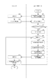
まず図1を参照して、本発明の第1の実施形態における、情報処理システムの構成の一例について説明する。
<First Embodiment>
First, an example of the configuration of the information processing system in the first embodiment of the present invention will be described with reference to FIG.
本発明の情報処理システムは、PC100、サーバ200がLAN101(ローカルエリアネットワーク)によって通信可能に接続されて構成されている。サーバ200には、CADソフト(CADソフトウェア)によって生成された3次元モデルのデータ(アセンブリファイルや部品ファイル等)が記憶されている。例えば、図8の801、802のようなデータが記憶されている。 The information processing system of the present invention is configured such that a PC 100 and a server 200 are communicably connected via a LAN 101 (local area network). The server 200 stores three-dimensional model data (an assembly file, a part file, etc.) generated by CAD software (CAD software). For example, data such as 801 and 802 in FIG. 8 is stored.
図8の800に示す、801及び802から成る3次元モデルは、例えば図8の810における、801と803を接触させた状態で、803の溝部分に樹脂を流し込み、固めることで生成される成果物の形状を示す。 The three-dimensional model composed of 801 and 802 shown in 800 of FIG. 8 is a result generated by pouring and hardening the resin into the groove portion of 803 in the state where 801 and 803 are in contact with each other in 810 of FIG. Indicates the shape of the object.
PC100にはCADソフトと、当該CADソフトから取得した情報をもとに、部品の重なりを判定する重なり判定ツールがインストールされているものとする。重なり判定ツールは、3次元モデルを上面から見た際に、上面(前面)にあるモデル(3次モデル(部品))の穴と、下面側(上面にとっての背面側)にあるモデルとが重なっているか判定し、重なっている位置を特定する。そして、重なっていると判定した位置を、当該穴を通して背面の部品を打ち抜くための打ち抜き箇所として決定する。つまり、背面の部品を打ち出すことを決定する。 It is assumed that the PC 100 is installed with CAD software and an overlap determination tool for determining the overlap of components based on information acquired from the CAD software. When the 3D model is viewed from the top, the overlap judgment tool overlaps the hole on the model (third-order model (part)) on the top surface (front surface) and the model on the bottom surface (back side for the top surface). And determine the overlapping position. Then, the position determined to be overlapped is determined as a punching location for punching the back part through the hole. In other words, it is determined to launch the rear part.
これにより、例えば、図11の1100における1101に示すような、801の板の穴を貫通して802の部品を打ち抜き、図11の1110に示すように、801から不要な部品である802を剥離させて、802と連結していた1106と801だけを必要な部品として残すための、新たな部品(打ち抜き用モデル/図11の1102、1103等)を容易に作成することができるようになる。
Thus, for example, a
つまりPC100は、例えば上から下方向に向けて、プレス機のように打ち抜き用モデル(打ち出し用部品)を移動させて当該不要な部品を剥離させる部品打ち出し装置で用いる、当該打ち出し用部品の設計をする装置である。以上が図1の説明である。 In other words, for example, the PC 100 designs the punching part to be used in a part punching device that moves the punching model (punching part) like a press machine and peels off the unnecessary part like a press machine. It is a device to do. The above is the description of FIG.
以下、図2を用いて、本発明の第1の実施形態における各種装置のハードウェア構成の一例について説明する。 Hereinafter, an example of the hardware configuration of various apparatuses according to the first embodiment of the present invention will be described with reference to FIG.
図2において、201はCPUで、システムバス204に接続される各デバイスやコントローラを統括的に制御する。また、ROM202あるいは外部メモリ211には、CPU201の制御プログラムであるBIOS(Basic Input / Output System)やオペレーティングシステムプログラム(以下、OS)や、各サーバ或いは各PCの実行する機能を実現するために必要な後述する各種プログラム等が記憶されている。
In FIG. 2,
203はRAMで、CPU201の主メモリ、ワークエリア等として機能する。CPU201は、処理の実行に際して必要なプログラム等をROM202あるいは外部メモリ211からRAM203にロードして、該ロードしたプログラムを実行することで各種動作を実現するものである。
A
また、205は入力コントローラで、キーボード(KB)209や不図示のマウス等のポインティングデバイス等からの入力を制御する。206はビデオコントローラで、CRTディスプレイ(CRT210)等の表示器への表示を制御する。なお、図2では、CRT210と記載しているが、表示器はCRTだけでなく、液晶ディスプレイ等の他の表示器であってもよい。これらは必要に応じて管理者が使用するものである。
An
207はメモリコントローラで、ブートプログラム,各種のアプリケーション,フォントデータ,ユーザファイル,編集ファイル,各種データ等を記憶するハードディスク(HD)や、フレキシブルディスク(FD)、或いはPCMCIAカードスロットにアダプタを介して接続されるコンパクトフラッシュ(登録商標)メモリ等の外部メモリ211へのアクセスを制御する。
A
208は通信I/Fコントローラで、ネットワーク(例えば、図1に示したLAN101)を介して外部機器と接続・通信するものであり、ネットワークでの通信制御処理を実行する。例えば、TCP/IPを用いた通信等が可能である。
A communication I /
なお、CPU201は、例えばRAM203内の表示情報用領域へアウトラインフォントの展開(ラスタライズ)処理を実行することにより、CRT210上での表示を可能としている。また、CPU201は、CRT210上の不図示のマウスカーソル等でのユーザ指示を可能とする。
Note that the
本発明を実現するための後述する各種プログラムは、外部メモリ211に記録されており、必要に応じてRAM203にロードされることによりCPU201によって実行されるものである。さらに、上記プログラムの実行時に用いられる定義ファイル及び各種情報テーブル等も、外部メモリ211に格納されており、これらについての詳細な説明も後述する。以上が図2の説明である。
Various programs to be described later for realizing the present invention are recorded in the
次に図3を参照して、本発明の第1の実施形態における機能構成の機能構成の一例について説明する。 Next, an example of a functional configuration of the functional configuration according to the first embodiment of the present invention will be described with reference to FIG.
3次元モデル記憶部331は、3次元モデルを記憶する記憶部である。例えば3次元モデルの名称(ファイル名)、参照関係、X,Y,Z=0,0,0を原点とした3次元空間上の3次元モデルの位置(X,Y,Z)や方向(X,Y,Z)、形状のデータを、3次元モデルのデータとして記憶している。X,Y,Zはそれぞれ、3次元空間における縦、横、高さ方向の軸であるものとする。
The three-dimensional
3次元モデル生成部311は、3次元モデル生成部指示受付部312において受け付けたユーザ操作又は重なり判定ツール等のツールからの指示により3次元モデルを生成する生成部である。3次元モデル記憶制御部313は、生成した3次元モデルを記憶部に記憶する制御部である。例えばサーバ200に3次元モデルのデータを送信して3次元モデル記憶部331に記憶するよう指示する。3次元モデル表示部314は、生成した3次元モデルを表示画面に表示する表示部である。
The 3D
オブジェクト記憶部321は、CADソフトから取得した3次元モデルの輪郭(輪郭を形成する線の集合)をオブジェクトとして記憶して管理する。輪郭線は、3次元モデルをある方向から投影した場合における3次元モデルの輪郭を示す線であり、輪郭を投影する二次元の面を投影面、輪郭線を投影した二次元の図を投影図というものとする。例えば、正面図、右側面図、左側面図、上面図等が投影図である。重なり判定部322は、複数のオブジェクトが重なっているか判定する判定部である。例えば、3次元モデルの上面図において、当該上面(前面)にあるモデルの穴であって、下面(上面にとっての背面)側のモデルと重なる位置にある穴があるか判定する。
The
つまり、前面から開いている穴の向こう側に打ち抜き可能な別の部品があるか判定する判定部である。 That is, it is a determination unit that determines whether there is another part that can be punched beyond the hole opened from the front surface.
打ち抜き対象特定部323は、重なり判定部で重なっていると判定された穴(穴の位置)を、例えば上方向から下方向に向けて別部品を挿入して背面にある部品を打ち抜く場所、として特定(決定)して記憶する。
The punching
識別表示部324は、重なり判定部322で重なっていると判定された場所を識別表示する表示部である。例えば、背面側の別モデルと重なる位置にある前面側の(手前の)モデルの穴を、打ち抜き対象の穴として特定して、色を変えて識別表示する。背面に別のモデルがない穴は打ち抜き対象として特定せず、識別表示もしない。
The
打ち抜き用モデル形状決定部325は、打ち抜き対象の箇所を打ち抜く3次元モデルの形状を決定する決定部である。打ち抜き用モデル生成指示部326は、打ち抜き用モデル形状決定部325で決定された3次元モデルを生成するようCADソフトに指示する指示部である。
The punching model
位置決定部327は、打ち抜き対象の箇所を打ち抜く3次元モデルを配置する位置であって、当該3次元モデルを設置する土台となる部材上の当該3次元モデルの位置を決定する決定部である。打ち抜き用モデル生成指示部326は、位置決定部327で決定された位置に当該3次元モデルを配置するようCADソフトに指示する。以上が図3の説明である。
The
次に図4を参照して、本発明の第1の実施形態における処理の概要について説明する。 Next, an overview of processing in the first embodiment of the present invention will be described with reference to FIG.
以下、図4〜図6の各ステップに示す処理は、PC100のCPU201が、PC100にインストールされたCADソフト又は重なり判定ツールの機能を用いて実行するものとする。
Hereinafter, the processing shown in each step of FIGS. 4 to 6 is executed by the
ユーザ操作により指定されたCADファイル(3次元モデル)を展開して当該CADファイルの情報を表示画面に表示する。例えば、アセンブリファイルの選択、展開操作を受け付け、図16の1600に示すような画面を表示する。1600ではアセンブリ1を展開している。参照関係の情報は各アセンブリファイルが保持している。参照関係の情報は、参照関係を保持するアセンブリファイルが、どのアセンブリ又は部品を参照しているかの情報、及び参照しているアセンブリ又は部品の3次元空間上におけるX,Y,Z座標を有する。つまり、部品同士の3次元空間(奥行き方向)における位置関係を記憶している。例えば高さ方向は、縦方向及び横方向に伸びる面にとっての奥行き方向である。
The CAD file (three-dimensional model) designated by the user operation is expanded and the information of the CAD file is displayed on the display screen. For example, an assembly file selection / development operation is accepted, and a screen such as 1600 in FIG. 16 is displayed. In 1600, the
1601はアセンブリファイルの参照している他のアセンブリファイルや部品のデータの参照関係を示すツリーを表示する表示部である。1603は、展開中のアセンブリの参照関係の情報に従って、部品形状を記憶した部品データを読みだして3次元空間上に配置して表示する表示部である。1602は、重なり判定ツールの起動ボタンである。
CADソフトは、ユーザ操作により重なり判定ツールの起動ボタンの押下の操作(起動指示)を受け付け、それに応じて重なり判定ツールを起動する(ステップS401)。CADソフトからの指示により起動した重なり判定ツールは(ステップS402)、メインダイアログ1610を表示し(ステップS403)、当該メインダイアログ1610に表示しているラジオボタン1612の選択を受け付けている状態で、「輪郭要求」ボタン1613の押下の操作を受け付ける。当該操作に応じて重なり判定ツールは、CADソフトのAPI(Application Programming Interface)を用いて、CADソフトで開いているファイル(3次元モデル)の輪郭の取得要求を行う(ステップS404)。
The CAD software accepts an operation (start-up instruction) for pressing the start button of the overlap determination tool by a user operation, and starts the overlap determination tool accordingly (step S401). The overlap determination tool activated by an instruction from the CAD software (step S402) displays the main dialog 1610 (step S403), and accepts the selection of the
当該「輪郭要求」ボタン1613の押下は、対象部品の指定及び指定された部品の穴を介して打ち出し可能な別の部品の存在を確認するための処理の実行指示である。
The pressing of the “contour request”
具体的には、CADソフトに対して、CADソフトで展開中のモデルの面の一覧を要求して取得し、当該面の一覧から任意の条件(具体的にはZ軸方向の上面等)に合致する面を取得する。そして、当該面の輪郭線のうち、所定のモデル(予め重なり判定ツールに登録されているファイル名の部品)の輪郭線と、当該所定のモデルの背面側にある別のモデルの輪郭(外形線)を要求する。例えば所定のモデルXの前面側(例:高さ方向における上面側)に位置するモデルのファイル名にはfrontという文字列が含まれ、背面側に位置するモデルのファイル名にはbackという文字列が含まれるよう、モデルを生成して記憶しておく。そして、重なり判定ツールは、モデル名称=Xの部品の輪郭線と、ファイル名にbackの文字列が含まれるモデルの輪郭線をCADソフトに要求するものとする。 Specifically, the CAD software is requested and obtained from a list of model surfaces being developed by the CAD software, and an arbitrary condition (specifically, an upper surface in the Z-axis direction, etc.) is obtained from the list of surfaces. Get matching faces. Among the contour lines of the surface, the contour line of a predetermined model (file name component registered in the overlap determination tool in advance) and the contour of another model on the back side of the predetermined model (outline) ). For example, the character string “front” is included in the file name of the model located on the front side (eg, the upper surface side in the height direction) of the predetermined model X, and the character string “back” is included in the file name of the model located on the back side. A model is generated and stored so that is included. Then, it is assumed that the overlap determination tool requests the CAD software for the contour line of the part with model name = X and the contour line of the model whose file name includes the character string “back”.
更に具体的には、ここでいう展開中のモデルとは、複数の部品の3次元モデルを参照しているアセンブリファイルであり、重なり判定ツールは「輪郭要求」ボタン1613の押下を受け付けることで当該アセンブリが参照している複数の部品の面(例えば上面)を特定するようCADソフトに指示する。
More specifically, the model being developed here is an assembly file that refers to a three-dimensional model of a plurality of parts, and the overlap determination tool receives the press of the “contour request”
つまり、3次元空間における上から下に直行するZ軸の方向を特定して、当該Z軸方向における部品の前面(上面)の特定指示をしている。 In other words, the direction of the Z-axis that goes straight from top to bottom in the three-dimensional space is specified, and the front (upper surface) of the component in the Z-axis direction is specified.
また、それらの面の中で所定の部品(例:モデルX)の上面と、その部品の背面側にある部品の上面の輪郭線をCADソフトに要求する。つまり、上面に直交する方向である高さ方向を特定し(方向特定手段に該当)、当該方向において当該部品の裏側(背面側)にある部品の輪郭線を要求する。なお、当該所定のモデルのファイル名は予めPC100の外部メモリに記憶されているものとする。
Also, the CAD software is requested for the upper surface of a predetermined component (eg, model X) and the contour line of the upper surface of the component on the back side of the component among these surfaces. That is, the height direction which is a direction orthogonal to the upper surface is specified (corresponding to the direction specifying means), and the contour line of the component on the back side (back side) of the component in the direction is requested. It is assumed that the file name of the predetermined model is stored in advance in the external memory of the
「輪郭要求」ボタン1613の押下は、CADソフトで展開中のアセンブリファイルを指定し、当該指定によりアセンブリファイルが参照している部品の中の所定の部品を指定し、指定した部品の穴を介して打ち出し可能な別の部品の存在を確認するための処理の実行操作である。
When the “contour request”
CADソフトは当該指示及び要求を受け付けて(ステップS405)、要求に応じて、上から(Z軸方向のプラスからマイナスに向かう方向から)3次元モデルを見た場合における、展開中のファイルの中のモデルXの輪郭線及びモデルXの背面側にある部品の輪郭線を生成し、重なり判定ツールに返信する(ステップS406)。例えば3次元モデルの上面図のような輪郭線のX,Y座標(Z軸方向と交差する平面における各輪郭線の頂点位置)の集合を生成して返信する。上面図の輪郭の一例を図9に示す。図9の900に、図8の800に示す3次元モデルの輪郭線を示す。 The CAD software receives the instruction and request (step S405), and in response to the request, in the file being developed when the 3D model is viewed from above (from the direction of plus to minus in the Z-axis direction). The outline of the model X and the outline of the part on the back side of the model X are generated and returned to the overlap determination tool (step S406). For example, a set of contour X and Y coordinates (vertex position of each contour line in a plane intersecting the Z-axis direction) as shown in the top view of the three-dimensional model is generated and returned. An example of the contour of the top view is shown in FIG. 900 of FIG. 9 shows the outline of the three-dimensional model shown by 800 of FIG.
生成して重なり判定ツールに返信する輪郭線の座標の情報の中の、部品Xの背面側の部品の輪郭線の情報の一例を図7の背面オブジェクト情報720に示す。この時点ではオブジェクト名は空である。 An example of the contour information of the component on the back side of the component X in the coordinate information of the contour line generated and returned to the overlap determination tool is shown in the back object information 720 of FIG. At this point, the object name is empty.
重なり判定ツールは当該所定のモデル(部品X)とその背面側にある各部品の輪郭線の情報をCADソフトから受信して取得し、所定のモデルの輪郭線のうち当該所定のモデル上に存在する穴の輪郭線(穴オブジェクト)を抽出してオブジェクト情報710に挿入し、外部メモリに記憶する(ステップS407)。つまり、所定のモデルの上面から開いている穴の位置の情報を特定して記憶する。また、当該所定のモデルの背面側にあるモデルの外形線を抽出して、当該外形線を示す輪郭線の情報を図7の720に挿入し、外部メモリに記憶する。 The overlap determination tool receives and acquires information about the predetermined model (part X) and the outline of each part on the back side from CAD software, and exists on the predetermined model among the outlines of the predetermined model The outline (hole object) of the hole to be extracted is extracted, inserted into the object information 710, and stored in the external memory (step S407). That is, information on the position of a hole opened from the upper surface of a predetermined model is specified and stored. Further, the outline of the model on the back side of the predetermined model is extracted, and information on the outline indicating the outline is inserted into 720 in FIG. 7 and stored in the external memory.
図7のオブジェクト情報710は、3次元モデル711(部品)において、線(線名称713)が繋がって形成されるオブジェクト(オブジェクト名712)の輪郭を示す情報である。線種別714は各線(線名称713)の線分の属性を示す。
The object information 710 in FIG. 7 is information indicating the outline of an object (object name 712) formed by connecting lines (line names 713) in the three-dimensional model 711 (parts). The
重なり判定ツールは、取得したオブジェクトにオブジェクト名を付与し、オブジェクトを構成する線(線分、具体的にはモデル上のエッジ)に対して直線・円弧・真円の線種別を付与して整理(CADソフトから取得した輪郭線の各線分の属性に含まれる線の種別をオブジェクト情報710に書き込み)、スプライン等のその他線分は始終点を結ぶ直線に置換してオブジェクト情報710へ格納する。lineは直線を示し、arcは円弧を示し、circleは真円を示す。それぞれの線は、始点,終点715、半径716、中央座標717、開始角度・回転角度718を、それぞれ必要な値だけ保持しているものとする。どの線種別の線がどの項目に値を保持しているかは例えば710に示す通りである。オブジェクト情報710には、ステップS404で重なり判定ツールがファイル名を指定した所定のモデルの輪郭線の情報であって、当該モデル上の穴の輪郭線を記憶しているものとする。例えば図8の801上の穴の輪郭線の情報を示す。
The overlap determination tool assigns an object name to the acquired object, and arranges the line type (line segment, specifically, the edge on the model) by assigning a line type of straight line, arc, or perfect circle to the object. (The line type included in the attribute of each contour line acquired from the CAD software is written in the object information 710), and other line segments such as splines are replaced with straight lines connecting the start and end points and stored in the object information 710. Line indicates a straight line, arc indicates an arc, and circle indicates a perfect circle. Each line holds a start point, an
背面オブジェクト情報720は、オブジェクト情報710の示すオブジェクトの背面側にある3次元モデルの外形の輪郭線の情報を示す。例えば図8の802の部品の外形線の情報である。各項目の値は710の説明で上述したとおりのため説明は割愛する。
The back object information 720 indicates the outline information of the outline of the 3D model on the back side of the object indicated by the object information 710. For example, the outline information of the
重なり判定ツールはステップS407で記憶したオブジェクトの情報(輪郭線の情報/図7の710、720)をメモリに読み出す(ステップS408/取得する)。そして処理をステップS409に移行し、重なり判定処理を実行する(ステップS409)。第1の実施形態におけるステップS409の処理の詳細は図5の説明で後述する。 The overlap determination tool reads the object information (contour line information / 710 and 720 in FIG. 7) stored in step S407 into the memory (step S408 / obtains). Then, the process proceeds to step S409, and an overlap determination process is executed (step S409). Details of the processing in step S409 in the first embodiment will be described later with reference to FIG.
ここで図5を参照して、本発明の第1の実施形態における、重なり判定処理の流れについて説明する。 Here, with reference to FIG. 5, the flow of the overlap determination process in the first embodiment of the present invention will be described.
重なり判定ツールは、オブジェクト情報710の中の未処理の穴オブジェクト(オブジェクト名でグルーピングされた線の集合)を1つ取得し(ステップS501)、背面オブジェクト情報720のオブジェクトを1つ取得する(ステップS502)。そして、ステップS502で取得したオブジェクト(背面オブジェクト)の線分のうち、未処理の線分を1つ取得し(ステップS503)、図7の730に示すカウンタを初期化して(ステップS504)、ステップS502(または後述するステップS516)で取得した背面オブジェクトのオブジェクト名をオブジェクト名731に、ステップS503(または後述するステップS517)で取得した線分の名称を線名称732に、ステップS501(または後述するステップS518)で取得したオブジェクト名をカウント対象オブジェクト名733に挿入して記憶する。当該カウンタ730の役割については後述する。
The overlap determination tool acquires one unprocessed hole object (a set of lines grouped by object name) in the object information 710 (step S501), and acquires one object of the back object information 720 (step S501). S502). Then, one unprocessed line segment is acquired from the line segments of the object (back object) acquired in step S502 (step S503), the counter indicated by 730 in FIG. 7 is initialized (step S504), and step The object name of the back object acquired in S502 (or step S516 described later) is the
重なり判定ツールは、図10の1000に示すような、水平方向へ仰角1度以上の任意角度に傾いた仮想の直線(仮想直線1001)を生成し、図10に示すように、ステップS503で取得した線分の始点に配置する(ステップS505)。 The overlap determination tool generates a virtual straight line (virtual straight line 1001) tilted at an arbitrary angle of 1 degree or more in the horizontal direction as indicated by 1000 in FIG. 10, and is acquired in step S503 as shown in FIG. It arrange | positions to the starting point of the performed line segment (step S505).
例えば任意角度(所定の仰角)は3度であるものとする。所定の仰角の値はPC100の外部メモリに記憶されており、不図示の設定画面を介したユーザ操作で任意に設定変更可能であるものとする。そして、ステップS501で取得したオブジェクトの線分のうち、未処理の線分を1つ取得する(ステップS506)。
For example, it is assumed that the arbitrary angle (predetermined elevation angle) is 3 degrees. It is assumed that the predetermined elevation angle value is stored in the external memory of the
重なり判定ツールは、ステップS505で配置した仮想直線1001と、取得した穴のオブジェクトを構成する線分に交点があるか判定し(ステップS507)、交点がある場合はカウンタ730の交点数734を1カウントアップして(ステップS508)処理をステップS509に移行する。交点がない場合は、処理をステップS509に移行する。 The overlap determination tool determines whether there is an intersection between the virtual straight line 1001 arranged in step S505 and the line segment constituting the acquired hole object (step S507). If there is an intersection, the number of intersections 734 of the counter 730 is set to 1. Count up (step S508), and the process proceeds to step S509. If there is no intersection, the process proceeds to step S509.
重なり判定ツールは、ステップS507で交点の有無を判定した穴の線分(710の線分)が、ステップS501で取得した穴のオブジェクトを構成する未処理の線分のうち最後の線分か判定する(ステップS509/つまりステップS501で取得した穴の線分全てを処理したか判定する)。未処理の線分がまだ残っている場合には、ステップS501で取得した穴のオブジェクトの線分のうち未処理の線分を1つ取得して(ステップS515)処理をステップS507に移行する。 The overlap determination tool determines whether the hole line segment (710 line segment) that has been determined whether there is an intersection in step S507 is the last of the unprocessed line segments that constitute the hole object acquired in step S501. (Step S509 / that is, it is determined whether all the hole line segments acquired in Step S501 have been processed). If an unprocessed line segment still remains, one unprocessed line segment is acquired from the hole object line segments acquired in step S501 (step S515), and the process proceeds to step S507.
ステップS501で取得した穴オブジェクトの全ての線分を処理した場合、重なり判定ツールは、カウンタ730の交点数734の値が奇数か偶数か判定する(ステップS510)。交点数が奇数の場合には、図10に示すように、ステップS503(または後述するステップS516)で取得した処理中の背面オブジェクトの線分は、ステップS501(または後述するステップS518)で取得した、仮想直線が交差した穴オブジェクトと重なっていると判定(決定)し、処理をステップS514に移行する。また、当該ステップS501で取得した穴オブジェクト(または後述するステップS518で取得した穴オブジェクト)を、背面のオブジェクトと重なる位置にある穴であって、背面のモデルを打ち抜く場所として特定し、外部メモリに記憶する(ステップS514)。具体的には、図7の740に示すように、どのモデル(部品名741)の、どのオブジェクト(対象部742)が打ち抜き対象の場所を示すかを記憶する。 When all the line segments of the hole object acquired in step S501 have been processed, the overlap determination tool determines whether the value of the intersection number 734 of the counter 730 is odd or even (step S510). When the number of intersection points is an odd number, as shown in FIG. 10, the line segment of the back object being processed acquired in step S503 (or step S516 described later) is acquired in step S501 (or step S518 described later). Then, it is determined (determined) that the virtual straight line overlaps the intersecting hole object, and the process proceeds to step S514. Further, the hole object acquired in step S501 (or the hole object acquired in step S518 described later) is a hole at a position overlapping with the object on the back surface, and is specified as a place where the back model is punched, and stored in the external memory. Store (step S514). Specifically, as indicated by reference numeral 740 in FIG. 7, which model (part name 741) and which object (target part 742) indicates the location to be punched are stored.
つまり、カウンタ730の交点数734の値が奇数であった穴について、当該穴を介して打ち抜き可能な背面側の部品が存在すると判定し、当該穴を介して背面側の部品を打ち出すことを決定する。 In other words, it is determined that there is a back side part that can be punched through the hole for the hole having an odd number of intersections 734 of the counter 730, and the back side part is determined to be driven through the hole. To do.
交点数が偶数又は0の場合には、図10に示すように、ステップS503等(または後述するステップS516)で取得した処理中の背面オブジェクトの線分は、穴オブジェクトと重なっていないと判定(決定)し、処理をステップS511に移行する。 When the number of intersection points is even or 0, as shown in FIG. 10, it is determined that the line segment of the back object being processed acquired in step S503 or the like (or step S516 described later) does not overlap with the hole object ( Determination), and the process proceeds to step S511.
重なり判定ツールは、処理中の背面オブジェクトの線分は、当該背面オブジェクトを形成する未処理の線分のうち最後の線分か判定する(ステップS511/つまり、ステップS502または後述するS517で取得したオブジェクトであって、所定の部品Xの背面側にあるオブジェクトの全ての線分を処理したか判定する)。未処理の線分がある場合には、処理中の背面オブジェクトの線分のうち未処理の線分を1つ取得して(ステップS516)、処理をステップS504に移行する。 The overlap determination tool determines whether the line segment of the back object being processed is the last line segment of the unprocessed line segments that form the back object (step S5111 / that is, acquired in step S502 or S517 described later) It is determined whether or not all the line segments of the object on the back side of the predetermined part X have been processed). If there is an unprocessed line segment, one unprocessed line segment is acquired from the line segments of the background object being processed (step S516), and the process proceeds to step S504.
処理中の背面オブジェクトを構成する線分の全てを処理した場合には、重なり判定ツールは、背面オブジェクト情報720内の全ての背面オブジェクトを処理したか判定する(ステップS512)。未処理の背面オブジェクトがある場合は、未処理の背面オブジェクトを1つ取得して(ステップS517)、処理をステップS503に移行する。全ての背面オブジェクトを処理済みの場合は処理をステップS513に移行する。 If all the line segments constituting the back object being processed have been processed, the overlap determination tool determines whether all the back objects in the back object information 720 have been processed (step S512). If there is an unprocessed back object, one unprocessed back object is acquired (step S517), and the process proceeds to step S503. If all the back objects have been processed, the process proceeds to step S513.
重なり判定ツールは、オブジェクト情報710内の全ての穴オブジェクトを処理したか判定する(ステップS513)。 The overlap determination tool determines whether all hole objects in the object information 710 have been processed (step S513).
つまり、ユーザ操作で指定された所定の部品Xの前面に開いている穴(例:高さ方向において上面に開いている穴)の中に、処理中の背面オブジェクトと重なっているかの判定を行っていない穴があるか判定する。未処理の穴オブジェクトがある場合は、未処理の穴オブジェクトを取得して(ステップS518)、処理をステップS502に移行する。全ての穴オブジェクトを処理している場合は、図5の処理を終了する。以上が図5の説明である。 That is, it is determined whether or not a hole that is open on the front surface of a predetermined part X specified by a user operation (eg, a hole that is open on the upper surface in the height direction) overlaps the rear object being processed. Judge whether there is a hole that is not. If there is an unprocessed hole object, an unprocessed hole object is acquired (step S518), and the process proceeds to step S502. If all the hole objects have been processed, the processing in FIG. 5 ends. The above is the description of FIG.
図4の説明に戻る。重なり判定ツールは、ステップS410で、ステップS409の判定結果(図7の打ち抜き対象部740)をメモリから読み出して取得し、対象部742の示すオブジェクトを表示画面上に識別表示する(ステップS410)。
Returning to the description of FIG. In step S410, the overlap determination tool reads out and acquires the determination result in step S409 (the punching target portion 740 in FIG. 7) from the memory, and identifies and displays the object indicated by the
例えば、打ち抜き対象部740に記憶された穴オブジェクトを選択状態とし、選択状態の穴オブジェクトの色を選択状態であることを示す色(例:赤色)に変更して識別表示する。識別表示の様子の一例を、図10の1010における、1011等に示す。その後処理をステップS411に移行する。ステップS411の処理の詳細は図6の説明で後述する。 For example, the hole object stored in the punching target part 740 is selected, and the color of the hole object in the selected state is changed to a color (for example, red) indicating that it is in the selected state, and is displayed. An example of the state of identification display is shown at 1011 in 1010 of FIG. Thereafter, the process proceeds to step S411. Details of the processing in step S411 will be described later with reference to FIG.
以上説明したように、本発明によれば、部品の穴と別の部品が重なる位置を容易に特定可能な仕組みを提供することができる。 As described above, according to the present invention, it is possible to provide a mechanism that can easily identify a position where a hole of a part and another part overlap.
例えば、所定のモデルの穴の向こう側に別のモデルが存在する場合に、当該別のモデルを打ち抜く対象として、当該穴を特定して記憶することができる。 For example, when another model exists beyond the hole of a predetermined model, the hole can be specified and stored as an object to be punched.
つまり、部品の背面側にある当該部品の穴を介して打ち抜き可能な別の部品の有無に伴う決定を容易に行うことができる仕組みを提供することができる。 That is, it is possible to provide a mechanism that can easily determine whether there is another part that can be punched through the hole of the part on the back side of the part.
また、当該特定した打ち抜き対象の穴を表示画面上に識別表示することで、打ち抜き対象箇所をユーザに確認させることができる。 In addition, by identifying and displaying the identified hole to be punched on the display screen, the user can confirm the location to be punched.
次に図6を参照して、本発明の第1の実施形態における、新規オブジェクトの生成・配置処理の流れについて説明する。 Next, a flow of new object generation / arrangement processing in the first embodiment of the present invention will be described with reference to FIG.
重なり判定ツールは、打ち抜き対象部740の穴の軸方向と同じ軸上(同じ方向上)に、当該穴と同じ方向(例えば上から下)を向いて配置されている3次元モデルの一覧をCADソフトに要求する(ステップS601)。なお、要求するモデル一覧は、例えば穴の空いた3次元モデル(例:図8の801)よりも、Z軸上の上から下に向けた方向において、当該穴よりも手前に配置されている(名称にfrontの文字列が含まれている)モデルのうち、穴と同じ軸上に穴と同じ方向を向いて配置されているモデルの一覧である。 The overlap determination tool CAD displays a list of three-dimensional models arranged on the same axis (in the same direction) as the hole of the punching target part 740 and facing the same direction (for example, from the top to the bottom) of the hole. A request is made to the software (step S601). The requested model list is arranged in front of the hole in the direction from the top to the bottom on the Z axis, for example, with respect to the three-dimensional model with a hole (for example, 801 in FIG. 8). It is a list of models that are arranged on the same axis as the hole and facing the same direction as the hole among the models (the name includes the front character string).
更に具体的には、重なり判定ツールは、打ち抜き対象部740をCADソフトに送信すると共に、当該打ち抜き対象部740に含まれる各穴の中心軸の仮想線を生成して当該仮想線と干渉する部品の中の当該軸の穴よりも手前側にある部品一覧を要求する。 More specifically, the overlap determination tool transmits a punching target portion 740 to CAD software, and generates a virtual line of the central axis of each hole included in the punching target portion 740 and interferes with the virtual line. A list of parts on the near side of the hole in the shaft is requested.
CADソフトは当該要求を受け付けると(ステップS602)、要求に応じたモデルの一覧を重なり判定ツールに返信する(ステップS603)。 When the CAD software accepts the request (step S602), it returns a model list corresponding to the request to the overlap determination tool (step S603).
具体的には、CADソフトは、重なり判定ツールからの要求に応じて、重なり判定ツールから受信した打ち抜き対象部740に含まれる各穴の中心軸の仮想線を生成し、当該仮想線と干渉する部品の中で、干渉した軸の穴よりも手前側にある部品のファイル名一覧を穴ごと(ループしている線の各線分の線名称及び各線分の始点・終点の位置のグループ)ごとに生成して、重なり判定ツールに返信する。 Specifically, in response to a request from the overlap determination tool, the CAD software generates a virtual line of the center axis of each hole included in the punching target portion 740 received from the overlap determination tool and interferes with the virtual line. In the part, list the file name of the part on the near side of the hole of the axis that interfered with each hole (the group of the line name of each looped line segment and the start point / end point position of each line segment). Generate and send it back to the overlap determination tool.
重なり判定ツールはこれを受信し(ステップS604)、全ての穴オブジェクトについて、穴に対応する形状の3次元モデルが、穴と同じ軸上に配置されているか判定する(ステップS605)。つまり、CADソフトから受信した各穴の手前にある部品のファイル名一覧に、当該穴に対応する形状の部品が存在するか判定する。 The overlap determination tool receives this (step S604), and for all hole objects, determines whether the three-dimensional model having the shape corresponding to the hole is arranged on the same axis as the hole (step S605). That is, it is determined whether or not there is a component having a shape corresponding to the hole in the file name list of the component in front of each hole received from the CAD software.
穴に対応する形状の3次元モデルとは、PC100の外部メモリに予め記憶されている不図示の対応付けファイルに記憶されている、穴オブジェクトを構成する線種別の組み合わせに対応するファイル名の3次元モデルである。例えば、線種別=circleには、円柱形のモデル1つから構成される3次元モデルのファイル名(例:x01.prt)が対応付けられている。また、線種別=line及びarcの組み合わせには、円柱形のモデル2つから構成される3次元モデルのファイル名(アセンブリファイル名/例:x02.asm)が対応付けられているものとする。
A three-dimensional model of a shape corresponding to a hole is a file name 3 corresponding to a combination of line types constituting a hole object, which is stored in an unillustrated association file stored in advance in the external memory of the
重なり判定ツールは、全ての穴オブジェクトについて、穴に対応する形状の3次元モデルが、穴と同じ軸上に配置されていると判定した場合、処理を終了する。対応する3次元モデルが配置されていない穴があると判定された場合は、図14に示すようなダイアログを表示画面に表示する(ステップS606)。 The overlap determination tool ends the process when it is determined that the three-dimensional model having the shape corresponding to the hole is arranged on the same axis as the hole for all the hole objects. If it is determined that there is a hole in which the corresponding three-dimensional model is not arranged, a dialog as shown in FIG. 14 is displayed on the display screen (step S606).
重なり判定ツールは、ダイアログ1400(図14)において、穴に対応する形状の3次元モデルの生成・配置の操作を受け付けたか(「はい」ボタンの押下を受け付けたか)判定する(ステップS607)。穴に対応する形状の3次元モデルの生成・配置の操作を受け付けなかった場合(「いいえ」ボタンの押下を受け付けた場合)は処理を終了する。穴に対応する形状の3次元モデルの生成・配置の操作を受け付けた場合は、処理をステップS608に移行する。 The overlap determination tool determines whether an operation for generating and arranging a three-dimensional model having a shape corresponding to a hole has been received (whether the “Yes” button has been pressed) has been received in the dialog 1400 (FIG. 14) (step S607). If the operation for generating / arranging the three-dimensional model having the shape corresponding to the hole is not received (when the “No” button is pressed), the process ends. If an operation for generating and arranging a three-dimensional model having a shape corresponding to the hole is received, the process proceeds to step S608.
重なり判定ツールは、ステップS608で、打ち抜き対象部740における対象部742(穴オブジェクト)の形状を取得する(ステップS608)。 In step S608, the overlap determination tool acquires the shape of the target part 742 (hole object) in the punching target part 740 (step S608).
具体的には、重なり判定ツールは、対応する形状の3次元モデルが3次元空間上に配置されていない穴オブジェクトのオブジェクト名を、オブジェクト情報710に記憶されたオブジェクト名と線名称及び線の始点・終点の位置と、CADソフトから受信した一覧と、外部メモリに記憶されている穴に対応する形状の3次元モデルの情報とを用いて特定する。 Specifically, the overlap determination tool calculates the object name of the hole object in which the corresponding three-dimensional model of the shape is not arranged in the three-dimensional space, the object name stored in the object information 710, the line name, and the starting point of the line. -Specify using the position of the end point, the list received from the CAD software, and the information of the three-dimensional model of the shape corresponding to the hole stored in the external memory.
つまり、打ち抜き対象部740の中で、対応する形状の3次元モデルが3次元空間上に配置されていない穴オブジェクトを特定する。 That is, the hole object in which the corresponding three-dimensional model is not arranged in the three-dimensional space is specified in the punching target portion 740.
以降、対応する形状の3次元モデルが3次元空間上に配置されていない穴オブジェクトの数だけ、ステップS609〜S611の処理を繰り返し実行する。 Thereafter, the processes in steps S609 to S611 are repeatedly executed for the number of hole objects for which the corresponding three-dimensional model is not arranged in the three-dimensional space.
重なり判定ツールは、ステップS608で取得した、対応する形状の3次元モデルが3次元空間上に配置されていない穴オブジェクトのうち、未処理の穴オブジェクトを1つ取得する。 The overlap determination tool acquires one unprocessed hole object among the hole objects in which the corresponding three-dimensional model acquired in step S608 is not arranged in the three-dimensional space.
そして、例えば、取得した当該対象部742の示す、穴オブジェクトがどの種類の線分の組み合わせから成るかを、当該オブジェクトを構成する線種別を取得することで特定する。そして、当該穴オブジェクトの形状に対応するファイル名のモデルを外部メモリから読み出して取得する(ステップS609)。つまり、穴を介して部品を打ち抜く打ち抜き用部品の形状を決定する。当該3次元モデルのファイルはサーバ200の所定の記憶領域に予め記憶されているものとする。
Then, for example, what type of line segment combination the hole object indicated by the acquired
重なり判定ツールは、取得した穴の直径から、所定の長さだけクリアランスを設けた輪郭を穴の内側に生成し、ステップS609で取得したモデルの直径を当該生成した輪郭の直径とすることを決定する。つまり、新規に生成する部品の形状、サイズを決定する(サイズ決定手段に該当)。 The overlap determination tool determines from the acquired hole diameter that a contour with a predetermined length of clearance is generated inside the hole, and the diameter of the model acquired in step S609 is determined as the generated contour diameter. To do. That is, the shape and size of a newly generated component are determined (corresponding to size determining means).
重なり判定ツールは、ステップS609で取得した3次元モデルのファイル名をCADソフトに通知し、当該ファイル名のモデルを、所定の位置に配置するようCADソフトに指示する(ステップS611/生成制御手段、配置制御手段に該当)。ここでいう所定の位置とは、例えば処理中の3次元モデル(例:図8、図11の801)に対応付けて記憶されている位置であって、(例えばステップS608で取得した穴オブジェクトがcircleの場合)当該穴オブジェクトの示す3次元モデル上の穴の軸上の点であり、当該穴の中心点から所定距離分Z軸方向に距離をとった位置である。例えば図11の穴1104にとっての所定の位置は1102である。穴の中心点とは、例えば部品801の上面と同じ平面ベクトル上における穴の中心の位置である。また、ステップS608で取得した穴オブジェクトがarc(円弧)を含む場合、arcの中央点から所定距離分Z軸方向に距離をとった位置を、前記所定の位置とする(位置決定手段に該当)。穴1105に対応する所定の位置は、複数の位置1103(複数の点)である。重なり判定ツールは当該所定の位置を特定してCADソフトに通知して、当該所定の位置に、ステップS609で取得した3次元モデルを、ステップS610で決定した直径に変更して配置するよう指示する。
The overlap determination tool notifies the CAD software of the file name of the three-dimensional model acquired in step S609, and instructs the CAD software to place the model of the file name at a predetermined position (step S611 / generation control means, Applicable to placement control means). The predetermined position here is, for example, a position stored in association with the three-dimensional model being processed (for example, 801 in FIGS. 8 and 11) (for example, the hole object acquired in step S608). In the case of circle), this is a point on the axis of the hole on the three-dimensional model indicated by the hole object, and is a position that is a predetermined distance away from the center point of the hole in the Z-axis direction. For example, the predetermined position for the
CADソフトは当該指示を受け付け(ステップS612)、受け付けた指示に従って、穴に対応する3次元モデルを取得してコピーし(生成し)、サイズ変更し、所定の位置に配置する処理を行う(ステップS613)。例えば、図11に示す1101〜1103のようなピン状の打ち抜き用の3次元モデルを生成し、3次元モデル(部品801)を参照しているアセンブリに参照させるようアセンブリを編集して記憶することで、1100に示す801と1101〜1103を1つの表示画面上に表示する。図11の1110は、不要な部品802(除去部)を打ち抜いて除去した際のイメージを示す。 The CAD software accepts the instruction (step S612), and acquires, copies (generates) a three-dimensional model corresponding to the hole in accordance with the accepted instruction, changes the size, and performs a process of placing it at a predetermined position (step S612). S613). For example, a pin-shaped three-dimensional model for punching such as 1101 to 1103 shown in FIG. 11 is generated, and the assembly is edited and stored so that the assembly referring to the three-dimensional model (part 801) is referred to. Thus, 801 and 1101 to 1103 indicated by 1100 are displayed on one display screen. 1110 of FIG. 11 shows an image when an unnecessary part 802 (removal part) is punched and removed.
図11の所定の位置1102及び所定の位置1103は、打ち抜き用の3次元モデルの一部とするピン状の部品の位置(1102及び1103の位置)を、当該ピン状の部品が、打ち抜き用の3次元モデルにおける土台である1101に接する位置である。つまり、穴の中心点からピン状の部品が土台となる部材(部品)に接する距離分(所定距離分)Z軸方向に距離をとった位置である。
The
当該ピン状の部品が接している土台の部材上の位置が、当該ピン状の部品を配置する当該部材上の位置である。すなわち、重なり判定ツールは、穴を介して背面オブジェクトを打ち出すピン状の部品の当該部材上の位置を決定している。 The position on the base member where the pin-shaped component is in contact is the position on the member where the pin-shaped component is placed. That is, the overlap determination tool determines the position on the member of the pin-shaped part that strikes the back object through the hole.
なお、801の部品と1101の部品の距離が一定の場合には、ピン状の部品を配置する高さ方向(Z軸方向)の位置は予め決定しておき、当該ピン状の部品を配置する縦軸・横軸方向(X軸、Y軸方向)の位置を、背面の部品を打ち出すべき穴の位置に決定するようにしてもよい。 If the distance between the 801 component and the 1101 component is constant, the position in the height direction (Z-axis direction) where the pin-shaped component is arranged is determined in advance, and the pin-shaped component is arranged. You may make it determine the position of a vertical axis | shaft and a horizontal axis direction (X-axis, Y-axis direction) to the position of the hole which should punch out components of a back surface.
重なり判定ツールは、ステップS608で特定して取得した、対応する形状の3次元モデルが3次元空間上に配置されていない穴オブジェクトの中の全ての穴オブジェクトについて、ステップS609〜S611の処理を実行済か判定する。 The overlap determination tool executes the processing of steps S609 to S611 for all hole objects in the hole objects that are identified and acquired in step S608 and for which the corresponding three-dimensional model is not arranged in the three-dimensional space. Judge whether it is finished.
未処理の穴オブジェクトがある場合は、未処理の穴オブジェクトを1つ取得し、処理をステップS609に戻して、S609〜S611の処理を実行する。すべての穴オブジェクトを処理済の場合は図6の処理を終了する。以上が図6の説明である。 If there is an unprocessed hole object, one unprocessed hole object is acquired, the process returns to step S609, and the processes of S609 to S611 are executed. If all the hole objects have been processed, the processing in FIG. 6 is terminated. The above is the description of FIG.
図6の処理によれば、別の部品と重なる穴に対応する新しい部品を容易に生成し、配置することができる。 According to the process of FIG. 6, a new part corresponding to a hole overlapping with another part can be easily generated and arranged.
また、背面側にある部品を穴を介して打ち出すための新しい部品を配置する部材上の位置を決定することができる。 Moreover, the position on the member which arrange | positions the new component for driving out the component in the back side through a hole can be determined.
なお、図5のステップS512とステップS513の判定のタイミングを入れ替えて本発明を実現してもよい。 Note that the present invention may be realized by switching the determination timings of step S512 and step S513 in FIG.
具体的には、重なり判定ツールが、図5のステップS511において、処理中の背面オブジェクトの線分が当該背面オブジェクトを形成する未処理の線分のうち最後の線分であると判定された場合(ステップS511でYESの場合)は処理をステップS513に移行する。 Specifically, when the overlap determination tool determines in step S511 in FIG. 5 that the line segment of the back object being processed is the last line segment among the unprocessed line segments that form the back object. If (YES in step S511), the process proceeds to step S513.
ステップS513においては、オブジェクト情報710内の全ての穴オブジェクトについて処理中の背面オブジェクトとの重なりを判定したか判定する。そして、オブジェクト情報710内の全ての穴オブジェクトについて処理中の背面オブジェクトとの重なりを判定済であると判定された場合は処理をステップS518に移行し、判定済でないと判定された場合(つまり、当該波面オブジェクトの線分から引いた仮想直線との交点の有無を判定し終わっていない穴オブジェクトが残っている場合)は、処理をステップS512に移行する。 In step S513, it is determined whether all hole objects in the object information 710 have been determined to overlap with the back object being processed. When it is determined that the overlap with the back object being processed has been determined for all the hole objects in the object information 710, the process proceeds to step S518, and when it is determined that the determination has not been made (that is, If a hole object that has not been determined whether or not there is an intersection with a virtual straight line drawn from the line segment of the wavefront object remains), the process proceeds to step S512.
ステップS512では、重なり判定ツールは、背面オブジェクト情報720内の全ての背面オブジェクトを処理したか判定する(ステップS512)。つまり、全ての背面オブジェクトについて、穴オブジェクトとの交点数をカウント済か判定する。未処理の背面オブジェクトがある場合は処理をステップS517に移行して未処理の背面オブジェクトを1つ取得し、ステップS503に処理を移行する。全ての背面オブジェクトを処理済みの場合は図5の処理を終了する。 In step S512, the overlap determination tool determines whether all the back objects in the back object information 720 have been processed (step S512). That is, it is determined whether the number of intersections with the hole object has been counted for all the back objects. If there is an unprocessed back object, the process proceeds to step S517 to acquire one unprocessed back object, and the process proceeds to step S503. If all the back objects have been processed, the processing in FIG. 5 is terminated.
<第2の実施形態>
次に図17、図18を参照して、本発明の第2の実施形態について説明する。第2の実施形態では、穴を基準として、当該穴の開いている部品の背面側にある部品と当該穴が重なっているかを判定する。
<Second Embodiment>
Next, a second embodiment of the present invention will be described with reference to FIGS. In the second embodiment, it is determined based on the hole whether the hole overlaps with the component on the back side of the component having the hole.
穴を完全に背面の部品が覆ってしまっている3次元モデルにおいては、例えば図18の背面オブジェクト1801と穴オブジェクト1802の関係に示すように、背面オブジェクトの頂点が全て穴の外側に位置している場合がある。つまり、背面オブジェクトの外形線上の点(例:各オブジェクトにおける各線分の始点)から仮想線分を引いたとしても、仮想線分と背面オブジェクトの交点数は0又は偶数になってしまうことがある。
In the three-dimensional model in which the hole is completely covered by the back part, as shown in the relationship between the
第2の実施形態における、穴を基準とした重なり判定の処理は、例えば、穴を完全に背面の部品が覆ってしまっているような3次元モデルにおいて部品を打ち抜く箇所を特定する場合等に有用である。 The overlap determination process based on the hole in the second embodiment is useful when, for example, specifying a part punched part in a three-dimensional model in which the hole completely covers the part on the back. It is.
図17を参照して、本発明の第2の実施形態における、重なり判定処理の流れについて説明する。第2の実施形態においては、図17の処理を、第1の実施形態における図5の処理の代わりに実行する。 With reference to FIG. 17, the flow of the overlap determination process in the second embodiment of the present invention will be described. In the second embodiment, the process of FIG. 17 is executed instead of the process of FIG. 5 in the first embodiment.
図17の各ステップに示す処理は、PC100のCPU201が、PC100にインストールされたCADソフト又は重なり判定ツールの機能を用いて実行するものとする。
The processing shown in each step of FIG. 17 is executed by the
第1の実施形態と共通する図、処理、データ、画面や部品の説明は割愛する。 Descriptions of diagrams, processes, data, screens, and parts that are common to the first embodiment are omitted.
ステップS1701の処理は図5のステップS501の処理と同じである。また、ステップS1702の処理は図5のステップS502の処理と同じである。よって、説明は割愛する。 The processing in step S1701 is the same as the processing in step S501 in FIG. Further, the process of step S1702 is the same as the process of step S502 of FIG. Therefore, explanation is omitted.
重なり判定ツールは、ステップS1701で取得したオブジェクト(穴オブジェクト)の線分のうち、未処理の線分を1つ取得し(ステップS1703)、図7の730に示すカウンタを初期化して(ステップS1704)、ステップS1701(または後述するステップS1718)で取得した穴オブジェクトのオブジェクト名をオブジェクト名731に、ステップS1703(または後述するステップS1716)で取得した線分の名称を線名称732に、ステップS1702(または後述するステップS1717)で取得した背面オブジェクトのオブジェクト名をカウント対象オブジェクト名733に挿入して記憶する。
The overlap determination tool acquires one unprocessed line segment from the line segments of the object (hole object) acquired in step S1701 (step S1703), and initializes a counter indicated by 730 in FIG. 7 (step S1704). ), The object name of the hole object acquired in step S1701 (or step S1718 described later) is the
重なり判定ツールは、例えば図18の1803、1804等に示すような、対象の線分の方向を0度として、穴の外側に仰角1度以上の任意角度に傾いた仮想直線を生成し、例えば1803に示すように、ステップS1703で取得した線分の始点に配置する(ステップS1705)。 The overlap determination tool generates, for example, a virtual straight line inclined at an arbitrary angle of an elevation angle of 1 degree or more outside the hole, with the direction of the target line segment as 0 degrees, as shown by 1803, 1804 in FIG. As shown in 1803, it arrange | positions to the start point of the line segment acquired by step S1703 (step S1705).
なお、穴が円形の場合は穴の線分の始点は1点である。円形の穴の始点においては、当該始点と接点を持つ仮想線を作成し、当該仮想線の方向を0度として、穴の外側に向けて任意角度で仮想線をひくものとする。 If the hole is circular, the starting point of the line segment is one point. At the start point of the circular hole, a virtual line having a contact point with the start point is created, and the virtual line is drawn at an arbitrary angle toward the outside of the hole with the direction of the virtual line being 0 degrees.
例えば任意角度(所定の仰角)は60度であるものとする。所定の仰角の値はPC100の外部メモリに記憶されており、不図示の設定画面を介したユーザ操作で任意に設定変更可能であるものとする。重なり判定ツールは、ステップS1702で取得した背面オブジェクトの線分のうち、未処理の線分を1つ取得する(ステップS1706)。
For example, it is assumed that the arbitrary angle (predetermined elevation angle) is 60 degrees. It is assumed that the predetermined elevation angle value is stored in the external memory of the
重なり判定ツールは、ステップS1705で配置した仮想直線1803と、取得した背面オブジェクトを構成する線分に交点があるか判定し(ステップS1707)、交点がある場合はカウンタ730の交点数734を1カウントアップして(ステップS1708)処理をステップS1709に移行する。交点がない場合は、処理をステップS1709に移行する。
The overlap determination tool determines whether or not there is an intersection between the virtual
重なり判定ツールは、ステップS1707で交点の有無を判定した背面オブジェクトの線分(710の線分)が、当該背面オブジェクトの線分のうち最後の線分か判定する(ステップS1709)。未処理の線分がまだ残っている場合には、ステップS1702で取得した穴のオブジェクトの線分のうち未処理の線分を1つ取得して(ステップS1715)処理をステップS1707に移行する。 The overlap determination tool determines whether the back object line segment (710 line segment) for which the presence or absence of the intersection is determined in step S1707 is the last line segment of the back object line segment (step S1709). If an unprocessed line segment still remains, one unprocessed line segment is acquired from the hole object line segments acquired in step S1702 (step S1715), and the process proceeds to step S1707.
ステップS1702で取得した背面オブジェクトの全ての線分を処理した場合、重なり判定ツールは、カウンタ730の交点数734の値が奇数か偶数か判定する(ステップS1710)。 When all the line segments of the back object acquired in step S1702 have been processed, the overlap determination tool determines whether the value of the intersection number 734 of the counter 730 is an odd number or an even number (step S1710).
交点数が奇数の場合には、図18の1801及び1802の関係に示すように、ステップS1701(または後述するステップS1718)で取得した処理中の穴オブジェクトは、ステップS1702(または後述するステップS1717)で取得した、仮想直線が交差した背面オブジェクトと重なっていると判定(決定)し、処理をステップS1714に移行する。 When the number of intersection points is an odd number, as shown in the relationship between 1801 and 1802 in FIG. 18, the hole object being processed acquired in step S1701 (or step S1718 described later) is the step S1702 (or step S1717 described later). It is determined (determined) that the virtual straight line is overlapped with the crossed back object acquired in step S1714, and the process proceeds to step S1714.
また、当該ステップS1701で取得した穴オブジェクト(または後述するステップS1718で取得した穴オブジェクト)を、背面のオブジェクトと重なる位置にある穴であって、背面のモデルを打ち抜く場所として特定し、外部メモリに記憶する(ステップS1714)。具体的には、図7の740に示すように、どのモデル(部品名741)の、どのオブジェクト(対象部742)が打ち抜き対象の場所を示すかを記憶する。 Further, the hole object acquired in step S1701 (or the hole object acquired in step S1718 described later) is a hole at a position overlapping with the object on the back surface, and is specified as a place where the back model is punched, and stored in the external memory. Store (step S1714). Specifically, as indicated by reference numeral 740 in FIG. 7, which model (part name 741) and which object (target part 742) indicates the location to be punched are stored.
つまり、カウンタ730の交点数734の値が奇数であった穴について、当該穴を介して打ち抜き可能な背面側の部品が存在すると判定し、当該穴を介して背面側の部品を打ち抜くことを決定する。 That is, it is determined that there is a back side part that can be punched through the hole for the hole having an odd number of intersections 734 of the counter 730, and the back side part is determined to be punched through the hole. To do.
交点数が偶数又は0の場合には、図18に示すように、ステップS1701(または後述するステップS518)で取得した処理中の穴オブジェクトは、判定対象の背面オブジェクトと重なっていないと判定(決定)し、処理をステップS1711に移行する。 If the number of intersection points is even or 0, as shown in FIG. 18, it is determined that the hole object being processed acquired in step S1701 (or step S518 described later) does not overlap with the back object to be determined (determined). And the process proceeds to step S1711.
重なり判定ツールは、処理中の穴オブジェクトの線分は、当該穴オブジェクトを形成する未処理の線分のうち最後の線分か判定する(ステップS1711)。未処理の線分がある場合には、処理中の穴オブジェクトの線分のうち未処理の線分を1つ取得して(ステップS1716)、処理をステップS1704に移行する。 The overlap determination tool determines whether the line segment of the hole object being processed is the last line segment among the unprocessed line segments that form the hole object (step S1711). If there is an unprocessed line segment, one unprocessed line segment is acquired from the line segments of the hole object being processed (step S1716), and the process proceeds to step S1704.
処理中の穴オブジェクトを構成する線分の全てを処理した場合には、重なり判定ツールは、背面オブジェクト情報720内の全ての穴オブジェクトを処理したか判定する(ステップS1712)。未処理の背面オブジェクトがある場合は、未処理の背面オブジェクトを1つ取得して(ステップS1717)、処理をステップS1703に移行する。 When all the line segments constituting the hole object being processed have been processed, the overlap determination tool determines whether all the hole objects in the back object information 720 have been processed (step S1712). If there is an unprocessed back object, one unprocessed back object is acquired (step S1717), and the process proceeds to step S1703.
以降、処理中の穴オブジェクトの線分を全て未処理の線分として決定し、処理中の穴オブジェクトとステップS1717で新たに取得した背面オブジェクトとを対象に、ステップS1703以降の処理を実行する。なお、全ての背面オブジェクトを処理済みの場合は処理をステップS1713に移行する。 Thereafter, all the line segments of the hole object being processed are determined as unprocessed line segments, and the processes after step S1703 are executed for the hole object being processed and the back object newly acquired in step S1717. If all the back objects have been processed, the process proceeds to step S1713.
重なり判定ツールは、オブジェクト情報710内の全ての穴オブジェクトを処理したか判定する(ステップS1713)。 The overlap determination tool determines whether all hole objects in the object information 710 have been processed (step S1713).
つまり、ユーザ操作で指定された所定の部品Xの前面に開いている穴(例:高さ方向において上面に開いている穴)の中に、背面オブジェクトと重なっているかの判定を行っていない穴があるか判定する。未処理の穴オブジェクトがある場合は、未処理の穴オブジェクトを取得して(ステップS1718)、処理をステップS1702に移行する。全ての穴オブジェクトを処理している場合は、図17の処理を終了する。以上が図17の説明である。 That is, a hole that is not determined whether it overlaps with the back object in a hole (for example, a hole opened on the upper surface in the height direction) opened on the front surface of the predetermined part X specified by the user operation Determine if there is any. If there is an unprocessed hole object, an unprocessed hole object is acquired (step S1718), and the process proceeds to step S1702. If all hole objects have been processed, the processing in FIG. 17 ends. The above is the description of FIG.
以上説明したように、本発明の第2の実施形態によれば、部品の穴と別の部品が重なる位置を、たとえ当該別の部品が穴を覆ってしまっている場合であっても容易に特定し、当該別の部品の有無に伴う決定を容易に行うことができる仕組みを提供することができる。 As described above, according to the second embodiment of the present invention, the position where the hole of the part overlaps with another part can be easily achieved even if the other part covers the hole. It is possible to provide a mechanism that can identify and easily make a decision according to the presence / absence of another part.
なお、上述した第1の実施形態と第2の実施形態とを組み合わせて実行してもよい。例えば、図4のステップS409の重なり判定処理として、まず第1の実施形態の図5の処理を実行する。その後、図5の処理で背面オブジェクトと重なっていないと判定された穴(背面側に打ち抜き可能な部品が存在しないと判定された穴)を対象として、第2の実施形態における図17の処理を実行する。 The first embodiment and the second embodiment described above may be executed in combination. For example, as the overlap determination process in step S409 of FIG. 4, first, the process of FIG. 5 of the first embodiment is executed. Thereafter, the processing of FIG. 17 in the second embodiment is performed for a hole determined not to overlap the back object in the processing of FIG. 5 (a hole determined to have no punchable part on the back side). Run.
背面オブジェクトと重なっていないと判定された穴とは、ステップS407で取得した、所定の部品Xの前面に開いている穴(例:高さ方向において上面に開いている穴)のうち、図5の処理終了時点で、図7の打ち抜き対象部740(背面にオブジェクトがあると判定された穴の一覧)に含まれてない穴オブジェクトである。 The holes determined not to overlap the back object are the holes opened in the front surface of the predetermined part X (for example, holes opened in the upper surface in the height direction) acquired in step S407, as shown in FIG. 7 is a hole object that is not included in the punching target portion 740 (a list of holes determined to have an object on the back) in FIG.
図5の処理及び図17の処理を組み合わせて実行することで、例えば背面オブジェクトが穴の一部と重なっている設計と、背面オブジェクトが穴の全部を覆っている設計とが混在する3次元モデルにおいて、穴と部品の重なり判定の精度を高めることができる。 By combining and executing the processing of FIG. 5 and the processing of FIG. 17, for example, a three-dimensional model in which a design in which the back object overlaps part of the hole and a design in which the back object covers all of the hole is mixed. In this case, it is possible to increase the accuracy of determining the overlap between the hole and the part.
なお、上述した第2の実施形態の説明においては、穴の線分の始点から穴の外側に向けて所定の仰角の仮想直線をひくものとしたが、図18の1805に示すように、穴の内側に向けて所定の仰角の仮想直線をひいてもよい。 In the description of the second embodiment described above, a virtual straight line having a predetermined elevation angle is drawn from the start point of the line segment of the hole toward the outside of the hole. However, as shown by 1805 in FIG. A virtual straight line with a predetermined elevation angle may be drawn inward.
<第3の実施形態>
図19〜図21を参照して、本発明の第3の実施形態について説明する。第3の実施形態では、仮想直線の始点を穴又は背面オブジェクトの始点の他にも設定可能とし、部品の背面側にある当該部品の穴を介して打ち抜き可能な別の部品の有無を容易に特定可能な仕組みを提供する。
<Third Embodiment>
A third embodiment of the present invention will be described with reference to FIGS. In the third embodiment, the start point of the virtual straight line can be set in addition to the start point of the hole or the back object, and the presence or absence of another part that can be punched through the hole of the part on the back side of the part can be easily established. Provide an identifiable mechanism.
例えば、部品の背面側にある当該部品の穴を介して打ち抜き可能な別の部品が存在するにも関わらず、穴の辺の始点に背面オブジェクトが重なっておらず、また、背面オブジェクトの辺の始点が穴の中にない場合がある。 For example, although there is another part that can be punched through the hole of the part on the back side of the part, the back object does not overlap the start point of the side of the hole, and the side of the back object The starting point may not be in the hole.
つまり、穴の辺の始点から仮想直線を引いて背面オブジェクトと仮想直線の交点の数を求めても、背面オブジェクトの辺の始点から仮想直線を引いて穴と仮想直線の交点の数を求めても、本当は部品の穴を介して打ち抜き可能な別の部品が存在するにも関わらず、当該滅の部品が存在してないと判定されてしまうことがある。 In other words, even if the number of intersections between the back object and the virtual line is obtained by subtracting the virtual line from the start point of the hole side, the number of intersections between the hole and the virtual line is obtained by subtracting the virtual line from the start point of the side of the back object. However, even though another part that can be punched through the hole of the part actually exists, it may be determined that the corresponding part does not exist.
例えば図20の2100の図によれば、穴の始点から仮想直線を引いた場合の、当該仮想直線と背面オブジェクトの辺との交点数は0又は偶数となる。また、2100において背面オブジェクトの始点から仮想直線を引いた場合の、当該仮想直線と穴の辺との交点数は0又は偶数となる。 For example, according to the diagram 2100 in FIG. 20, when a virtual line is drawn from the starting point of the hole, the number of intersections between the virtual line and the side of the back object is 0 or an even number. When the virtual line is drawn from the starting point of the back object in 2100, the number of intersections between the virtual line and the side of the hole is 0 or an even number.
第3の実施形態においては、ある基準に基づいて仮想直線の始点を設定可能とすることで、仮想直線を穴の始点又は背面オブジェクトの始点から引くだけの場合に比べて部品の背面側にある当該部品の穴を介して打ち抜き可能な別の部品の存在の特定処理における精度を向上しつつ、当該別の部品の有無に伴う決定を容易に行うことが可能な仕組みを提供する。 In the third embodiment, the starting point of the virtual straight line can be set based on a certain reference, so that the virtual straight line is on the back side of the part compared to the case where the virtual straight line is simply drawn from the starting point of the hole or the back object. Provided is a mechanism capable of easily making a determination according to the presence / absence of another part while improving the accuracy in the process of specifying the presence of another part that can be punched through the hole of the part.
穴を完全に背面の部品が覆ってしまっている3次元モデルにおいては、例えば図18の背面オブジェクト1801と穴オブジェクト1802の関係に示すように、背面オブジェクトの頂点が全て穴の外側に位置している場合がある。つまり、背面オブジェクトの外形線上の点(例:各オブジェクトにおける各線分の始点)から仮想線分を引いたとしても、仮想線分と背面オブジェクトの交点数は0又は偶数になってしまうことがある。
In the three-dimensional model in which the hole is completely covered by the back part, as shown in the relationship between the
第2の実施形態における、穴を基準とした重なり判定の処理は、例えば、穴を完全に背面の部品が覆ってしまっているような3次元モデルにおいて部品を打ち抜く箇所を特定する場合等に有用である。 The overlap determination process based on the hole in the second embodiment is useful when, for example, specifying a part punched part in a three-dimensional model in which the hole completely covers the part on the back. It is.
図19を参照して、本発明の第3の実施形態における、仮想直線の始点の設定処理の一例について説明する。なお、図19の各ステップに示す処理は、PC100のCPU201が、PC100にインストールされた重なり判定ツールの機能を用いて実行するものとする。
With reference to FIG. 19, an example of the setting process of the starting point of the virtual straight line in the third embodiment of the present invention will be described. Note that the processing shown in each step of FIG. 19 is executed by the
第1の実施形態、第2の実施形態と共通する図、処理、データ、画面や部品の説明は割愛する。 Descriptions of diagrams, processes, data, screens, and parts that are common to the first and second embodiments are omitted.
図19の処理は、例えば図5のステップ504の後、ステップS505の処理実行前に実行する。つまり、第1の実施形態において、ある基準に基づいて仮想直線の始点を設定可能な処理である。 The process in FIG. 19 is executed, for example, after step 504 in FIG. 5 and before the process in step S505. That is, in the first embodiment, this is a process that can set the starting point of the virtual straight line based on a certain reference.
重なり判定ツールは、PC100の外部メモリに記憶されている所定の間隔(距離)の値を取得する(ステップS1901)。所定の間隔の値(Nmm)は、背面オブジェクトの輪郭線上の、仮想直線の始点を設定する距離間隔の基準値であり、例えば穴の幅や部品の幅より狭い(短い)幅が設定されているものとする。当該基準値の値は、不図示の設定画面を介したユーザ操作により変更・設定可能である。 The overlap determination tool acquires a predetermined interval (distance) value stored in the external memory of the PC 100 (step S1901). The predetermined interval value (Nmm) is a reference value of the distance interval for setting the starting point of the virtual straight line on the outline of the back object. For example, a width narrower (shorter) than the hole width or the component width is set. It shall be. The reference value can be changed and set by a user operation via a setting screen (not shown).
重なり判定ツールは、オブジェクト情報710の各穴オブジェクトの穴の幅を計測し、最も短い幅を特定する。穴オブジェクトが円形の場合には、円の直径を当該穴オブジェクトの幅として特定し、当該穴オブジェクトに対応付けて710に記憶する。 The overlap determination tool measures the hole width of each hole object in the object information 710 and specifies the shortest width. If the hole object is circular, the diameter of the circle is specified as the width of the hole object and stored in 710 in association with the hole object.
穴オブジェクトが円形でない場合、例えば図21の2101に示すように部品2103に開いた穴が矩形の穴の場合には、穴オブジェクトの辺(線分)ごとに、始点、終点及び中点を抽出し、それぞれの点から当該辺に対して直角な方向に仮想直線を引く。当該穴オブジェクトの輪郭線と仮想直線との交点を特定して、当該交点の二次元における位置(X,Y座標)を特定する。
When the hole object is not circular, for example, when the hole opened in the
当該交点までの仮想直線の中で最も長い仮想直線の長さを、当該穴オブジェクトの辺に対応する幅としてRAMに記憶し、1つの穴オブジェクトの全ての辺に対応する当該幅の中で最も短い幅を、当該穴オブジェクトの幅として決定(特定)して710に記憶する。 The length of the longest virtual straight line among the virtual straight lines up to the intersection is stored in the RAM as a width corresponding to the side of the hole object, and is the longest among the widths corresponding to all the sides of one hole object. The short width is determined (specified) as the width of the hole object and stored in 710.
そして、重なり判定ツールは、オブジェクト情報710に記憶された全ての穴の幅の中で最も短い幅の値を取得する(ステップS1902)。例えば、図21の2100においては、2.1mmが穴オブジェクト2101の最短の幅である。
Then, the overlap determination tool acquires the shortest width value among all the hole widths stored in the object information 710 (step S1902). For example, in 2100 of FIG. 21, 2.1 mm is the shortest width of the
重なり判定ツールは、ステップS1901で取得した基準値とステップS1902で取得した最短の穴の幅とを比較し、基準値より当該最短の穴の幅の方が短いか否かを判定する(ステップS1903)。 The overlap determination tool compares the reference value acquired in step S1901 with the shortest hole width acquired in step S1902, and determines whether or not the shortest hole width is shorter than the reference value (step S1903). ).
基準値の方が短い場合は処理をステップS1904に移行し、最短の穴の幅の方が短い場合は処理をステップS1905に移行する。 If the reference value is shorter, the process proceeds to step S1904. If the shortest hole width is shorter, the process proceeds to step S1905.
ステップS1904では、ステップS503で取得した背面オブジェクトの辺上に、当該辺の始点から終点に向けて、基準値が示す間隔で仮想直線の始点とする仮想の点を設定する。例えば、当該辺の名称と仮想の点のX,Y座標を対応付けてRAM上に記憶する(ステップS1904)。 In step S1904, on the side of the back object acquired in step S503, a virtual point that is the starting point of the virtual straight line is set at an interval indicated by the reference value from the starting point to the ending point of the side. For example, the name of the side and the X and Y coordinates of the virtual point are associated with each other and stored on the RAM (step S1904).
ステップS1905では、ステップS503で取得した背面オブジェクトの辺上に、当該辺の始点から終点に向けて、ステップS1902で特定した最短の穴の幅より短い間隔で仮想直線の始点とする仮想の点を設定する。例えば、当該辺の名称と仮想の点のX,Y座標を対応付けてRAM上に記憶する(ステップS1905)。 In step S1905, on the side of the back object acquired in step S503, a virtual point that is the starting point of the virtual straight line at an interval shorter than the width of the shortest hole specified in step S1902 from the start point of the side to the end point. Set. For example, the name of the side and the X and Y coordinates of the virtual point are associated with each other and stored in the RAM (step S1905).
背面オブジェクトの一例を図21の2102に示す。また、仮想の点の一例を図21の2110における2111〜2114に示す。2110は、最短の穴の幅を用いて仮想直線の始点を設定した例である。辺の始点である2115から仮想の点2114までの距離は、最短の穴の幅である2.1mmより0.1mm短い2.0mmとして決定し、仮想の点を設定している。2113と2114の間の距離も2.0mmである。
An example of the back object is shown at 2102 in FIG. In addition, examples of virtual points are indicated by 2111 to 2114 in 2110 of FIG. 2110 is an example in which the starting point of the virtual straight line is set using the shortest hole width. The distance from the start point 2115 of the side to the
その後、重なり判定ツールは、図5のステップS505において、ステップS1904又はS1905で設定された仮想の点と、背面オブジェクトの辺の始点を仮想直線の始点として、所定の仰角で仮想直線を引く。仮想直線の一例を図21の2120に示す。 Thereafter, in step S505 in FIG. 5, the overlap determination tool draws a virtual line at a predetermined elevation angle with the virtual point set in step S1904 or S1905 and the start point of the side of the back object as the start point of the virtual line. An example of a virtual straight line is shown at 2120 in FIG.
重なり判定ツールは、各仮想直線について、ステップS510で穴オブジェクトとの交点数が奇数であると判定されるまで、ステップS507〜S511の処理を実行する。ステップS514では、ステップS501で取得した穴を、背面側にある別の部品を打ち出し可能な穴であると決定し、図7の740に記憶する。 The overlap determination tool executes the processes of steps S507 to S511 until it is determined in step S510 that the number of intersections with the hole object is an odd number for each virtual straight line. In step S514, it is determined that the hole acquired in step S501 is a hole in which another part on the back side can be launched, and is stored in 740 in FIG.
どの仮想直線との交点数も0又は偶数の穴は、部品と重なっていない穴である。つまり、当該穴を介して打ち抜き可能な背面側の部品が存在しない穴であると判断するものとする。 A hole having zero or an even number of intersections with any virtual straight line is a hole that does not overlap the part. That is, it is determined that there is no back side part that can be punched through the hole.
上述の処理を実行することで、図21の2120に示すように、どの辺の始点から引かれた仮想直線においても穴との交点数が0又は偶数であるような重なり方の穴と背面オブジェクトにおいても、仮想直線2121に示すように穴との交点を奇数として特定可能である。つまり、始点のみから仮想直線を引いて穴と背面オブジェクトの重なりを判定する場合に比べ、重なり判定の精度が向上する。
By executing the above-described processing, as shown by 2120 in FIG. 21, the overlapping hole and the back object in which the number of intersections with the hole is 0 or even in the virtual straight line drawn from the starting point of any side Also, as shown by an imaginary
次に図20を参照して、本発明の第3の実施形態における、仮想直線の始点の設定処理の一例について説明する。なお、図20の各ステップに示す処理は、PC100のCPU201が、PC100にインストールされた重なり判定ツールの機能を用いて実行するものとする。
Next, an example of a virtual straight line start point setting process in the third embodiment of the present invention will be described with reference to FIG. Note that the processing shown in each step in FIG. 20 is executed by the
第1の実施形態、第2の実施形態と共通する図、処理、データ、画面や部品の説明は割愛する。 Descriptions of diagrams, processes, data, screens, and parts that are common to the first and second embodiments are omitted.
図20の処理は、例えば図17のステップ1704の後、ステップS1705の処理実行前に実行する。つまり、第2の実施形態において、ある基準に基づいて仮想直線の始点を設定可能な処理である。
The process in FIG. 20 is executed after, for example,
重なり判定ツールは、PC100の外部メモリに記憶されている所定の間隔(距離)の値を取得する(ステップS2001)。この間隔は、穴オブジェクトの輪郭線上の、仮想直線の始点を設定する距離間隔の基準値である。当該基準値の値は、不図示の設定画面を介したユーザ操作により変更・設定可能である。 The overlap determination tool acquires a value of a predetermined interval (distance) stored in the external memory of the PC 100 (step S2001). This interval is a reference value of the distance interval for setting the starting point of the virtual straight line on the outline of the hole object. The reference value can be changed and set by a user operation via a setting screen (not shown).
重なり判定ツールは、背面オブジェクト情報720の各背面オブジェクトの幅を計測し、最も短い幅を特定する。背面オブジェクトが円形の場合には、円の直径を当該背面オブジェクトの幅として特定し、当該背面オブジェクトに対応付けて720に記憶する。 The overlap determination tool measures the width of each back object in the back object information 720 and specifies the shortest width. When the back object is circular, the diameter of the circle is specified as the width of the back object, and stored in 720 in association with the back object.
背面オブジェクトが円形でない場合、例えば図21の2102に示すように矩形のオブジェクトの場合には、背面オブジェクトの辺(線分)ごとに、始点、終点及び中点を抽出し、それぞれの点から当該辺に対して直角な方向に仮想直線を引く。当該背面オブジェクトの輪郭線と仮想直線との交点を特定して、当該交点の二次元における位置(X,Y座標)を特定する。 When the back object is not circular, for example, when it is a rectangular object as indicated by 2102 in FIG. 21, the start point, end point, and middle point are extracted for each side (line segment) of the back object, and the corresponding point is extracted from each point. A virtual straight line is drawn in a direction perpendicular to the side. The intersection point between the contour line of the back object and the virtual straight line is specified, and the two-dimensional position (X, Y coordinate) of the intersection point is specified.
当該交点までの仮想直線の中で最も長い仮想直線の長さを、当該背面オブジェクトの辺に対応する幅としてRAMに記憶し、1つの背面オブジェクトの全ての辺に対応する当該幅の中で最も短い幅を、当該背面オブジェクトの幅として決定(特定)して720に記憶する。 The length of the longest virtual line among the virtual lines up to the intersection is stored in the RAM as the width corresponding to the side of the back object, and the longest of the widths corresponding to all the sides of one back object. The short width is determined (specified) as the width of the back object and stored in 720.
そして、重なり判定ツールは、背面オブジェクト情報720に記憶された全ての背面オブジェクトの幅の中で最も短い幅の値を取得する(ステップS2002)。例えば図21の2150においては、1.1mmが背面オブジェクト2102の最短の幅である。 Then, the overlap determination tool acquires the shortest width value among the widths of all the back objects stored in the back object information 720 (step S2002). For example, in 2150 of FIG. 21, 1.1 mm is the shortest width of the back object 2102.
重なり判定ツールは、ステップS2001で取得した基準値とステップS2002で取得した最短の背面オブジェクトの幅とを比較し、基準値より当該最短の背面オブジェクトの幅の方が短いか否かを判定する(ステップS2003)。 The overlap determination tool compares the reference value acquired in step S2001 with the shortest back object width acquired in step S2002, and determines whether or not the shortest back object width is shorter than the reference value ( Step S2003).
基準値の方が短い場合は処理をステップS2004に移行し、最短の穴の幅の方が短い場合は処理をステップS2005に移行する。 If the reference value is shorter, the process proceeds to step S2004, and if the shortest hole width is shorter, the process proceeds to step S2005.
ステップS2004では、ステップS1703で取得した穴オブジェクトの辺上に、当該辺の始点から終点に向けて、基準値が示す間隔で仮想直線の始点とする仮想の点を設定する。例えば、当該辺の名称と仮想の点のX,Y座標を対応付けてRAM上に記憶する(ステップS2004)。 In step S2004, a virtual point that is the starting point of the virtual straight line is set on the side of the hole object acquired in step S1703 from the start point to the end point of the side at intervals indicated by the reference value. For example, the name of the side and the X and Y coordinates of the virtual point are associated with each other and stored on the RAM (step S2004).
ステップS2005では、ステップS1703で取得した穴オブジェクトの辺上に、当該辺の始点から終点に向けて、ステップS2002で特定した最短の背面オブジェクトの幅より短い間隔で仮想直線の始点とする仮想の点を設定する。例えば、当該辺の名称と仮想の点のX,Y座標を対応付けてRAM上に記憶する(ステップS2005)。 In step S2005, a virtual point on the side of the hole object acquired in step S1703 is set as a virtual straight line start point at an interval shorter than the shortest back object width specified in step S2002 from the start point to the end point of the side. Set. For example, the name of the side and the X and Y coordinates of the virtual point are associated with each other and stored in the RAM (step S2005).
仮想の点の一例を図21の2160における2161〜2168に示す。2160は、最短の背面オブジェクトの幅を用いて仮想直線の始点を設定した例である。辺の始点である2169から仮想の点2161までの距離は、最短の穴の幅である1.1mmより0.1mm短い1.0mmとして決定し、仮想の点を設定している。2161と2162の間の距離も1.0mmである。
An example of a virtual point is shown at 2161 to 2168 in 2160 of FIG. 2160 is an example in which the starting point of the virtual straight line is set using the shortest back object width. The distance from the
その後、重なり判定ツールは、図17のステップS1705において、ステップS2004又はS2005で設定された仮想の点と、穴オブジェクトの辺の始点を仮想直線の始点として、所定の仰角で仮想直線を引く。仮想直線の一例を図21の2170に示す。 Thereafter, in step S1705 of FIG. 17, the overlap determination tool draws a virtual line at a predetermined elevation angle with the virtual point set in step S2004 or S2005 and the start point of the side of the hole object as the start point of the virtual line. An example of the virtual straight line is shown by 2170 in FIG.
重なり判定ツールは、各仮想直線について、ステップS1710で背面オブジェクトとの交点数が奇数であると判定されるまで、ステップS1707〜S1711の処理を実行する。ステップS1714では、ステップS1701で取得した穴を、背面側にある別の部品を打ち出し可能な穴であると決定し、図7の740に記憶する。 The overlap determination tool executes the processes of steps S1707 to S1711 for each virtual straight line until it is determined in step S1710 that the number of intersections with the back object is an odd number. In step S1714, it is determined that the hole acquired in step S1701 is a hole in which another part on the back side can be launched, and is stored in 740 in FIG.
どの仮想直線においても背面オブジェクトとの交点数が0又は偶数の穴は、部品と重なっていない穴である。つまり、当該穴を介して打ち抜き可能な背面側の部品が存在しない穴であると判断するものとする。 In any imaginary straight line, a hole having 0 or an even number of intersections with a back object is a hole that does not overlap with a part. That is, it is determined that there is no back side part that can be punched through the hole.
上述の処理を実行することで、図21の2170に示すように、どの辺の始点から引かれた仮想直線においても背面オブジェクトとの交点数が0又は偶数であるような重なり方の穴と背面オブジェクトにおいても、仮想直線2171に示すように穴との交点を奇数として特定可能である。つまり、始点のみから仮想直線を引いて背面オブジェクトと穴の重なりを判定する場合に比べ、重なり判定の精度が向上する。
By executing the above-described processing, as shown by 2170 in FIG. 21, the overlapping hole and the back surface in which the number of intersection points with the back object is 0 or even in the virtual straight line drawn from the start point of any side Also in the object, as shown by the virtual
以上説明したように、本発明の第3の実施形態によれば、ある基準に基づいて仮想直線の始点を設定可能とすることで、仮想直線を穴の始点又は背面オブジェクトの始点から引くだけの場合に比べて部品の背面側にある当該部品の穴を介して打ち抜き可能な別の部品の存在の特定処理における精度を向上しつつ、当該別の部品の有無に伴う決定を容易に行うことが可能な仕組みを提供することができる。 As described above, according to the third embodiment of the present invention, the virtual straight line can be set from the start point of the hole or the back object by enabling the virtual straight line start point to be set based on a certain reference. Compared to the case, it is possible to improve the accuracy in the process of specifying the presence of another part that can be punched out through the hole of the part on the back side of the part, and to easily make a decision according to the presence or absence of the other part. Possible mechanisms can be provided.
<その他の実施形態>
なお、上述した実施形態においては、不要な部品を打ち抜いて取り除く例について説明したが、例えば図12に示すように、3次元モデル1201と1204を螺子1205(3次元モデル)で接着させて組み立てるために本発明を用いてもよい。
<Other embodiments>
In the above-described embodiment, an example in which unnecessary parts are punched and removed has been described. However, for example, as shown in FIG. You may use this invention for.
図13に示す1204のように、1201の背面に、穴1202より大きな背面オブジェクト1204が穴1202と重なる位置にあった場合に、当該穴を打ち抜き対象(接着用モデル(螺子)の挿入対象)として決定するようにしてもよい。
As shown in 1204 in FIG. 13, when a
例えば3次元モデル1201を801の代わりとして、ステップS501において穴1202の輪郭を取得する。またステップS503で1204の輪郭を取得する。図12のモデルの輪郭を図13の1300に示す。重なり判定ツールは、取得した穴の輪郭ごとに、穴の輪郭を包含する(囲んでいる)、背面オブジェクト(図13の1204)の輪郭があるか判定する(つまり、穴と背面オブジェクトが重なる位置にあるかの判定(重なり判定処理)をする。重なっていると判定した場合は、処理をステップS514に移行し、重なっていないと判定した場合は未処理の背面オブジェクトの輪郭を取得して、未処理の背面オブジェクトがなくなるまで、上記重なりの判定処理を繰り返す。全ての穴オブジェクトについて重なり判定処理が終了する、又はステップS514の処理が終了した場合には処理を終了する。また、ステップS611において、穴1202に対応する螺子のモデルである図12の1205、その螺子に対応するドライバのモデルである1203を生成して所定の位置に配置するようCADソフトに指示する。
For example, using the three-
当該重なり判定処理は、例えば図17の処理(特にステップS1710)によって行う。 The overlap determination process is performed by the process of FIG. 17 (particularly, step S1710), for example.
例えば、当該重なり判定処理によって、穴と背面オブジェクトが重なっていると判定された場合に、穴を背面オブジェクトの輪郭が囲んでいると判定する。 For example, when it is determined by the overlap determination process that the hole and the back object overlap, it is determined that the outline of the back object surrounds the hole.
穴を背面オブジェクトの輪郭が囲んでいる場合(背面オブジェクトと穴の交点数が奇数の場合)、処理をステップS1714に移行するようにしてもよい。その後、図6のステップS611において、穴1202に対応する螺子のモデルである図12の1205、その螺子に対応するドライバのモデルである1203を生成して所定の位置に配置するようCADソフトに指示するようにしてもよい。
When the outline of the back object surrounds the hole (when the number of intersections of the back object and the hole is an odd number), the processing may be shifted to step S1714. Thereafter, in step S611 in FIG. 6, the CAD software is instructed to generate 1205 in FIG. 12 which is a screw model corresponding to the
これにより、部品の穴より大きな別の部品が当該穴に重なるように位置している場合も、当該穴の位置を容易に特定可能な仕組みを提供することができる。 Thereby, even when another component larger than the hole of the component is positioned so as to overlap the hole, a mechanism capable of easily specifying the position of the hole can be provided.
また、別の部品と重なる穴に対応する新しい複数の部品を容易に生成し、配置することができる。 Also, a plurality of new parts corresponding to holes that overlap with other parts can be easily generated and arranged.
また、上述した実施形態においては、ステップS404で、ファイル名にbackの文字列が含まれるモデルの輪郭線を要求して取得するものとしたが、例えばfrontの文字列が含まれるモデルの一覧を要求して取得し、上述した実施形態において説明した背面オブジェクトの代わりに、当該frontの文字列をファイル名に含むモデルの輪郭(オブジェクト)を用いて重なりの判定を行うようにしてもよい。これにより、例えば図15に示すような部品1503(ファイル名にfrontの文字列を含むモデル)と、背面側にある所定のモデル1501の穴1502との重なりを判定し、図15の1510に示すように、前面側にあるオブジェクトと重なる位置にある穴1502をステップS514(又はステップS1714)で決定して、識別表示することができる。
In the embodiment described above, in step S404, the outline of a model whose file name includes the back character string is requested and acquired. For example, a list of models including the front character string is displayed. Instead of the back object described in the above-described embodiment, the overlap determination may be performed using a model outline (object) including the character string of the front in the file name instead of the back object described in the above-described embodiment. Thereby, for example, an overlap between a
よって、1501と接着させたい部品1503が前面側にある場合でも、1501に空いた穴1502(例えば螺子穴)の位置を自動で決定することができる。また識別表示することができる。
Therefore, even when the
また、上述した実施形態においては、図4のステップS403で表示されるメインダイアログ1610において、ラジオボタン1612の選択を受け付けている状態で、「輪郭要求」ボタン1613の押下の操作を受け付けることで、CADソフトで開いているファイル(3次元モデル)を重なり判定の処理の対象とする指定を受け付けるものとしたが、ユーザ操作により任意の3次元モデルを重なり判定の処理の対象とする指定してもよい。
In the above-described embodiment, in the
具体的には、メインダイアログ1610のラジオボタン1611の選択を受け付け、「参照」ボタンの押下を受け付けることでPC100の外部メモリに記憶されている又はサーバ200等のPC100が通信・参照可能な記憶装置に記憶されている3次元モデルのファイル一覧を表示する。
Specifically, a storage device that accepts the selection of the
当該ファイル一覧から選択された3次元モデルのファイル名及び格納場所をRAM203に保持し、「輪郭要求」ボタン1613の押下を受け付けることで、選択された3次元モデルのファイル名及び格納場所をCADソフトに送信して展開するよう指示する。
The file name and storage location of the three-dimensional model selected from the file list are held in the
CADソフトは当該指示に応じてファイルを展開する。また、重なり判定ツールは、ステップS404に処理を移行し、当該指示に応じて展開されたファイルの3次元モデルの輪郭をCADソフトに要求する。輪郭要求の方法の詳細はステップS404の説明で上述したため説明は割愛する。 The CAD software expands the file according to the instruction. Further, the overlap determination tool shifts the processing to step S404, and requests the CAD software for the contour of the three-dimensional model of the file developed in accordance with the instruction. The details of the contour request method have been described above in the description of step S404, and the description thereof will be omitted.
また、背面の部品を打ち出す対象である穴(図7の740の穴)の軸方向において、穴から所定距離離れた位置を打ち出し用部品の位置として決定してもよい。穴の軸方向はCADソフトに問い合わせて、穴ごとに取得するものとする。 Further, a position that is a predetermined distance away from the hole in the axial direction of the hole (a hole 740 in FIG. 7) that is a target for the part on the back surface may be determined as the position of the part for launch. The axial direction of the hole is obtained for each hole by inquiring to CAD software.
また、上面から下面に貫通している穴を抽出して、当該貫通している穴の輪郭をCADソフトに要求して取得し、重なり判定の処理対象としてオブジェクト情報710に記憶するようにしてもよい。背面側にある部品を打ち出すためには、手前の部品の背面側に向けて(例えば上面から下面に向けて)穴が貫通している必要があるためである。 In addition, a hole penetrating from the upper surface to the lower surface is extracted, the outline of the penetrating hole is obtained by requesting the CAD software, and stored in the object information 710 as an overlap determination processing target. Good. This is because, in order to launch a part on the back side, it is necessary that a hole penetrates toward the back side of the front part (for example, from the upper surface to the lower surface).
以上説明したように、本発明によれば、部品の穴と別の部品が重なる位置を容易に特定可能な仕組みを提供することができる。 As described above, according to the present invention, it is possible to provide a mechanism that can easily identify a position where a hole of a part and another part overlap.
また、部品の背面側にある当該部品の穴を介して打ち抜き可能な別の部品の有無に伴う決定を容易に行うことができる仕組みを提供することができる。 In addition, it is possible to provide a mechanism that can easily determine whether there is another part that can be punched through the hole of the part on the back side of the part.
尚、本発明は、例えば、システム、装置、方法、プログラム若しくは記憶媒体等としての実施形態も可能であり、具体的には、複数の機器から構成されるシステムに適用してもよいし、また、1つの機器からなる装置に適用してもよい。 It should be noted that the present invention can be implemented as, for example, a system, apparatus, method, program, or storage medium, and can be applied to a system composed of a plurality of devices. You may apply to the apparatus which consists of one apparatus.
具体的には、PC100とサーバ200が一体であってもよいし、CDAソフトと重なり判定ツールが一体であり、上述した実施形態の各フローチャートの処理を実行するようにしてもよい。
Specifically, the
なお、本発明は、前述した実施形態の機能を実現するソフトウェアのプログラムを、システム或いは装置に直接、或いは遠隔から供給するものを含む。そして、そのシステム或いは装置のコンピュータが前記供給されたプログラムコードを読み出して実行することによっても達成される場合も本発明に含まれる。 Note that the present invention includes a software program that implements the functions of the above-described embodiments directly or remotely from a system or apparatus. The present invention also includes a case where the system or the computer of the apparatus is achieved by reading and executing the supplied program code.
したがって、本発明の機能処理をコンピュータで実現するために、前記コンピュータにインストールされるプログラムコード自体も本発明を実現するものである。つまり、本発明は、本発明の機能処理を実現するためのコンピュータプログラム自体も含まれる。 Accordingly, since the functions of the present invention are implemented by computer, the program code installed in the computer also implements the present invention. In other words, the present invention includes a computer program itself for realizing the functional processing of the present invention.
プログラムを供給するための記録媒体としては、例えば、フレキシブルディスク、ハードディスク、光ディスク、光磁気ディスク、MO、CD−ROM、CD−R、CD−RWなどがある。また、磁気テープ、不揮発性のメモリカード、ROM、DVD(DVD−ROM,DVD−R)などもある。 Examples of the recording medium for supplying the program include a flexible disk, hard disk, optical disk, magneto-optical disk, MO, CD-ROM, CD-R, and CD-RW. In addition, there are magnetic tape, nonvolatile memory card, ROM, DVD (DVD-ROM, DVD-R), and the like.
その他、プログラムの供給方法としては、クライアントコンピュータのブラウザを用いてインターネットのホームページに接続する。そして、前記ホームページから本発明のコンピュータプログラムそのもの、若しくは圧縮され自動インストール機能を含むファイルをハードディスク等の記録媒体にダウンロードすることによっても供給できる。 As another program supply method, a browser on a client computer is used to connect to an Internet home page. The computer program itself of the present invention or a compressed file including an automatic installation function can be downloaded from the homepage by downloading it to a recording medium such as a hard disk.
また、本発明のプログラムを構成するプログラムコードを複数のファイルに分割し、それぞれのファイルを異なるホームページからダウンロードすることによっても実現可能である。つまり、本発明の機能処理をコンピュータで実現するためのプログラムファイルを複数のユーザに対してダウンロードさせるWWWサーバも、本発明に含まれるものである。 It can also be realized by dividing the program code constituting the program of the present invention into a plurality of files and downloading each file from a different homepage. That is, a WWW server that allows a plurality of users to download a program file for realizing the functional processing of the present invention on a computer is also included in the present invention.
また、本発明のプログラムを暗号化してCD−ROM等の記憶媒体に格納してユーザに配布し、所定の条件をクリアしたユーザに対し、インターネットを介してホームページから暗号化を解く鍵情報をダウンロードさせる。そして、ダウンロードした鍵情報を使用することにより暗号化されたプログラムを実行してコンピュータにインストールさせて実現することも可能である。 In addition, the program of the present invention is encrypted, stored in a storage medium such as a CD-ROM, distributed to users, and key information for decryption is downloaded from a homepage via the Internet to users who have cleared predetermined conditions. Let It is also possible to execute the encrypted program by using the downloaded key information and install the program on a computer.
また、コンピュータが、読み出したプログラムを実行することによって、前述した実施形態の機能が実現される。その他、そのプログラムの指示に基づき、コンピュータ上で稼動しているOSなどが、実際の処理の一部又は全部を行い、その処理によっても前述した実施形態の機能が実現され得る。 Further, the functions of the above-described embodiments are realized by the computer executing the read program. In addition, based on the instructions of the program, an OS or the like running on the computer performs part or all of the actual processing, and the functions of the above-described embodiments can also be realized by the processing.
さらに、記録媒体から読み出されたプログラムが、コンピュータに挿入された機能拡張ボードやコンピュータに接続された機能拡張ユニットに備わるメモリに書き込まれる。その後、そのプログラムの指示に基づき、その機能拡張ボードや機能拡張ユニットに備わるCPUなどが実際の処理の一部又は全部を行い、その処理によっても前述した実施形態の機能が実現される。 Further, the program read from the recording medium is written in a memory provided in a function expansion board inserted into the computer or a function expansion unit connected to the computer. Thereafter, the CPU of the function expansion board or function expansion unit performs part or all of the actual processing based on the instructions of the program, and the functions of the above-described embodiments are realized by the processing.
尚、前述した実施形態は、本発明を実施するにあたっての具体化の例を示したものに過ぎず、これらによって本発明の技術的範囲が限定的に解釈されてはならないものである。
即ち、本発明はその技術思想、又はその主要な特徴から逸脱することなく、様々な形で実施することができる。
The above-described embodiments are merely examples of implementation in carrying out the present invention, and the technical scope of the present invention should not be construed as being limited thereto.
That is, the present invention can be implemented in various forms without departing from the technical idea or the main features thereof.
100 PC
101 LAN
200 サーバ
100 PC
101 LAN
200 servers
Claims (22)
前記情報処理装置を、
第1の部品の穴の位置を特定する第1の特定手段と、
前記第1の部品の背面側に位置する第2の部品の位置を特定する第2の特定手段と、
前記第1の特定手段により特定された穴の位置と、前記第2の特定手段により特定された前記第2の部品の位置とに基づいて、当該穴を介して打ち出し可能な位置に前記第2の部品が存在するか判定する判定手段と、
前記判定手段により当該穴を介して打ち出し可能な位置に前記第2の部品が存在すると判定された場合に、当該穴を介して当該第2の部品を打ち出す第3の部品を配置する部材上の位置を決定すべく制御する制御手段として機能させるためのプログラム。 To control an information processing apparatus for designing a launching part used by a part launching apparatus for launching a part through a hole, with storage means for storing a plurality of parts so that the positional relationship of the parts in the depth direction can be specified The program of
The information processing apparatus;
First specifying means for specifying the position of the hole of the first component;
Second specifying means for specifying the position of the second component located on the back side of the first component;
Based on the position of the hole specified by the first specifying means and the position of the second part specified by the second specifying means, the second position is set to a position where it can be driven out through the hole. Determining means for determining whether or not a part exists;
On the member that arranges the third component that punches out the second component through the hole when the determination means determines that the second component is present at a position where it can be driven out through the hole. A program for functioning as a control means for controlling to determine the position.
前記情報処理装置を、
前記第1の部品の奥行き方向を特定する方向特定手段として機能させ、
前記第1の特定手段を、前記第1の部品の、前記奥行き方向と交差する方向における位置を特定する手段として機能させ、
前記第2の特定手段を、前記第2の部品の、前記奥行き方向と交差する方向における位置を特定する手段として機能させ、
前記判定手段を、前記第1の特定手段により特定された前記奥行き方向と交差する方向における穴の位置と、前記第2の特定手段により特定された前記奥行き方向と交差する方向における前記第2の部品の位置とに基づいて、当該穴を介して打ち出し可能な位置に前記第2の部品が存在するか判定する手段として機能させ、
前記制御手段を、前記判定手段により当該穴を介して打ち出し可能な位置に前記第2の部品が存在すると判定された場合に、当該穴を介して前記第2の部品を打ち出す前記第3の部品の3次元空間上の位置を決定する手段として機能させるための請求項1に記載のプログラム。 The storage means stores the positions of the plurality of parts in a three-dimensional space,
The information processing apparatus;
Function as direction specifying means for specifying the depth direction of the first component;
The first specifying means functions as means for specifying the position of the first component in a direction intersecting the depth direction;
The second specifying means functions as means for specifying the position of the second component in a direction intersecting the depth direction;
The determination means may include a position of a hole in a direction intersecting the depth direction specified by the first specifying means and the second position in a direction intersecting the depth direction specified by the second specifying means. Based on the position of the part, function as a means for determining whether the second part is present at a position where it can be launched through the hole,
The third part that ejects the second part through the hole when the control part determines that the second part exists at a position where the control part can be ejected through the hole. The program according to claim 1 for functioning as means for determining a position in a three-dimensional space.
前記第1の特定手段を、前記第1の部品の、前記投影面における穴の位置を特定する手段として機能させ、
前記第2の特定手段を、前記投影面における前記第2の部品の位置を特定する手段として機能させ、
前記判定手段を、前記投影面における穴の位置と前記投影面における前記第2の部品の位置とに基づいて、当該穴を介して打ち出し可能な位置に前記第2の部品が存在するか判定する手段として機能させるための請求項2に記載のプログラム。 The position in the direction intersecting the depth direction is the position of the hole and the position of the second part on the projection plane obtained by projecting the hole of the first part and the second part in the depth direction,
Causing the first specifying means to function as a means for specifying a position of a hole in the projection plane of the first component;
Causing the second specifying means to function as means for specifying the position of the second component on the projection plane;
Based on the position of the hole on the projection plane and the position of the second part on the projection plane, the determination unit determines whether the second part exists at a position where it can be launched through the hole. The program according to claim 2 for causing it to function as a means.
前記第3の部品の形状を、前記穴を介して前記第2の部品を打ち出し可能な形状に決定する形状決定手段と、
前記形状決定手段により決定された形状の前記第3の部品を生成すべく制御する生成制御手段と、
として機能させるための請求項1乃至3のいずれか1項に記載のプログラム。 The information processing apparatus;
Shape determining means for determining the shape of the third part into a shape capable of punching out the second part through the hole;
Generation control means for controlling to generate the third part having the shape determined by the shape determination means;
The program according to any one of claims 1 to 3 for functioning as:
前記第3の部品のサイズを、前記穴を介して前記第2の部品を打ち出し可能なサイズに決定するサイズ決定手段と、
として機能させ、
前記生成制御手段を、前記サイズ決定手段により決定されたサイズの前記第3の部品を生成すべく制御する手段として機能させるための請求項4に記載のプログラム。 The information processing apparatus;
Size determining means for determining the size of the third part to a size that allows the second part to be ejected through the hole;
Function as
The program according to claim 4, wherein the generation control unit functions as a unit that controls to generate the third part having a size determined by the size determination unit.
前記判定手段により穴を介して打ち出し可能な位置に前記第2の部品が存在すると判定された箇所を識別表示する識別表示手段として機能させるための請求項1乃至5のいずれか1項に記載のプログラム。 The information processing apparatus;
The function according to any one of claims 1 to 5 for functioning as an identification display unit for identifying and displaying a portion where the second component is determined to be present at a position where the determination unit can be launched through a hole. program.
第1の部品の穴の位置を特定する第1の特定手段と、
前記第1の部品の背面側に位置する第2の部品の位置を特定する第2の特定手段と、
前記第1の特定手段により特定された穴の位置と、前記第2の特定手段により特定された前記第2の部品の位置とに基づいて、当該穴を介して打ち出し可能な位置に前記第2の部品が存在するか判定する判定手段と、
前記判定手段により当該穴を介して打ち出し可能な位置に前記第2の部品が存在すると判定された場合に、当該穴を介して当該第2の部品を打ち出す第3の部品を配置する部材上の位置を決定すべく制御する制御手段と、
を備えることを特徴とする情報処理装置。 An information processing apparatus that includes a storage unit that stores a plurality of parts in such a manner that the positional relationship of the parts in the depth direction can be specified, and that designs a launching part used by a part launching apparatus that launches a part through a hole,
First specifying means for specifying the position of the hole of the first component;
Second specifying means for specifying the position of the second component located on the back side of the first component;
Based on the position of the hole specified by the first specifying means and the position of the second part specified by the second specifying means, the second position is set to a position where it can be driven out through the hole. Determining means for determining whether or not a part exists;
On the member that arranges the third component that punches out the second component through the hole when the determination means determines that the second component is present at a position where it can be driven out through the hole. Control means for controlling to determine the position;
An information processing apparatus comprising:
第1の部品の穴の位置を特定する第1の特定工程と、
前記第1の部品の背面側に位置する第2の部品の位置を特定する第2の特定工程と、
前記第1の特定工程により特定された穴の位置と、前記第2の特定工程により特定された前記第2の部品の位置とに基づいて、当該穴を介して打ち出し可能な位置に前記第2の部品が存在するか判定する判定工程と、
前記判定工程により当該穴を介して打ち出し可能な位置に前記第2の部品が存在すると判定された場合に、当該穴を介して当該第2の部品を打ち出す第3の部品を配置する部材上の位置を決定すべく制御する制御工程と、
を含むことを特徴とする制御方法。 A control method for an information processing apparatus that includes a storage unit that stores a plurality of parts so that the positional relationship of the parts in the depth direction can be specified, and that designs a part for launching that is used by a part launching apparatus that launches a part through a hole. There,
A first specifying step of specifying the position of the hole of the first component;
A second specifying step of specifying the position of the second component located on the back side of the first component;
Based on the position of the hole specified by the first specifying process and the position of the second component specified by the second specifying process, the second position is set to a position where the second part can be driven through the hole. A determination step of determining whether or not there are parts,
When it is determined by the determination step that the second part is present at a position where the second part can be ejected through the hole, on the member that arranges the third part that ejects the second part through the hole A control process for controlling to determine the position;
The control method characterized by including.
第1の部品の穴の位置を特定する第1の特定手段と、
前記第1の部品の背面側に位置する第2の部品の位置を特定する第2の特定手段と、
前記第1の特定手段により特定された穴の位置と、前記第2の特定手段により特定された前記第2の部品の位置とに基づいて、当該穴を介して打ち出し可能な位置に前記第2の部品が存在するか判定する判定手段と、
前記判定手段により当該穴を介して打ち出し可能な位置に前記第2の部品が存在すると判定された場合に、当該穴を介して当該第2の部品を打ち出す第3の部品を配置する部材上の位置を決定すべく制御する制御手段として機能させるためのプログラム。 A storage device having storage means for storing a plurality of components in such a manner that the positional relationship of the components in the depth direction can be specified; an information processing device for designing a launching component used by a component launching device that launches a component through a hole; , Including information processing system,
First specifying means for specifying the position of the hole of the first component;
Second specifying means for specifying the position of the second component located on the back side of the first component;
Based on the position of the hole specified by the first specifying means and the position of the second part specified by the second specifying means, the second position is set to a position where it can be driven out through the hole. Determining means for determining whether or not a part exists;
On the member that arranges the third component that punches out the second component through the hole when the determination means determines that the second component is present at a position where it can be driven out through the hole. A program for functioning as a control means for controlling to determine the position.
第1の部品の穴の位置を特定する第1の特定手段と、
前記第1の部品の背面側に位置する第2の部品の位置を特定する第2の特定手段と、
前記第1の特定手段により特定された穴の位置と、前記第2の特定手段により特定された前記第2の部品の位置とに基づいて、当該穴を介して打ち出し可能な位置に前記第2の部品が存在するか判定する判定手段と、
前記判定手段により当該穴を介して打ち出し可能な位置に前記第2の部品が存在すると判定された場合に、当該穴を介して当該第2の部品を打ち出す第3の部品を配置する部材上の位置を決定すべく制御する制御手段と、
を備えることを特徴とする情報処理システム。 A storage device having storage means for storing a plurality of components in such a manner that the positional relationship of the components in the depth direction can be specified; an information processing device for designing a launching component used by a component launching device that launches a component through a hole , An information processing system including
First specifying means for specifying the position of the hole of the first component;
Second specifying means for specifying the position of the second component located on the back side of the first component;
Based on the position of the hole specified by the first specifying means and the position of the second part specified by the second specifying means, the second position is set to a position where it can be driven out through the hole. Determining means for determining whether or not a part exists;
On the member that arranges the third component that punches out the second component through the hole when the determination means determines that the second component is present at a position where it can be driven out through the hole. Control means for controlling to determine the position;
An information processing system comprising:
第1の部品の穴の位置を特定する第1の特定工程と、
前記第1の部品の背面側に位置する第2の部品の位置を特定する第2の特定工程と、
前記第1の特定工程により特定された穴の位置と、前記第2の特定工程により特定された前記第2の部品の位置とに基づいて、当該穴を介して打ち出し可能な位置に前記第2の部品が存在するか判定する判定工程と、
前記判定工程により当該穴を介して打ち出し可能な位置に前記第2の部品が存在すると判定された場合に、当該穴を介して当該第2の部品を打ち出す第3の部品を配置する部材上の位置を決定すべく制御する制御工程と、
を含むことを特徴とする制御方法。 A storage device having storage means for storing a plurality of components in such a manner that the positional relationship of the components in the depth direction can be specified; an information processing device for designing a launching component used by a component launching device that launches a component through a hole; , An information processing system control method including:
A first specifying step of specifying the position of the hole of the first component;
A second specifying step of specifying the position of the second component located on the back side of the first component;
Based on the position of the hole specified by the first specifying process and the position of the second component specified by the second specifying process, the second position is set to a position where the second part can be driven through the hole. A determination step of determining whether or not there are parts,
When it is determined by the determination step that the second part is present at a position where the second part can be ejected through the hole, on the member that arranges the third part that ejects the second part through the hole A control process for controlling to determine the position;
The control method characterized by including.
前記情報処理装置を、
第1の部品を指定して、当該第1の部品の穴を介して打ち出し可能な別の部品の存在を確認するための処理を実行する実行指示を受け付ける指示受付手段と、
指定された前記第1の部品の奥行き方向において、前記第1の部品の背面側にある第2の部品を特定すべく制御する特定手段と、
前記第1の部品の前面側に開いている穴を介して打ち出し可能な前記第1の部品の背面側の位置に前記第2の部品が存在するか判定する判定手段と、
前記判定手段により打ち出し可能な前記第2の部品が存在すると判定された前記第1の部品の前面側に開いている穴を介して当該第2の部品を打ち出すことを決定する決定手段として機能させるためのプログラム。 To control an information processing apparatus for designing a launching part used by a part launching apparatus for launching a part through a hole, with storage means for storing a plurality of parts so that the positional relationship of the parts in the depth direction can be specified The program of
The information processing apparatus;
An instruction receiving means for receiving an execution instruction for executing a process for specifying the first part and confirming the existence of another part that can be launched through the hole of the first part;
Specifying means for controlling to specify a second part on the back side of the first part in the designated depth direction of the first part;
Determining means for determining whether the second part is present at a position on the back side of the first part that can be driven out through a hole opened on the front side of the first part;
It is made to function as a determining means for determining that the second part is to be driven out through a hole opened on the front side of the first part determined to be present by the determining means. Program for.
前記決定手段による決定に応じて、前記第1の部品の前面側に開いている穴を介して打ち出し可能な前記第1の部品の背面側の位置に存在する前記第2の部品を打ち出す第3の部品を配置する部材上の位置を決定すべく制御する制御手段として機能させるための請求項12又は13に記載のプログラム。 The information processing apparatus;
In response to the determination by the determining means, a third part is ejected that is present at a position on the back side of the first part that can be ejected through a hole opened on the front side of the first part. The program according to claim 12 or 13, for causing a function to be controlled as control means for determining a position on a member on which the parts are arranged.
前記第3の部品の形状を、前記穴を介して前記第2の部品を打ち出し可能な形状に決定する形状決定手段と、
前記形状決定手段により決定された形状の前記第3の部品を生成すべく制御する生成制御手段と、
として機能させるための請求項14に記載のプログラム。 The information processing apparatus;
Shape determining means for determining the shape of the third part into a shape capable of punching out the second part through the hole;
Generation control means for controlling to generate the third part having the shape determined by the shape determination means;
The program of Claim 14 for functioning as.
前記第3の部品のサイズを、前記穴を介して前記第2の部品を打ち出し可能なサイズに決定するサイズ決定手段と、
として機能させ、
前記生成制御手段を、前記サイズ決定手段により決定されたサイズの前記第3の部品を生成すべく制御する手段として機能させるための請求項15に記載のプログラム。 The information processing apparatus;
Size determining means for determining the size of the third part to a size that allows the second part to be ejected through the hole;
Function as
The program according to claim 15, wherein the generation control unit functions as a unit that controls to generate the third part having a size determined by the size determination unit.
前記判定手段により穴を介して打ち出し可能な位置に前記第2の部品が存在すると判定された箇所を識別表示する識別表示手段として機能させるための請求項12乃至16のいずれか1項に記載のプログラム。 The information processing apparatus;
The function according to any one of claims 12 to 16, for functioning as an identification display means for identifying and displaying a place where it is determined that the second part is present at a position where the determination means can drive through a hole. program.
第1の部品を指定して、当該第1の部品の穴を介して打ち出し可能な別の部品の存在を確認するための処理を実行する実行指示を受け付ける指示受付手段と、
指定された前記第1の部品の奥行き方向において、前記第1の部品の背面側にある第2の部品を特定すべく制御する特定手段と、
前記第1の部品の前面側に開いている穴を介して打ち出し可能な前記第1の部品の背面側の位置に前記第2の部品が存在するか判定する判定手段と、
前記判定手段により打ち出し可能な前記第2の部品が存在すると判定された前記第1の部品の前面側に開いている穴を介して当該第2の部品を打ち出すことを決定する決定手段と、
を備えることを特徴とする情報処理装置。 An information processing apparatus that includes a storage unit that stores a plurality of parts in such a manner that the positional relationship of the parts in the depth direction can be specified, and that designs a launching part used by a part launching apparatus that launches a part through a hole
An instruction receiving means for receiving an execution instruction for executing a process for specifying the first part and confirming the existence of another part that can be launched through the hole of the first part;
Specifying means for controlling to specify a second part on the back side of the first part in the designated depth direction of the first part;
Determining means for determining whether the second part is present at a position on the back side of the first part that can be driven out through a hole opened on the front side of the first part;
Determining means for determining that the second part is to be ejected through a hole opened on the front side of the first part, which is determined to be present by the determining means;
An information processing apparatus comprising:
第1の部品を指定して、当該第1の部品の穴を介して打ち出し可能な別の部品の存在を確認するための処理を実行する実行指示を受け付ける指示受付工程と、
指定された前記第1の部品の奥行き方向において、前記第1の部品の背面側にある第2の部品を特定すべく制御する特定工程と、
前記第1の部品の前面側に開いている穴を介して打ち出し可能な前記第1の部品の背面側の位置に前記第2の部品が存在するか判定する判定工程と、
前記判定工程により打ち出し可能な前記第2の部品が存在すると判定された前記第1の部品の前面側に開いている穴を介して当該第2の部品を打ち出すことを決定する決定工程と、
を含むことを特徴とする制御方法。 A control method for an information processing apparatus that includes a storage unit that stores a plurality of parts so that the positional relationship of the parts in the depth direction can be specified, and that designs a part for launching that is used by a part launching apparatus that launches a part through a hole. There,
An instruction receiving step of receiving an execution instruction for executing a process for specifying the first part and confirming the existence of another part that can be launched through the hole of the first part;
A specifying step of controlling to specify a second component on the back side of the first component in the designated depth direction of the first component;
A determination step of determining whether the second part is present at a position on the back side of the first part that can be driven out through a hole opened on the front side of the first part;
A determination step for determining that the second component is to be driven through a hole opened on the front side of the first component determined to be present by the determination step;
The control method characterized by including.
第1の部品を指定して、当該第1の部品の穴を介して打ち出し可能な別の部品の存在を確認するための処理を実行する実行指示を受け付ける指示受付手段と、
指定された前記第1の部品の奥行き方向において、前記第1の部品の背面側にある第2の部品を特定すべく制御する特定手段と、
前記第1の部品の前面側に開いている穴を介して打ち出し可能な前記第1の部品の背面側の位置に前記第2の部品が存在するか判定する判定手段と、
前記判定手段により打ち出し可能な前記第2の部品が存在すると判定された前記第1の部品の前面側に開いている穴を介して当該第2の部品を打ち出すことを決定する決定手段として機能させるためのプログラム。 Information including a storage device that stores a plurality of components so that the positional relationship of the components in the depth direction can be specified, and an information processing device that designs a launching component used by a component launching device that launches the component through a hole Processing system
An instruction receiving means for receiving an execution instruction for executing a process for specifying the first part and confirming the existence of another part that can be launched through the hole of the first part;
Specifying means for controlling to specify a second part on the back side of the first part in the designated depth direction of the first part;
Determining means for determining whether the second part is present at a position on the back side of the first part that can be driven out through a hole opened on the front side of the first part;
It is made to function as a determining means for determining that the second part is to be driven out through a hole opened on the front side of the first part determined to be present by the determining means. Program for.
第1の部品を指定して、当該第1の部品の穴を介して打ち出し可能な別の部品の存在を確認するための処理を実行する実行指示を受け付ける指示受付手段と、
指定された前記第1の部品の奥行き方向において、前記第1の部品の背面側にある第2の部品を特定すべく制御する特定手段と、
前記第1の部品の前面側に開いている穴を介して打ち出し可能な前記第1の部品の背面側の位置に前記第2の部品が存在するか判定する判定手段と、
前記判定手段により打ち出し可能な前記第2の部品が存在すると判定された前記第1の部品の前面側に開いている穴を介して当該第2の部品を打ち出すことを決定する決定手段と、
を備えることを特徴とする情報処理システム。 Information including a storage device that stores a plurality of components so that the positional relationship of the components in the depth direction can be specified, and an information processing device that designs a launching component used by a component launching device that launches the component through a hole A processing system,
An instruction receiving means for receiving an execution instruction for executing a process for specifying the first part and confirming the existence of another part that can be launched through the hole of the first part;
Specifying means for controlling to specify a second part on the back side of the first part in the designated depth direction of the first part;
Determining means for determining whether the second part is present at a position on the back side of the first part that can be driven out through a hole opened on the front side of the first part;
Determining means for determining that the second part is to be ejected through a hole opened on the front side of the first part, which is determined to be present by the determining means;
An information processing system comprising:
第1の部品を指定して、当該第1の部品の穴を介して打ち出し可能な別の部品の存在を確認するための処理を実行する実行指示を受け付ける指示受付工程と、
指定された前記第1の部品の奥行き方向において、前記第1の部品の背面側にある第2の部品を特定すべく制御する特定工程と、
前記第1の部品の前面側に開いている穴を介して打ち出し可能な前記第1の部品の背面側の位置に前記第2の部品が存在するか判定する判定工程と、
前記判定工程により打ち出し可能な前記第2の部品が存在すると判定された前記第1の部品の前面側に開いている穴を介して当該第2の部品を打ち出すことを決定する決定工程と、
を含むことを特徴とする制御方法。 Information including a storage device that stores a plurality of components so that the positional relationship of the components in the depth direction can be specified, and an information processing device that designs a launching component used by a component launching device that launches the component through a hole A processing system control method comprising:
An instruction receiving step of receiving an execution instruction for executing a process for specifying the first part and confirming the existence of another part that can be launched through the hole of the first part;
A specifying step of controlling to specify a second component on the back side of the first component in the designated depth direction of the first component;
A determination step of determining whether the second part is present at a position on the back side of the first part that can be driven out through a hole opened on the front side of the first part;
A determination step for determining that the second component is to be driven through a hole opened on the front side of the first component determined to be present by the determination step;
The control method characterized by including.
Applications Claiming Priority (2)
| Application Number | Priority Date | Filing Date | Title |
|---|---|---|---|
| JP2016060095 | 2016-03-24 | ||
| JP2016060095 | 2016-03-24 |
Related Child Applications (1)
| Application Number | Title | Priority Date | Filing Date |
|---|---|---|---|
| JP2018127414A Division JP2018185844A (en) | 2016-03-24 | 2018-07-04 | Information processing apparatus, information processing system, method for controlling the same, and program |
Publications (2)
| Publication Number | Publication Date |
|---|---|
| JP2017182802A JP2017182802A (en) | 2017-10-05 |
| JP6365716B2 true JP6365716B2 (en) | 2018-08-01 |
Family
ID=60006277
Family Applications (3)
| Application Number | Title | Priority Date | Filing Date |
|---|---|---|---|
| JP2017058079A Active JP6365716B2 (en) | 2016-03-24 | 2017-03-23 | Information processing apparatus, information processing system, control method thereof, and program |
| JP2018127414A Pending JP2018185844A (en) | 2016-03-24 | 2018-07-04 | Information processing apparatus, information processing system, method for controlling the same, and program |
| JP2019238413A Active JP6928281B2 (en) | 2016-03-24 | 2019-12-27 | Information processing equipment, information processing system, its control method and program |
Family Applications After (2)
| Application Number | Title | Priority Date | Filing Date |
|---|---|---|---|
| JP2018127414A Pending JP2018185844A (en) | 2016-03-24 | 2018-07-04 | Information processing apparatus, information processing system, method for controlling the same, and program |
| JP2019238413A Active JP6928281B2 (en) | 2016-03-24 | 2019-12-27 | Information processing equipment, information processing system, its control method and program |
Country Status (1)
| Country | Link |
|---|---|
| JP (3) | JP6365716B2 (en) |
Families Citing this family (1)
| Publication number | Priority date | Publication date | Assignee | Title |
|---|---|---|---|---|
| JP6715222B2 (en) | 2017-09-22 | 2020-07-01 | 株式会社日阪製作所 | Packaged food manufacturing method |
Family Cites Families (2)
| Publication number | Priority date | Publication date | Assignee | Title |
|---|---|---|---|---|
| JPH11143929A (en) * | 1997-11-12 | 1999-05-28 | Information Services International Dentsu Ltd | Registering method and device and forming method and device for parts attachment hole |
| JP2003011798A (en) * | 2001-07-05 | 2003-01-15 | Mazda Motor Corp | Information providing method and device, computer program and storage medium readable by computer |
-
2017
- 2017-03-23 JP JP2017058079A patent/JP6365716B2/en active Active
-
2018
- 2018-07-04 JP JP2018127414A patent/JP2018185844A/en active Pending
-
2019
- 2019-12-27 JP JP2019238413A patent/JP6928281B2/en active Active
Also Published As
| Publication number | Publication date |
|---|---|
| JP2020074125A (en) | 2020-05-14 |
| JP6928281B2 (en) | 2021-09-01 |
| JP2017182802A (en) | 2017-10-05 |
| JP2018185844A (en) | 2018-11-22 |
Similar Documents
| Publication | Publication Date | Title |
|---|---|---|
| US10192022B2 (en) | Geometric modeling system with intelligent behaviors of design components | |
| JP2017107349A (en) | Information processing device, information processing system, control method therefor, and program | |
| JP6365716B2 (en) | Information processing apparatus, information processing system, control method thereof, and program | |
| JP7078834B2 (en) | Information processing equipment, information processing system, its control method and program | |
| JP5278927B2 (en) | Information processing apparatus, information processing apparatus control method, and program | |
| JP7304744B2 (en) | 3D model creation device, 3D model creation method, and program | |
| JP6836083B2 (en) | Information processing device, its control method, and program | |
| JP6465172B2 (en) | Information processing apparatus, information processing system, control method thereof, and program | |
| JP6458373B2 (en) | Information processing apparatus, information processing system, control method thereof, and program | |
| JP2018045465A (en) | Information processing device, information processing system, control method thereof, and program | |
| JP6908835B2 (en) | Programs, information processing devices and their processing methods | |
| WO2020067204A1 (en) | Learning data creation method, machine learning model generation method, learning data creation device, and program | |
| JP6908852B2 (en) | Programs, information processing devices and their processing methods | |
| JP6912741B2 (en) | Information processing equipment, information processing system, its control method and program | |
| JP6024087B2 (en) | Information processing apparatus, information processing apparatus control method, and program | |
| JP6826297B1 (en) | Information processing equipment, information processing system, its control method and program | |
| JP6525040B2 (en) | INFORMATION PROCESSING APPARATUS, INFORMATION PROCESSING SYSTEM, CONTROL METHOD AND PROGRAM THEREOF | |
| JP6649572B2 (en) | Information processing apparatus, information processing system, control method thereof, and program | |
| JP4347017B2 (en) | Information processing method and image processing method | |
| JP5982812B2 (en) | Information processing apparatus, information processing apparatus control method, and program | |
| JP2003208452A (en) | Processor for three-dimensional shape, program, and method of processing three-dimensional shape | |
| JP2018200657A (en) | Information processing apparatus, control method and program therefor, information processing system, and control method and program therefor | |
| JP2018005311A (en) | Information processing device, information processing system, method for controlling the same, and program | |
| JP2018106548A (en) | Program, information processing device, and processing method | |
| JP2021108032A (en) | Information processing device and its processing method and program |
Legal Events
| Date | Code | Title | Description |
|---|---|---|---|
| A977 | Report on retrieval |
Free format text: JAPANESE INTERMEDIATE CODE: A971007 Effective date: 20180313 |
|
| A131 | Notification of reasons for refusal |
Free format text: JAPANESE INTERMEDIATE CODE: A131 Effective date: 20180320 |
|
| A521 | Request for written amendment filed |
Free format text: JAPANESE INTERMEDIATE CODE: A523 Effective date: 20180517 |
|
| TRDD | Decision of grant or rejection written | ||
| A01 | Written decision to grant a patent or to grant a registration (utility model) |
Free format text: JAPANESE INTERMEDIATE CODE: A01 Effective date: 20180605 |
|
| A61 | First payment of annual fees (during grant procedure) |
Free format text: JAPANESE INTERMEDIATE CODE: A61 Effective date: 20180618 |
|
| R150 | Certificate of patent or registration of utility model |
Ref document number: 6365716 Country of ref document: JP Free format text: JAPANESE INTERMEDIATE CODE: R150 |
|
| S531 | Written request for registration of change of domicile |
Free format text: JAPANESE INTERMEDIATE CODE: R313531 |
|
| R350 | Written notification of registration of transfer |
Free format text: JAPANESE INTERMEDIATE CODE: R350 |
|
| R250 | Receipt of annual fees |
Free format text: JAPANESE INTERMEDIATE CODE: R250 |
|
| R250 | Receipt of annual fees |
Free format text: JAPANESE INTERMEDIATE CODE: R250 |
|
| R250 | Receipt of annual fees |
Free format text: JAPANESE INTERMEDIATE CODE: R250 |
|
| R250 | Receipt of annual fees |
Free format text: JAPANESE INTERMEDIATE CODE: R250 |