JP6363700B2 - Inhaler actuator - Google Patents
Inhaler actuator Download PDFInfo
- Publication number
- JP6363700B2 JP6363700B2 JP2016514002A JP2016514002A JP6363700B2 JP 6363700 B2 JP6363700 B2 JP 6363700B2 JP 2016514002 A JP2016514002 A JP 2016514002A JP 2016514002 A JP2016514002 A JP 2016514002A JP 6363700 B2 JP6363700 B2 JP 6363700B2
- Authority
- JP
- Japan
- Prior art keywords
- stem
- actuator
- stem post
- post
- canister
- Prior art date
- Legal status (The legal status is an assumption and is not a legal conclusion. Google has not performed a legal analysis and makes no representation as to the accuracy of the status listed.)
- Active
Links
Images


Classifications
-
- A—HUMAN NECESSITIES
- A61—MEDICAL OR VETERINARY SCIENCE; HYGIENE
- A61M—DEVICES FOR INTRODUCING MEDIA INTO, OR ONTO, THE BODY; DEVICES FOR TRANSDUCING BODY MEDIA OR FOR TAKING MEDIA FROM THE BODY; DEVICES FOR PRODUCING OR ENDING SLEEP OR STUPOR
- A61M15/00—Inhalators
- A61M15/009—Inhalators using medicine packages with incorporated spraying means, e.g. aerosol cans
-
- A—HUMAN NECESSITIES
- A61—MEDICAL OR VETERINARY SCIENCE; HYGIENE
- A61M—DEVICES FOR INTRODUCING MEDIA INTO, OR ONTO, THE BODY; DEVICES FOR TRANSDUCING BODY MEDIA OR FOR TAKING MEDIA FROM THE BODY; DEVICES FOR PRODUCING OR ENDING SLEEP OR STUPOR
- A61M15/00—Inhalators
- A61M15/0001—Details of inhalators; Constructional features thereof
- A61M15/0021—Mouthpieces therefor
- A61M15/0025—Mouthpieces therefor with caps
- A61M15/0026—Hinged caps
-
- A—HUMAN NECESSITIES
- A61—MEDICAL OR VETERINARY SCIENCE; HYGIENE
- A61M—DEVICES FOR INTRODUCING MEDIA INTO, OR ONTO, THE BODY; DEVICES FOR TRANSDUCING BODY MEDIA OR FOR TAKING MEDIA FROM THE BODY; DEVICES FOR PRODUCING OR ENDING SLEEP OR STUPOR
- A61M15/00—Inhalators
- A61M15/0065—Inhalators with dosage or measuring devices
- A61M15/0068—Indicating or counting the number of dispensed doses or of remaining doses
- A61M15/007—Mechanical counters
- A61M15/0071—Mechanical counters having a display or indicator
- A61M15/0075—Mechanical counters having a display or indicator on a disc
-
- A—HUMAN NECESSITIES
- A61—MEDICAL OR VETERINARY SCIENCE; HYGIENE
- A61M—DEVICES FOR INTRODUCING MEDIA INTO, OR ONTO, THE BODY; DEVICES FOR TRANSDUCING BODY MEDIA OR FOR TAKING MEDIA FROM THE BODY; DEVICES FOR PRODUCING OR ENDING SLEEP OR STUPOR
- A61M15/00—Inhalators
- A61M15/08—Inhaling devices inserted into the nose
-
- A—HUMAN NECESSITIES
- A61—MEDICAL OR VETERINARY SCIENCE; HYGIENE
- A61M—DEVICES FOR INTRODUCING MEDIA INTO, OR ONTO, THE BODY; DEVICES FOR TRANSDUCING BODY MEDIA OR FOR TAKING MEDIA FROM THE BODY; DEVICES FOR PRODUCING OR ENDING SLEEP OR STUPOR
- A61M2207/00—Methods of manufacture, assembly or production
Description
(関連出願の相互参照)
本出願は、英国特許出願第1308679.8号(2013年5月14日に出願)に対する優先権を主張する。なおこの文献は、本明細書において全体として引用により取り入れられている。
(Cross-reference of related applications)
This application claims priority to UK patent application 1308679.8 (filed on May 14, 2013). This document is incorporated herein by reference in its entirety.
(発明の分野)
本発明は、計量用量吸入器用アクチュエータ、計量用量吸入器、このような吸入器用アクチュエータを製造する方法、及び吸入器を組み立てる方法に関する。
(Field of Invention)
The present invention relates to a metered dose inhaler actuator, a metered dose inhaler, a method of manufacturing such an inhaler actuator, and a method of assembling an inhaler.
加圧式計量用量吸入器(pMDI)を用いて、薬剤をエアゾールの形態で患者に送達する場合がある。このような吸入器を用いて薬剤を送達する経路は、経口の場合もあるし経鼻の場合もある。 A pressurized metered dose inhaler (pMDI) may be used to deliver the drug to the patient in the form of an aerosol. The route of delivery of a drug using such an inhaler may be oral or nasal.
このような吸入器は一般的に、薬剤エアゾール製剤を含むキャニスターと、送達通路を伴うアクチュエータとを含んでいる。キャニスターは、エアゾール製剤(溶液又は懸濁液として、1つ又は複数の薬及び噴射剤の形態で)と、任意的に賦形剤(助溶剤、界面活性剤、安定化物質(化学的又は物理的安定性用)、及び香料から選択される)と、を含んでいる。キャニスターはまた、吸入器が作動されたときに計量用量の薬剤を送達するように配置された計量バルブを含んでいる。 Such inhalers typically include a canister containing a drug aerosol formulation and an actuator with a delivery passage. Canisters are aerosol formulations (as solutions or suspensions in the form of one or more drugs and propellants) and optionally excipients (cosolvents, surfactants, stabilizing substances (chemical or physical) And selected from perfumes). The canister also includes a metering valve arranged to deliver a metered dose of drug when the inhaler is activated.
アクチュエータは通常、ハウジング(一般的に、プラスチック材料で作られている)を含み、その中にキャニスターが配置される。キャニスターの一部は通常、アクチュエータハウジングの上方に突き出ている。 An actuator typically includes a housing (typically made of a plastic material) in which a canister is disposed. A portion of the canister typically protrudes above the actuator housing.
経口吸入器では、アクチュエータの送達通路はマウスピースの形態であり、マウスピースは患者の口内に入れられ、薬剤が分配されるときにこれを通過する。患者はマウスピースを自分の口に入れて呼吸し、アクチュエータからマウスピースを通過して口内及び肺内に入る空気流が生じる。同時に、患者によってキャニスターからの薬剤の分配が作動される。作動は患者が吸入した結果として行なわれてもよいし、又は患者が吸入器を手動で作動させることが、例えば、キャニスターの突出部分を押し下げてハウジング内に更に入れることによって行なわれても良い。経鼻アクチュエータは同様の方法で動作するが、マウスピースの代わりに、アクチュエータが薬剤を鼻道に送達するためのノーズピースが設けられる。しかし、経鼻の薬剤送達の場合、空気の吸入を同時に行なう必要はない。 In an oral inhaler, the delivery passage of the actuator is in the form of a mouthpiece that is placed in the patient's mouth and passes through it when the drug is dispensed. The patient puts the mouthpiece into his mouth and breathes, and air flows from the actuator through the mouthpiece and into the mouth and lungs. At the same time, the dispensing of the drug from the canister is activated by the patient. Actuation may be performed as a result of inhalation by the patient, or the patient may manually activate the inhaler, for example, by pushing the canister's protruding portion down into the housing. Nasal actuators operate in a similar manner, but instead of a mouthpiece, a nosepiece is provided for the actuator to deliver medication to the nasal passage. However, in the case of nasal drug delivery, it is not necessary to inhale air simultaneously.
WO−A−98/031411には、手動で操作させるエアゾール吸入装置であって、バルブ及び出口チップを伴うエアゾール容器を受容するための保持部品と、吸気部分と、エアゾールを通過させるため部材とを含む装置が開示されている。 WO-A-98 / 031411 is an aerosol inhalation device that is manually operated, comprising a holding part for receiving an aerosol container with a valve and an outlet tip, an intake part, and a member for allowing the aerosol to pass through. An apparatus including the same is disclosed.
US−A−2003/0089368には、エアゾール噴射剤システム用のノズル、より詳細には、計量用量吸入器用のエアゾール化噴霧ノズルが開示されている。 US-A-2003 / 0089368 discloses a nozzle for an aerosol propellant system, and more particularly an aerosolized spray nozzle for a metered dose inhaler.
US−B−3、361、306には、その中に医療用有効成分が溶解又は懸濁された液体を分配するためのエアゾール装置が開示されている。 US-B-3,361,306 discloses an aerosol device for dispensing a liquid in which a medical active ingredient is dissolved or suspended.
WO−A−99/25407には、薬剤の投与を吸入によって行なうための吸入器用アクチュエータが開示されている。 WO-A-99 / 25407 discloses an inhaler actuator for administering a drug by inhalation.
GB−A−2、143、283には、薬剤を加圧式分配容器から分配するための付与装置が開示されている。 GB-A-2, 143, 283 discloses a dispensing device for dispensing a drug from a pressurized dispensing container.
GB−A−2、170、430は、噴霧ノズル(特に、微細な液体噴霧を分配するために用いられる種類のもの)に関する改善に関係している。 GB-A-2, 170, 430 is concerned with improvements related to spray nozzles (especially of the kind used to dispense fine liquid sprays).
GB−A−1、021、739は、エアゾールによる吸入療法で用いる装置に関する。 GB-A-1, 021, 739 relates to a device for use in aerosol inhalation therapy.
GB−A−2、366、519には、加圧式分配容器とともに用いるための分配設備、特に経口吸入される医薬品をエアゾール形態で分配するための設備が開示されている。 GB-A-2, 366, 519 discloses a dispensing facility for use with a pressurized dispensing container, particularly a facility for dispensing an orally inhaled pharmaceutical in aerosol form.
しかし、既知のアクチュエータは、種々のデザインのキャニスターバルブに対応する必要性を考慮していない。上記で列記した文献で述べられたアクチュエータは、患者が吸入器を用いる際の患者に対する保証性を向上させるための装置(例えば、用量表示器)を提供する必要性は考慮していない。更に、必要な精度及び品質に合わせてアクチュエータを製造することは複雑で費用がかかる場合がある。 However, known actuators do not take into account the need to accommodate different designs of canister valves. The actuators described in the literature listed above do not take into account the need to provide a device (eg, a dose indicator) to improve the patient's assurance when the patient uses an inhaler. Furthermore, manufacturing actuators to the required accuracy and quality can be complicated and expensive.
したがって、第1の態様では、本発明は、吸入器用アクチュエータであって、本体(好ましくは細長い本体)と、ステムポストと、ステムポストを本体内に固定するための固定手段とを含み、本体は、薬剤を送達するための送達通路と、バルブステムを伴う計量バルブを有するキャニスターを挿入するためのキャニスター開口部とを含み、ステムポストは、キャニスターのバルブステムを受容するためのステムソケットを含み、薬剤を送達通路に放出するためのオリフィスを含み、ステムポストが本体内に固定されたときにステムポストと本体とが協働で移行チャンバを画定するようにステムポストが適応されかつ本体が適応される、吸入器用アクチュエータを提供する。 Accordingly, in a first aspect, the present invention is an inhaler actuator comprising a body (preferably an elongated body), a stem post, and a securing means for securing the stem post within the body, Including a delivery passage for delivering the drug and a canister opening for inserting a canister having a metering valve with a valve stem, the stem post including a stem socket for receiving the valve stem of the canister; The stem post is adapted and the body adapted such that the stem post and the body cooperate to define a transition chamber when the stem post is secured within the body, including an orifice for releasing the drug into the delivery passage. An inhaler actuator is provided.
ステムポスト及び本体の配置が移行チャンバを画定するように行なわれることは利点がある。なぜならば、比較的長目のオリフィス及び/又は比較的長目の任意的な膨張チャンバを伴うアクチュエータの製造が容易になるからである。長目のオリフィスを所有できることによって、オリフィスから出る噴霧の適切な特性を選ぶことができる。噴霧特性を薬剤送達に対して、及び特に、経鼻薬物送達適用における患者の快適さに対して最適化することは重要である。長目の、任意的な、膨張チャンバによって、他の部品をアクチュエータ内に取り入れるためのスペースを広くすることができる(例えば、用量カウンタ)。長目のオリフィス及び/又は長目の、任意的な、膨張チャンバは、噴霧が鼻腔内投与用に上向き角度に方向付けられたときに、特に有益である。 Advantageously, the placement of the stem post and body is done to define a transition chamber. This is because it facilitates the manufacture of actuators with relatively long orifices and / or relatively long optional expansion chambers. The ability to have a longer orifice allows the proper characteristics of the spray exiting the orifice to be selected. It is important to optimize the spray characteristics for drug delivery and in particular for patient comfort in nasal drug delivery applications. A long, optional, expansion chamber allows more space for other components to be incorporated into the actuator (eg, a dose counter). A long orifice and / or a long, optional expansion chamber is particularly beneficial when the spray is directed at an upward angle for intranasal administration.
通常、移行チャンバはステムソケットと送達通路との間、好ましくはステムソケットとオリフィスとの間に位置しても良い。したがって、移行チャンバは好ましくは、ステムソケット及び送達通路と流体連通している。移行チャンバは好ましくは、ステムソケットとオリフィスとの間で流体連通している。 Typically, the transition chamber may be located between the stem socket and the delivery passage, preferably between the stem socket and the orifice. Thus, the transition chamber is preferably in fluid communication with the stem socket and the delivery passage. The transition chamber is preferably in fluid communication between the stem socket and the orifice.
好ましくは、オリフィス及び膨張チャンバは移行チャンバにおける唯一の連絡ポートである。 Preferably, the orifice and expansion chamber are the only communication ports in the transition chamber.
好ましくは、ステムポストをキャニスター開口部に通して挿入することによってステムポストが本体内に固定可能であるように固定手段は適応されている。これは有利である。なぜならば、驚くべきことに次のことが見出されているからである。すなわち、アクチュエータに固定手段を設けて、ステムポスト部品の固定がキャニスター開口部を通して挿入することによって可能になると、これによって、アクチュエータ本体部品とアクチュエータステムポスト部品との間に良好なシールを形成することが支援される。このようなシールは、患者がキャニスターを押し下げるときに更に向上しても良い。驚くべきことに、オリフィスと送達通路との位置合わせも大きく改善される。 Preferably, the securing means is adapted such that the stem post can be secured within the body by inserting the stem post through the canister opening. This is advantageous. Because surprisingly the following has been found. That is, if the actuator is provided with fixing means and the stem post part can be fixed through the canister opening, this will form a good seal between the actuator body part and the actuator stem post part. Is supported. Such a seal may be further improved when the patient pushes down the canister. Surprisingly, the alignment between the orifice and the delivery passage is also greatly improved.
ステムポストは、単に挿入の行為によって固定できるように適応されていても良い。いくつかの実施形態では、更なる固定手段(例えば、クリップ、接着剤及び/又は溶接部分)を用いてステムポスト及び本体を固定しても良い。溶接は、熱、超音波、及び/又はレーザ溶接であっても良い。 The stem post may be adapted to be secured simply by the act of insertion. In some embodiments, additional securing means (eg, clips, adhesives and / or welds) may be used to secure the stem post and body. The welding may be thermal, ultrasonic and / or laser welding.
好ましくは、患者の吸入用に空気を取り入れることがキャニスター開口部を通して与えられる。 Preferably, intake of air for patient inhalation is provided through the canister opening.
好ましくは、ステムポストは、第1の移行領域を含み、好ましくはステムソケットとオリフィスとの間に位置している。 Preferably, the stem post includes a first transition region and is preferably located between the stem socket and the orifice.
好ましくは、ステムポストは更に、計量用量の薬剤の少なくとも一部をキャニスターから受容するための膨張チャンバを含んでいる。通常、膨張チャンバは、ステムソケットと第1の移行領域との間に位置し、好ましくはステムソケット及び第1の移行領域と流体連通している。 Preferably, the stem post further includes an expansion chamber for receiving at least a portion of the metered dose of drug from the canister. Typically, the expansion chamber is located between the stem socket and the first transition region, and is preferably in fluid communication with the stem socket and the first transition region.
好ましくは、本体は第2の移行領域を含んでいる。第2の移行領域が移行凹部を含んでいると好ましい。より好ましくは、第2の移行領域又は移行凹部は、本体の基部から上向きに延びるポストシート内に位置する。ステムポスト及び本体は好ましくは、ステムポストが本体に固定されると第1の移行領域が移行チャンバの一部を形成し、及び/又はステムポストが本体に固定されると第2の移行領域(例えば、移行凹部)が移行チャンバの一部を形成するように適応されている。 Preferably, the body includes a second transition region. Preferably, the second transition region includes a transition recess. More preferably, the second transition region or transition recess is located in a post seat extending upward from the base of the body. The stem post and body preferably form a first transition region that forms part of the transition chamber when the stem post is secured to the body and / or a second transition region (when the stem post is secured to the body). For example, the transition recess) is adapted to form part of the transition chamber.
したがって、好ましい実施形態では、ステムポストが本体内に固定されたときに第1の移行領域及び第2の移行領域が移行チャンバを画定する(好ましくは、協働で画定する)。 Thus, in a preferred embodiment, the first transition region and the second transition region define a transition chamber (preferably in cooperation) when the stem post is secured within the body.
オリフィスは、好ましくは、所定の幅及び所定の長さの、好ましくは移行チャンバからオリフィス出口まで延びる噴出部分を含む。所定の幅は0.1mm〜1.5mmの範囲であってもよい。所定の長さは0.05mm〜5mm、好ましくは0.4mm〜3mmの範囲であっても良い。オリフィスは概ね、任意の断面形状(例えば、楕円形、矩形)であっても良いが、好ましくは略環状である。 The orifice preferably includes an ejection portion of a predetermined width and length, preferably extending from the transition chamber to the orifice outlet. The predetermined width may be in the range of 0.1 mm to 1.5 mm. The predetermined length may be in the range of 0.05 mm to 5 mm, preferably 0.4 mm to 3 mm. The orifice may generally have any cross-sectional shape (eg, oval, rectangular), but is preferably generally annular.
固定手段は好ましくは、少なくとも1つの圧入シール(リング及び溝圧入シールであっても良い)を含んでいる。通常は、リング及び溝圧入シールのリング部分はステムポスト上にあり、溝はアクチュエータ本体内に位置する。しかし、リングが代替的に本体上にあって溝がステムポスト上にあっても良い。圧入シールは好ましくは、嵌合されたときに締まり嵌めシールを形成する。 The securing means preferably includes at least one press-fit seal (which may be a ring and groove press-fit seal). Normally, the ring and the ring portion of the groove press-fit seal are on the stem post and the groove is located in the actuator body. However, the ring may alternatively be on the body and the groove may be on the stem post. The press fit seal preferably forms an interference fit seal when fitted.
固定手段は、接着剤部分(接着剤がステムポスト及び本体を固定するために用いられている場所の)及び/又は溶接部分(溶接処理がステムポスト及び本体を固定するために用いられている場所の)を含んでいても良い。溶接部分は、超音波、レーザ、及び/又は熱溶接部分であっても良い。 The fixing means may be an adhesive part (where the adhesive is used to fix the stem post and body) and / or a weld part (where the welding process is used to fix the stem post and body). Of) may be included. The welded portion may be an ultrasonic, laser, and / or heat welded portion.
固定手段は更に、少なくとも1つのクリップを含んでいても良い。 The securing means may further comprise at least one clip.
固定手段は、好ましくは不正開封が防止されており、又は好都合に少なくとも不正開封が明示されるようになっていて、患者がステムポストをアクチュエータ本体から離すのを防いでいる。 The securing means is preferably prevented from tampering, or advantageously at least tamper evident, to prevent the patient from separating the stem post from the actuator body.
好ましくは、本体及び/又はステムポストは更に、位置合わせ特徴部、例えば非対称ラグ、打鍵特徴部、クレードル、クリップ、又は平坦な表面であって、他の位置合わせ特徴部と一緒に位置合わせ及び嵌合の位置を規定するものを含んでいても良い。 Preferably, the body and / or stem post is further an alignment feature, such as an asymmetric lug, keystroke feature, cradle, clip, or flat surface, aligned and fitted with other alignment features. It may include one that defines the joint position.
ステムポストは一体成型品であっても良い(すなわち、ステムポストを1つのピースで成型することによって製造しても良いし又は製造する)。これは特に有利である。なぜならば生産効率につながるからである。これまで、アクチュエータを1つのピースで成型することを安定して行なうのは難しかった。その理由は少なくとも部分的には、高精度が求められ、特に成形バリを最小限にする必要があったからである。このことは、これまで鼻吸入器の場合の特有の問題であった。鼻吸入器では、ステムソケット/膨張チャンバとアクチュエータの送達通路との間に鋭角が存在している。本発明では、この問題への対処を、別個のしかし固定可能なステムポスト(通常、組み立て後のアクチュエータよりも小さいサイズ)を用いることによって行ない、その結果、型において精度の向上が実現されて、バリを著しく小さくすることができる。本発明のアクチュエータの更なる効果は、ステムソケットが、特定のデザインのバルブ及び/又はデザインのバルブステムを受容するように適応される場合があることである。したがって、既知のアクチュエータではアクチュエータ全体を再デザインして異なるデザインのバルブに対応しなければならないが、本明細書では、異なるデザインを考慮するために成型する必要があるピースははるかに小さい。通常、本体に施す変更はほとんどないかまったくないため、生産効率及び在庫管理において有利であり、工具費が下がる。 The stem post may be a one-piece product (i.e., may be manufactured or manufactured by molding the stem post in one piece). This is particularly advantageous. This is because it leads to production efficiency. Until now, it has been difficult to stably form the actuator in one piece. The reason is that, at least in part, high accuracy is required, and it is particularly necessary to minimize molding burrs. This has so far been a particular problem with nasal inhalers. In nasal inhalers, there is an acute angle between the stem socket / expansion chamber and the delivery passage of the actuator. The present invention addresses this problem by using a separate but fixable stem post (usually smaller in size than the assembled actuator), resulting in improved accuracy in the mold, Burrs can be remarkably reduced. A further advantage of the actuator of the present invention is that the stem socket may be adapted to receive a specific design valve and / or design valve stem. Thus, with known actuators, the entire actuator must be redesigned to accommodate different designs of valves, but here much smaller pieces need to be molded to allow for different designs. Usually, there is little or no change to the body, which is advantageous in production efficiency and inventory management and lowers tool costs.
本体が一体成型品であれば有利である(すなわち、本体を1つのピースで成型することによって製造しても良いし又は製造する)。 It is advantageous if the body is a one-piece product (i.e. it may be produced or produced by molding the body in one piece).
好ましい実施形態では、アクチュエータは鼻アクチュエータであっても良い。結果として、送達通路は薬剤の経鼻送達に適応したノーズピースを含んでいても良い。ノーズピースは、本体の長軸に対して鋭角で上向きに角度を付けることが好ましく、好ましくは85度以下で、より好ましくは75度以下又は70度以下で、最も好ましくは約66度で行なわれている。 In a preferred embodiment, the actuator may be a nasal actuator. As a result, the delivery passageway may include a nosepiece adapted for nasal delivery of medication. The nosepiece is preferably angled at an acute angle upward with respect to the major axis of the body, preferably 85 degrees or less, more preferably 75 degrees or 70 degrees or less, most preferably about 66 degrees. ing.
本体は更に、窓(好ましくは表示器視認窓)を含んでいても良い。アクチュエータが更に用量表示器又は用量カウンタを含んでいる場合には、表示器視認窓は、用量表示又は用量カウントの表示に対して特に有用である。 The main body may further include a window (preferably a display viewing window). If the actuator further includes a dose indicator or dose counter, the indicator viewing window is particularly useful for dose indication or dose count indication.
したがって、好ましくは、ステムポストは更に、用量表示器又は用量カウンタを支持するための支持手段(すなわち、第1の支持手段)を含んでいる。このような支持手段は、例えばステムポスト上のウィング部分であっても良い。本体は、その代わりに又はそれに加えて、用量表示器又は用量カウンタを支持するための第2の支持手段を含んでいても良い。 Thus, preferably the stem post further includes support means for supporting the dose indicator or dose counter (ie, the first support means). Such support means may be, for example, a wing portion on the stem post. The body may alternatively or additionally include a second support means for supporting a dose indicator or dose counter.
第2の態様では、アクチュエータ(第1の態様又は第2の態様に関して述べたように)とキャニスターとを含む吸入器が提供される。 In a second aspect, an inhaler is provided that includes an actuator (as described with respect to the first aspect or the second aspect) and a canister.
アクチュエータの製造は、成型(好ましくは、射出成型)によって行なっても良い。 The actuator may be manufactured by molding (preferably injection molding).
したがって、第3の態様では、吸入器用アクチュエータに対する挿入可能な部品を製造する方法であって、部品を成型するための型であって、移行特徴部(好ましくは雄型の移行特徴部)と少なくとも2つの成型ピンとを含む型を用意することと、成型ピンを各成型ピンの端部が移行特徴部の表面と接触するように配置することと、少なくとも第1のポリマーを型内(好ましくは型の型キャビティ内)に注入することと、を含む方法が提供される。 Accordingly, in a third aspect, a method of manufacturing an insertable part for an inhaler actuator, the mold for molding a part, comprising a transition feature (preferably a male transition feature) and at least Providing a mold including two molding pins, positioning the molding pins such that the end of each molding pin is in contact with the surface of the transition feature, and at least the first polymer in the mold (preferably the mold In a mold cavity).
好ましくは、2つの成型ピンは、部品の膨張チャンバを形成するための第1の成型ピンと部品のオリフィスを形成するための第2の成型ピンとを含んでいる。移行特徴部によって第1の移行領域の形成が行なわれる。移行特徴部は通常、少なくとも第1の表面と第2の表面とを有し、第1の成型ピンは通常、第1の表面と接触するように配置され、第2の成型ピンは第2の表面と接触するように配置される。2つの成型ピンが移行特徴部の対応する表面と接触するときにそれらが定める角度は好ましくは鋭角、好ましくは85°以下、より好ましくは75°以下又は70°以下、最も好ましくは約66°である。 Preferably, the two molding pins include a first molding pin for forming an expansion chamber for the part and a second molding pin for forming an orifice for the part. A first transition region is formed by the transition feature. The transition feature typically has at least a first surface and a second surface, the first molding pin is typically positioned to contact the first surface, and the second molding pin is the second Placed in contact with the surface. The angle they define when the two molding pins contact the corresponding surface of the transition feature is preferably an acute angle, preferably no more than 85 °, more preferably no more than 75 ° or no more than 70 °, most preferably about 66 °. is there.
好ましくは、ピンの端部は、成型中に移行特徴部と同一平面で接触し交差するように(好ましくはほぼ直交して)接触するように適応されている。好ましくは、ピンの端部は平坦である。この交差する(好ましくはほぼ直交する)接触によって、ピンに対する横方向の力が制限されて、長目のピンを用いることが、成型物品上にバリが生じる恐れがなく可能になる。 Preferably, the end of the pin is adapted to contact and intersect (preferably substantially orthogonal) in a coplanar manner with the transition feature during molding. Preferably, the end of the pin is flat. This intersecting (preferably substantially orthogonal) contact limits the lateral force on the pins and allows the use of longer pins without the risk of burrs on the molded article.
この態様は特に有利である。なぜならば、その結果、比較的長い成型ピン及び細い成型ピンを用いて、例えば、適切な寸法の膨張チャンバ及び適切な寸法のオリフィスを形成することが可能になるからである。これまで、長くて細いピンを用いてアクチュエータを製造することを試みると時折バリが発生して、取り除くための後続処理が必要となることがあった。 This embodiment is particularly advantageous. This is because, as a result, relatively long molding pins and thin molding pins can be used to form, for example, an appropriately sized expansion chamber and an appropriately sized orifice. In the past, attempts to manufacture actuators using long and thin pins sometimes caused burrs and required subsequent processing to remove them.
第4の態様では、本発明は、吸入器用アクチュエータを組み立てる方法であって、本体と、ステムポストと、ステムポストを本体内に固定するための固定手段とを用意することであって、本体は、第2の移行領域と、薬剤を送達するための送達通路と、バルブステムを伴う計量バルブを有するキャニスターを挿入するためのキャニスター開口部とを含み、ステムポストは、第1の移行領域と、キャニスターのバルブステムを受容するためのステムソケットと、薬剤を送達通路に放出するためのオリフィスとを含む、用意することと、及びステムポストをキャニスター開口部を通して本体内に挿入することによってステムポストを本体内に固定することであって、ステムポストが本体内に固定されたときに、第1の移行領域と第2の移行領域とが移行チャンバを画定する(すなわち、協働で画定する)、挿入することと、を含む方法を提供する。 In a fourth aspect, the present invention is a method of assembling an actuator for an inhaler, comprising providing a main body, a stem post, and a fixing means for fixing the stem post in the main body, A second transition region, a delivery passage for delivering a drug, and a canister opening for inserting a canister having a metering valve with a valve stem, the stem post having a first transition region; The stem post is provided by providing a stem socket for receiving the valve stem of the canister and an orifice for releasing the drug into the delivery passage, and inserting the stem post into the body through the canister opening. When the stem post is fixed in the body, the first transition region and the second transition region Migration defining a chamber (i.e., to define in cooperation), the method comprising the inserting, the.
本明細書の全体に渡って、用語「吸入器」は、薬剤を流体(又は粉末)形態で経口又は経鼻で送達するための装置を意味し、送達中に患者の側で吸入する必要がある装置の意味は含まない。患者が吸入する必要なく、吸入器によって薬剤を鼻道に首尾よく送達できることが知られている。 Throughout this specification, the term “inhaler” means a device for delivering a drug orally or nasally in fluid (or powder) form, which must be inhaled by the patient during delivery. The meaning of a certain device is not included. It is known that medication can be successfully delivered to the nasal passage by an inhaler without the need for inhalation by the patient.
本明細書がより完全に理解され得るように、単に一例として、添付の図面を参照する。
図面において、同様の符号を用いて同様の部品を指す。 In the drawings, like reference numerals are used to indicate like parts.
図1に、斜視図で、キャニスター20及びアクチュエータ10を含む加圧式計量用量吸入器5を例示する。キャニスター20は加圧されており、アクチュエータ10を介して送達するための薬剤を保持する。アクチュエータ10は、略細長いアクチュエータ本体15を有し、これはキャニスター20に対するハウジングとして機能する。キャニスター20は、キャニスター開口部11内に、アクチュエータ10の最上部で挿入されている。吸入器5は鼻吸入器であり、キャップ16に覆われたノーズピース(図4を参照)を有している。
FIG. 1 illustrates a pressurized
図2に、背面図で、アクチュエータ本体15、アクチュエータキャップ16、及びキャニスター20を示す。本体15にはキャップトラック17が配置されていて、キャップ16を閉位置(キャップ16によってノーズピースが覆われる)(図1及び2に示す位置)から開位置(図示せず)(ノーズピース30が覆われていない)までガイドする。本体15は視認窓47を有している。視認窓47を通して用量表示器42の表示が見える。
FIG. 2 shows the
図3に、吸入器5を通る縦断面を示す。アクチュエータ10は、本体15と、別個の一体成型されたステムポスト75とを含んでいる。ステムポスト75は本体15内に固定され、ステムポスト75は、キャニスター計量バルブ21のキャニスターバルブステム22を受容するためのステムソケット100を有している。使用時、患者は、キャップ16をノーズピース30からずらし、ノーズピース30を鼻孔内に挿入して、圧力をキャニスター20の最上部に及ぼすであろう。これによって、キャニスター20がアクチュエータの本体15内に移動して、キャニスターバルブステム22をステムポスト75に対して押圧し、その結果、キャニスター計量バルブ21が開いて、計量用量の薬剤をステムポスト75内の膨張チャンバ105内に放出する。膨張チャンバ105は本体15内の送達通路25と流体連通しているため、薬剤が送達通路25を通ってノーズピース30から出て患者の鼻孔内に送達される。用量表示器42が本体15の下方の後方部分に位置して、その印が表示器窓47を通して見えるようになっている。用量表示器42の配置は、使用中にキャニスター20が移動すると用量表示器42を表示するようになされている。
FIG. 3 shows a longitudinal section through the
図4に、キャップ16及びキャニスター20を取り外したアクチュエータ10を示す。ノーズピース30は、本体15の長軸に対して鋭角で上向きに角度が付けられていて、患者の鼻孔内への挿入が便利になるようになっている。ノーズピース30は送達通路25を有し、これを通して薬剤が送達される。
FIG. 4 shows the
図5に、図4に例示したアクチュエータ10を通る縦断面を示す。図6に、アクチュエータ10の下部を通る断面を示す。図5及び6の両方において、用量表示器42(図3に示す)は存在していない。その他の点では、アクチュエータ10の特徴は図3に示した通りである。また図5にリブ45を示す。リブ45は、キャニスター20をアクチュエータ10の本体15内の正しい位置に位置付ける。
FIG. 5 shows a longitudinal section through the
ノーズピース30内の送達通路25は、薬剤の用量をステムポスト送達通路91(ステムポスト75の噴霧コーン95によって部分的に画定されている)を通して受容するように配置されている。ステムポスト75は、本体15内に固定された別個の成型品であり、その圧入シールリング140は本体15の圧入シール溝67内にある。ステムポスト送達通路91は、ステムポスト75内のオリフィス出口85と流体連通している。オリフィス出口85は、噴出部分90を通して移行チャンバ70と流体連通している。噴出部分90は所定の幅及び所定の長さであり、直径0.1〜1.5mm及び長さ0.05〜5mm(長さは通常、0.4mm〜3mm)の円筒管の形状であっても良い。移行チャンバ70の形成は、本体15及びステムポスト75の両方の部品によって行われ、特に、本体移行領域がポスト支持部材68及びポストシート65の構成によって形成され、ステムポスト75の移行領域77(図6には示さず、図8及び10を参照)と共に行なわれる。
The
使用時、計量用量の薬剤が、キャニスター20(図6には示さず)のバルブ21からステムポスト75の膨張チャンバ105を通して、本体15のポスト支持部材68内のステムポスト移行領域77と本体移行領域(移行凹部64を含む)(図11を参照)との相互作用/協働によって形成された移行チャンバ70内に送達され、オリフィス出口85から噴出部分90を介して出る。オリフィス出口85から、用量が噴霧コーン95、ステムポスト送達通路91、及び送達通路25を通って送達される。
In use, a metered dose of drug passes from the
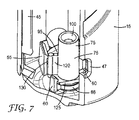
図7に示すように、ステムポスト75は更に、本体15内の所定の位置に、クリップ55、60によって固定されている。クリップ55、60は、ステムポスト上のコーンエッジ130及びステムポスト75上のポストフランジ125とそれぞれ協働する。
As shown in FIG. 7, the
ステムポスト75は、本体15内の用量表示器42(図7には示さず)を支持するウィング120を有して、用量数の表示が表示器視認窓47を通して見えるようになっている。
The stem post 75 has a
本体15上のリブ45によって、キャニスター(図7には示さず)が、本体15内に挿入されたときに位置付けられる。ステムソケット100はキャニスター20のバルブステム22を受け入れ、バルブ21はステムレッジ110(図6に示す)上に支持される。ステムポスト75は細長い管部分76を有する。
コーンクリップ55はコーンエッジ130と協働し、ポストクリップ60はポストフランジ125と協働して、ステムポスト75を本体15内に固定することを支援する。シールリム66が圧入シールの外側部分を形成しており、ステムポスト75の本体15内でのシール嵌合をもたらしている。
The
図8、9及び10に示すのは、ステムポスト75とそのステムソケット100及びステムレッジ110(キャニスター20がアクチュエータ10内に挿入されたときにキャニスター計量バルブ21と接触する)である。膨張チャンバ105は薬剤をキャニスター(図示せず)から受け取り、膨張チャンバ105は移行領域77と流体連通している。移行領域77は底部で開いているが、ステムポスト75がアクチュエータ本体15内の所定の位置にあるときはシールされている。移行領域77は、オリフィス出口85及び噴出部分90と流体連通している。噴出部分90自体は、ステムポスト送達通路91(噴霧コーン95によって部分的に囲まれている)と連絡している。
8, 9 and 10 are a
図11に、ステムポスト75が取り外された状態で後方から見た本体15の切り欠き図を示す。ステムポスト送達通路シート50は、使用時にステムポスト75の噴霧コーン95を支持し、オリフィス出口85の噴出部分90が送達通路25と正しく位置合わせされることを確実にする位置合わせ特徴部を提供する。ポスト支持部材68内の移行凹部64は、使用時にステムポスト75の移行領域77と協働して移行チャンバ70を形成する。
FIG. 11 shows a cutaway view of the
ステムポスト75がアクチュエータ本体のキャニスター開口部11内に挿入されると、圧入シールリング140がポスト支持部材68と接触して、それとぴったり嵌まる。部品とポストシート65のエッジにおける半径との間でわずかでも締めしろがあると、圧入シールリング140はわずかに広がる。更に挿入されると、圧入シールリング140は、引き込み部分とシールリム66の内側最上部において係合する。わずかでも締めしろがあると、圧入シールリング140の復帰変形が生じて、ステムポスト75と本体15との間にシール係合が形成され、製剤又は他の製剤成分(使用時に、用量のわずかな損失も回避するために移行チャンバ70内に収容する必要がある)の漏れが防止される。好ましくは、ステムポストの係合は、ポストシート65が移行領域77の最上部と同一平面で嵌合するように行なわれる。好ましくは、ステムポスト75及び/又はアクチュエータ本体15に位置合わせ特徴部を設けて、オリフィスが送達通路25と正しく位置合わせされることを確実にし、アクチュエータ10内の表面上に噴霧が堆積することを減らす。
When the
当然のことながら、本明細書は前述した実施形態に限定されず、種々の変更を、明細書の原理からも考え方からも逸脱することなく施すことができる。例えば、ステムポストの移行領域は、代替的な実施形態では、平坦であるか又は比較的体積が小さくても良く、アクチュエータ本体の移行凹部は比較的大きくても良い。代替的に、本体移行領域は、移行凹部ではなくて、比較的平坦であるか又は体積が小さくても良い。 As a matter of course, the present specification is not limited to the above-described embodiments, and various changes can be made without departing from the principle and the concept of the specification. For example, the transition area of the stem post may be flat or relatively small in volume and the actuator body transition recess may be relatively large in alternative embodiments. Alternatively, the body transition region may be relatively flat or small in volume rather than a transition recess.
本明細書によるアクチュエータ及び吸入器は、本明細書で説明した任意の特徴部を別個に含んでいても良いし又は任意の他の特徴部と組み合わせて含んでいても良く、このことを必要に応じて他の特徴部の適切な変更を伴って行なっても良い。このことは、当業者にとって容易に明らかであろう。本発明の実施態様の一部を以下の項目[1]−[22]に記載する。
[項目1]
吸入器用アクチュエータであって、
本体と、ステムポストと、前記ステムポストを前記本体内に固定するための固定手段とを含み、
前記本体は、薬剤を送達するための送達通路と、バルブステムを伴う計量バルブを有するキャニスターを挿入するためのキャニスター開口部とを含み、
前記ステムポストは、キャニスターの前記バルブステムを受容するためのステムソケットを含み、薬剤を前記送達通路に放出するためのオリフィスを含み、
前記ステムポストが前記ボディ内に固定されたときに前記ステムポストと前記ボディとが協働で移行チャンバを画定するように前記ステムポストが適応されかつ前記ボディが適応される、吸入器用アクチュエータ。
[項目2]
前記移行チャンバは前記ステムソケット及び前記送達通路と流体連通している、項目1に記載のアクチュエータ。
[項目3]
前記固定手段は、前記ステムポストを前記キャニスター開口部に通して挿入することによって前記ステムポストが前記本体内に固定可能であるように適応されている、項目1又は項目2に記載のアクチュエータ。
[項目4]
前記ステムポストが第1の移行領域を含む、項目1〜3のいずれか一項に記載のアクチュエータ。
[項目5]
前記第1の移行領域は、前記ステムソケットと前記オリフィスとの間に位置している、項目4に記載のアクチュエータ。
[項目6]
前記ステムポストは、計量用量の前記薬剤の少なくとも一部を前記キャニスターから受け取るための膨張チャンバを更に含む、項目1〜5のいずれか一項に記載のアクチュエータ。
[項目7]
前記膨張チャンバは前記ステムソケットと前記移行領域との間に位置している、項目6に記載のアクチュエータ。
[項目8]
前記本体は第2の移行領域を含む、項目1〜7のいずれか一項に記載のアクチュエータ。
[項目9]
前記ステムポストが前記本体内に固定されたときに、前記第1の移行領域と前記第2の移行領域とが前記移行チャンバを画定する、項目8に記載のアクチュエータ。
[項目10]
前記オリフィスは、所定の幅及び所定の長さの噴出部分を有する、項目1〜9のいずれか一項に記載のアクチュエータ。
[項目11]
前記固定手段は少なくとも1つの圧入シールを含む、項目1〜10のいずれか一項に記載のアクチュエータ。
[項目12]
前記少なくとも1つの圧入封止はリング及び溝圧入シールを含む、項目11に記載のアクチュエータ。
[項目13]
前記ステムポストは一体成型品である、項目1〜12のいずれか一項に記載のアクチュエータ。
[項目14]
前記本体は一体成型品である、項目1〜13のいずれか一項に記載のアクチュエータ。
[項目15]
前記送達通路は薬剤の経鼻送達に適応したノーズピースを含む、項目1〜14のいずれか一項に記載のアクチュエータ。
[項目16]
前記本体は、窓、好ましくは表示器及び/又は用量カウンタ視認窓を更に含む、項目1〜15のいずれか一項に記載のアクチュエータ。
[項目17]
用量カウンタを支持するための支持手段を更に含む、項目1〜16のいずれか一項に記載のアクチュエータ。
[項目18]
薬剤を送達するための吸入器であって、項目1〜17のいずれか一項に記載のアクチュエータとキャニスターとを含む吸入器。
[項目19]
吸入器用アクチュエータに対する挿入可能な部品を製造する方法であって、
前記部品を成型するための型であって、雄型の移行特徴部と少なくとも2つの成型ピンとを含む型を用意することと、
前記成型ピンを各成型ピンの端部が前記移行特徴部の表面と接触するように配置することと、
少なくとも第1のポリマーを前記型のキャビティ内に注入することと、を含む方法。
[項目20]
前記の2つの成型ピンは、前記部品の前記膨張チャンバを製造するための第1の成型ピンと、前記部品の前記オリフィスを製造するための第2の成型ピンと、を含む、項目19に記載の方法。
[項目21]
前記移行特徴部は少なくとも第1の表面と第2の表面とを有し、前記第1の成型ピンは前記第1の表面と接触するように配置され、前記第2の成型ピンは前記第2の表面と接触するように配置される項目20に記載の方法。
[項目22]
吸入器用アクチュエータを組み立てる方法であって、
本体と、ステムポストと、前記ステムポストを前記本体内に固定するための固定手段とを用意することであって、前記本体は、第2の移行領域と、薬剤を送達するための送達通路と、バルブステムを伴う計量バルブを有するキャニスターを挿入するためのキャニスター開口部とを含み、前記ステムポストは、第1の移行領域と、キャニスターの前記バルブステムを受け取るためのステムソケットと、薬剤を前記送達通路に放出するためのオリフィスとを含む、用意することと、
前記ステムポストを前記キャニスター開口部に通して前記本体内に挿入することによって前記ステムポストを前記本体内に固定することであって、前記ステムポストが前記本体内に固定されたときに、前記第1の移行領域と前記第2の移行領域とが協働で移行チャンバを画定する、固定することと、を含む方法。
Actuators and inhalers according to the present description may include any feature described herein separately or in combination with any other feature, as required. Accordingly, it may be performed with appropriate change of other features. This will be readily apparent to those skilled in the art. A part of the embodiment of the present invention is described in the following items [1]-[22].
[Item 1]
An inhaler actuator,
A main body, a stem post, and a fixing means for fixing the stem post in the main body,
The body includes a delivery passage for delivering a medicament and a canister opening for inserting a canister having a metering valve with a valve stem;
The stem post includes a stem socket for receiving the valve stem of a canister, and includes an orifice for discharging a drug into the delivery passage;
An inhaler actuator, wherein the stem post is adapted and the body is adapted such that the stem post and the body cooperate to define a transition chamber when the stem post is secured within the body.
[Item 2]
The actuator of claim 1, wherein the transition chamber is in fluid communication with the stem socket and the delivery passage.
[Item 3]
Item 3. The actuator according to item 1 or item 2, wherein the fixing means is adapted so that the stem post can be fixed in the body by inserting the stem post through the canister opening.
[Item 4]
The actuator according to any one of items 1 to 3, wherein the stem post includes a first transition region.
[Item 5]
[Item 6]
6. The actuator of any of items 1-5, wherein the stem post further comprises an expansion chamber for receiving at least a portion of the metered dose of the drug from the canister.
[Item 7]
The actuator of claim 6, wherein the expansion chamber is located between the stem socket and the transition region.
[Item 8]
The actuator according to any one of items 1 to 7, wherein the body includes a second transition region.
[Item 9]
The actuator of claim 8, wherein the first transition region and the second transition region define the transition chamber when the stem post is secured within the body.
[Item 10]
The actuator according to any one of Items 1 to 9, wherein the orifice has an ejection portion having a predetermined width and a predetermined length.
[Item 11]
The actuator according to any one of items 1 to 10, wherein the fixing means includes at least one press-fit seal.
[Item 12]
12. The actuator of
[Item 13]
The actuator according to any one of Items 1 to 12, wherein the stem post is an integrally molded product.
[Item 14]
The actuator according to any one of Items 1 to 13, wherein the main body is an integrally molded product.
[Item 15]
15. The actuator of any one of items 1-14, wherein the delivery passage includes a nosepiece adapted for nasal delivery of a drug.
[Item 16]
16. Actuator according to any of items 1 to 15, wherein the body further comprises a window, preferably a display and / or a dose counter viewing window.
[Item 17]
[Item 18]
An inhaler for delivering a medicine, comprising the actuator according to any one of items 1 to 17 and a canister.
[Item 19]
A method of manufacturing an insertable part for an inhaler actuator comprising:
Providing a mold for molding the part, the mold including a male transition feature and at least two molding pins;
Placing the molding pins such that the end of each molding pin is in contact with the surface of the transition feature;
Injecting at least a first polymer into the mold cavity.
[Item 20]
20. A method according to item 19, wherein the two molding pins include a first molding pin for manufacturing the expansion chamber of the part and a second molding pin for manufacturing the orifice of the part. .
[Item 21]
The transition feature has at least a first surface and a second surface, the first molding pin is disposed in contact with the first surface, and the second molding pin is the second surface. 21. The method according to
[Item 22]
A method of assembling an inhaler actuator,
Providing a body, a stem post, and a securing means for securing the stem post within the body, the body comprising a second transition region, a delivery passage for delivering a medicament, A canister opening for inserting a canister having a metering valve with a valve stem, wherein the stem post has a first transition region, a stem socket for receiving the valve stem of the canister, and a drug Providing an orifice for discharging into the delivery passage;
The stem post is fixed in the main body by inserting the stem post through the canister opening into the main body, and the stem post is fixed when the stem post is fixed in the main body. Securing a transition chamber, wherein one transition region and the second transition region cooperate to define a transition chamber.
Claims (11)
本体と、ステムポストと、前記ステムポストを前記本体内に固定するための固定手段とを含み、
前記本体は、薬剤を送達するための送達通路と、バルブステムを伴う計量バルブを有するキャニスターを挿入するためのキャニスター開口部とを含み、
前記ステムポストは、キャニスターの前記バルブステムを受容するためのステムソケットを含み、薬剤を前記送達通路に放出するためのオリフィスを含み、
前記ステムポストが前記本体内に固定されたときに前記ステムポストと前記本体とが協働で移行チャンバを画定するように前記ステムポストが適応されかつ前記本体が適応される、吸入器用アクチュエータ。 An inhaler actuator,
A main body, a stem post, and a fixing means for fixing the stem post in the main body,
The body includes a delivery passage for delivering a medicament and a canister opening for inserting a canister having a metering valve with a valve stem;
The stem post includes a stem socket for receiving the valve stem of a canister, and includes an orifice for discharging a drug into the delivery passage;
An inhaler actuator, wherein the stem post is adapted and the body is adapted such that the stem post and the body cooperate to define a transition chamber when the stem post is secured within the body .
前記部品を成型するための型であって、雄型の移行特徴部と少なくとも2つの成型ピンとを含む型を用意することと、
前記成型ピンを各成型ピンの端部が前記移行特徴部の表面と接触するように配置することと、
少なくとも第1のポリマーを前記型のキャビティ内に注入することと、を含む方法。 A method for manufacturing an insertable part for the actuator according to any one of claims 1-7 ,
Providing a mold for molding the part, the mold including a male transition feature and at least two molding pins;
Placing the molding pins such that the end of each molding pin is in contact with the surface of the transition feature;
Injecting at least a first polymer into the mold cavity.
本体と、ステムポストと、前記ステムポストを前記本体内に固定するための固定手段とを用意することであって、前記本体は、第2の移行領域と、薬剤を送達するための送達通路と、バルブステムを伴う計量バルブを有するキャニスターを挿入するためのキャニスター開口部とを含み、前記ステムポストは、第1の移行領域と、キャニスターの前記バルブステムを受け取るためのステムソケットと、薬剤を前記送達通路に放出するためのオリフィスとを含む、用意することと、
前記ステムポストを前記キャニスター開口部に通して前記本体内に挿入することによって前記ステムポストを前記本体内に固定することであって、前記ステムポストが前記本体内に固定されたときに、前記第1の移行領域と前記第2の移行領域とが協働で移行チャンバを画定する、固定することと、を含む方法。 A method of assembling an inhaler actuator,
Providing a body, a stem post, and a securing means for securing the stem post within the body, the body comprising a second transition region, a delivery passage for delivering a medicament, A canister opening for inserting a canister having a metering valve with a valve stem, wherein the stem post has a first transition region, a stem socket for receiving the valve stem of the canister, and a drug Providing an orifice for discharging into the delivery passage;
The stem post is fixed in the main body by inserting the stem post through the canister opening into the main body, and the stem post is fixed when the stem post is fixed in the main body. Securing a transition chamber, wherein one transition region and the second transition region cooperate to define a transition chamber.
Applications Claiming Priority (3)
| Application Number | Priority Date | Filing Date | Title |
|---|---|---|---|
| GB1308679.8 | 2013-05-14 | ||
| GBGB1308679.8A GB201308679D0 (en) | 2013-05-14 | 2013-05-14 | Actuator for an inhaler |
| PCT/US2014/037649 WO2014186263A2 (en) | 2013-05-14 | 2014-05-12 | Actuator for an inhaler |
Publications (3)
| Publication Number | Publication Date |
|---|---|
| JP2016518220A JP2016518220A (en) | 2016-06-23 |
| JP2016518220A5 JP2016518220A5 (en) | 2017-06-22 |
| JP6363700B2 true JP6363700B2 (en) | 2018-07-25 |
Family
ID=48700782
Family Applications (1)
| Application Number | Title | Priority Date | Filing Date |
|---|---|---|---|
| JP2016514002A Active JP6363700B2 (en) | 2013-05-14 | 2014-05-12 | Inhaler actuator |
Country Status (8)
| Country | Link |
|---|---|
| US (1) | US10335563B2 (en) |
| EP (1) | EP2996747B2 (en) |
| JP (1) | JP6363700B2 (en) |
| CN (1) | CN105246534B (en) |
| AU (2) | AU2014265711A1 (en) |
| CA (1) | CA2912533C (en) |
| GB (1) | GB201308679D0 (en) |
| WO (1) | WO2014186263A2 (en) |
Families Citing this family (9)
| Publication number | Priority date | Publication date | Assignee | Title |
|---|---|---|---|---|
| MX2018008617A (en) * | 2016-01-25 | 2018-11-19 | Philip Morris Products Sa | Cartridge assembly having an actuation portion. |
| US20170361036A1 (en) * | 2016-06-15 | 2017-12-21 | Virgilant Technologies Limited | Electronic inhaling device |
| GB2553534A (en) | 2016-09-07 | 2018-03-14 | 3M Innovative Properties Co | Trigger mechanism for an inhaler |
| US10556072B2 (en) * | 2017-01-31 | 2020-02-11 | Dunan Microstaq, Inc. | Metering device for a metered dose inhaler |
| GB201707095D0 (en) * | 2017-05-04 | 2017-06-21 | 3M Innovative Properties Co | Inhaler flow control mechanism |
| EP3578218A1 (en) * | 2018-06-08 | 2019-12-11 | Presspart Manufacturing S.A. | Inhaler |
| EP3578216A1 (en) * | 2018-06-08 | 2019-12-11 | Presspart Manufacturing S.A. | Inhaler |
| US11964121B2 (en) | 2021-10-13 | 2024-04-23 | Satio, Inc. | Mono dose dermal patch for pharmaceutical delivery |
| US11877848B2 (en) | 2021-11-08 | 2024-01-23 | Satio, Inc. | Dermal patch for collecting a physiological sample |
Family Cites Families (51)
| Publication number | Priority date | Publication date | Assignee | Title |
|---|---|---|---|---|
| US3001524A (en) | 1956-03-21 | 1961-09-26 | Riker Laboratories Inc | Aerosol dispensing apparatus |
| GB868785A (en) | 1956-10-05 | 1961-05-25 | Sterling Drug Inc | Dispensing heads for aerosol containers |
| US2914222A (en) | 1957-05-20 | 1959-11-24 | Meshberg Philip | Aerosol package |
| US3183907A (en) | 1962-06-25 | 1965-05-18 | Merck & Co Inc | Device for inhalation aerosol |
| GB1085060A (en) | 1963-11-22 | 1967-09-27 | Benger Lab Ltd | Nasal applicators for use with pressurised dispensing containers |
| US3361306A (en) | 1966-03-31 | 1968-01-02 | Merck & Co Inc | Aerosol unit dispensing uniform amounts of a medically active ingredient |
| GB1219090A (en) | 1967-05-22 | 1971-01-13 | Moore Medicinal Products Ltd | Pressurised aerosol dispensers for medicaments |
| GB1402638A (en) | 1972-06-27 | 1975-08-13 | Allen & Hanburys Ltd | Device for dispensing medicaments from a pressurised dispensing container |
| US3913842A (en) | 1973-12-14 | 1975-10-21 | Block Drug Co | Spray head for aerosol can |
| FR2319539A1 (en) | 1975-07-28 | 1977-02-25 | Oreal | PUSH-BUTTON FOR THE DISTRIBUTION OF A HAIR LACQUER CONTAINING A COPOLYMER OF METHYLVINYLETHER AND OF MALEIC ACID MONOESTER |
| GB8319150D0 (en) | 1983-07-15 | 1983-08-17 | Glaxo Group Ltd | Aerosol applicator device |
| GB2170430B (en) * | 1985-01-23 | 1988-05-18 | Ryford Ltd | Spray nozzle |
| GB8622340D0 (en) | 1986-09-17 | 1986-10-22 | Glaxo Group Ltd | Nasal applicator |
| US5119806A (en) | 1987-05-12 | 1992-06-09 | Glaxo Inc. | Inhalation device |
| GB8810898D0 (en) | 1988-05-09 | 1988-06-15 | Bespak Plc | Improvements in dispensing apparatus |
| US5115803A (en) * | 1990-08-31 | 1992-05-26 | Minnesota Mining And Manufacturing Company | Aerosol actuator providing increased respirable fraction |
| GB9419269D0 (en) | 1994-09-23 | 1994-11-09 | Unilever Plc | Aerosol |
| GB2312379B (en) | 1996-04-25 | 1999-11-17 | Bespak Plc | Improved inhalers |
| US5839430A (en) | 1996-04-26 | 1998-11-24 | Cama; Joseph | Combination inhaler and peak flow rate meter |
| AU5549498A (en) | 1997-01-17 | 1998-08-07 | Per Andersen | Aerosol inhaler device |
| SE9701750D0 (en) | 1997-05-12 | 1997-05-12 | Astra Pharma Prod | Inhalation device and method of manufacture thereof |
| IS4516A (en) | 1997-07-01 | 1999-01-02 | Gizurarson Sveinbjörn | New pharmaceutical form |
| WO1999024506A1 (en) | 1997-11-10 | 1999-05-20 | Uniroyal Chemical Company, Inc. | Partially cured thermoplastic elastomers of olefin rubber and polyolefin resin |
| SE9704185D0 (en) | 1997-11-14 | 1997-11-14 | Astra Pharma Prod | Inhalation device |
| SE9802398D0 (en) | 1998-07-03 | 1998-07-03 | Astra Pharma Prod | Inhalation device |
| US6615826B1 (en) | 1999-02-26 | 2003-09-09 | 3M Innovative Properties Company | Slow spray metered dose inhaler |
| FR2794724B1 (en) | 1999-06-10 | 2001-08-24 | Valois Sa | IMPROVED DISTRIBUTOR HEAD AND FLUID PRODUCT DISTRIBUTION DEVICE INCLUDING SUCH HEAD |
| US6367471B1 (en) | 1999-11-01 | 2002-04-09 | Sheffield Pharmaceuticals, Inc. | Internal vortex mechanism for inhaler device |
| GB0002798D0 (en) * | 2000-02-09 | 2000-03-29 | Glaxo Group Ltd | Actuator nozzle for metered dose inhaler |
| GB2366519B (en) | 2000-09-08 | 2002-11-20 | Bespak Plc | Improvements in or relating to dispensing apparatus |
| US6640805B2 (en) | 2001-03-26 | 2003-11-04 | 3M Innovative Properties Company | Metering valve for a metered dose inhaler having improved flow |
| WO2002092154A1 (en) * | 2001-04-26 | 2002-11-21 | New England Pharmaceuticals, Inc. | Metered dose delivery device for liquid and powder agents |
| US6745760B2 (en) | 2001-05-15 | 2004-06-08 | Trudell Medical International | Medicament applicator |
| FR2831841B1 (en) | 2001-11-07 | 2004-09-24 | Valois Sa | FLUID PRODUCT DISPENSING DEVICE |
| AU2003293361A1 (en) * | 2002-12-18 | 2004-07-29 | Glaxo Group Limited | Drug delivery system with vented mouthpiece |
| GB0309354D0 (en) | 2003-04-24 | 2003-06-04 | Glaxo Group Ltd | Nozzle for a nasal inhaler |
| US20040255936A1 (en) * | 2003-04-30 | 2004-12-23 | David Urbanus | Disposable metered dose inhaler with integrated electronic counter |
| GB2398065A (en) | 2003-10-16 | 2004-08-11 | Bespak Plc | Dispensing apparatus |
| US7448385B2 (en) | 2004-06-07 | 2008-11-11 | Purepharm Inc. | Nasal adaptation of an oral inhaler device |
| GB2415388A (en) | 2004-06-24 | 2005-12-28 | Link Holdings Ltd | Medicament dispenser with an insert in the medicament flow path |
| EP2010125B1 (en) * | 2006-04-21 | 2017-01-04 | 3M Innovative Properties Company | Dose counter |
| BRPI0715715A2 (en) | 2006-08-22 | 2014-03-11 | Glaxo Group Ltd | ACTUATOR FOR AN INHALER TO DISTRIBUTE INHALATION MEDICINE, INHALER, AND PARTS KIT |
| CA2661129A1 (en) | 2006-08-22 | 2008-02-28 | Glaxo Group Limited | Actuator for an inhaler |
| WO2008024728A2 (en) | 2006-08-22 | 2008-02-28 | Glaxo Group Limited | Aerosol inhaler with airflow introduced into mouthpiece |
| DE102007063213B3 (en) | 2007-12-20 | 2009-06-18 | Ing. Erich Pfeiffer Gmbh | Discharge device for nasal application |
| CN101251964B (en) * | 2008-03-26 | 2010-06-02 | 深圳市戴文科技有限公司 | Electronic map interest point marking method, system and equipment |
| CN102686261B (en) * | 2009-12-23 | 2014-09-10 | Map药物公司 | Enhanced eductor design |
| US20130087142A1 (en) * | 2010-03-17 | 2013-04-11 | Sun Pharma Advanced Research Company Ltd. | Metered dose inhaler |
| GB201006759D0 (en) | 2010-04-23 | 2010-06-09 | 3M Innovative Properties Co | An inhaler |
| US20120085345A1 (en) * | 2010-10-12 | 2012-04-12 | Teva Branded Pharmaceutical Products R&D, Inc. | Nasal spray device |
| WO2013167429A1 (en) * | 2012-05-09 | 2013-11-14 | Boehringer Ingelheim International Gmbh | Atomizer |
-
2013
- 2013-05-14 GB GBGB1308679.8A patent/GB201308679D0/en not_active Ceased
-
2014
- 2014-05-12 JP JP2016514002A patent/JP6363700B2/en active Active
- 2014-05-12 CN CN201480027826.5A patent/CN105246534B/en active Active
- 2014-05-12 AU AU2014265711A patent/AU2014265711A1/en not_active Abandoned
- 2014-05-12 WO PCT/US2014/037649 patent/WO2014186263A2/en active Application Filing
- 2014-05-12 EP EP14797022.2A patent/EP2996747B2/en active Active
- 2014-05-12 US US14/890,495 patent/US10335563B2/en active Active
- 2014-05-12 CA CA2912533A patent/CA2912533C/en active Active
-
2017
- 2017-05-25 AU AU2017203489A patent/AU2017203489B2/en active Active
Also Published As
| Publication number | Publication date |
|---|---|
| EP2996747B2 (en) | 2022-12-07 |
| WO2014186263A2 (en) | 2014-11-20 |
| US10335563B2 (en) | 2019-07-02 |
| EP2996747B1 (en) | 2020-05-20 |
| AU2014265711A1 (en) | 2015-11-26 |
| JP2016518220A (en) | 2016-06-23 |
| EP2996747A4 (en) | 2017-01-18 |
| EP2996747A2 (en) | 2016-03-23 |
| US20160121060A1 (en) | 2016-05-05 |
| WO2014186263A3 (en) | 2015-01-29 |
| CA2912533C (en) | 2021-06-08 |
| GB201308679D0 (en) | 2013-06-26 |
| CN105246534A (en) | 2016-01-13 |
| CA2912533A1 (en) | 2014-11-20 |
| AU2017203489A1 (en) | 2017-06-15 |
| CN105246534B (en) | 2018-09-18 |
| AU2017203489B2 (en) | 2019-06-20 |
Similar Documents
| Publication | Publication Date | Title |
|---|---|---|
| JP6363700B2 (en) | Inhaler actuator | |
| US8584668B2 (en) | Inhalation device | |
| JP4546699B2 (en) | Spray equipment | |
| CN110366438B (en) | Atomizer unit with directly connectable ampoule | |
| JP5806677B2 (en) | Device and method comprising an adjustable stepped mouthpiece for inhalant aerosol delivery | |
| BR112014025878B1 (en) | METHOD FOR SUPPLYING A DOSED QUANTITY OF A LIQUID MEDICINE TO AN AEROSOLIZATION DEVICE, AND, AEROSOLIZATION SYSTEM | |
| DK3062855T3 (en) | NOZZLE AND INHALATOR | |
| WO2015095341A1 (en) | Actuator for an inhaler | |
| US20170007788A1 (en) | Actuator and Nose Piece for a Nasal Inhaler | |
| JP4791372B2 (en) | Metered dispenser and its assembly | |
| AU2015264908A1 (en) | Nebuliser for Ventilation Machines and a Ventilation Machine Comprising such a Nebuliser | |
| EP3565489B1 (en) | Device for administration of compositions to the eustachian tube | |
| ES2957317T3 (en) | Inhaler | |
| EP3578217B1 (en) | Inhaler | |
| EP3578216A1 (en) | Inhaler | |
| CN220676177U (en) | Inhaler and respiratory indicator for displaying respiratory action of the inhaler | |
| ITBO20090132A1 (en) | DEVICE FOR NEBULIZATION OF SUBSTANCES IN A VENTILATION CIRCUIT |
Legal Events
| Date | Code | Title | Description |
|---|---|---|---|
| A521 | Request for written amendment filed |
Free format text: JAPANESE INTERMEDIATE CODE: A523 Effective date: 20170509 |
|
| A621 | Written request for application examination |
Free format text: JAPANESE INTERMEDIATE CODE: A621 Effective date: 20170509 |
|
| A131 | Notification of reasons for refusal |
Free format text: JAPANESE INTERMEDIATE CODE: A131 Effective date: 20180220 |
|
| A977 | Report on retrieval |
Free format text: JAPANESE INTERMEDIATE CODE: A971007 Effective date: 20180216 |
|
| A521 | Request for written amendment filed |
Free format text: JAPANESE INTERMEDIATE CODE: A523 Effective date: 20180515 |
|
| TRDD | Decision of grant or rejection written | ||
| A01 | Written decision to grant a patent or to grant a registration (utility model) |
Free format text: JAPANESE INTERMEDIATE CODE: A01 Effective date: 20180529 |
|
| A61 | First payment of annual fees (during grant procedure) |
Free format text: JAPANESE INTERMEDIATE CODE: A61 Effective date: 20180628 |
|
| R150 | Certificate of patent or registration of utility model |
Ref document number: 6363700 Country of ref document: JP Free format text: JAPANESE INTERMEDIATE CODE: R150 |
|
| S111 | Request for change of ownership or part of ownership |
Free format text: JAPANESE INTERMEDIATE CODE: R313113 |
|
| R350 | Written notification of registration of transfer |
Free format text: JAPANESE INTERMEDIATE CODE: R350 |
|
| R250 | Receipt of annual fees |
Free format text: JAPANESE INTERMEDIATE CODE: R250 |
|
| RD02 | Notification of acceptance of power of attorney |
Free format text: JAPANESE INTERMEDIATE CODE: R3D02 |
|
| R250 | Receipt of annual fees |
Free format text: JAPANESE INTERMEDIATE CODE: R250 |
|
| R250 | Receipt of annual fees |
Free format text: JAPANESE INTERMEDIATE CODE: R250 |