EP2996747B2 - Actuator for an inhaler - Google Patents
Actuator for an inhaler Download PDFInfo
- Publication number
- EP2996747B2 EP2996747B2 EP14797022.2A EP14797022A EP2996747B2 EP 2996747 B2 EP2996747 B2 EP 2996747B2 EP 14797022 A EP14797022 A EP 14797022A EP 2996747 B2 EP2996747 B2 EP 2996747B2
- Authority
- EP
- European Patent Office
- Prior art keywords
- stem
- actuator
- post
- canister
- stem post
- Prior art date
- Legal status (The legal status is an assumption and is not a legal conclusion. Google has not performed a legal analysis and makes no representation as to the accuracy of the status listed.)
- Active
Links
Images


Classifications
-
- A—HUMAN NECESSITIES
- A61—MEDICAL OR VETERINARY SCIENCE; HYGIENE
- A61M—DEVICES FOR INTRODUCING MEDIA INTO, OR ONTO, THE BODY; DEVICES FOR TRANSDUCING BODY MEDIA OR FOR TAKING MEDIA FROM THE BODY; DEVICES FOR PRODUCING OR ENDING SLEEP OR STUPOR
- A61M15/00—Inhalators
- A61M15/009—Inhalators using medicine packages with incorporated spraying means, e.g. aerosol cans
-
- A—HUMAN NECESSITIES
- A61—MEDICAL OR VETERINARY SCIENCE; HYGIENE
- A61M—DEVICES FOR INTRODUCING MEDIA INTO, OR ONTO, THE BODY; DEVICES FOR TRANSDUCING BODY MEDIA OR FOR TAKING MEDIA FROM THE BODY; DEVICES FOR PRODUCING OR ENDING SLEEP OR STUPOR
- A61M15/00—Inhalators
- A61M15/0001—Details of inhalators; Constructional features thereof
- A61M15/0021—Mouthpieces therefor
- A61M15/0025—Mouthpieces therefor with caps
- A61M15/0026—Hinged caps
-
- A—HUMAN NECESSITIES
- A61—MEDICAL OR VETERINARY SCIENCE; HYGIENE
- A61M—DEVICES FOR INTRODUCING MEDIA INTO, OR ONTO, THE BODY; DEVICES FOR TRANSDUCING BODY MEDIA OR FOR TAKING MEDIA FROM THE BODY; DEVICES FOR PRODUCING OR ENDING SLEEP OR STUPOR
- A61M15/00—Inhalators
- A61M15/0065—Inhalators with dosage or measuring devices
- A61M15/0068—Indicating or counting the number of dispensed doses or of remaining doses
- A61M15/007—Mechanical counters
- A61M15/0071—Mechanical counters having a display or indicator
- A61M15/0075—Mechanical counters having a display or indicator on a disc
-
- A—HUMAN NECESSITIES
- A61—MEDICAL OR VETERINARY SCIENCE; HYGIENE
- A61M—DEVICES FOR INTRODUCING MEDIA INTO, OR ONTO, THE BODY; DEVICES FOR TRANSDUCING BODY MEDIA OR FOR TAKING MEDIA FROM THE BODY; DEVICES FOR PRODUCING OR ENDING SLEEP OR STUPOR
- A61M15/00—Inhalators
- A61M15/08—Inhaling devices inserted into the nose
-
- A—HUMAN NECESSITIES
- A61—MEDICAL OR VETERINARY SCIENCE; HYGIENE
- A61M—DEVICES FOR INTRODUCING MEDIA INTO, OR ONTO, THE BODY; DEVICES FOR TRANSDUCING BODY MEDIA OR FOR TAKING MEDIA FROM THE BODY; DEVICES FOR PRODUCING OR ENDING SLEEP OR STUPOR
- A61M2207/00—Methods of manufacture, assembly or production
Definitions
- the present invention relates to actuators for metered dose inhalers and to a method of assembling an actuator for an inhaler.
- Pressurized metered dose inhalers may be used for delivering medication in the form of aerosols to patients.
- the route of delivery of the medicament using such inhalers may be oral or nasal.
- Such an inhaler commonly comprises a canister containing the medicament aerosol formulation, and an actuator with a delivery passage.
- the canister contains the aerosol formulation, either as a solution or suspension, in the form of one or more drugs and propellant, and optionally excipients, selected from co-solvents, surfactants, stabilizing substances (for chemical or physical stability) and flavourings.
- the canister also comprises a metering valve arranged to deliver a metered dose of the medicament on actuation of the inhaler.
- the actuator typically comprises a housing, generally made of a plastic material, within which the canister is located. A portion of the canister will usually project above the actuator housing.
- the actuator has a delivery passage in the form of a mouthpiece that is placed in the patient's mouth and through which the medicament passes on being dispensed.
- the patient places the mouthpiece in their mouth and breathes in, creating an air flow from the actuator through the mouthpiece and into the mouth and lungs.
- the patient actuates dispensation of the medicament from the canister.
- Actuation may occur as a result of inhalation by the patient or the patient may manually actuate the inhaler, for example, by depressing the projecting portion of the canister further into the housing.
- Nasal actuators operate in a similar fashion, but instead of a mouthpiece the actuator is provided with a nosepiece for delivery of the medicament to the nasal passages. In the case of nasal medicament delivery, there is not a need for the concurrent inhalation of air, however.
- WO-A-98/031411 discloses an aerosol inhalation device that is manually operated and comprises a holding part for receiving an aerosol container with a valve and outlet tip, an inspiratory part and a member for passage of aerosol.
- US-A-2003/0089368 discloses nozzles for aerosol propellant systems, and more particularly aerosolization spray nozzles for metered dose inhalers.
- US-B- 3,361,306 discloses an aerosol device for dispensing a liquid containing a medically active ingredient dissolved or suspended therein.
- WO-A-99/25407 discloses an actuator for an inhaler for administering medicament by inhalation.
- GB-A-2,143,283 discloses applicators for dispensing medicaments from a pressurised dispensing container.
- GB-A-2,170,430 is concerned with improvements relating to spray nozzles, particularly of the kind that are used to dispense a fine spray of liquid.
- GB-A-1,021,739 relates to a device for use in inhalation therapy with aerosols.
- GB-A-2,366,519 discloses a dispensing apparatus for use with pressurised dispensing containers and, in particular, an apparatus for dispensing orally inhaled medicinal products in aerosol form.
- US2010/224185 discloses an actuator for an inhaler for delivering medicament by inhalation
- US2012/085345 discloses a nasal spray device for the delivery of a pharmaceutical formulation to the nasal cavity in metered doses.
- GB2398065 discloses a dispenser for metered dispensation of a medicament.
- GB2415388 discloses a delivery device for dispensing a medicament contained in a pressurised dispensing container to a patient.
- US2011155129 discloses an educator for a breath-actuated inhalation device.
- actuators do not, however, take account of the need to accommodate various designs of canister valve.
- Actuators in the documents listed above do not take account of the need to provide devices to improve the assurance for patients in their use of inhalers, for example, dose indicators. Furthermore, it may be complex and costly to manufacture actuators to the required tolerances and quality.
- the present invention is defined by the appended claims.
- the present invention accordingly provides an actuator for an inhaler, the actuator comprising a body (preferably an elongate body), a stem post and fixing means for fixing the stem post in the body, wherein the body comprises a delivery passage for delivery of a medicament and a canister opening for insertion of a canister having a metering valve with a valve stem, the stem post comprises a stem socket for receiving the valve stem of the canister and comprises an orifice for discharging the medicament to the delivery passage, and wherein the stem post is adapted and the body is adapted so that the stem post and body cooperate to define a transition chamber when the stem post is fixed in the body, the transition chamber being situated between the stem socket and the orifice and in fluid communication with the stem socket and the delivery passage.
- Arranging the stem post and body to define a transition chamber is advantageous because it facilitates manufacture of an actuator with a relatively longer orifice and/or with a relatively longer, optional, expansion chamber.
- the possibility of having a longer orifice allows selection of appropriate characteristics of the spray exiting from the orifice. It is important to optimise the spray characteristics for medicament delivery, and for patient comfort particularly in nasal drug delivery applications.
- the longer, optional, expansion chamber allows more space to incorporate other components in the actuator (e.g. a dose counter).
- the longer orifice and/or the longer, optional, expansion chamber are of particular benefit when the spray is directed at an upward angle for intranasal administration.
- the transition chamber is preferably in fluid communication between the stem socket and the orifice.
- the orifice and the expansion chamber are the only communicating ports in the transition chamber.
- the fixing means are adapted so that the stem post is fixable in the body by insertion of the stem post through the canister opening.
- the actuator is provided with fixing means that enable the stem post component to be fixed by insertion through the canister opening, this assists in the formation of a good seal between the actuator body component and the actuator stem post component.
- Such a seal may be further improved as the patient depresses the canister.
- alignment of the orifice with the delivery passage is also much improved.
- the stem post may be adapted to be fixable solely by the action of insertion.
- additional fixing means such as clips, adhesives and/or welding portions may also be used to fix the stem post and the body. Welding may be heat, ultrasonic and/or laser welding.
- intake of air for patient inhalation is provided through the canister opening.
- the stem post comprises a first transition region that is situated between the stem socket and the orifice.
- the stem post further comprises an expansion chamber for receiving at least a portion of a metered dose of the medicament from the canister.
- the expansion chamber will be situated between the stem socket and first transition region and is preferably in fluid communication with the stem socket and first transition region.
- the body comprises a second transition region. It is preferred if the second transition region comprises a transition recess. More preferably the second transition region or transition recess is situated in a post seat extending upwardly from the base of the body.
- the stem post and body are preferably adapted so that the first transition region forms part of the transition chamber when the stem post is fixed to the body and/or the second transition region (e.g. the transition recess) forms part of the transition chamber when the stem post is fixed to the body.
- first transition region and the second transition region define (preferably cooperate to define) the transition chamber when the stem post is fixed in the body.
- the orifice preferably, comprises a jet portion of predetermined width and predetermined length, that preferably extends from the transition chamber to the orifice outlet.
- the predetermined width may be in the range 0.1 mm to 1.5 mm.
- the predetermined length may be in the range 0.05 mm to 5 mm, preferably 0.4 mm to 3 mm.
- the orifice may be generally of any cross sectional shape (e.g. oval, rectangular) but is preferably generally circular.
- the fixing means preferably comprises at least one press fit seal which may be a ring and groove press fit seal.
- the ring portion of a ring and groove press fit seal will be on the stem post, with the groove situated in the actuator body.
- the ring may alternatively be on the body with the groove on the stem post.
- the press fit seal preferably forms an interference fit seal when engaged.
- the fixing means may comprise an adhesive portion (where an adhesive has been used to fix the stem post and body) and/or a welded portion (where a welding process has been used to fix the stem post and body).
- the welded portion may be an ultrasonic, laser and/or heat welded portion.
- the fixing means may additionally comprise at least one clip.
- the fixing means is preferably tamper-proof, or advantageously at least tamper-evident to discourage a patient from separating the stem post from the actuator body.
- the body and/or stem post may further comprise alignment features, for example asymmetric lugs, keying features, cradles, clips or flat surfaces that in combination with other alignment features define a position of alignment and engagement.
- alignment features for example asymmetric lugs, keying features, cradles, clips or flat surfaces that in combination with other alignment features define a position of alignment and engagement.
- the stem post may be a unitary moulding (i.e. the stem post may be or is produced by moulding in one piece). This is particularly advantageous because it leads to manufacturing efficiency.
- it has been difficult to consistently mould an actuator in one piece, at least partly because of the need for tight tolerances and particularly minimal moulding flash.
- This has previously been a particular problem in the case of nasal inhalers where there is an acute angle between the stem socket/expansion chamber and delivery passage of the actuator.
- this problem is addressed by the use of a separate but fixable stem post (usually of a smaller size than the assembled actuator), which enables higher tolerances to be achieved in the mould with a significant reduction in flash.
- the stem socket may be adapted to receive a particular design of valve and/or design of valve stem.
- the whole actuator would have to be re-designed to accommodate a different design of valve, in the present specification a much smaller piece is required to be moulded to take account of a differing design. Little or no change need usually be made to the body, with advantages in manufacturing efficiency and inventory control and reduction in tooling cost.
- the body is a unitary moulding (i.e. the body may be or is produced by moulding in one piece).
- the actuator may be a nasal actuator. Consequently, the delivery passage may comprise a nose piece adapted for nasal delivery of the medicament.
- the nosepiece is preferably angled upwardly at an acute angle with respect to the long axis of the body, preferably at 85° or less, more preferably at 75° or less or 70° or less, most preferably at about 66°.
- the body may further comprise a window, preferably an indicator viewing window.
- the indicator viewing window is particularly useful for display of a dose indication or a dose count if the actuator further comprises a dose indicator or a dose counter.
- the stem post further comprises supporting means (i.e. first supporting means) for supporting a dose indicator or a dose counter.
- supporting means may be, for example wing portions on the stem post.
- the body may alternatively or additionally comprise second supporting means for supporting a dose indicator or dose counter.
- an inhaler comprising an actuator as discussed in relation to the first aspect or the second aspect, and a canister.
- the actuator may be produced by moulding, preferably injection moulding.
- the present invention provides a method of assembling an actuator for an inhaler, the method comprising providing a body, a stem post and fixing means for fixing the stem post in the body, wherein the body comprises a second transition region, a delivery passage for delivery of a medicament and a canister opening for insertion of a canister having a metering valve with a valve stem, and wherein the stem post comprises a first transition region, a stem socket for receiving the valve stem of the canister, and an orifice for discharging the medicament to the delivery passage, and inserting the stem post through the canister opening into the body thereby fixing the stem post in the body and wherein the first transition region and the second transition region define (i.e. cooperate to define) a transition chamber when the stem post is fixed in the body, the transition chamber being situated between the stem socket and the orifice and in fluid communication with the stem socket and the delivery passage.
- inhaler means a device for delivery of a medicament in fluid (or powder) form either orally or nasally and does not imply that the device requires inhalation on the part of the patient during delivery. It is known that a medicament may be delivered successfully to the nasal passages by an inhaler without the need for the patient to inhale.
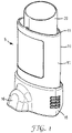
- Figure 1 illustrates, in perspective view, a pressurised metered dose inhaler 5 comprising a canister 20 and an actuator 10.
- the canister 20 is pressurised and holds medicament for delivery via the actuator 10.
- the actuator 10 has a generally elongate actuator body 15 that acts as a housing for the canister 20.
- the canister 20 is inserted into the canister opening 11 at the top portion of the actuator 10.
- the inhaler 5 is a nasal inhaler, having a nose piece (see Figure 4 ) covered by a cap 16.
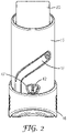
- Figure 2 shows, in a rear view, the actuator body 15, the actuator cap 16, and the canister 20.
- the body 15 has a cap track 17 arranged to guide the cap 16 from a closed position in which the cap 16 covers the nose piece (the position as shown in Figures 1 and 2 ) to an open position (not shown) in which the nose piece 30 is uncovered.
- the body 15 has a viewing window 47 through which the display of a dose indicator 42 is visible.
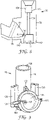
- FIG. 3 shows a vertical section through the inhaler 5.
- the actuator 10 comprises the body 15 and a separate unitary moulded stem post 75.
- the stem post 75 is fixed in the body 15 and the stem post 75 has a stem socket 100 for receiving the canister valve stem 22 of the canister metering valve 21.
- the patient would displace cap 16 from the nose piece 30, insert the nose piece 30 into a nostril and exert pressure on the top of the canister 20.
- This moves the canister 20 into the body 15 of the actuator and presses the canister valve stem 22 against the stem post 75, resulting in the canister metering valve 21 opening and releasing a metered dose of medicament into an expansion chamber 105 within the stem post 75.
- the expansion chamber 105 is in fluid communication with a delivery passage 25 in the body 15 so the medicament is delivered through the delivery passage 25 and out of the nose piece 30 into the patient's nostril.
- a dose indicator 42 is situated at the lower rear portion of the body 15 so that its indicia are visible through the indicator window 47. The dose indicator 42 is so arranged that movement of the canister 20 in use indexes the dose indicator 42.
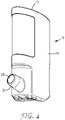
- Figure 4 shows the actuator 10 with the cap 16 and canister 20 removed.
- the nose piece 30 is angled upwardly at an acute angle with respect to the long axis of the body 15 for convenient insertion into the nostril of a patient.
- the nose piece 30 has a delivery passage 25 through which the medicament is delivered.
- Figure 5 shows a vertical section through an actuator 10 as illustrated in Figure 4 .
- Figure 6 shows a section through the lower portion of the actuator 10.
- the dose indicator 42 shown in Figure 3
- Figure 5 also shows ribs 45 that locate the canister 20 in the correct position in the body 15 of the actuator 10.
- the delivery passage 25 in the nose piece 30 is arranged to receive doses of medicament through a stem post delivery passage 91, partly defined by the spray cone 95 of the stem post 75.
- the stem post 75 is a separate moulding fixed in the body 15 with a press fit sealing ring 140 in press fit sealing groove 67 of the body 15.
- the stem post delivery passage 91 is in fluid communication with an orifice outlet 85 in the stem post 75.
- the orifice outlet 85 is in fluid communication through a jet portion 90 with a transition chamber 70.
- the jet portion 90 is of predetermined width and predetermined length and may be in the form of a cylindrical tube of diameter 0.1 to 1.5 mm and of length 0.05 to 5 mm, the length usually being 0.4 mm to 3 mm.
- the transition chamber 70 is formed by parts of both the body 15 and the stem post 75, in particular, by a body transition region formed by the configuration of a post support 68 and post seat 65 together with the transition region 77 (not shown in Figure 6 ; see Figures 8 and 10 ) of the stem post 75.
- a metered dose of medicament is delivered from the valve 21 of the canister 20 (not shown in Figure 6 ) through the expansion chamber 105 of the stem post 75, into the transition chamber 70 formed by the interaction/cooperation of the stem post transition region 77 and a body transition region (including transition recess 64) (see Figure 11 ) in the post support 68 of the body 15, and out of the orifice outlet 85 via the jet portion 90. From the orifice outlet 85, the dose is delivered through the spray cone 95, the stem post delivery passage 91 and the delivery passage 25.
- the stem post 75 is additionally fixed in position in the body 15 through clips 55, 60 cooperating respectively with a cone edge 130 on the stem post and a post flange 125 on the stem post 75.
- the stem post 75 has wings 120 to support a dose indicator 42 (not shown in Figure 7 ) in the body 15, such that a display of the dose number is visible through the indicator viewing window 47.
- Ribs 45 on the body 15 locate the canister (not shown in Figure 7 ) when inserted in the body 15.
- the stem socket 100 accepts the valve stem 22 of the canister 20 and the valve 21 is supported on a stem ledge 110 (shown in Figure 6 ).
- the stem post 75 has an elongate tube portion 76.
- the cone clips 55 cooperate with the cone edge 130 and the post clips 60 cooperate with the post flange 125 to help fix the stem post 75 in the body 15.
- a sealing rim 66 forming the outer part of the press fit seal provides a sealing fit of the stem post 75 in the body 15.
- Figures 8, 9 and 10 show the stem post 75 with its stem socket 100 and stem ledge 110 (which contacts the canister metering valve 21 when a canister 20 is inserted in the actuator 10).
- the expansion chamber 105 receives medicament from the canister (not shown) and the expansion chamber 105 is in fluid communication with the transition region 77.
- the transition region 77 is open at the bottom but is sealed when the stem post 75 is in position in the actuator body 15.
- the transition region 77 is in fluid communication with the orifice outlet 85 and the jet portion 90 which in turn communicates with the stem post delivery passage 91 that is partially enclosed by the spray cone 95.
- Figure 11 shows a cut away view of the body 15 from the rear with the stem post 75 removed.
- the stem post delivery passage seat 50 supports the spray cone 95 of the stem post 75 when in use, and provides an alignment feature to ensure that the jet portion 90 of the orifice outlet 85 is aligned correctly with the delivery passage 25.
- the transition recess 64 in the post support 68 cooperates in use with the transition region 77 of the stem post 75 to form the transition chamber 70.
- the press fit sealing ring 140 contacts the post support 68, with which it is a tight fit. Any interference between the parts and the radius at the edge of the post seat 65 cause the press fit sealing ring 140 to splay slightly. Upon further insertion, the press fit sealing ring 140 engages the lead-in portion at the inside top portion of the sealing rim 66. Any interference causes a return deformation of the press fit sealing ring 140, and provides a sealing engagement between the stem post 75 and the body 15 which prevents leakage of formulation or other formulation components that, in use, need to be contained within the transition chamber 70 to avoid any loss of dose.
- the stem post is engaged such that the post seat 65 fits flush with the top of the transition region 77.
- the stem post 75 and/or the actuator body 15 is provided with alignment features to ensure that the orifice is correctly aligned with the delivery passage 25 to reduce deposition of spray on surfaces within the actuator 10.
- the transition region of the stem post may in an alternative embodiment be flat or relatively small in volume and the transition recess of the actuator body may be relatively large.
- the body transition region may not be a transition recess but relatively flat or of low volume.
- Actuators and inhalers according to the specification may include any feature described herein separately or in combination with any other feature(s), if necessary with appropriate modification of other features, as would be readily apparent to the skilled person.
Description
- This application claims priority to United Kingdom Patent Application No.
1308679.8, filed May 14, 2013 - The present invention relates to actuators for metered dose inhalers and to a method of assembling an actuator for an inhaler.
- Pressurized metered dose inhalers (pMDI) may be used for delivering medication in the form of aerosols to patients. The route of delivery of the medicament using such inhalers may be oral or nasal.
- Such an inhaler commonly comprises a canister containing the medicament aerosol formulation, and an actuator with a delivery passage. The canister contains the aerosol formulation, either as a solution or suspension, in the form of one or more drugs and propellant, and optionally excipients, selected from co-solvents, surfactants, stabilizing substances (for chemical or physical stability) and flavourings. The canister also comprises a metering valve arranged to deliver a metered dose of the medicament on actuation of the inhaler.
- The actuator typically comprises a housing, generally made of a plastic material, within which the canister is located. A portion of the canister will usually project above the actuator housing.
- In oral inhalers the actuator has a delivery passage in the form of a mouthpiece that is placed in the patient's mouth and through which the medicament passes on being dispensed. The patient places the mouthpiece in their mouth and breathes in, creating an air flow from the actuator through the mouthpiece and into the mouth and lungs. At the same time the patient actuates dispensation of the medicament from the canister. Actuation may occur as a result of inhalation by the patient or the patient may manually actuate the inhaler, for example, by depressing the projecting portion of the canister further into the housing. Nasal actuators operate in a similar fashion, but instead of a mouthpiece the actuator is provided with a nosepiece for delivery of the medicament to the nasal passages. In the case of nasal medicament delivery, there is not a need for the concurrent inhalation of air, however.
-
WO-A-98/031411 -
US-A-2003/0089368 discloses nozzles for aerosol propellant systems, and more particularly aerosolization spray nozzles for metered dose inhalers. -
US-B- 3,361,306 discloses an aerosol device for dispensing a liquid containing a medically active ingredient dissolved or suspended therein. -
WO-A-99/25407 -
GB-A-2,143,283 -
GB-A-2,170,430 -
GB-A-1,021,739 -
GB-A-2,366,519 -
US2010/224185 discloses an actuator for an inhaler for delivering medicament by inhalation -
US2012/085345 discloses a nasal spray device for the delivery of a pharmaceutical formulation to the nasal cavity in metered doses. -
GB2398065 -
GB2415388 -
US2011155129 discloses an educator for a breath-actuated inhalation device. - Known actuators do not, however, take account of the need to accommodate various designs of canister valve. Actuators in the documents listed above do not take account of the need to provide devices to improve the assurance for patients in their use of inhalers, for example, dose indicators. Furthermore, it may be complex and costly to manufacture actuators to the required tolerances and quality. The present invention is defined by the appended claims.
- In a first aspect, the present invention accordingly provides an actuator for an inhaler, the actuator comprising a body (preferably an elongate body), a stem post and fixing means for fixing the stem post in the body, wherein the body comprises a delivery passage for delivery of a medicament and a canister opening for insertion of a canister having a metering valve with a valve stem, the stem post comprises a stem socket for receiving the valve stem of the canister and comprises an orifice for discharging the medicament to the delivery passage, and wherein the stem post is adapted and the body is adapted so that the stem post and body cooperate to define a transition chamber when the stem post is fixed in the body, the transition chamber being situated between the stem socket and the orifice and in fluid communication with the stem socket and the delivery passage.
- Arranging the stem post and body to define a transition chamber is advantageous because it facilitates manufacture of an actuator with a relatively longer orifice and/or with a relatively longer, optional, expansion chamber. The possibility of having a longer orifice allows selection of appropriate characteristics of the spray exiting from the orifice. It is important to optimise the spray characteristics for medicament delivery, and for patient comfort particularly in nasal drug delivery applications. The longer, optional, expansion chamber allows more space to incorporate other components in the actuator (e.g. a dose counter). The longer orifice and/or the longer, optional, expansion chamber are of particular benefit when the spray is directed at an upward angle for intranasal administration.
- The transition chamber is preferably in fluid communication between the stem socket and the orifice.
- Preferably, the orifice and the expansion chamber are the only communicating ports in the transition chamber.
- Preferably, the fixing means are adapted so that the stem post is fixable in the body by insertion of the stem post through the canister opening. This is advantageous, because it has surprisingly been found that when the actuator is provided with fixing means that enable the stem post component to be fixed by insertion through the canister opening, this assists in the formation of a good seal between the actuator body component and the actuator stem post component. Such a seal may be further improved as the patient depresses the canister. Surprisingly, alignment of the orifice with the delivery passage is also much improved.
- The stem post may be adapted to be fixable solely by the action of insertion. In some embodiments additional fixing means such as clips, adhesives and/or welding portions may also be used to fix the stem post and the body. Welding may be heat, ultrasonic and/or laser welding.
- Preferably, intake of air for patient inhalation is provided through the canister opening.
- Preferably, the stem post comprises a first transition region that is situated between the stem socket and the orifice.
- Preferably, the stem post further comprises an expansion chamber for receiving at least a portion of a metered dose of the medicament from the canister. Usually, the expansion chamber will be situated between the stem socket and first transition region and is preferably in fluid communication with the stem socket and first transition region.
- Preferably, the body comprises a second transition region. It is preferred if the second transition region comprises a transition recess. More preferably the second transition region or transition recess is situated in a post seat extending upwardly from the base of the body. The stem post and body are preferably adapted so that the first transition region forms part of the transition chamber when the stem post is fixed to the body and/or the second transition region (e.g. the transition recess) forms part of the transition chamber when the stem post is fixed to the body.
- Thus, in a preferred embodiment, the first transition region and the second transition region define (preferably cooperate to define) the transition chamber when the stem post is fixed in the body.
- The orifice, preferably, comprises a jet portion of predetermined width and predetermined length, that preferably extends from the transition chamber to the orifice outlet. The predetermined width may be in the range 0.1 mm to 1.5 mm. The predetermined length may be in the range 0.05 mm to 5 mm, preferably 0.4 mm to 3 mm. The orifice may be generally of any cross sectional shape (e.g. oval, rectangular) but is preferably generally circular.
- The fixing means preferably comprises at least one press fit seal which may be a ring and groove press fit seal. Typically, the ring portion of a ring and groove press fit seal will be on the stem post, with the groove situated in the actuator body. However, the ring may alternatively be on the body with the groove on the stem post. The press fit seal preferably forms an interference fit seal when engaged.
- The fixing means may comprise an adhesive portion (where an adhesive has been used to fix the stem post and body) and/or a welded portion (where a welding process has been used to fix the stem post and body). The welded portion may be an ultrasonic, laser and/or heat welded portion.
- The fixing means may additionally comprise at least one clip.
- The fixing means is preferably tamper-proof, or advantageously at least tamper-evident to discourage a patient from separating the stem post from the actuator body.
- Preferably, the body and/or stem post may further comprise alignment features, for example asymmetric lugs, keying features, cradles, clips or flat surfaces that in combination with other alignment features define a position of alignment and engagement.
- The stem post may be a unitary moulding (i.e. the stem post may be or is produced by moulding in one piece). This is particularly advantageous because it leads to manufacturing efficiency. Previously, it has been difficult to consistently mould an actuator in one piece, at least partly because of the need for tight tolerances and particularly minimal moulding flash. This has previously been a particular problem in the case of nasal inhalers where there is an acute angle between the stem socket/expansion chamber and delivery passage of the actuator. In the present invention, this problem is addressed by the use of a separate but fixable stem post (usually of a smaller size than the assembled actuator), which enables higher tolerances to be achieved in the mould with a significant reduction in flash. A further benefit of the actuator of the present invention is that the stem socket may be adapted to receive a particular design of valve and/or design of valve stem. Thus, whereas in known actuators the whole actuator would have to be re-designed to accommodate a different design of valve, in the present specification a much smaller piece is required to be moulded to take account of a differing design. Little or no change need usually be made to the body, with advantages in manufacturing efficiency and inventory control and reduction in tooling cost.
- It is advantageous if the body is a unitary moulding (i.e. the body may be or is produced by moulding in one piece).
- The actuator may be a nasal actuator. Consequently, the delivery passage may comprise a nose piece adapted for nasal delivery of the medicament. The nosepiece is preferably angled upwardly at an acute angle with respect to the long axis of the body, preferably at 85° or less, more preferably at 75° or less or 70° or less, most preferably at about 66°.
- The body may further comprise a window, preferably an indicator viewing window. The indicator viewing window is particularly useful for display of a dose indication or a dose count if the actuator further comprises a dose indicator or a dose counter.
- Thus, preferably, the stem post further comprises supporting means (i.e. first supporting means) for supporting a dose indicator or a dose counter. Such supporting means may be, for example wing portions on the stem post. The body may alternatively or additionally comprise second supporting means for supporting a dose indicator or dose counter.
- In a second aspect, there is provided an inhaler comprising an actuator as discussed in relation to the first aspect or the second aspect, and a canister.
- The actuator may be produced by moulding, preferably injection moulding.
- In a third aspect the present invention provides a method of assembling an actuator for an inhaler, the method comprising providing a body, a stem post and fixing means for fixing the stem post in the body, wherein the body comprises a second transition region, a delivery passage for delivery of a medicament and a canister opening for insertion of a canister having a metering valve with a valve stem, and wherein the stem post comprises a first transition region, a stem socket for receiving the valve stem of the canister, and an orifice for discharging the medicament to the delivery passage, and inserting the stem post through the canister opening into the body thereby fixing the stem post in the body and wherein the first transition region and the second transition region define (i.e. cooperate to define) a transition chamber when the stem post is fixed in the body, the transition chamber being situated between the stem socket and the orifice and in fluid communication with the stem socket and the delivery passage.
- Throughout this specification, the word "inhaler" means a device for delivery of a medicament in fluid (or powder) form either orally or nasally and does not imply that the device requires inhalation on the part of the patient during delivery. It is known that a medicament may be delivered successfully to the nasal passages by an inhaler without the need for the patient to inhale.
- So that the present specification may be more completely understood, reference is made, by way of example only, to the accompanying drawings in which:
-
Figure 1 is a perspective front view of an embodiment of an inhaler. -
Figure 2 is a rear view of the inhaler ofFigure 1 . -
Figure 3 illustrates a vertical section through the inhaler ofFigure 1 andFigure 2 . -
Figure 4 is a perspective view of the actuator of the inhaler ofFigures 1 to 3 . -
Figure 5 is a vertical section through the actuator ofFigure 4 . -
Figure 6 is a magnified view corresponding to the lower portion ofFigure 5 . -
Figure 7 is a partial rear perspective cut-away view of the actuator ofFigure 4 . -
Figure 8 is a vertical section through the stem post of the inhaler ofFigures 1 to 3 . -
Figure 9 is a perspective front view of the stem post ofFigure 8 . -
Figure 10 is a perspective bottom view of the stem post ofFigure 8 . -
Figure 11 is a partial rear perspective cut-away view of the body of the actuator ofFigure 4 . - In the drawings, like reference numerals are used to refer to like parts.
-
Figure 1 illustrates, in perspective view, a pressurised metered dose inhaler 5 comprising acanister 20 and anactuator 10. Thecanister 20 is pressurised and holds medicament for delivery via theactuator 10. Theactuator 10 has a generallyelongate actuator body 15 that acts as a housing for thecanister 20. Thecanister 20 is inserted into thecanister opening 11 at the top portion of theactuator 10. The inhaler 5 is a nasal inhaler, having a nose piece (seeFigure 4 ) covered by acap 16. -
Figure 2 shows, in a rear view, theactuator body 15, theactuator cap 16, and thecanister 20. Thebody 15 has acap track 17 arranged to guide thecap 16 from a closed position in which thecap 16 covers the nose piece (the position as shown inFigures 1 and2 ) to an open position (not shown) in which thenose piece 30 is uncovered. Thebody 15 has aviewing window 47 through which the display of adose indicator 42 is visible. -
Figure 3 shows a vertical section through the inhaler 5. Theactuator 10 comprises thebody 15 and a separate unitary mouldedstem post 75. The stem post 75 is fixed in thebody 15 and thestem post 75 has astem socket 100 for receiving the canister valve stem 22 of thecanister metering valve 21. In use, the patient would displacecap 16 from thenose piece 30, insert thenose piece 30 into a nostril and exert pressure on the top of thecanister 20. This moves thecanister 20 into thebody 15 of the actuator and presses the canister valve stem 22 against thestem post 75, resulting in thecanister metering valve 21 opening and releasing a metered dose of medicament into anexpansion chamber 105 within thestem post 75. Theexpansion chamber 105 is in fluid communication with adelivery passage 25 in thebody 15 so the medicament is delivered through thedelivery passage 25 and out of thenose piece 30 into the patient's nostril. Adose indicator 42 is situated at the lower rear portion of thebody 15 so that its indicia are visible through theindicator window 47. Thedose indicator 42 is so arranged that movement of thecanister 20 in use indexes thedose indicator 42. -
Figure 4 shows theactuator 10 with thecap 16 andcanister 20 removed. Thenose piece 30 is angled upwardly at an acute angle with respect to the long axis of thebody 15 for convenient insertion into the nostril of a patient. Thenose piece 30 has adelivery passage 25 through which the medicament is delivered. -
Figure 5 shows a vertical section through anactuator 10 as illustrated inFigure 4 .Figure 6 shows a section through the lower portion of theactuator 10. In bothFigures 5 and6 the dose indicator 42 (shown inFigure 3 ) is not present; otherwise the features of theactuator 10 are as shown inFigure 3 .Figure 5 also showsribs 45 that locate thecanister 20 in the correct position in thebody 15 of theactuator 10. - The
delivery passage 25 in thenose piece 30 is arranged to receive doses of medicament through a stempost delivery passage 91, partly defined by thespray cone 95 of thestem post 75. The stem post 75 is a separate moulding fixed in thebody 15 with a pressfit sealing ring 140 in pressfit sealing groove 67 of thebody 15. The stempost delivery passage 91 is in fluid communication with anorifice outlet 85 in thestem post 75. Theorifice outlet 85 is in fluid communication through ajet portion 90 with atransition chamber 70. Thejet portion 90 is of predetermined width and predetermined length and may be in the form of a cylindrical tube of diameter 0.1 to 1.5 mm and of length 0.05 to 5 mm, the length usually being 0.4 mm to 3 mm. Thetransition chamber 70 is formed by parts of both thebody 15 and thestem post 75, in particular, by a body transition region formed by the configuration of apost support 68 and postseat 65 together with the transition region 77 (not shown inFigure 6 ; seeFigures 8 and10 ) of thestem post 75. - In use, a metered dose of medicament is delivered from the
valve 21 of the canister 20 (not shown inFigure 6 ) through theexpansion chamber 105 of thestem post 75, into thetransition chamber 70 formed by the interaction/cooperation of the stempost transition region 77 and a body transition region (including transition recess 64) (seeFigure 11 ) in thepost support 68 of thebody 15, and out of theorifice outlet 85 via thejet portion 90. From theorifice outlet 85, the dose is delivered through thespray cone 95, the stempost delivery passage 91 and thedelivery passage 25. - As shown in
Figure 7 , thestem post 75 is additionally fixed in position in thebody 15 throughclips cone edge 130 on the stem post and apost flange 125 on thestem post 75. - The stem post 75 has
wings 120 to support a dose indicator 42 (not shown inFigure 7 ) in thebody 15, such that a display of the dose number is visible through theindicator viewing window 47. -
Ribs 45 on thebody 15 locate the canister (not shown inFigure 7 ) when inserted in thebody 15. Thestem socket 100 accepts thevalve stem 22 of thecanister 20 and thevalve 21 is supported on a stem ledge 110 (shown inFigure 6 ). The stem post 75 has anelongate tube portion 76. - The cone clips 55 cooperate with the
cone edge 130 and the post clips 60 cooperate with thepost flange 125 to help fix thestem post 75 in thebody 15. A sealingrim 66 forming the outer part of the press fit seal provides a sealing fit of thestem post 75 in thebody 15. -
Figures 8, 9 and10 show thestem post 75 with itsstem socket 100 and stem ledge 110 (which contacts thecanister metering valve 21 when acanister 20 is inserted in the actuator 10). Theexpansion chamber 105 receives medicament from the canister (not shown) and theexpansion chamber 105 is in fluid communication with thetransition region 77. Thetransition region 77 is open at the bottom but is sealed when thestem post 75 is in position in theactuator body 15. Thetransition region 77 is in fluid communication with theorifice outlet 85 and thejet portion 90 which in turn communicates with the stempost delivery passage 91 that is partially enclosed by thespray cone 95. -
Figure 11 shows a cut away view of thebody 15 from the rear with thestem post 75 removed. The stem postdelivery passage seat 50 supports thespray cone 95 of thestem post 75 when in use, and provides an alignment feature to ensure that thejet portion 90 of theorifice outlet 85 is aligned correctly with thedelivery passage 25. Thetransition recess 64 in thepost support 68 cooperates in use with thetransition region 77 of thestem post 75 to form thetransition chamber 70. - When the
stem post 75 is inserted into thecanister opening 11 of the actuator body, the pressfit sealing ring 140 contacts thepost support 68, with which it is a tight fit. Any interference between the parts and the radius at the edge of thepost seat 65 cause the pressfit sealing ring 140 to splay slightly. Upon further insertion, the pressfit sealing ring 140 engages the lead-in portion at the inside top portion of the sealingrim 66. Any interference causes a return deformation of the pressfit sealing ring 140, and provides a sealing engagement between thestem post 75 and thebody 15 which prevents leakage of formulation or other formulation components that, in use, need to be contained within thetransition chamber 70 to avoid any loss of dose. Preferably, the stem post is engaged such that thepost seat 65 fits flush with the top of thetransition region 77. Preferably thestem post 75 and/or theactuator body 15 is provided with alignment features to ensure that the orifice is correctly aligned with thedelivery passage 25 to reduce deposition of spray on surfaces within theactuator 10. - It is to be understood that the specification is not limited to the embodiments described above and that various modifications can be made without departing from the principles or concepts of the specification. For example, the transition region of the stem post may in an alternative embodiment be flat or relatively small in volume and the transition recess of the actuator body may be relatively large. Alternatively, the body transition region may not be a transition recess but relatively flat or of low volume.
- Actuators and inhalers according to the specification may include any feature described herein separately or in combination with any other feature(s), if necessary with appropriate modification of other features, as would be readily apparent to the skilled person.
Claims (10)
- An actuator (10) for an inhaler (5), the actuator (10) comprisinga body (15), a stem post (75) and fixing means for fixing the stem post in the body, wherein the body (15) comprises a delivery passage (25) for delivery of a medicament and a canister opening for insertion of a canister having a metering valve (21) with a valve stem (22),the stem post (75) comprises a stem socket (100) for receiving the valve stem (22) of the canister (20) and comprises an orifice for discharging the medicament to the delivery passage (25), characterised in that:
the stem post (75) is adapted and the body (15) is adapted so that the stem post (75) and body (15) cooperate to define a transition chamber (70) when the stem post (75) is fixed in the body (15), the transition chamber being situated between the stem socket and the orifice and in fluid communication with the stem socket (100) and the delivery passage (25). - An actuator (10) as claimed in claim 1, wherein the fixing means are adapted so that the stem post (75) is fixable in the body (15) by insertion of the stem post (75) through the canister opening.
- An actuator (10) as claimed in any one of the preceding claims wherein the stem post (75) comprises a first transition region that is situated between the stem socket (100) and the orifice.
- An actuator (10) as claimed in any one of the preceding claims, wherein the stem post (75) further comprises an expansion chamber (105) for receiving at least a portion of a metered dose of the medicament from the canister.
- An actuator (10) as claimed in claim 4, wherein the expansion chamber (105) is situated between the stem socket (100) and the transition region.
- An actuator (10) as claimed in any one of the preceding claims, wherein the body (15) comprises a second transition region.
- An actuator (10) as claimed in claim 6, wherein the first transition region and the second transition region define the transition chamber when the stem post (75) is fixed in the body (15).
- An actuator (10) as claimed in any one of the preceding claims, wherein the orifice has a jet portion of predetermined width and predetermined length.
- An inhaler (5) for delivery of a medicament, the inhaler (5) comprising an actuator (10) as claimed in any one of the preceding claims and a canister.
- A method of assembling an actuator for an inhaler, the method comprising,providing a body (15), a stem post (75) and fixing means for fixing the stem post (75) in the body (15), wherein the body (15) comprises a second transition region, a delivery passage (25) for delivery of a medicament and a canister opening for insertion of a canister (20) having a metering valve (21) with a valve stem (22), and the stem post (75) comprises a first transition region, a stem socket (100) for receiving the valve stem of the canister, and an orifice for discharging the medicament to the delivery passage, andinserting the stem post (75) through the canister opening and into the body (15) thereby fixing the stem post (75) in the body (15) and wherein the first transition region and the second transition region cooperate to define a transition chamber (70) when the stem post (75) is fixed in the body (15), the transition chamber being situated between the stem socket and the orifice and in fluid communication with the stem socket (100) and the delivery passage (25).
Applications Claiming Priority (2)
| Application Number | Priority Date | Filing Date | Title |
|---|---|---|---|
| GBGB1308679.8A GB201308679D0 (en) | 2013-05-14 | 2013-05-14 | Actuator for an inhaler |
| PCT/US2014/037649 WO2014186263A2 (en) | 2013-05-14 | 2014-05-12 | Actuator for an inhaler |
Publications (4)
| Publication Number | Publication Date |
|---|---|
| EP2996747A2 EP2996747A2 (en) | 2016-03-23 |
| EP2996747A4 EP2996747A4 (en) | 2017-01-18 |
| EP2996747B1 EP2996747B1 (en) | 2020-05-20 |
| EP2996747B2 true EP2996747B2 (en) | 2022-12-07 |
Family
ID=48700782
Family Applications (1)
| Application Number | Title | Priority Date | Filing Date |
|---|---|---|---|
| EP14797022.2A Active EP2996747B2 (en) | 2013-05-14 | 2014-05-12 | Actuator for an inhaler |
Country Status (8)
| Country | Link |
|---|---|
| US (1) | US10335563B2 (en) |
| EP (1) | EP2996747B2 (en) |
| JP (1) | JP6363700B2 (en) |
| CN (1) | CN105246534B (en) |
| AU (2) | AU2014265711A1 (en) |
| CA (1) | CA2912533C (en) |
| GB (1) | GB201308679D0 (en) |
| WO (1) | WO2014186263A2 (en) |
Families Citing this family (9)
| Publication number | Priority date | Publication date | Assignee | Title |
|---|---|---|---|---|
| MX2018008617A (en) * | 2016-01-25 | 2018-11-19 | Philip Morris Products Sa | Cartridge assembly having an actuation portion. |
| US20170361036A1 (en) * | 2016-06-15 | 2017-12-21 | Virgilant Technologies Limited | Electronic inhaling device |
| GB2553534A (en) | 2016-09-07 | 2018-03-14 | 3M Innovative Properties Co | Trigger mechanism for an inhaler |
| US10556072B2 (en) * | 2017-01-31 | 2020-02-11 | Dunan Microstaq, Inc. | Metering device for a metered dose inhaler |
| GB201707095D0 (en) * | 2017-05-04 | 2017-06-21 | 3M Innovative Properties Co | Inhaler flow control mechanism |
| EP3578218A1 (en) * | 2018-06-08 | 2019-12-11 | Presspart Manufacturing S.A. | Inhaler |
| EP3578216A1 (en) * | 2018-06-08 | 2019-12-11 | Presspart Manufacturing S.A. | Inhaler |
| US11964121B2 (en) | 2021-10-13 | 2024-04-23 | Satio, Inc. | Mono dose dermal patch for pharmaceutical delivery |
| US11877848B2 (en) | 2021-11-08 | 2024-01-23 | Satio, Inc. | Dermal patch for collecting a physiological sample |
Citations (1)
| Publication number | Priority date | Publication date | Assignee | Title |
|---|---|---|---|---|
| US5839430A (en) † | 1996-04-26 | 1998-11-24 | Cama; Joseph | Combination inhaler and peak flow rate meter |
Family Cites Families (50)
| Publication number | Priority date | Publication date | Assignee | Title |
|---|---|---|---|---|
| US3001524A (en) | 1956-03-21 | 1961-09-26 | Riker Laboratories Inc | Aerosol dispensing apparatus |
| GB868785A (en) | 1956-10-05 | 1961-05-25 | Sterling Drug Inc | Dispensing heads for aerosol containers |
| US2914222A (en) | 1957-05-20 | 1959-11-24 | Meshberg Philip | Aerosol package |
| US3183907A (en) | 1962-06-25 | 1965-05-18 | Merck & Co Inc | Device for inhalation aerosol |
| GB1085060A (en) | 1963-11-22 | 1967-09-27 | Benger Lab Ltd | Nasal applicators for use with pressurised dispensing containers |
| US3361306A (en) | 1966-03-31 | 1968-01-02 | Merck & Co Inc | Aerosol unit dispensing uniform amounts of a medically active ingredient |
| GB1219090A (en) | 1967-05-22 | 1971-01-13 | Moore Medicinal Products Ltd | Pressurised aerosol dispensers for medicaments |
| GB1402638A (en) | 1972-06-27 | 1975-08-13 | Allen & Hanburys Ltd | Device for dispensing medicaments from a pressurised dispensing container |
| US3913842A (en) | 1973-12-14 | 1975-10-21 | Block Drug Co | Spray head for aerosol can |
| FR2319539A1 (en) | 1975-07-28 | 1977-02-25 | Oreal | PUSH-BUTTON FOR THE DISTRIBUTION OF A HAIR LACQUER CONTAINING A COPOLYMER OF METHYLVINYLETHER AND OF MALEIC ACID MONOESTER |
| GB8319150D0 (en) | 1983-07-15 | 1983-08-17 | Glaxo Group Ltd | Aerosol applicator device |
| GB2170430B (en) * | 1985-01-23 | 1988-05-18 | Ryford Ltd | Spray nozzle |
| GB8622340D0 (en) | 1986-09-17 | 1986-10-22 | Glaxo Group Ltd | Nasal applicator |
| US5119806A (en) | 1987-05-12 | 1992-06-09 | Glaxo Inc. | Inhalation device |
| GB8810898D0 (en) | 1988-05-09 | 1988-06-15 | Bespak Plc | Improvements in dispensing apparatus |
| US5115803A (en) * | 1990-08-31 | 1992-05-26 | Minnesota Mining And Manufacturing Company | Aerosol actuator providing increased respirable fraction |
| GB9419269D0 (en) | 1994-09-23 | 1994-11-09 | Unilever Plc | Aerosol |
| GB2312379B (en) | 1996-04-25 | 1999-11-17 | Bespak Plc | Improved inhalers |
| AU5549498A (en) | 1997-01-17 | 1998-08-07 | Per Andersen | Aerosol inhaler device |
| SE9701750D0 (en) | 1997-05-12 | 1997-05-12 | Astra Pharma Prod | Inhalation device and method of manufacture thereof |
| IS4516A (en) | 1997-07-01 | 1999-01-02 | Gizurarson Sveinbjörn | New pharmaceutical form |
| WO1999024506A1 (en) | 1997-11-10 | 1999-05-20 | Uniroyal Chemical Company, Inc. | Partially cured thermoplastic elastomers of olefin rubber and polyolefin resin |
| SE9704185D0 (en) | 1997-11-14 | 1997-11-14 | Astra Pharma Prod | Inhalation device |
| SE9802398D0 (en) | 1998-07-03 | 1998-07-03 | Astra Pharma Prod | Inhalation device |
| US6615826B1 (en) | 1999-02-26 | 2003-09-09 | 3M Innovative Properties Company | Slow spray metered dose inhaler |
| FR2794724B1 (en) | 1999-06-10 | 2001-08-24 | Valois Sa | IMPROVED DISTRIBUTOR HEAD AND FLUID PRODUCT DISTRIBUTION DEVICE INCLUDING SUCH HEAD |
| US6367471B1 (en) | 1999-11-01 | 2002-04-09 | Sheffield Pharmaceuticals, Inc. | Internal vortex mechanism for inhaler device |
| GB0002798D0 (en) * | 2000-02-09 | 2000-03-29 | Glaxo Group Ltd | Actuator nozzle for metered dose inhaler |
| GB2366519B (en) | 2000-09-08 | 2002-11-20 | Bespak Plc | Improvements in or relating to dispensing apparatus |
| US6640805B2 (en) | 2001-03-26 | 2003-11-04 | 3M Innovative Properties Company | Metering valve for a metered dose inhaler having improved flow |
| WO2002092154A1 (en) * | 2001-04-26 | 2002-11-21 | New England Pharmaceuticals, Inc. | Metered dose delivery device for liquid and powder agents |
| US6745760B2 (en) | 2001-05-15 | 2004-06-08 | Trudell Medical International | Medicament applicator |
| FR2831841B1 (en) | 2001-11-07 | 2004-09-24 | Valois Sa | FLUID PRODUCT DISPENSING DEVICE |
| AU2003293361A1 (en) * | 2002-12-18 | 2004-07-29 | Glaxo Group Limited | Drug delivery system with vented mouthpiece |
| GB0309354D0 (en) | 2003-04-24 | 2003-06-04 | Glaxo Group Ltd | Nozzle for a nasal inhaler |
| US20040255936A1 (en) * | 2003-04-30 | 2004-12-23 | David Urbanus | Disposable metered dose inhaler with integrated electronic counter |
| GB2398065A (en) | 2003-10-16 | 2004-08-11 | Bespak Plc | Dispensing apparatus |
| US7448385B2 (en) | 2004-06-07 | 2008-11-11 | Purepharm Inc. | Nasal adaptation of an oral inhaler device |
| GB2415388A (en) | 2004-06-24 | 2005-12-28 | Link Holdings Ltd | Medicament dispenser with an insert in the medicament flow path |
| EP2010125B1 (en) * | 2006-04-21 | 2017-01-04 | 3M Innovative Properties Company | Dose counter |
| BRPI0715715A2 (en) | 2006-08-22 | 2014-03-11 | Glaxo Group Ltd | ACTUATOR FOR AN INHALER TO DISTRIBUTE INHALATION MEDICINE, INHALER, AND PARTS KIT |
| CA2661129A1 (en) | 2006-08-22 | 2008-02-28 | Glaxo Group Limited | Actuator for an inhaler |
| WO2008024728A2 (en) | 2006-08-22 | 2008-02-28 | Glaxo Group Limited | Aerosol inhaler with airflow introduced into mouthpiece |
| DE102007063213B3 (en) | 2007-12-20 | 2009-06-18 | Ing. Erich Pfeiffer Gmbh | Discharge device for nasal application |
| CN101251964B (en) * | 2008-03-26 | 2010-06-02 | 深圳市戴文科技有限公司 | Electronic map interest point marking method, system and equipment |
| CN102686261B (en) * | 2009-12-23 | 2014-09-10 | Map药物公司 | Enhanced eductor design |
| US20130087142A1 (en) * | 2010-03-17 | 2013-04-11 | Sun Pharma Advanced Research Company Ltd. | Metered dose inhaler |
| GB201006759D0 (en) | 2010-04-23 | 2010-06-09 | 3M Innovative Properties Co | An inhaler |
| US20120085345A1 (en) * | 2010-10-12 | 2012-04-12 | Teva Branded Pharmaceutical Products R&D, Inc. | Nasal spray device |
| WO2013167429A1 (en) * | 2012-05-09 | 2013-11-14 | Boehringer Ingelheim International Gmbh | Atomizer |
-
2013
- 2013-05-14 GB GBGB1308679.8A patent/GB201308679D0/en not_active Ceased
-
2014
- 2014-05-12 JP JP2016514002A patent/JP6363700B2/en active Active
- 2014-05-12 CN CN201480027826.5A patent/CN105246534B/en active Active
- 2014-05-12 AU AU2014265711A patent/AU2014265711A1/en not_active Abandoned
- 2014-05-12 WO PCT/US2014/037649 patent/WO2014186263A2/en active Application Filing
- 2014-05-12 EP EP14797022.2A patent/EP2996747B2/en active Active
- 2014-05-12 US US14/890,495 patent/US10335563B2/en active Active
- 2014-05-12 CA CA2912533A patent/CA2912533C/en active Active
-
2017
- 2017-05-25 AU AU2017203489A patent/AU2017203489B2/en active Active
Patent Citations (1)
| Publication number | Priority date | Publication date | Assignee | Title |
|---|---|---|---|---|
| US5839430A (en) † | 1996-04-26 | 1998-11-24 | Cama; Joseph | Combination inhaler and peak flow rate meter |
Also Published As
| Publication number | Publication date |
|---|---|
| WO2014186263A2 (en) | 2014-11-20 |
| US10335563B2 (en) | 2019-07-02 |
| EP2996747B1 (en) | 2020-05-20 |
| AU2014265711A1 (en) | 2015-11-26 |
| JP2016518220A (en) | 2016-06-23 |
| EP2996747A4 (en) | 2017-01-18 |
| EP2996747A2 (en) | 2016-03-23 |
| US20160121060A1 (en) | 2016-05-05 |
| WO2014186263A3 (en) | 2015-01-29 |
| CA2912533C (en) | 2021-06-08 |
| GB201308679D0 (en) | 2013-06-26 |
| JP6363700B2 (en) | 2018-07-25 |
| CN105246534A (en) | 2016-01-13 |
| CA2912533A1 (en) | 2014-11-20 |
| AU2017203489A1 (en) | 2017-06-15 |
| CN105246534B (en) | 2018-09-18 |
| AU2017203489B2 (en) | 2019-06-20 |
Similar Documents
| Publication | Publication Date | Title |
|---|---|---|
| EP2996747B2 (en) | Actuator for an inhaler | |
| EP2996748B1 (en) | Substance delivery module | |
| US8584668B2 (en) | Inhalation device | |
| US4955371A (en) | Disposable inhalation activated, aerosol device for pulmonary medicine | |
| TWI316408B (en) | Breath actuated inhaler | |
| RU2679083C2 (en) | Single-dose powder inhaler and method for its manufacture | |
| CN110366438B (en) | Atomizer unit with directly connectable ampoule | |
| BR112014025878B1 (en) | METHOD FOR SUPPLYING A DOSED QUANTITY OF A LIQUID MEDICINE TO AN AEROSOLIZATION DEVICE, AND, AEROSOLIZATION SYSTEM | |
| WO2015095341A1 (en) | Actuator for an inhaler | |
| US20170007788A1 (en) | Actuator and Nose Piece for a Nasal Inhaler | |
| WO2018051371A2 (en) | Powder dispenser | |
| JP4791372B2 (en) | Metered dispenser and its assembly | |
| CN220676177U (en) | Inhaler and respiratory indicator for displaying respiratory action of the inhaler | |
| EP3578217B1 (en) | Inhaler | |
| WO2019234171A1 (en) | Inhaler | |
| EP4252804A1 (en) | Nebulizer device | |
| GB2415388A (en) | Medicament dispenser with an insert in the medicament flow path | |
| CA3212399A1 (en) | Inhaler with an adherence / compliance monitor | |
| US20200147326A1 (en) | Dosing system for a nebulizer | |
| JP2024518605A (en) | Inhalers with adherence/compliance monitors |
Legal Events
| Date | Code | Title | Description |
|---|---|---|---|
| PUAI | Public reference made under article 153(3) epc to a published international application that has entered the european phase |
Free format text: ORIGINAL CODE: 0009012 |
|
| 17P | Request for examination filed |
Effective date: 20151126 |
|
| AK | Designated contracting states |
Kind code of ref document: A2 Designated state(s): AL AT BE BG CH CY CZ DE DK EE ES FI FR GB GR HR HU IE IS IT LI LT LU LV MC MK MT NL NO PL PT RO RS SE SI SK SM TR |
|
| AX | Request for extension of the european patent |
Extension state: BA ME |
|
| DAX | Request for extension of the european patent (deleted) | ||
| A4 | Supplementary search report drawn up and despatched |
Effective date: 20161216 |
|
| RIC1 | Information provided on ipc code assigned before grant |
Ipc: A61M 15/00 20060101ALI20161212BHEP Ipc: A61M 16/00 20060101ALI20161212BHEP Ipc: A61M 11/00 20060101AFI20161212BHEP |
|
| STAA | Information on the status of an ep patent application or granted ep patent |
Free format text: STATUS: REQUEST FOR EXAMINATION WAS MADE |
|
| STAA | Information on the status of an ep patent application or granted ep patent |
Free format text: STATUS: EXAMINATION IS IN PROGRESS |
|
| 17Q | First examination report despatched |
Effective date: 20180730 |
|
| REG | Reference to a national code |
Ref country code: DE Ref legal event code: R079 Ref document number: 602014065730 Country of ref document: DE Free format text: PREVIOUS MAIN CLASS: A61M0011000000 Ipc: A61M0015000000 |
|
| GRAP | Despatch of communication of intention to grant a patent |
Free format text: ORIGINAL CODE: EPIDOSNIGR1 |
|
| STAA | Information on the status of an ep patent application or granted ep patent |
Free format text: STATUS: GRANT OF PATENT IS INTENDED |
|
| RIC1 | Information provided on ipc code assigned before grant |
Ipc: A61M 15/00 20060101AFI20200120BHEP |
|
| INTG | Intention to grant announced |
Effective date: 20200217 |
|
| GRAS | Grant fee paid |
Free format text: ORIGINAL CODE: EPIDOSNIGR3 |
|
| GRAA | (expected) grant |
Free format text: ORIGINAL CODE: 0009210 |
|
| STAA | Information on the status of an ep patent application or granted ep patent |
Free format text: STATUS: THE PATENT HAS BEEN GRANTED |
|
| AK | Designated contracting states |
Kind code of ref document: B1 Designated state(s): AL AT BE BG CH CY CZ DE DK EE ES FI FR GB GR HR HU IE IS IT LI LT LU LV MC MK MT NL NO PL PT RO RS SE SI SK SM TR |
|
| REG | Reference to a national code |
Ref country code: GB Ref legal event code: FG4D |
|
| REG | Reference to a national code |
Ref country code: CH Ref legal event code: EP |
|
| REG | Reference to a national code |
Ref country code: DE Ref legal event code: R096 Ref document number: 602014065730 Country of ref document: DE |
|
| REG | Reference to a national code |
Ref country code: AT Ref legal event code: REF Ref document number: 1272201 Country of ref document: AT Kind code of ref document: T Effective date: 20200615 |
|
| RAP2 | Party data changed (patent owner data changed or rights of a patent transferred) |
Owner name: KINDEVA HOLDCO L.P. |
|
| REG | Reference to a national code |
Ref country code: LT Ref legal event code: MG4D |
|
| RAP2 | Party data changed (patent owner data changed or rights of a patent transferred) |
Owner name: KINDEVA DRUG DELIVERY L.P. |
|
| REG | Reference to a national code |
Ref country code: NL Ref legal event code: MP Effective date: 20200520 |
|
| PG25 | Lapsed in a contracting state [announced via postgrant information from national office to epo] |
Ref country code: FI Free format text: LAPSE BECAUSE OF FAILURE TO SUBMIT A TRANSLATION OF THE DESCRIPTION OR TO PAY THE FEE WITHIN THE PRESCRIBED TIME-LIMIT Effective date: 20200520 Ref country code: IS Free format text: LAPSE BECAUSE OF FAILURE TO SUBMIT A TRANSLATION OF THE DESCRIPTION OR TO PAY THE FEE WITHIN THE PRESCRIBED TIME-LIMIT Effective date: 20200920 Ref country code: NO Free format text: LAPSE BECAUSE OF FAILURE TO SUBMIT A TRANSLATION OF THE DESCRIPTION OR TO PAY THE FEE WITHIN THE PRESCRIBED TIME-LIMIT Effective date: 20200820 Ref country code: GR Free format text: LAPSE BECAUSE OF FAILURE TO SUBMIT A TRANSLATION OF THE DESCRIPTION OR TO PAY THE FEE WITHIN THE PRESCRIBED TIME-LIMIT Effective date: 20200821 Ref country code: LT Free format text: LAPSE BECAUSE OF FAILURE TO SUBMIT A TRANSLATION OF THE DESCRIPTION OR TO PAY THE FEE WITHIN THE PRESCRIBED TIME-LIMIT Effective date: 20200520 Ref country code: SE Free format text: LAPSE BECAUSE OF FAILURE TO SUBMIT A TRANSLATION OF THE DESCRIPTION OR TO PAY THE FEE WITHIN THE PRESCRIBED TIME-LIMIT Effective date: 20200520 Ref country code: PT Free format text: LAPSE BECAUSE OF FAILURE TO SUBMIT A TRANSLATION OF THE DESCRIPTION OR TO PAY THE FEE WITHIN THE PRESCRIBED TIME-LIMIT Effective date: 20200921 |
|
| PG25 | Lapsed in a contracting state [announced via postgrant information from national office to epo] |
Ref country code: HR Free format text: LAPSE BECAUSE OF FAILURE TO SUBMIT A TRANSLATION OF THE DESCRIPTION OR TO PAY THE FEE WITHIN THE PRESCRIBED TIME-LIMIT Effective date: 20200520 Ref country code: LV Free format text: LAPSE BECAUSE OF FAILURE TO SUBMIT A TRANSLATION OF THE DESCRIPTION OR TO PAY THE FEE WITHIN THE PRESCRIBED TIME-LIMIT Effective date: 20200520 Ref country code: BG Free format text: LAPSE BECAUSE OF FAILURE TO SUBMIT A TRANSLATION OF THE DESCRIPTION OR TO PAY THE FEE WITHIN THE PRESCRIBED TIME-LIMIT Effective date: 20200820 Ref country code: RS Free format text: LAPSE BECAUSE OF FAILURE TO SUBMIT A TRANSLATION OF THE DESCRIPTION OR TO PAY THE FEE WITHIN THE PRESCRIBED TIME-LIMIT Effective date: 20200520 |
|
| REG | Reference to a national code |
Ref country code: AT Ref legal event code: MK05 Ref document number: 1272201 Country of ref document: AT Kind code of ref document: T Effective date: 20200520 |
|
| PG25 | Lapsed in a contracting state [announced via postgrant information from national office to epo] |
Ref country code: AL Free format text: LAPSE BECAUSE OF FAILURE TO SUBMIT A TRANSLATION OF THE DESCRIPTION OR TO PAY THE FEE WITHIN THE PRESCRIBED TIME-LIMIT Effective date: 20200520 Ref country code: NL Free format text: LAPSE BECAUSE OF FAILURE TO SUBMIT A TRANSLATION OF THE DESCRIPTION OR TO PAY THE FEE WITHIN THE PRESCRIBED TIME-LIMIT Effective date: 20200520 |
|
| PG25 | Lapsed in a contracting state [announced via postgrant information from national office to epo] |
Ref country code: ES Free format text: LAPSE BECAUSE OF FAILURE TO SUBMIT A TRANSLATION OF THE DESCRIPTION OR TO PAY THE FEE WITHIN THE PRESCRIBED TIME-LIMIT Effective date: 20200520 Ref country code: CZ Free format text: LAPSE BECAUSE OF FAILURE TO SUBMIT A TRANSLATION OF THE DESCRIPTION OR TO PAY THE FEE WITHIN THE PRESCRIBED TIME-LIMIT Effective date: 20200520 Ref country code: RO Free format text: LAPSE BECAUSE OF FAILURE TO SUBMIT A TRANSLATION OF THE DESCRIPTION OR TO PAY THE FEE WITHIN THE PRESCRIBED TIME-LIMIT Effective date: 20200520 Ref country code: EE Free format text: LAPSE BECAUSE OF FAILURE TO SUBMIT A TRANSLATION OF THE DESCRIPTION OR TO PAY THE FEE WITHIN THE PRESCRIBED TIME-LIMIT Effective date: 20200520 Ref country code: AT Free format text: LAPSE BECAUSE OF FAILURE TO SUBMIT A TRANSLATION OF THE DESCRIPTION OR TO PAY THE FEE WITHIN THE PRESCRIBED TIME-LIMIT Effective date: 20200520 Ref country code: DK Free format text: LAPSE BECAUSE OF FAILURE TO SUBMIT A TRANSLATION OF THE DESCRIPTION OR TO PAY THE FEE WITHIN THE PRESCRIBED TIME-LIMIT Effective date: 20200520 Ref country code: IT Free format text: LAPSE BECAUSE OF FAILURE TO SUBMIT A TRANSLATION OF THE DESCRIPTION OR TO PAY THE FEE WITHIN THE PRESCRIBED TIME-LIMIT Effective date: 20200520 Ref country code: SM Free format text: LAPSE BECAUSE OF FAILURE TO SUBMIT A TRANSLATION OF THE DESCRIPTION OR TO PAY THE FEE WITHIN THE PRESCRIBED TIME-LIMIT Effective date: 20200520 |
|
| REG | Reference to a national code |
Ref country code: DE Ref legal event code: R026 Ref document number: 602014065730 Country of ref document: DE |
|
| PG25 | Lapsed in a contracting state [announced via postgrant information from national office to epo] |
Ref country code: SK Free format text: LAPSE BECAUSE OF FAILURE TO SUBMIT A TRANSLATION OF THE DESCRIPTION OR TO PAY THE FEE WITHIN THE PRESCRIBED TIME-LIMIT Effective date: 20200520 Ref country code: PL Free format text: LAPSE BECAUSE OF FAILURE TO SUBMIT A TRANSLATION OF THE DESCRIPTION OR TO PAY THE FEE WITHIN THE PRESCRIBED TIME-LIMIT Effective date: 20200520 |
|
| PLBI | Opposition filed |
Free format text: ORIGINAL CODE: 0009260 |
|
| PLAX | Notice of opposition and request to file observation + time limit sent |
Free format text: ORIGINAL CODE: EPIDOSNOBS2 |
|
| 26 | Opposition filed |
Opponent name: WERRTA GMBH DUESEN- UND ZERSTAEUBUNGSTECHNIK Effective date: 20210218 |
|
| PLBB | Reply of patent proprietor to notice(s) of opposition received |
Free format text: ORIGINAL CODE: EPIDOSNOBS3 |
|
| PG25 | Lapsed in a contracting state [announced via postgrant information from national office to epo] |
Ref country code: SI Free format text: LAPSE BECAUSE OF FAILURE TO SUBMIT A TRANSLATION OF THE DESCRIPTION OR TO PAY THE FEE WITHIN THE PRESCRIBED TIME-LIMIT Effective date: 20200520 |
|
| REG | Reference to a national code |
Ref country code: CH Ref legal event code: PL |
|
| PG25 | Lapsed in a contracting state [announced via postgrant information from national office to epo] |
Ref country code: CH Free format text: LAPSE BECAUSE OF NON-PAYMENT OF DUE FEES Effective date: 20210531 Ref country code: MC Free format text: LAPSE BECAUSE OF FAILURE TO SUBMIT A TRANSLATION OF THE DESCRIPTION OR TO PAY THE FEE WITHIN THE PRESCRIBED TIME-LIMIT Effective date: 20200520 Ref country code: LU Free format text: LAPSE BECAUSE OF NON-PAYMENT OF DUE FEES Effective date: 20210512 Ref country code: LI Free format text: LAPSE BECAUSE OF NON-PAYMENT OF DUE FEES Effective date: 20210531 |
|
| REG | Reference to a national code |
Ref country code: BE Ref legal event code: MM Effective date: 20210531 |
|
| PG25 | Lapsed in a contracting state [announced via postgrant information from national office to epo] |
Ref country code: IE Free format text: LAPSE BECAUSE OF NON-PAYMENT OF DUE FEES Effective date: 20210512 |
|
| PG25 | Lapsed in a contracting state [announced via postgrant information from national office to epo] |
Ref country code: FR Free format text: LAPSE BECAUSE OF NON-PAYMENT OF DUE FEES Effective date: 20210531 |
|
| PG25 | Lapsed in a contracting state [announced via postgrant information from national office to epo] |
Ref country code: BE Free format text: LAPSE BECAUSE OF NON-PAYMENT OF DUE FEES Effective date: 20210531 |
|
| APBM | Appeal reference recorded |
Free format text: ORIGINAL CODE: EPIDOSNREFNO |
|
| APBP | Date of receipt of notice of appeal recorded |
Free format text: ORIGINAL CODE: EPIDOSNNOA2O |
|
| APAH | Appeal reference modified |
Free format text: ORIGINAL CODE: EPIDOSCREFNO |
|
| APBU | Appeal procedure closed |
Free format text: ORIGINAL CODE: EPIDOSNNOA9O |
|
| PUAH | Patent maintained in amended form |
Free format text: ORIGINAL CODE: 0009272 |
|
| STAA | Information on the status of an ep patent application or granted ep patent |
Free format text: STATUS: PATENT MAINTAINED AS AMENDED |
|
| 27A | Patent maintained in amended form |
Effective date: 20221207 |
|
| AK | Designated contracting states |
Kind code of ref document: B2 Designated state(s): AL AT BE BG CH CY CZ DE DK EE ES FI FR GB GR HR HU IE IS IT LI LT LU LV MC MK MT NL NO PL PT RO RS SE SI SK SM TR |
|
| REG | Reference to a national code |
Ref country code: DE Ref legal event code: R102 Ref document number: 602014065730 Country of ref document: DE |
|
| PG25 | Lapsed in a contracting state [announced via postgrant information from national office to epo] |
Ref country code: HU Free format text: LAPSE BECAUSE OF FAILURE TO SUBMIT A TRANSLATION OF THE DESCRIPTION OR TO PAY THE FEE WITHIN THE PRESCRIBED TIME-LIMIT; INVALID AB INITIO Effective date: 20140512 |
|
| PG25 | Lapsed in a contracting state [announced via postgrant information from national office to epo] |
Ref country code: CY Free format text: LAPSE BECAUSE OF FAILURE TO SUBMIT A TRANSLATION OF THE DESCRIPTION OR TO PAY THE FEE WITHIN THE PRESCRIBED TIME-LIMIT Effective date: 20200520 |
|
| P01 | Opt-out of the competence of the unified patent court (upc) registered |
Effective date: 20230525 |
|
| PGFP | Annual fee paid to national office [announced via postgrant information from national office to epo] |
Ref country code: DE Payment date: 20230530 Year of fee payment: 10 |
|
| PGFP | Annual fee paid to national office [announced via postgrant information from national office to epo] |
Ref country code: GB Payment date: 20230529 Year of fee payment: 10 |