JP6362086B2 - Image forming apparatus - Google Patents
Image forming apparatus Download PDFInfo
- Publication number
- JP6362086B2 JP6362086B2 JP2014107211A JP2014107211A JP6362086B2 JP 6362086 B2 JP6362086 B2 JP 6362086B2 JP 2014107211 A JP2014107211 A JP 2014107211A JP 2014107211 A JP2014107211 A JP 2014107211A JP 6362086 B2 JP6362086 B2 JP 6362086B2
- Authority
- JP
- Japan
- Prior art keywords
- sheet
- standby position
- image forming
- forming apparatus
- double
- Prior art date
- Legal status (The legal status is an assumption and is not a legal conclusion. Google has not performed a legal analysis and makes no representation as to the accuracy of the status listed.)
- Active
Links
Images


Classifications
-
- B—PERFORMING OPERATIONS; TRANSPORTING
- B65—CONVEYING; PACKING; STORING; HANDLING THIN OR FILAMENTARY MATERIAL
- B65H—HANDLING THIN OR FILAMENTARY MATERIAL, e.g. SHEETS, WEBS, CABLES
- B65H85/00—Recirculating articles, i.e. feeding each article to, and delivering it from, the same machine work-station more than once
-
- G—PHYSICS
- G03—PHOTOGRAPHY; CINEMATOGRAPHY; ANALOGOUS TECHNIQUES USING WAVES OTHER THAN OPTICAL WAVES; ELECTROGRAPHY; HOLOGRAPHY
- G03G—ELECTROGRAPHY; ELECTROPHOTOGRAPHY; MAGNETOGRAPHY
- G03G15/00—Apparatus for electrographic processes using a charge pattern
- G03G15/20—Apparatus for electrographic processes using a charge pattern for fixing, e.g. by using heat
- G03G15/2003—Apparatus for electrographic processes using a charge pattern for fixing, e.g. by using heat using heat
- G03G15/2014—Apparatus for electrographic processes using a charge pattern for fixing, e.g. by using heat using heat using contact heat
- G03G15/2017—Structural details of the fixing unit in general, e.g. cooling means, heat shielding means
- G03G15/2028—Structural details of the fixing unit in general, e.g. cooling means, heat shielding means with means for handling the copy material in the fixing nip, e.g. introduction guides, stripping means
-
- B—PERFORMING OPERATIONS; TRANSPORTING
- B65—CONVEYING; PACKING; STORING; HANDLING THIN OR FILAMENTARY MATERIAL
- B65H—HANDLING THIN OR FILAMENTARY MATERIAL, e.g. SHEETS, WEBS, CABLES
- B65H29/00—Delivering or advancing articles from machines; Advancing articles to or into piles
- B65H29/12—Delivering or advancing articles from machines; Advancing articles to or into piles by means of the nip between two, or between two sets of, moving tapes or bands or rollers
- B65H29/125—Delivering or advancing articles from machines; Advancing articles to or into piles by means of the nip between two, or between two sets of, moving tapes or bands or rollers between two sets of rollers
-
- B—PERFORMING OPERATIONS; TRANSPORTING
- B65—CONVEYING; PACKING; STORING; HANDLING THIN OR FILAMENTARY MATERIAL
- B65H—HANDLING THIN OR FILAMENTARY MATERIAL, e.g. SHEETS, WEBS, CABLES
- B65H7/00—Controlling article feeding, separating, pile-advancing, or associated apparatus, to take account of incorrect feeding, absence of articles, or presence of faulty articles
- B65H7/02—Controlling article feeding, separating, pile-advancing, or associated apparatus, to take account of incorrect feeding, absence of articles, or presence of faulty articles by feelers or detectors
-
- G—PHYSICS
- G03—PHOTOGRAPHY; CINEMATOGRAPHY; ANALOGOUS TECHNIQUES USING WAVES OTHER THAN OPTICAL WAVES; ELECTROGRAPHY; HOLOGRAPHY
- G03G—ELECTROGRAPHY; ELECTROPHOTOGRAPHY; MAGNETOGRAPHY
- G03G15/00—Apparatus for electrographic processes using a charge pattern
-
- G—PHYSICS
- G03—PHOTOGRAPHY; CINEMATOGRAPHY; ANALOGOUS TECHNIQUES USING WAVES OTHER THAN OPTICAL WAVES; ELECTROGRAPHY; HOLOGRAPHY
- G03G—ELECTROGRAPHY; ELECTROPHOTOGRAPHY; MAGNETOGRAPHY
- G03G15/00—Apparatus for electrographic processes using a charge pattern
- G03G15/22—Apparatus for electrographic processes using a charge pattern involving the combination of more than one step according to groups G03G13/02 - G03G13/20
- G03G15/23—Apparatus for electrographic processes using a charge pattern involving the combination of more than one step according to groups G03G13/02 - G03G13/20 specially adapted for copying both sides of an original or for copying on both sides of a recording or image-receiving material
-
- G—PHYSICS
- G03—PHOTOGRAPHY; CINEMATOGRAPHY; ANALOGOUS TECHNIQUES USING WAVES OTHER THAN OPTICAL WAVES; ELECTROGRAPHY; HOLOGRAPHY
- G03G—ELECTROGRAPHY; ELECTROPHOTOGRAPHY; MAGNETOGRAPHY
- G03G15/00—Apparatus for electrographic processes using a charge pattern
- G03G15/50—Machine control of apparatus for electrographic processes using a charge pattern, e.g. regulating differents parts of the machine, multimode copiers, microprocessor control
- G03G15/5029—Machine control of apparatus for electrographic processes using a charge pattern, e.g. regulating differents parts of the machine, multimode copiers, microprocessor control by measuring the copy material characteristics, e.g. weight, thickness
-
- G—PHYSICS
- G03—PHOTOGRAPHY; CINEMATOGRAPHY; ANALOGOUS TECHNIQUES USING WAVES OTHER THAN OPTICAL WAVES; ELECTROGRAPHY; HOLOGRAPHY
- G03G—ELECTROGRAPHY; ELECTROPHOTOGRAPHY; MAGNETOGRAPHY
- G03G21/00—Arrangements not provided for by groups G03G13/00 - G03G19/00, e.g. cleaning, elimination of residual charge
- G03G21/14—Electronic sequencing control
-
- B—PERFORMING OPERATIONS; TRANSPORTING
- B65—CONVEYING; PACKING; STORING; HANDLING THIN OR FILAMENTARY MATERIAL
- B65H—HANDLING THIN OR FILAMENTARY MATERIAL, e.g. SHEETS, WEBS, CABLES
- B65H2301/00—Handling processes for sheets or webs
- B65H2301/30—Orientation, displacement, position of the handled material
- B65H2301/33—Modifying, selecting, changing orientation
- B65H2301/333—Inverting
- B65H2301/3331—Involving forward reverse transporting means
- B65H2301/33312—Involving forward reverse transporting means forward reverse rollers pairs
-
- B—PERFORMING OPERATIONS; TRANSPORTING
- B65—CONVEYING; PACKING; STORING; HANDLING THIN OR FILAMENTARY MATERIAL
- B65H—HANDLING THIN OR FILAMENTARY MATERIAL, e.g. SHEETS, WEBS, CABLES
- B65H2301/00—Handling processes for sheets or webs
- B65H2301/40—Type of handling process
- B65H2301/44—Moving, forwarding, guiding material
- B65H2301/449—Features of movement or transforming movement of handled material
- B65H2301/4493—Features of movement or transforming movement of handled material intermittent
-
- B—PERFORMING OPERATIONS; TRANSPORTING
- B65—CONVEYING; PACKING; STORING; HANDLING THIN OR FILAMENTARY MATERIAL
- B65H—HANDLING THIN OR FILAMENTARY MATERIAL, e.g. SHEETS, WEBS, CABLES
- B65H2511/00—Dimensions; Position; Numbers; Identification; Occurrences
- B65H2511/40—Identification
- B65H2511/416—Identification of material
-
- B—PERFORMING OPERATIONS; TRANSPORTING
- B65—CONVEYING; PACKING; STORING; HANDLING THIN OR FILAMENTARY MATERIAL
- B65H—HANDLING THIN OR FILAMENTARY MATERIAL, e.g. SHEETS, WEBS, CABLES
- B65H2513/00—Dynamic entities; Timing aspects
- B65H2513/50—Timing
- B65H2513/512—Starting; Stopping
-
- B—PERFORMING OPERATIONS; TRANSPORTING
- B65—CONVEYING; PACKING; STORING; HANDLING THIN OR FILAMENTARY MATERIAL
- B65H—HANDLING THIN OR FILAMENTARY MATERIAL, e.g. SHEETS, WEBS, CABLES
- B65H2601/00—Problem to be solved or advantage achieved
- B65H2601/20—Avoiding or preventing undesirable effects
- B65H2601/21—Dynamic air effects
- B65H2601/212—Environmental change in the area confining the handled material
-
- B—PERFORMING OPERATIONS; TRANSPORTING
- B65—CONVEYING; PACKING; STORING; HANDLING THIN OR FILAMENTARY MATERIAL
- B65H—HANDLING THIN OR FILAMENTARY MATERIAL, e.g. SHEETS, WEBS, CABLES
- B65H2701/00—Handled material; Storage means
- B65H2701/10—Handled articles or webs
- B65H2701/13—Parts concerned of the handled material
- B65H2701/131—Edges
- B65H2701/1311—Edges leading edge
-
- B—PERFORMING OPERATIONS; TRANSPORTING
- B65—CONVEYING; PACKING; STORING; HANDLING THIN OR FILAMENTARY MATERIAL
- B65H—HANDLING THIN OR FILAMENTARY MATERIAL, e.g. SHEETS, WEBS, CABLES
- B65H2801/00—Application field
- B65H2801/03—Image reproduction devices
- B65H2801/06—Office-type machines, e.g. photocopiers
-
- G—PHYSICS
- G03—PHOTOGRAPHY; CINEMATOGRAPHY; ANALOGOUS TECHNIQUES USING WAVES OTHER THAN OPTICAL WAVES; ELECTROGRAPHY; HOLOGRAPHY
- G03G—ELECTROGRAPHY; ELECTROPHOTOGRAPHY; MAGNETOGRAPHY
- G03G15/00—Apparatus for electrographic processes using a charge pattern
- G03G15/65—Apparatus which relate to the handling of copy material
- G03G15/6555—Handling of sheet copy material taking place in a specific part of the copy material feeding path
- G03G15/6558—Feeding path after the copy sheet preparation and up to the transfer point, e.g. registering; Deskewing; Correct timing of sheet feeding to the transfer point
- G03G15/6561—Feeding path after the copy sheet preparation and up to the transfer point, e.g. registering; Deskewing; Correct timing of sheet feeding to the transfer point for sheet registration
- G03G15/6564—Feeding path after the copy sheet preparation and up to the transfer point, e.g. registering; Deskewing; Correct timing of sheet feeding to the transfer point for sheet registration with correct timing of sheet feeding
-
- G—PHYSICS
- G03—PHOTOGRAPHY; CINEMATOGRAPHY; ANALOGOUS TECHNIQUES USING WAVES OTHER THAN OPTICAL WAVES; ELECTROGRAPHY; HOLOGRAPHY
- G03G—ELECTROGRAPHY; ELECTROPHOTOGRAPHY; MAGNETOGRAPHY
- G03G15/00—Apparatus for electrographic processes using a charge pattern
- G03G15/65—Apparatus which relate to the handling of copy material
- G03G15/6555—Handling of sheet copy material taking place in a specific part of the copy material feeding path
- G03G15/6573—Feeding path after the fixing point and up to the discharge tray or the finisher, e.g. special treatment of copy material to compensate for effects from the fixing
Description
本発明は、電子写真方式の画像形成装置に関する。 The present invention relates to an electrophotographic image forming apparatus.
従来、両面印刷を行う際には、一面目の印刷が終了して二面目に印刷が行われるシートは、画像形成装置内のシート搬送路の所定の位置で待機している。そして、画像形成装置の制御部が給紙信号を受信した後に、二面目の印刷が開始される。このように、画像形成装置内でシートが待機する位置では、定着器を通過したシートが同じ位置に一定時間留まるため、シートから放出される水蒸気によって結露が発生し、その結果、画像不良が発生するおそれがある。例えば、特許文献1では、シートの停止位置にシートを冷却するための冷却手段を設け、生産性の低下を防ぐために、シートの待機時間を変更する構成が提案されている。
Conventionally, when performing double-sided printing, a sheet on which printing on the first side is completed and printing on the second side is waiting at a predetermined position in the sheet conveyance path in the image forming apparatus. Then, after the control unit of the image forming apparatus receives the paper feed signal, printing on the second side is started. In this way, at the position where the sheet waits in the image forming apparatus, the sheet that has passed through the fixing device stays at the same position for a certain period of time, so condensation occurs due to water vapor released from the sheet, resulting in image defects. There is a risk. For example,
しかし、従来のように両面印刷時のシートの待機位置が一箇所しかない場合、常に同じ待機位置にシートが留まる時間が長くなってしまうため、冬場や電源を立ち上げた直後等の搬送ガイドの温度が低い状態では、結露が発生しやすい。また、シートの透気度によってシートから水蒸気が放出される時間や量が異なるため、待機位置が一箇所のみの場合に、すべての材質に対して結露が発生しない構成を提案するのは難しい。ここで、シートの透気度とは、シートの厚さ方向に空気が通り抜ける度合いをいう。加えて、従来のように、シートの待機位置に冷却手段を設けた場合、コストが上昇してしまうおそれがある。 However, when there is only one standby position for sheets during double-sided printing as in the past, the time for the sheet to stay at the same standby position will always be longer, so the conveyance guides in winter and immediately after the power is turned on, etc. Condensation is likely to occur at low temperatures. In addition, since the time and amount of water vapor released from the sheet differ depending on the air permeability of the sheet, it is difficult to propose a configuration in which condensation does not occur for all materials when there is only one standby position. Here, the air permeability of the sheet refers to the degree of air passing through in the thickness direction of the sheet. In addition, when the cooling means is provided at the standby position of the sheet as in the prior art, the cost may increase.
本発明は、このような状況のもとでなされたもので、生産性を低下させずに低コストで画像形成装置内の結露の発生を低減させることを目的とする。 SUMMARY An advantage of some aspects of the invention is to reduce the occurrence of condensation in an image forming apparatus at low cost without reducing productivity.
上述した課題を解決するために、本発明は以下の構成を備える。 In order to solve the above-described problems, the present invention has the following configuration.
(1)シートの第一面と前記第一面とは異なる第二面に画像形成を行う画像形成装置であって、シートに未定着のトナー像を形成する画像形成手段と、前記画像形成手段により形成されたトナー像をシートに定着させる定着手段と、前記定着手段によりシートの第一面のトナー像が定着された後のシートの第二面に画像形成を行うためにシートが搬送される両面搬送路と、前記シートの搬送を制御する制御手段と、を備え、前記制御手段は、前記両面搬送路において、前記定着手段よりもシートの搬送方向における下流側の第一の待機位置と前記第一の待機位置よりも下流側の第二の待機位置との何れでもシートを停止可能とし、前記第一の待機位置でシートを停止させる第一停止時間と前記第二の待機位置でシートを停止させる第二停止時間を、透気度が異なるシートの材質に応じて変更することを特徴とする画像形成装置。
(2)シートの第一面と前記第一面とは異なる第二面に画像形成を行う画像形成装置であって、シートに未定着のトナー像を形成する画像形成手段と、前記画像形成手段により形成されたトナー像をシートに定着させる定着手段と、前記定着手段によりシートの第一面のトナー像が定着された後のシートの第二面に画像形成を行うためにシートが搬送される両面搬送路と、前記両面搬送路を搬送されるシートを前記両面搬送路の第一の待機位置とシートの搬送方向において前記第一の待機位置よりも下流側の第二の待機位置との何れでも停止可能とするようシートの搬送を制御する制御手段と、を備え、前記制御手段は、第一の材質のシートが前記両面搬送路を搬送される場合、前記第一の材質のシートを前記第一の待機位置で停止させることなく前記第二の待機位置に停止させ、前記第一の材質のシートの透気度よりも高い透気度を有する第二の材質のシートが前記両面搬送路を搬送される場合、前記第二の材質のシートを前記第一の待機位置と前記第二の待機位置の両方に停止させることを特徴とする画像形成装置。
(1) An image forming apparatus that forms an image on a first surface of a sheet and a second surface different from the first surface, the image forming unit forming an unfixed toner image on the sheet, and the image forming unit A fixing unit for fixing the toner image formed on the sheet to the sheet, and the sheet is conveyed to form an image on the second side of the sheet after the toner image on the first side of the sheet is fixed by the fixing unit. A double-sided conveyance path; and a control unit that controls conveyance of the sheet. The control unit includes a first standby position on the downstream side in the sheet conveyance direction with respect to the fixing unit in the double-sided conveyance path; The sheet can be stopped at any of the second standby positions downstream from the first standby position, and the sheet is stopped at the first stop time and the second standby position for stopping the sheet at the first standby position. At the second stop to stop The image forming apparatus characterized by air permeability is changed according to the material of the different sheets.
(2) An image forming apparatus that forms an image on a first surface of a sheet and a second surface different from the first surface, the image forming unit forming an unfixed toner image on the sheet, and the image forming unit A fixing unit for fixing the toner image formed on the sheet to the sheet, and the sheet is conveyed to form an image on the second side of the sheet after the toner image on the first side of the sheet is fixed by the fixing unit. Either a double-sided conveyance path, and a sheet conveyed through the double-sided conveyance path, either a first standby position of the double-sided conveyance path or a second standby position downstream of the first standby position in the sheet conveyance direction However, when the sheet of the first material is conveyed on the double-sided conveyance path, the control unit controls the conveyance of the sheet so that the sheet can be stopped. Stop at the first standby position. When the second material sheet having an air permeability higher than that of the first material sheet is conveyed through the double-sided conveyance path, the second standby position is stopped. An image forming apparatus characterized in that the sheet of the material is stopped at both the first standby position and the second standby position .
本発明によれば、生産性を低下させずに低コストで画像形成装置内の結露の発生を低減させることができる。 According to the present invention, it is possible to reduce the occurrence of condensation in the image forming apparatus at low cost without reducing productivity.
以下、本発明の実施の形態の画像形成装置について、図面を参照しながら説明する。本実施の形態の画像形成装置は、複写機、プリンタ、ファクシミリ及びこれら複合機器等、トナー像を中間転写ベルトに転写した後、シートに転写する中間転写方式の画像形成装置である。以下の説明では、4色の画像形成ユニットを中間転写ベルト上に配置した中間転写方式の画像形成装置を一例として説明するが、画像形成装置の構成はこの構成に限定されるものではない。 Hereinafter, an image forming apparatus according to an embodiment of the present invention will be described with reference to the drawings. The image forming apparatus according to this embodiment is an intermediate transfer type image forming apparatus that transfers a toner image to an intermediate transfer belt and then transfers the image to a sheet, such as a copying machine, a printer, a facsimile, and a composite device thereof. In the following description, an intermediate transfer type image forming apparatus in which four color image forming units are arranged on an intermediate transfer belt will be described as an example. However, the configuration of the image forming apparatus is not limited to this configuration.
(画像形成装置全体の構成)
本実施の形態の画像形成装置1の全体構成について、図1を参照しながら説明する。図1は、本実施の形態の画像形成装置1の全体構造を模式的に示す断面図である。シート給送部2によるシートPの二次転写部4(点線枠部)までの搬送プロセスについて説明する。シートPは、画像形成装置1の下部に設けられた給送カセット61、62、63に収納されており、給送ローラ61a、62a、63aによりそれぞれの給送カセット61〜63から給送される。なお、本実施の形態では、画像形成装置1の側面に手差し給送可能な手差し給送トレイ64が設けられており、シートPは、給送ローラ64aにより手差し給送トレイ64からも給送可能に構成されている。給送ローラ61a〜64aにより給送されたシートPは、分離部材で1枚ずつ分離され、搬送パス3を介して二次転写部4のシートPの搬送方向における上流側(以下、単に「上流側」という)に配置されているレジストレーションローラ対76に搬送される。
(Configuration of the entire image forming apparatus)
The overall configuration of the
レジストレーションローラ対76では、給送されるシートPの先端を停止しているレジストレーションローラ対76により形成されるニップ部に突き当てることによって、シートPに撓みが形成される。そして、シートPに撓みが形成されることにより、レジストレーションローラ対76のニップ部に沿ってシートPの先端辺の斜行が補正される。また、レジストレーションローラ対76は、シートPへの画像形成のタイミング、即ち、トナー像が転写された中間転写ベルト31の回転に合わせて、所定のタイミングで二次転写部4にシートPを搬送する。このように、レジストレーションローラ対76は、シートPの斜行を補正し、所定のタイミングで二次転写部4にシートPを搬送する。
In the
4つの感光ドラム11Y、11M、11C、11Kは、それぞれ帯電部12Y、12M、12C、12Kによって表面を一様な電荷に帯電される。レーザスキャナ13Y、13M、13C、13Kにはそれぞれイエロー(Y)、マゼンタ(M)、シアン(C)、ブラック(K)の画像信号が入力される。レーザスキャナ13Y、13M、13C、13Kは、入力された画像信号に応じて感光ドラム11Y、11M、11C、11Kの表面をレーザ光で照射し、感光ドラム11Y、11M、11C、11K上に潜像を形成する。以降、色を表す添え字Y、M、C、Kは、必要な場合を除き省略する。
The surfaces of the four
感光ドラム11上に形成された潜像は、現像器14によってそれぞれイエロー、マゼンタ、シアン、ブラックのトナーで現像される。感光ドラム11上に現像されたトナー像は、一次転写ローラ35によって無端ベルト状の像担持体である中間転写ベルト31に順番に転写され、中間転写ベルト31上にフルカラーのトナー像が形成される。中間転写ベルト31は、転写されたフルカラーのトナー像を担持すると共に、シートPの搬送プロセスに対して同様のタイミングでフルカラーのトナー像を二次転写部4まで搬送する。中間転写ベルト31は、駆動ローラ33、テンションローラ34及び二次転写内ローラ32に張架されており、駆動ローラ33が回転駆動することにより回転する。また、シートPに転写されずに中間転写ベルト31上に残留したトナーは、転写クリーニングユニット36により清掃される。
The latent image formed on the photosensitive drum 11 is developed with yellow, magenta, cyan, and black toners by the developing unit 14, respectively. The toner image developed on the photosensitive drum 11 is sequentially transferred to the
次に、二次転写部4による転写プロセス及びそれ以降のプロセスについて説明する。二次転写部4は、二次転写内ローラ32と、二次転写内ローラ32と対向する二次転写外ローラ41と、を備えている。二次転写部4は、二次転写内ローラ32と二次転写外ローラ41とにより形成されるニップ部で、シートPに所定の加圧力と静電的負荷電圧を与えることで、シートP上に中間転写ベルト31上のフルカラーのトナー像を転写する。
Next, a transfer process by the
二次転写部4でシートPにフルカラーのトナー像が転写されると、シートPは、シート搬送装置42により定着部5へと搬送される。シート搬送装置42は無端状の搬送ベルト42aを有し、搬送ベルト42aは、搬送ベルト駆動ローラ42b及び搬送ベルト張架ローラ42cによって張架されており、二次転写部4から定着部5へシートPが搬送される方向に回転駆動されている。また、搬送ベルト42aには無数の吸引用空気穴が設けられており、不図示のファンにより生成される負圧によって吸着性を有する搬送ベルト42a面にシートPを吸着させて搬送する。
When the full-color toner image is transferred to the sheet P by the
二次転写部4からシート搬送装置42までの間のシート搬送経路は、二次転写部4とシート搬送装置42との間に配置される下ガイド43により規定されている。二次転写部4ではトナー像はシートPの上面に転写されるため、下ガイド43の上方にはシートPの上面をガイドする上ガイドは設けられていない。したがって、シートPは下ガイド43の上面に沿って案内される。
A sheet conveyance path from the
定着部5は、対向するローラ又はベルト等による所定の加圧力と、ヒータ等の熱源による所定の熱を加えて、シートPに転写された未定着のトナー像を溶融固着させる。トナー像が定着されたシートPは、排出搬送パス82を介して排出トレイ66上に排出される。また、シートPの二面目(以下、裏面という)にも画像形成を行う両面印刷の場合には、一面目(以下、表面という)に画像が形成されたシートPは、反転パス83に搬送され、反転パス83からスイッチバックパス84へと引き込まれる。そして、反転Bローラ対79の回転方向を正逆転させること(スイッチバック動作)でシートPの先後端が入れ替えられ、両面搬送路(以下、両面搬送パスという)85へと搬送される。その後、シートPは、図2(a)で後述する両面モータ204により駆動される両面ローラ86、両面ローラ87、後述する両面モータ205により駆動される両面ローラ88、両面ローラ89の順に搬送される。ここで、第一の搬送手段である両面ローラ86、87は、第一の検知手段である搬送センサ101よりも上流側に配設されたローラである。また、第二の搬送手段である両面ローラ88、89は、搬送センサ101よりもシートPの搬送方向の下流側(以下、単に下流側という)であって、第二の検知手段である搬送センサ102よりも上流側に配設されたローラである。
The fixing unit 5 melts and fixes the unfixed toner image transferred to the sheet P by applying a predetermined pressure by an opposing roller or belt or the like and a predetermined heat by a heat source such as a heater. The sheet P on which the toner image is fixed is discharged onto the
両面搬送パス85に搬送されたシートPは、給送カセット61〜63又は手差し給送トレイ64から給送されてくる後続のシートPと干渉しないようにタイミングを合わせて搬送される。そして、両面搬送パス85から搬送されたシートPは、再度レジストレーションローラ対76を経て二次転写部4に搬送される。なお、シートPの裏面の画像形成プロセスに関しては、上述した表面の場合と同様であるため説明を省略する。また、シートPを反転させて排出させる場合には、定着部5をシートPが通過した後、反転パス83からスイッチバックパス84へと引き込む。そして、反転Aローラ対78及び反転Bローラ対79を逆方向に回転させることにより、シートPが送り込まれた際の後端を先頭にして、送り込まれた方向と反対向きにシートPを搬送し、排出トレイ66に排出する。
The sheet P transported to the double-
(両面印刷時のシートの待機制御)
図2(a)に本実施の形態の画像形成装置1のブロック図を示す。制御手段としてのコントローラ50は、画像形成装置1の操作部200と接続されている。操作部200からは、シートPの材質に関する情報、例えば普通紙やコート紙等の情報が入力され、シートPの材質に関する情報はコントローラ50へ通知される。また、コントローラ50は、シートPのサイズ検知手段であるサイズ検知センサ201、給紙モータ202、シートPの各搬送路上に配置された搬送ローラの駆動手段としての駆動モータ203、両面モータ204、両面モータ205と接続されている。また、コントローラ50は、搬送センサ101、搬送センサ102と接続されている。
(Standby control for double-sided printing)
FIG. 2A shows a block diagram of the
また、コントローラ50はCPU50aを有し、CPU50aは、ROM50bに記憶された各種の制御プログラムに従って、RAM50cを一時的な記憶領域として用いながら、画像形成装置1を制御する。また、CPU50aは、タイミングの制御を行う際には、タイマ50dにより基準となる所定の時間からの時間経過を計測する。搬送センサ101及び搬送センサ102は、両面搬送パス85上に配設されており、両面搬送パス85に搬送されてきたシートPを検知し、検知結果をコントローラ50に出力する。コントローラ50は、搬送センサ101又は搬送センサ102から入力された検知結果に基づいて、シートPの先端が搬送センサ101又は搬送センサ102に到達したことや、シートPの後端が通過したことを判断する。
Further, the
(従来の両面印刷時のシートの待機制御)
図2(b)に、本実施の形態との比較のための従来のシートPの両面印刷の搬送時(以下、両面搬送時という)のシートPの待機制御についてフローチャートを用いて説明する。ステップ(以下、単にSとする)901でコントローラ50は、例えば操作部200から両面印刷のジョブを受信すると、シートPの両面に画像形成を行う動作である両面印刷のジョブをスタートさせる。S902でコントローラ50は、両面モータ204及び両面モータ205の動作を開始させる。両面モータ204が動作を開始することにより、両面ローラ86、87の駆動が開始され、両面モータ205が動作を開始することにより、両面ローラ88、89の駆動が開始される。
(Standby control for conventional duplex printing)
In FIG. 2B, standby control of the sheet P during the duplex printing conveyance of the conventional sheet P (hereinafter referred to as duplex conveyance) for comparison with the present embodiment will be described using a flowchart. In step (hereinafter simply referred to as S) 901, the
S903でコントローラ50は、シートPが両面ローラ89の下流側に配設された搬送センサ102によりシートPの先端を検知したことに応じて、タイマ50dをスタートさせ経過時間の計測を開始する。S904でコントローラ50は、タイマ50dを参照することにより、所定時間が経過したことに応じて、両面モータ205の動作を停止する。両面モータ205が動作を停止したことにより、両面ローラ88、89の駆動が停止される。ここで、例えば、シートPの先端が、両面搬送パス85に沿って、搬送センサ102から下流側へ20mm搬送された位置を、シートPの待機位置とする。なお、シートPの待機位置は、両面ローラ89と搬送センサ102の間の距離を考慮して決定される。ここで、コントローラ50は、搬送センサ102がシートPの先端を検知してからシートPの先端が待機位置に到達するまでの所定時間を、次のようにして決定する。即ち、コントローラ50は、搬送センサ102から待機位置までの両面搬送パス85に沿った距離20mmと、予め設定されているシートPの搬送速度とに基づいて、所定時間を決定する。
In step S <b> 903, the
S905でコントローラ50は、シートPをレジストレーションローラ対76に再度給紙するタイミング(以下、再給紙のタイミング)で、両面モータ205の動作を再び開始させる。両面モータ205が動作を開始することにより、両面ローラ88、89の駆動が開始され、待機位置で停止していたシートPの搬送が再開される。このように従来では、シートPは、シートPの再給紙のタイミングとなるまで、一箇所の待機位置で停止されていた。
In step S <b> 905, the
[実施の形態]
実施の形態の画像形成装置1について説明する。図2(b)で説明した従来の両面搬送時のシートPの待機制御では、シートPの待機位置が一箇所しかない。このため、同じ位置でシートPが長時間待機することになる。定着器を通過したシートPが長時間同じ位置で待機すると、定着時の熱によりシートPの水分が水蒸気として放出される。この水蒸気が結露となって、両面搬送パス85を構成している搬送ガイドに付着して水滴となる。そして、水滴が付着した搬送ガイド上に待機しているシートPや後続のシートPに水滴が浸みこんでしまう。水滴の浸みこんだシートPに、画像が転写されると白く抜けた画像となる場合がある。このように、画像形成の過程においては、結露が原因で、画像不良が発生するおそれがある。
[Embodiment]
An
またシートPの透気度によって、シートPから水蒸気が放出される時間や量が異なるため、一箇所の待機位置ではすべての材質に対して結露が発生しない構成を提案するのは容易ではない。ここで、シートPの透気度とは、シートPの厚さ方向に空気が通り抜ける度合いをいい、ガーレー試験機等により測定されるシートPの物性値で、広く用いられているパラメータである。透気度は、一定圧力差のもとで一定体積の空気が、一定面積のシートPを通過するのに要する秒数で表される。一般的に、透気度は、普通紙では小さく、コート紙では大きい傾向があり、普通紙では100(秒)程度であるのに対して、コート紙では10000(秒)程度である。 Also, since the time and amount of water vapor released from the sheet P differ depending on the air permeability of the sheet P, it is not easy to propose a configuration in which dew condensation does not occur for all materials at one standby position. Here, the air permeability of the sheet P refers to the degree of air passing through in the thickness direction of the sheet P, and is a widely used parameter that is a physical property value of the sheet P measured by a Gurley tester or the like. The air permeability is represented by the number of seconds required for a certain volume of air to pass through the sheet P having a certain area under a certain pressure difference. In general, the air permeability tends to be small for plain paper and large for coated paper, which is about 100 (seconds) for plain paper, and about 10000 (seconds) for coated paper.
一般に、シートPが定着部5を通過して熱されると、シートPの内部に含まれる水分が水蒸気となって外部に放出される。シートPが例えば普通紙の場合では、透気度が小さいため、普通紙の内部に含まれる水蒸気の放出時間が短いと考えられる。シートPが両面搬送パス85のうちのより定着部5に近い位置の搬送ガイドに搬送されるまで水蒸気の放出が続く傾向がある。このため、普通紙が定着部5から従来の構成の場合の待機位置に到達したときには、普通紙の内部からの水蒸気の放出は既に終わっている。
In general, when the sheet P passes through the fixing unit 5 and is heated, moisture contained in the sheet P is discharged to the outside as water vapor. In the case where the sheet P is plain paper, for example, the air permeability is small, so it is considered that the time for releasing the water vapor contained in the plain paper is short. There is a tendency that the release of water vapor continues until the sheet P is conveyed to a conveyance guide closer to the fixing unit 5 in the double-
一方、シートPが例えばコート紙の場合には、透気度が高いため、コート紙の内部に含まれる水蒸気の放出時間が長いと考えられる。シートPが両面搬送パス85のうちのより定着部5から遠い位置の搬送ガイドに搬送されても水蒸気の放出が続く傾向がある。このため、コート紙が定着部5から従来の構成の場合の待機位置に到達した後も、コート紙の内部からの水蒸気が放出され続けるため、普通紙に比較してコート紙の方が結露による画像不良が発生しやすい傾向がある。
On the other hand, when the sheet P is, for example, coated paper, since the air permeability is high, it is considered that the release time of water vapor contained in the coated paper is long. Even when the sheet P is conveyed to the conveyance guide located farther from the fixing unit 5 in the double-
そこで、本実施の形態では、両面搬送パス85上に複数の待機位置を設け、シートPの透気度、言い換えれば水蒸気の放出の特性に応じて、それぞれの待機位置における待機時間を変える構成とする。これにより、本実施の形態では、シートPに起因する結露による画像不良を防止する。図3に本実施の形態のシートPの両面搬送パス85上の待機位置を示す。本実施の形態では、搬送方向のシート長さがA4サイズ或いはレターサイズよりも短いシートを想定している。本実施の形態では、シートPの先端が搬送センサ101、102の下流側で停止するように、待機可能な位置として2箇所の待機位置を設ける。具体的には、両面ローラ87の下流側に位置する搬送センサ101から距離α、例えば20mm下流側にシートPの先端が到達した位置を第一の待機位置(以下、待機位置1)とする。また、両面ローラ89の下流側に位置する搬送センサ102から距離β、例えば20mm下流側にシートPの先端が到達した位置を第二の待機位置(以下、待機位置2)とする。なお、第一の待機位置、第二の待機位置は、両面ローラ87と搬送センサ101の間、両面ローラ89と搬送センサ102の間の各距離を考慮して決定される。
Therefore, in the present embodiment, a plurality of standby positions are provided on the double-
(両面搬送時のシートPの待機制御)
図4に本実施の形態の両面搬送時のシートPの待機制御を説明するフローチャートを示す。上述したように、シートPが普通紙である場合、シートPが両面搬送パス85に搬送されてきたときには、シートPに含まれていた水蒸気のほとんどは定着部5の近傍を搬送中に放出されている。このため、本実施の形態では、シートPが普通紙のような透気度の小さい材質(以下、材質1とする)では、待機位置2でのみシートPを待機させるように制御する。図4(a)は、材質1の場合の待機制御を示すフローチャートである。なお、シートPが材質1である場合の制御である図4(a)のS101〜S105の処理は、図2(b)で説明したS901〜S905の処理と同様であるため、説明を省略する。
(Standby control of sheet P during double-sided conveyance)
FIG. 4 is a flowchart illustrating standby control for the sheet P during double-sided conveyance according to the present embodiment. As described above, when the sheet P is plain paper, when the sheet P has been conveyed to the double-
(シートPがコート紙である場合)
上述したように、シートPがコート紙である場合、コート紙は水蒸気を含んだ状態で両面搬送パス85に搬送されてくる。このため、本実施の形態では、シートPがコート紙のような透気度の大きい材質(以下、材質2とする)では、複数の待機位置で、具体的には待機位置1、待機位置2の両方でシートPを待機させるように制御する。即ち、待機位置2での停止時間が普通紙のときよりも短くなり、待機位置2で停止しているときの水蒸気の放出量が減り、待機位置2での結露の発生が抑制される。図4(b)は、材質2の場合の待機制御を示すフローチャートである。なお、シートPが材質2である場合の制御である図4(b)のS201、S202の処理は、シートPが材質1である場合の制御である図4(a)のS101、S102の処理と同様であるため、説明を省略する。
(When sheet P is coated paper)
As described above, when the sheet P is coated paper, the coated paper is conveyed to the double-
S203でコントローラ50は、搬送センサ101によりシートPの先端を検知すると、タイマ50dをリセットしてスタートさせる。S204でコントローラ50は、タイマ50dを参照し、所定時間が経過したことに応じて、両面モータ204の動作を停止させる。両面モータ204が動作を停止したことにより、両面ローラ86、87の駆動が停止される。ここで、コントローラ50は、搬送センサ101がシートPの先端を検知してからシートPの先端が待機位置1に到達するまでの所定時間を、次のようにして決定する。即ち、コントローラ50は、搬送センサ101から待機位置1までの両面搬送パス85に沿った距離20mmと、予め設定されているシートPの搬送速度とに基づいて、所定時間を決定する。なお、図4(a)に示すように、シートPが材質1の場合には、搬送センサ101でシートPの先端を検知しても、材質1のシートPは待機位置1では待機しない。また、コントローラ50は、タイマ50dにより、両面モータ204が停止したタイミングを基準として、両面モータ204を停止させる時間、言い換えれば、シートPを待機位置1に待機させる時間を計測する。ここで、コントローラ50が両面モータ204を停止させる時間は、シートPの材質に応じて最適化された時間である。
If the
S205でコントローラ50は、タイマ50dを参照し、両面モータ204を停止させる時間(シートPの待機時間)が経過したことに応じて両面モータ204の動作を開始する。両面モータ204の動作が再開したことにより、両面ローラ86、87の駆動が再開され、シートPの搬送が再開される。S206でコントローラ50は、両面ローラ89の下流に設置された搬送センサ102によりシートPの先端を検知したことに応じて、タイマ50dをリセットしてスタートさせる。S207でコントローラ50は、タイマ50dを参照し、所定時間が経過したことに応じて、両面モータ205の動作を停止させる。両面モータ205が動作を停止したことにより、両面ローラ88、89の駆動が停止される。S208でコントローラ50は、シートPをレジストレーションローラ対76に再給紙するタイミングで、両面モータ205の動作を開始する。両面モータ205が動作を開始することにより、両面ローラ88、89の駆動が開始され、待機位置2で停止していたシートPの搬送が再開される。
In S205, the
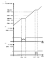
図5、図6に、図4で説明した材質1と材質2でプロセススピード(画像形成時のシートPの搬送速度でもある)が同じ場合のタイミングチャートを示す。ここで、両面印刷時の待機位置、待機時間は材質1と材質2とでは変更されるが、両面印刷時の再給紙タイミングは材質1でも材質2でも同じタイミングとし、両面印刷全体の生産性は低下させないように制御する。図5にシートPが材質1の場合の両面印刷時の待機制御を示し、図6にシートPが材質2の場合の両面印刷時の待機制御を示す。
5 and 6 are timing charts in the case where the process speed (which is also the conveyance speed of the sheet P during image formation) is the same for the
(材質1の場合)
図5(a)は縦軸にシートPの先端の位置を示し、図5(b)は縦軸に両面モータ204の速度(モータ速度)を示し、図5(c)は両面モータ205の速度(モータ速度)を示す。いずれも横軸は時間tを示す。シートPが普通紙のような材質1の場合、両面搬送パス85にシートPが搬送されて、シートPの先端が待機位置2に到達するまでの間、シートPは両面ローラ86〜89により搬送される。図5(b)、図5(c)に示すように、両面ローラ86、87を駆動する両面モータ204は一定の速度ν1=340mm/sで動作し、両面ローラ88、89を駆動する両面モータ205も同じ一定の速度ν1=340mm/sで動作する。両面モータ204、205の一定の速度ν1=340mm/sがプロセススピードである。
(In the case of material 1)
5A shows the position of the leading edge of the sheet P on the vertical axis, FIG. 5B shows the speed (motor speed) of the double-
このように、シートPが材質1である場合、シートPは待機位置1では搬送を停止されず、待機位置1での待機時間T1は、T1=0msとなる。シートPの先端が待機位置2、即ち搬送センサ102から20mm下流側の位置に到達したとき、図4(a)のS104で説明したように両面モータ205の動作が停止し、シートPの搬送が停止される。その後、両面モータ205が停止してから待機時間T2(例えば、T2=500ms)が経過した再給紙タイミングである図4(a)のS105のタイミングで、再び両面モータ205がν1=340mm/sの速度で駆動を開始し、シートPが再給紙される。即ち、シートPが材質1である場合、水蒸気が放出される期間において、シートPが同一箇所にとどまっている時間が0或いは非常に短い時間であるため、結露の発生が抑制される。
Thus, when the sheet P is the
(材質2の場合)
図6(a)〜図6(c)のグラフの横軸、縦軸は、図5(a)〜図5(c)と対応しており、説明を省略する。シートPがコート紙のような材質2の場合、両面搬送パス85にシートPが搬送されて、シートPの先端が待機位置1に到達するまでの間、シートPは両面ローラ86、87により搬送される。図6(b)に示すように、両面ローラ86、87を駆動する両面モータ204は一定の速度ν1=340mm/sで動作する。シートPの先端が、待機位置1、即ち搬送センサ101から20mm下流側の位置に到達したとき、図4(b)のS204のタイミングで両面モータ204の動作が停止される。これにより、両面ローラ86、87の駆動が停止され、シートPの搬送が停止する。その後、両面モータ204が停止してから待機時間T3=300msが経過した図4(b)のS205のタイミングで、再び両面モータ205がν1=340mm/sの速度で駆動を開始し、シートPの搬送が再開される。
(In the case of material 2)
The horizontal and vertical axes of the graphs in FIGS. 6A to 6C correspond to FIGS. 5A to 5C, and the description thereof is omitted. When the sheet P is made of a
シートPの搬送が再開されて待機位置2に到達するまでの間、シートPは両面ローラ88、89により搬送される。図6(c)に示すように、両面ローラ88、89を駆動する両面モータ205は一定の速度ν1=340mm/sで動作する。シートPの先端が、待機位置2、即ち搬送センサ102から20mm下流側の位置に到達したとき、図4(b)のS207のタイミングで両面モータ205の動作が停止される。これにより、両面ローラ88、89の駆動が停止され、シートPの搬送が停止する。その後、両面モータ205が停止してから待機時間T4=200msが経過した再給紙タイミングである図4(b)のS208のタイミングで、再び両面モータ205がν1=340mm/sの速度で駆動を開始し、シートPが再給紙される。即ち、シートPが材質2である場合、水蒸気が放出される期間において、シートPが同一箇所にとどまっている時間が分散されるため、結露の発生が抑制される。
The sheet P is conveyed by the double-
ここで、材質1の場合の待機位置1での待機時間T1(0ms)と、材質2の場合の待機位置1での待機時間T3(300ms)の関係は、T1<T3となる。即ち、より透気度の大きい、例えばコート紙等の材質2では、定着部5の下流側であって、より定着部5に近い待機位置1で材質1よりも長い時間シートPを待機させることにより、結露を防止することができる。また、材質2では、待機位置1における待機時間T3と待機位置2における待機時間T4との間に、T3>T4という関係が成り立つように待機時間を設定する。即ち、シートPが材質2の場合には、定着部5の下流側であって、定着部5に近い待機位置1よりも、結露が発生し易い定着部5から遠い待機位置2での待機時間を短くすることによって、結露の発生を防止することができる。
Here, the relationship between the standby time T 1 (0 ms) at the
また、材質1の場合の待機位置2での待機時間T2(500ms)と、材質2の場合の待機位置2での待機時間T4(200ms)の関係は、T2>T4となる。即ち、より透気度の小さい、例えば普通紙等の材質1では、定着部5の下流側であって、定着部5から遠い待機位置2でシートPを待機させることにより、結露の発生を防止することができる。
In addition, the relationship between the standby time T 2 (500 ms) at the
更に、材質1と材質2でプロセススピードを同じにした場合、材質1における待機時間の総和(T1+T2=0ms+500ms=500ms)と、材質2における待機時間の総和(T3+T4=300ms+200ms=500ms)は、等しい。即ち、材質1と材質2でプロセススピードが同じである場合、待機時間の総和はシートPの材質によらず一定となる。なお、この待機時間の総和には、モータの停止や起動に要する時間が含まれている。従って、実際にシートが各待機位置に停止している時間の総和は停止回数の多い材質2のシートの方がわずかに短い。これにより、シートPを両面搬送パス85からレジストレーションローラ対76へ再給紙するタイミングは材質によらず同じタイミングとなる。即ち、シートが定着器を通過してから待機位置2から再搬送されるまでの時間はシートの材質によらず同じである。これにより、材質によって印刷動作全体の生産性が低下することはない。
Further, when the process speed is the same for
なお、本実施の形態では、材質1と材質2でプロセススピードが一定(例えば340mm/s)の場合について説明した。一方、シートPの材質によってプロセススピードが異なる場合には、各プロセススピードに応じた再給紙タイミングとなるように、待機位置1及び待機位置2での待機時間が設定されることとなる。
In the present embodiment, the case where the process speed is constant (for example, 340 mm / s) using the
以上、本実施の形態によれば、生産性を低下させずに低コストで画像形成装置内の結露の発生を低減させることができる。 As described above, according to the present embodiment, it is possible to reduce the occurrence of condensation in the image forming apparatus at low cost without reducing productivity.
5 定着部
50 コントローラ
85 両面搬送パス
P シート
5 Fixing
Claims (15)
シートに未定着のトナー像を形成する画像形成手段と、
前記画像形成手段により形成されたトナー像をシートに定着させる定着手段と、
前記定着手段によりシートの第一面のトナー像が定着された後のシートの第二面に画像形成を行うためにシートが搬送される両面搬送路と、
前記シートの搬送を制御する制御手段と、
を備え、
前記制御手段は、前記両面搬送路において、前記定着手段よりもシートの搬送方向における下流側の第一の待機位置と前記第一の待機位置よりも下流側の第二の待機位置との何れでもシートを停止可能とし、前記第一の待機位置でシートを停止させる第一停止時間と前記第二の待機位置でシートを停止させる第二停止時間を、透気度が異なるシートの材質に応じて変更することを特徴とする画像形成装置。 An image forming apparatus for forming an image on a second surface different from the first surface of the sheet and the first surface,
Image forming means for forming an unfixed toner image on the sheet;
Fixing means for fixing the toner image formed by the image forming means to a sheet;
A double-sided conveyance path through which the sheet is conveyed in order to form an image on the second side of the sheet after the toner image on the first side of the sheet is fixed by the fixing unit;
Control means for controlling conveyance of the sheet;
With
In the double-sided conveyance path, the control unit may be any one of a first standby position downstream of the fixing unit in the sheet conveyance direction and a second standby position downstream of the first standby position. The first stop time for stopping the sheet at the first standby position and the second stop time for stopping the sheet at the second standby position according to the material of the sheet having different air permeability. An image forming apparatus that is changed.
前記制御手段は、前記第一の検知手段の検知結果に基づいて、シートが前記第一の待機位置に到達したことを判断することを特徴とする請求項1又は2に記載の画像形成装置。 Provided on the downstream side in the transport direction with respect to the fixing unit, the first detection unit for detecting the sheet,
Said control means based on a detection result of the first detecting means, the sheet image forming apparatus according to claim 1 or 2, characterized in that to determine that it has reached the first standby position .
前記制御手段は、前記第一の検知手段の検知結果に基づきシートが前記第一の待機位置に到達したと判断した場合、前記第一の搬送手段の動作を停止させてシートを停止させることを特徴とする請求項3に記載の画像形成装置。 A first conveying unit provided between the fixing unit and the first detecting unit for conveying a sheet;
When the control unit determines that the sheet has reached the first standby position based on the detection result of the first detection unit, the control unit stops the operation by stopping the operation of the first conveyance unit. The image forming apparatus according to claim 3.
前記制御手段は、前記第二の検知手段の検知結果に基づいて、シートが前記第二の待機位置に到達したことを判断することを特徴とする請求項3乃至5のいずれか1項に記載の画像形成装置。 Provided on the downstream side of the first detection means, comprising a second detection means for detecting the sheet,
6. The control unit according to claim 3, wherein the control unit determines that the sheet has reached the second standby position based on a detection result of the second detection unit. Image forming apparatus.
前記制御手段は、前記第二の検知手段の検知結果に基づきシートが前記第二の待機位置に到達したと判断した場合、前記第二の搬送手段の動作を停止させてシートを待機させることを特徴とする請求項6に記載の画像形成装置。 Provided between the first detection means and the second detection means, comprising a second conveying means for conveying a sheet;
When the control unit determines that the sheet has reached the second standby position based on the detection result of the second detection unit, the control unit stops the operation of the second conveyance unit and waits for the sheet. The image forming apparatus according to claim 6.
シートに未定着のトナー像を形成する画像形成手段と、
前記画像形成手段により形成されたトナー像をシートに定着させる定着手段と、
前記定着手段によりシートの第一面のトナー像が定着された後のシートの第二面に画像形成を行うためにシートが搬送される両面搬送路と、
前記両面搬送路を搬送されるシートを前記両面搬送路の第一の待機位置とシートの搬送方向において前記第一の待機位置よりも下流側の第二の待機位置との何れでも停止可能とするようシートの搬送を制御する制御手段と、
を備え、
前記制御手段は、第一の材質のシートが前記両面搬送路を搬送される場合、前記第一の材質のシートを前記第一の待機位置で停止させることなく前記第二の待機位置に停止させ、前記第一の材質のシートの透気度よりも高い透気度を有する第二の材質のシートが前記両面搬送路を搬送される場合、前記第二の材質のシートを前記第一の待機位置と前記第二の待機位置の両方に停止させることを特徴とする画像形成装置。 An image forming apparatus for forming an image on a second surface different from the first surface of the sheet and the first surface,
Image forming means for forming an unfixed toner image on the sheet;
Fixing means for fixing the toner image formed by the image forming means to a sheet;
A double-sided conveyance path through which the sheet is conveyed in order to form an image on the second side of the sheet after the toner image on the first side of the sheet is fixed by the fixing unit;
The sheet conveyed through the duplex conveyance path can be stopped at either the first standby position of the duplex conveyance path or the second standby position downstream of the first standby position in the sheet conveyance direction. Control means for controlling the conveyance of the sheet,
With
When the first material sheet is conveyed on the double-sided conveyance path, the control unit stops the first material sheet at the second standby position without stopping at the first standby position. When a second material sheet having a higher air permeability than that of the first material sheet is conveyed in the double-sided conveyance path, the second material sheet is moved to the first standby state. An image forming apparatus that stops at both the position and the second standby position.
Priority Applications (2)
| Application Number | Priority Date | Filing Date | Title |
|---|---|---|---|
| JP2014107211A JP6362086B2 (en) | 2014-05-23 | 2014-05-23 | Image forming apparatus |
| US14/717,257 US9507307B2 (en) | 2014-05-23 | 2015-05-20 | Image forming apparatus |
Applications Claiming Priority (1)
| Application Number | Priority Date | Filing Date | Title |
|---|---|---|---|
| JP2014107211A JP6362086B2 (en) | 2014-05-23 | 2014-05-23 | Image forming apparatus |
Publications (3)
| Publication Number | Publication Date |
|---|---|
| JP2015222367A JP2015222367A (en) | 2015-12-10 |
| JP2015222367A5 JP2015222367A5 (en) | 2017-07-06 |
| JP6362086B2 true JP6362086B2 (en) | 2018-07-25 |
Family
ID=54556010
Family Applications (1)
| Application Number | Title | Priority Date | Filing Date |
|---|---|---|---|
| JP2014107211A Active JP6362086B2 (en) | 2014-05-23 | 2014-05-23 | Image forming apparatus |
Country Status (2)
| Country | Link |
|---|---|
| US (1) | US9507307B2 (en) |
| JP (1) | JP6362086B2 (en) |
Families Citing this family (8)
| Publication number | Priority date | Publication date | Assignee | Title |
|---|---|---|---|---|
| JP6591305B2 (en) * | 2016-02-10 | 2019-10-16 | 株式会社沖データ | Image forming apparatus |
| JP2017151165A (en) * | 2016-02-22 | 2017-08-31 | コニカミノルタ株式会社 | Image forming device and control program |
| JP2019008217A (en) * | 2017-06-27 | 2019-01-17 | コニカミノルタ株式会社 | Image formation device, image formation system, image formation method, and image formation device-purpose program |
| JP6984520B2 (en) * | 2018-03-28 | 2021-12-22 | 沖電気工業株式会社 | Sheet-shaped medium transfer device, image forming device and sheet-like medium transfer method |
| JP7322416B2 (en) * | 2019-02-04 | 2023-08-08 | ブラザー工業株式会社 | image forming device |
| JP2021134033A (en) * | 2020-02-26 | 2021-09-13 | 京セラドキュメントソリューションズ株式会社 | Original feeder |
| JP2023031850A (en) * | 2021-08-25 | 2023-03-09 | 富士フイルムビジネスイノベーション株式会社 | Detection device, and image formation device |
| JP2023031849A (en) * | 2021-08-25 | 2023-03-09 | 富士フイルムビジネスイノベーション株式会社 | Detection device, and image formation device |
Family Cites Families (7)
| Publication number | Priority date | Publication date | Assignee | Title |
|---|---|---|---|---|
| US5987300A (en) * | 1997-04-10 | 1999-11-16 | Ricoh Company, Ltd. | Image forming apparatus printing on both sides of a printing medium |
| JP2001206644A (en) * | 2000-01-21 | 2001-07-31 | Canon Inc | Re-feeding device and image forming device |
| JP5164526B2 (en) * | 2007-11-01 | 2013-03-21 | キヤノン株式会社 | Image forming apparatus |
| JP5506331B2 (en) * | 2009-10-30 | 2014-05-28 | キヤノン株式会社 | Image forming apparatus |
| JP2011191544A (en) * | 2010-03-15 | 2011-09-29 | Ricoh Co Ltd | Image-forming device |
| US8720886B2 (en) * | 2010-10-13 | 2014-05-13 | Canon Kabushiki Kaisha | Sheet conveying apparatus and image forming apparatus |
| JP5216129B2 (en) * | 2011-09-06 | 2013-06-19 | キヤノン株式会社 | Image forming apparatus |
-
2014
- 2014-05-23 JP JP2014107211A patent/JP6362086B2/en active Active
-
2015
- 2015-05-20 US US14/717,257 patent/US9507307B2/en active Active
Also Published As
| Publication number | Publication date |
|---|---|
| US20150338808A1 (en) | 2015-11-26 |
| US9507307B2 (en) | 2016-11-29 |
| JP2015222367A (en) | 2015-12-10 |
Similar Documents
| Publication | Publication Date | Title |
|---|---|---|
| JP6362086B2 (en) | Image forming apparatus | |
| JP5924857B2 (en) | Image forming apparatus | |
| JP6272134B2 (en) | Fixing device | |
| US9588467B2 (en) | Image forming apparatus | |
| JP2010262040A (en) | Image forming apparatus | |
| JP5482163B2 (en) | Curl correction device and image forming apparatus having the same | |
| JP4926526B2 (en) | Image forming apparatus and control method thereof | |
| JP6624840B2 (en) | Image forming device | |
| JP5581854B2 (en) | Fixing apparatus and image forming apparatus | |
| JP2013160964A (en) | Image forming apparatus | |
| JP2017207648A (en) | Image forming apparatus | |
| JP2005181538A (en) | Image forming apparatus | |
| JP2015108799A (en) | Fixing device, and image forming apparatus | |
| JP6776557B2 (en) | Image forming device | |
| JP2007063001A (en) | Image forming device | |
| JP2015148786A (en) | image forming apparatus | |
| JP2012042826A (en) | Fixing device and image forming apparatus | |
| JP2010117470A (en) | Image forming apparatus | |
| JP6840983B2 (en) | Fixing device, image forming device, and control method of image forming device | |
| JP2006273470A (en) | Curl correcting device and image forming apparatus | |
| JP5744533B2 (en) | Image forming apparatus | |
| US20180011439A1 (en) | Image forming apparatus | |
| JP2016128886A (en) | Image forming apparatus | |
| JP2005316184A (en) | Image forming apparatus | |
| JP2012128246A (en) | Image-forming device |
Legal Events
| Date | Code | Title | Description |
|---|---|---|---|
| RD03 | Notification of appointment of power of attorney |
Free format text: JAPANESE INTERMEDIATE CODE: A7423 Effective date: 20160215 |
|
| RD04 | Notification of resignation of power of attorney |
Free format text: JAPANESE INTERMEDIATE CODE: A7424 Effective date: 20160215 |
|
| A521 | Request for written amendment filed |
Free format text: JAPANESE INTERMEDIATE CODE: A523 Effective date: 20170522 |
|
| A621 | Written request for application examination |
Free format text: JAPANESE INTERMEDIATE CODE: A621 Effective date: 20170522 |
|
| RD04 | Notification of resignation of power of attorney |
Free format text: JAPANESE INTERMEDIATE CODE: A7424 Effective date: 20171201 |
|
| A131 | Notification of reasons for refusal |
Free format text: JAPANESE INTERMEDIATE CODE: A131 Effective date: 20180227 |
|
| A977 | Report on retrieval |
Free format text: JAPANESE INTERMEDIATE CODE: A971007 Effective date: 20180228 |
|
| A521 | Request for written amendment filed |
Free format text: JAPANESE INTERMEDIATE CODE: A523 Effective date: 20180426 |
|
| TRDD | Decision of grant or rejection written | ||
| A01 | Written decision to grant a patent or to grant a registration (utility model) |
Free format text: JAPANESE INTERMEDIATE CODE: A01 Effective date: 20180522 |
|
| A61 | First payment of annual fees (during grant procedure) |
Free format text: JAPANESE INTERMEDIATE CODE: A61 Effective date: 20180619 |
|
| R151 | Written notification of patent or utility model registration |
Ref document number: 6362086 Country of ref document: JP Free format text: JAPANESE INTERMEDIATE CODE: R151 |