JP6361769B1 - Position prediction apparatus and position detection apparatus - Google Patents
Position prediction apparatus and position detection apparatus Download PDFInfo
- Publication number
- JP6361769B1 JP6361769B1 JP2017062065A JP2017062065A JP6361769B1 JP 6361769 B1 JP6361769 B1 JP 6361769B1 JP 2017062065 A JP2017062065 A JP 2017062065A JP 2017062065 A JP2017062065 A JP 2017062065A JP 6361769 B1 JP6361769 B1 JP 6361769B1
- Authority
- JP
- Japan
- Prior art keywords
- unit
- rotation angle
- time
- estimated
- operating body
- Prior art date
- Legal status (The legal status is an assumption and is not a legal conclusion. Google has not performed a legal analysis and makes no representation as to the accuracy of the status listed.)
- Active
Links
- 238000001514 detection method Methods 0.000 title claims description 108
- 230000005291 magnetic effect Effects 0.000 claims description 85
- 238000012545 processing Methods 0.000 claims description 48
- 230000001133 acceleration Effects 0.000 claims description 25
- 238000004088 simulation Methods 0.000 claims description 25
- 230000000694 effects Effects 0.000 claims description 2
- 238000005070 sampling Methods 0.000 description 73
- 230000005415 magnetization Effects 0.000 description 36
- 230000000052 comparative effect Effects 0.000 description 14
- 238000000034 method Methods 0.000 description 13
- 238000013213 extrapolation Methods 0.000 description 11
- 230000008569 process Effects 0.000 description 9
- 238000004364 calculation method Methods 0.000 description 8
- 238000006243 chemical reaction Methods 0.000 description 6
- 230000005290 antiferromagnetic effect Effects 0.000 description 5
- 238000010586 diagram Methods 0.000 description 4
- 238000001914 filtration Methods 0.000 description 4
- 230000008859 change Effects 0.000 description 3
- 230000007423 decrease Effects 0.000 description 2
- 230000005293 ferrimagnetic effect Effects 0.000 description 2
- 230000005294 ferromagnetic effect Effects 0.000 description 2
- 238000005259 measurement Methods 0.000 description 2
- 238000012935 Averaging Methods 0.000 description 1
- 230000003321 amplification Effects 0.000 description 1
- 239000002885 antiferromagnetic material Substances 0.000 description 1
- 230000004888 barrier function Effects 0.000 description 1
- 230000008901 benefit Effects 0.000 description 1
- 230000008878 coupling Effects 0.000 description 1
- 238000010168 coupling process Methods 0.000 description 1
- 238000005859 coupling reaction Methods 0.000 description 1
- 238000013461 design Methods 0.000 description 1
- 230000005389 magnetism Effects 0.000 description 1
- 238000003199 nucleic acid amplification method Methods 0.000 description 1
- 230000004044 response Effects 0.000 description 1
- 239000004065 semiconductor Substances 0.000 description 1
- 239000007787 solid Substances 0.000 description 1
- 239000000758 substrate Substances 0.000 description 1
Images

Classifications
-
- G—PHYSICS
- G01—MEASURING; TESTING
- G01B—MEASURING LENGTH, THICKNESS OR SIMILAR LINEAR DIMENSIONS; MEASURING ANGLES; MEASURING AREAS; MEASURING IRREGULARITIES OF SURFACES OR CONTOURS
- G01B7/00—Measuring arrangements characterised by the use of electric or magnetic techniques
- G01B7/003—Measuring arrangements characterised by the use of electric or magnetic techniques for measuring position, not involving coordinate determination
-
- G—PHYSICS
- G01—MEASURING; TESTING
- G01D—MEASURING NOT SPECIALLY ADAPTED FOR A SPECIFIC VARIABLE; ARRANGEMENTS FOR MEASURING TWO OR MORE VARIABLES NOT COVERED IN A SINGLE OTHER SUBCLASS; TARIFF METERING APPARATUS; MEASURING OR TESTING NOT OTHERWISE PROVIDED FOR
- G01D5/00—Mechanical means for transferring the output of a sensing member; Means for converting the output of a sensing member to another variable where the form or nature of the sensing member does not constrain the means for converting; Transducers not specially adapted for a specific variable
- G01D5/12—Mechanical means for transferring the output of a sensing member; Means for converting the output of a sensing member to another variable where the form or nature of the sensing member does not constrain the means for converting; Transducers not specially adapted for a specific variable using electric or magnetic means
- G01D5/14—Mechanical means for transferring the output of a sensing member; Means for converting the output of a sensing member to another variable where the form or nature of the sensing member does not constrain the means for converting; Transducers not specially adapted for a specific variable using electric or magnetic means influencing the magnitude of a current or voltage
- G01D5/16—Mechanical means for transferring the output of a sensing member; Means for converting the output of a sensing member to another variable where the form or nature of the sensing member does not constrain the means for converting; Transducers not specially adapted for a specific variable using electric or magnetic means influencing the magnitude of a current or voltage by varying resistance
-
- G—PHYSICS
- G01—MEASURING; TESTING
- G01B—MEASURING LENGTH, THICKNESS OR SIMILAR LINEAR DIMENSIONS; MEASURING ANGLES; MEASURING AREAS; MEASURING IRREGULARITIES OF SURFACES OR CONTOURS
- G01B7/00—Measuring arrangements characterised by the use of electric or magnetic techniques
- G01B7/30—Measuring arrangements characterised by the use of electric or magnetic techniques for measuring angles or tapers; for testing the alignment of axes
-
- G—PHYSICS
- G01—MEASURING; TESTING
- G01D—MEASURING NOT SPECIALLY ADAPTED FOR A SPECIFIC VARIABLE; ARRANGEMENTS FOR MEASURING TWO OR MORE VARIABLES NOT COVERED IN A SINGLE OTHER SUBCLASS; TARIFF METERING APPARATUS; MEASURING OR TESTING NOT OTHERWISE PROVIDED FOR
- G01D5/00—Mechanical means for transferring the output of a sensing member; Means for converting the output of a sensing member to another variable where the form or nature of the sensing member does not constrain the means for converting; Transducers not specially adapted for a specific variable
- G01D5/12—Mechanical means for transferring the output of a sensing member; Means for converting the output of a sensing member to another variable where the form or nature of the sensing member does not constrain the means for converting; Transducers not specially adapted for a specific variable using electric or magnetic means
- G01D5/14—Mechanical means for transferring the output of a sensing member; Means for converting the output of a sensing member to another variable where the form or nature of the sensing member does not constrain the means for converting; Transducers not specially adapted for a specific variable using electric or magnetic means influencing the magnitude of a current or voltage
- G01D5/142—Mechanical means for transferring the output of a sensing member; Means for converting the output of a sensing member to another variable where the form or nature of the sensing member does not constrain the means for converting; Transducers not specially adapted for a specific variable using electric or magnetic means influencing the magnitude of a current or voltage using Hall-effect devices
- G01D5/145—Mechanical means for transferring the output of a sensing member; Means for converting the output of a sensing member to another variable where the form or nature of the sensing member does not constrain the means for converting; Transducers not specially adapted for a specific variable using electric or magnetic means influencing the magnitude of a current or voltage using Hall-effect devices influenced by the relative movement between the Hall device and magnetic fields
-
- G—PHYSICS
- G01—MEASURING; TESTING
- G01P—MEASURING LINEAR OR ANGULAR SPEED, ACCELERATION, DECELERATION, OR SHOCK; INDICATING PRESENCE, ABSENCE, OR DIRECTION, OF MOVEMENT
- G01P3/00—Measuring linear or angular speed; Measuring differences of linear or angular speeds
- G01P3/42—Devices characterised by the use of electric or magnetic means
- G01P3/44—Devices characterised by the use of electric or magnetic means for measuring angular speed
- G01P3/48—Devices characterised by the use of electric or magnetic means for measuring angular speed by measuring frequency of generated current or voltage
- G01P3/481—Devices characterised by the use of electric or magnetic means for measuring angular speed by measuring frequency of generated current or voltage of pulse signals
- G01P3/487—Devices characterised by the use of electric or magnetic means for measuring angular speed by measuring frequency of generated current or voltage of pulse signals delivered by rotating magnets
-
- G—PHYSICS
- G01—MEASURING; TESTING
- G01D—MEASURING NOT SPECIALLY ADAPTED FOR A SPECIFIC VARIABLE; ARRANGEMENTS FOR MEASURING TWO OR MORE VARIABLES NOT COVERED IN A SINGLE OTHER SUBCLASS; TARIFF METERING APPARATUS; MEASURING OR TESTING NOT OTHERWISE PROVIDED FOR
- G01D5/00—Mechanical means for transferring the output of a sensing member; Means for converting the output of a sensing member to another variable where the form or nature of the sensing member does not constrain the means for converting; Transducers not specially adapted for a specific variable
- G01D5/12—Mechanical means for transferring the output of a sensing member; Means for converting the output of a sensing member to another variable where the form or nature of the sensing member does not constrain the means for converting; Transducers not specially adapted for a specific variable using electric or magnetic means
- G01D5/244—Mechanical means for transferring the output of a sensing member; Means for converting the output of a sensing member to another variable where the form or nature of the sensing member does not constrain the means for converting; Transducers not specially adapted for a specific variable using electric or magnetic means influencing characteristics of pulses or pulse trains; generating pulses or pulse trains
- G01D5/24471—Error correction
- G01D5/24495—Error correction using previous values
Landscapes
- Physics & Mathematics (AREA)
- General Physics & Mathematics (AREA)
- Transmission And Conversion Of Sensor Element Output (AREA)
- Measurement Of Length, Angles, Or The Like Using Electric Or Magnetic Means (AREA)
Abstract
【課題】連続的に作動する動作体の所定時刻における位置を極めて高い精度で予測することのできる位置予測装置及び当該位置予測装置を含む位置検出装置を提供する。
【解決手段】連続的に作動する動作体の所定時刻における位置を予測する位置予測装置は、所定時刻よりも過去の位置推定時刻における動作体の推定位置状態を求める推定部と、推定部により推定された動作体の推定位置状態に基づき、動作体の所定時刻における位置を予測する位置予測部とを備える。
【選択図】図1A position predicting device capable of predicting a position of an operating body that operates continuously at a predetermined time with extremely high accuracy and a position detecting device including the position predicting device are provided.
A position prediction apparatus for predicting a position of a moving body that operates continuously at a predetermined time includes an estimation unit that obtains an estimated position state of the moving body at a position estimation time that is earlier than the predetermined time, and an estimation unit that estimates the position. And a position predicting unit that predicts the position of the moving object at a predetermined time based on the estimated position state of the moving object.
[Selection] Figure 1
Description
本発明は、動作体の作動による位置を予測する装置及び当該動作体の作動による位置を検出する装置に関する。 The present invention relates to an apparatus for predicting a position due to operation of an operating body and an apparatus for detecting a position due to operation of the operating body.
従来、工作機械等における機械可動部に取り付けられるサーボモータ等の動作体の回転動作等による物理量の変化を検出することで、当該動作体の位置を検出する位置検出装置が用いられている。この位置検出装置による出力を通じて動作体の回転動作等を連続的に追尾し、動作体にフィードバックすることで、当該動作体の動作制御が行われる。 2. Description of the Related Art Conventionally, a position detecting device that detects the position of an operating body by detecting a change in a physical quantity caused by a rotating operation of an operating body such as a servo motor attached to a machine moving part in a machine tool or the like has been used. By continuously tracking the rotational motion of the operating body through the output from the position detecting device and feeding back to the operating body, the motion control of the operating body is performed.
このような位置検出装置としては、磁界を発生する磁界発生部と磁気検出装置とを備えるものが知られている。かかる磁気検出装置は、一般に、磁界発生部により発生する外部磁界を検知し、磁界発生部が相対的に移動した物理量を示すアナログ信号を出力する磁気検出素子と、上記アナログ信号をデジタル信号に変換し、当該デジタル信号に基づいて現在時刻における動作体の位置を算出することのできる演算回路とを備え、磁気検出素子と演算回路とが同一の半導体チップ上に集積されて一体化された集積回路として構成される。 As such a position detection device, a device including a magnetic field generation unit that generates a magnetic field and a magnetic detection device is known. In general, such a magnetic detection device detects an external magnetic field generated by a magnetic field generation unit and outputs an analog signal indicating a physical quantity to which the magnetic field generation unit has relatively moved, and converts the analog signal into a digital signal. And an arithmetic circuit capable of calculating the position of the operating body at the current time based on the digital signal, and an integrated circuit in which the magnetic detection element and the arithmetic circuit are integrated on the same semiconductor chip. Configured as
このような磁気検出装置の演算回路において算出された、現在時刻における動作体の位置情報に基づき、動作体の動作制御が行われる。しかし、磁気検出素子から出力されるアナログ信号についてのフィルタリング処理、アナログ信号をデジタル信号に変換する処理、当該デジタル信号に含まれるノイズを除去するフィルタリング処理、当該デジタル信号に基づいて現在時刻における動作体の位置を算出する処理等により、遅延が生じ得る。そのため、特に高速に作動する動作体を精確に動作制御するために、上記遅延を取り戻すべく、動作体の位置情報から未来の時刻における動作体の位置を予測し、当該予測値に基づいて動作体を制御する方法が採用されている。 Based on the position information of the operating body at the current time calculated by the arithmetic circuit of such a magnetic detection device, motion control of the operating body is performed. However, a filtering process for an analog signal output from the magnetic detection element, a process for converting the analog signal into a digital signal, a filtering process for removing noise contained in the digital signal, and an operating body at the current time based on the digital signal There may be a delay due to the process of calculating the position of. Therefore, in order to accurately control an operating body that operates particularly at high speed, in order to recover the delay, the position of the operating body at a future time is predicted from the position information of the operating body, and the operating body is based on the predicted value. The method of controlling is adopted.
このような方法を実施可能な位置検出装置として、従来、回転体に設けられた磁石の磁界強度を計測する磁気センサ素子、磁気センサ素子の計測値から磁石の回転角度を演算する角度計算手段、角度計算手段の出力する回転角度のデータを記憶しておく記憶手段、記憶手段の記憶内容を統計処理することにより回転状態を推定する回転状態推定手段、回転状態推定手段で推定された回転状態から以降の回転角度を予測する外挿処理手段、及び外挿処理手段で予測した回転角度に基づいて回転角度を算出し出力する出力手段を備える回転検出装置が提案されている(特許文献1参照)。 Conventionally, as a position detection device capable of performing such a method, a magnetic sensor element that measures the magnetic field strength of a magnet provided on a rotating body, an angle calculation means that calculates the rotation angle of the magnet from the measurement value of the magnetic sensor element, Storage means for storing rotation angle data output by the angle calculation means, rotation state estimation means for estimating the rotation state by statistically processing the stored contents of the storage means, and the rotation state estimated by the rotation state estimation means A rotation detection device including an extrapolation processing unit that predicts a subsequent rotation angle and an output unit that calculates and outputs the rotation angle based on the rotation angle predicted by the extrapolation processing unit has been proposed (see Patent Document 1). .
上記特許文献1に記載の回転検出装置において、磁気センサ素子により一定サンプリング周期で現在時刻の角度が出力され、記憶手段に記憶、蓄積される。そして、記憶手段に記憶、蓄積されている現在時刻の角度データに至る過去の角度データに、平均化フィルタ等の処理を行い、予測すべきサンプリング時刻における角度(予測角度)が求められる。
In the rotation detection device described in
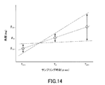
磁気センサ素子により一定サンプリング周期で出力される、現在時刻の角度データには所定のノイズが含まれる。このようなノイズを含む角度データを用いて、上記特許文献1のように線形外挿処理により予測角度を求めると、予測角度の精度が低下してしまうという問題がある。図14に示す予測モデルから明らかなように、所定のサンプリング時刻TXの角度θXとそれよりも過去のサンプリング時刻TX-1の角度θX-1とが、それぞれ所定のノイズ(図14中、矢印はノイズ幅を表す。)を含み、それらの角度データを用いて所定の時刻TXよりも未来のサンプリング時刻TX+1における予測角度θX+1を線形外挿予測する場合、予測角度θX+1に含まれるノイズは角度θX,θX-1に含まれるノイズよりも増幅されてしまう。
The angle data at the current time that is output by the magnetic sensor element at a constant sampling cycle includes predetermined noise. When the angle data including such noise is used to obtain the predicted angle by linear extrapolation processing as in
また、上記角度データを用いた平均フィルタ処理等により予測角度を求めようとすると、それによる群遅延が生じてしまい、予測すべきサンプリング時刻をさらに未来に設定する必要がある。予測すべきサンプリング時刻をさらに未来に設定すると、ノイズの増幅を抑制することができず、予測角度の精度が低下してしまうという問題がある。 In addition, if an attempt is made to obtain a predicted angle by means of an average filter process using the angle data, a group delay is caused thereby, and it is necessary to further set the sampling time to be predicted in the future. If the sampling time to be predicted is further set in the future, there is a problem that noise amplification cannot be suppressed and the accuracy of the prediction angle is lowered.
予測角度の精度を高めるために、磁気センサ素子により出力される角度データについてフィルタ回路等による処理を行い、当該角度データに含まれるノイズを低減することが考えられる。フィルタ回路等による処理によって、角度データに含まれるノイズを低減することは可能である。しかし、フィルタ回路等による処理により、さらなる遅延が生じてしまうため、予測すべきサンプリング時刻をさらに未来に設定せざるを得ない。このように予測すべきサンプリング時刻をさらに未来に設定すると、フィルタ回路等により低減されたノイズが再び増幅して予測角度に含まれてしまうため、結果として予測角度の精度が低下してしまうという問題がある。 In order to increase the accuracy of the predicted angle, it is conceivable that the angle data output from the magnetic sensor element is processed by a filter circuit or the like to reduce noise included in the angle data. It is possible to reduce noise included in the angle data by processing using a filter circuit or the like. However, since further delay occurs due to processing by the filter circuit or the like, the sampling time to be predicted has to be set in the future. If the sampling time to be predicted is set in the future in this way, the noise reduced by the filter circuit or the like is amplified again and included in the prediction angle, resulting in a decrease in accuracy of the prediction angle as a result. There is.
上記課題に鑑み、本発明は、連続的に作動する動作体の所定時刻における位置を極めて高い精度で予測することのできる位置予測装置及び当該位置予測装置を含む位置検出装置を提供することを目的とする。 In view of the above problems, an object of the present invention is to provide a position prediction device capable of predicting the position of a continuously operating operating body at a predetermined time with extremely high accuracy, and a position detection device including the position prediction device. And
上記課題を解決するために、本発明は、連続的に作動する動作体の所定時刻における位置を予測する装置であって、前記所定時刻よりも過去の第1時刻における前記動作体の推定位置状態を求める推定部と、前記推定部により推定された前記動作体の推定位置状態に基づき、前記動作体の前記所定時刻における位置を予測する位置予測部と、前記動作体に設けられている磁界発生部の外部磁界を検出することで出力される前記動作体の位置に関する信号に基づき、前記動作体の位置状態を算出する演算処理部と、前記推定部により推定された、前記第1時刻よりも過去の第2時刻における前記動作体の推定位置状態に基づいて、前記動作体の前記第1時刻におけるシミュレート位置状態を求めるシミュレート部とを備え、前記推定部は、前記シミュレート部により求められた前記第1時刻における前記動作体の前記シミュレート位置状態と、前記演算処理部により算出された前記第1時刻における前記動作体の前記位置状態とに基づいて、前記動作体の前記第1時刻における前記推定位置状態を求めることを特徴とする位置予測装置を提供する。 In order to solve the above problems, the present invention is an apparatus for predicting a position of a continuously operating operating body at a predetermined time, and an estimated position state of the operating body at a first time before the predetermined time. An estimation unit for obtaining the position, a position prediction unit for predicting the position of the operating body at the predetermined time based on the estimated position state of the operating body estimated by the estimating unit, and a magnetic field generation provided in the operating body An arithmetic processing unit that calculates a position state of the operating body based on a signal related to the position of the operating body that is output by detecting an external magnetic field of the unit, and the first time estimated by the estimating unit based on the estimated positional state of the operation member in a past second time, and a simulation unit for determining the simulated position state in the first time of the operation member, wherein the estimation unit, wherein Based on the simulated position state of the operating body at the first time determined by the emulation unit and the position state of the operating body at the first time calculated by the arithmetic processing unit, the operating body providing position prediction device according to claim Rukoto determined the estimated position state in the first time.
上記位置予測装置において、前記第1時刻における前記動作体の前記位置状態は、前記演算処理部により算出される前記動作体の前記位置状態のうちの最新時刻における前記位置状態であるのが好ましい。 In the position prediction apparatus, it is preferable that the position state of the operating body at the first time is the position state at the latest time among the position states of the operating body calculated by the arithmetic processing unit.
上記予測装置において、前記動作体が、所定の回転軸を中心として回転する回転動作体であり、前記推定部は、前記動作体の前記位置推定時刻における回転角度、角速度及び角加速度の推定値を前記推定位置状態として求めるのが好ましい。 In the prediction apparatus, the moving body is a rotating body that rotates about a predetermined rotation axis, and the estimation unit calculates estimated values of a rotation angle, an angular velocity, and an angular acceleration at the position estimation time of the moving body. It is preferable to obtain the estimated position state.
また、本発明は、上記位置予測装置と、前記動作体に設けられてなる前記磁界発生部に対向して配置され、前記動作体の位置を検出可能な検出部とを備えることを特徴とする位置検出装置を提供する。かかる位置検出装置において、前記検出部は、磁気抵抗効果素子を含むのが好ましい。 Further, the present invention provides a comprising: the said position predicting device, is arranged to face the magnetic field generating unit composed provided in the operation member, and a detectable detection unit the position of the operation body Provided is a position detection device. In such a position detection device, the detection unit preferably includes a magnetoresistive element.
本発明によれば、連続的に作動する動作体の所定時刻における位置を極めて高い精度で予測することのできる位置予測装置及び当該位置予測装置を含む位置検出装置を提供することができる。 ADVANTAGE OF THE INVENTION According to this invention, the position detection apparatus which can predict the position in the predetermined time of the operating body which operate | moves continuously can be provided with very high precision, and the position detection apparatus containing the said position prediction apparatus can be provided.
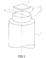
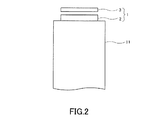
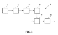
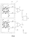
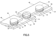
本発明の実施の形態について、図面を参照しながら詳細に説明する。図1は、本実施形態に係る回転角度検出装置の概略構成を示す斜視図であり、図2は、本実施形態に係る回転角度検出装置の概略構成を示す側面図であり、図3は、本実施形態における磁気検出装置の概略構成を示すブロック図であり、図4は、本実施形態における検出部の回路構成を概略的に示す回路図であり、図5は、本実施形態における磁気検出素子としてのMR素子の概略構成を示す斜視図である。 Embodiments of the present invention will be described in detail with reference to the drawings. FIG. 1 is a perspective view illustrating a schematic configuration of a rotation angle detection device according to the present embodiment, FIG. 2 is a side view illustrating a schematic configuration of the rotation angle detection device according to the present embodiment, and FIG. FIG. 4 is a block diagram illustrating a schematic configuration of a magnetic detection device according to the present embodiment, FIG. 4 is a circuit diagram schematically illustrating a circuit configuration of a detection unit according to the present embodiment, and FIG. 5 illustrates magnetic detection according to the present embodiment. It is a perspective view which shows schematic structure of the MR element as an element.
図1及び図2に示すように、本実施形態に係る回転角度検出装置1は、磁石2と、磁石2に対向して配置される磁気検出装置3とを備える。磁石2は、回転軸Cを中心として連続的に回転する軸部11(例えばサーボモータ等のモータ軸等)の軸方向の一端部に固定されており、軸部11の回転に連動して、回転軸Cを中心として回転する。
As shown in FIG. 1 and FIG. 2, the rotation
磁石2は、回転軸Cに直交する端面21と、回転軸Cを含む仮想平面を中心として対称に配置されたN極22及びS極23とを有し、回転軸Cに直交する方向(S極23からN極22に向かう方向であって、N極22とS極23との境界に直交する方向)に磁化されている。磁石2は、それが有する磁化に基づいて磁界を発生する。
The
磁気検出装置3は、磁石2の端面21に対向するように配置されており、磁石2による磁界を検出する。本実施形態に係る回転角度検出装置1は、磁気検出装置3の出力に基づいて磁石2の回転角度、すなわち回転移動する軸部11の回転角度を検出することができる。
The magnetic detection device 3 is disposed so as to face the
図3に示すように、磁気検出装置3は、検出部31、A/D(アナログ−デジタル)変換部32、演算処理部33、シミュレート部34、推定部35及び予測部36を有する。検出部31は、磁石2(図1、図2参照)の磁界を検出する。A/D変換部32は、検出部31から出力されるアナログ信号をデジタル信号に変換する。演算処理部33は、A/D変換部32によりデジタル変換されたデジタル信号を演算処理し、回転角度θを算出する。シミュレート部34は、推定部35により推定された回転角度θE、角速度ωE及び角速度αEに基づいて、所定のサンプリング時刻における回転角度θSをシミュレートする。推定部35は、シミュレート部34によりシミュレートされた回転角度θSと、演算処理部33により算出された回転角度θのうちの最新の回転角度θとに基づいて、所定のサンプリング時刻における回転角度θE、角速度ωE及び角加速度αEを推定する。予測部36は、推定部35による推定結果(回転角度θE、角速度ωE及び角加速度αE)に基づいて、現在サンプリング時刻における回転角度θPを予測する。本実施形態においては、少なくとも演算処理部33、シミュレート部34、推定部35及び予測部36により、連続的に作動する動作体(例えば連続的に回転するサーボモータのモータ軸等)の位置(回転位置)を予測可能な位置予測装置が構成される。
As illustrated in FIG. 3, the magnetic detection device 3 includes a
図4に示すように、検出部31は、第1の検出部31A及び第2の検出部31Bを含み、第1及び第2の検出部31A,31Bのそれぞれは、少なくとも1つの磁気検出素子を含む。検出部31は、所定のサンプリング周期(1サンプリング周期は、例えば50〜100μsec程度)で、磁石2の磁界の方向が所定の方向に対するなす角度(回転角度)に関する検出信号(アナログ信号)を生成し、出力する。
As shown in FIG. 4, the
第1及び第2の検出部31A,31Bのそれぞれは、少なくとも1つの磁気検出素子として、直列に接続された一対の磁気検出素子を含んでいてもよい。この場合において、第1及び第2の検出部31A,31Bのそれぞれは、直列に接続された第1の一対の磁気検出素子と、直列に接続された第2の一対の磁気検出素子とを含むホイートストンブリッジ回路を有する。
Each of the first and
第1の検出部31Aが有するホイートストンブリッジ回路311は、電源ポートV1と、グランドポートG1と、2つの出力ポートE11,E12と、直列に接続された第1の一対の磁気検出素子R11,R12と、直列に接続された第2の一対の磁気検出素子R13,R14とを含む。磁気検出素子R11,R13の各一端は、電源ポートV1に接続されている。磁気検出素子R11の他端は、磁気検出素子R12の一端と出力ポートE11とに接続されている。磁気検出素子R13の他端は、磁気検出素子R14の一端と出力ポートE12とに接続されている。磁気検出素子R12,R14の各他端は、グランドポートG1に接続されている。電源ポートV1には、所定の大きさの電源電圧が印加され、グランドポートG1はグランドに接続される。
The
第2の検出部31Bが有するホイートストンブリッジ回路312は、第1の検出部31Aのホイートストンブリッジ回路311と同様の構成を有し、電源ポートV2と、グランドポートG2と、2つの出力ポートE21,E22と、直列に接続された第1の一対の磁気検出素子R21,R22と、直列に接続された第2の一対の磁気検出素子R23,R24とを含む。磁気検出素子R21,R23の各一端は、電源ポートV2に接続されている。磁気検出素子R21の他端は、磁気検出素子R22の一端と出力ポートE21とに接続されている。磁気検出素子R23の他端は、磁気検出素子R24の一端と出力ポートE22とに接続されている。磁気検出素子R22,R24の各他端は、グランドポートG2に接続されている。電源ポートV2には、所定の大きさの電源電圧が印加され、グランドポートG2はグランドに接続される。
The
本実施形態において、ホイートストンブリッジ回路311,312に含まれるすべての磁気検出素子R11〜R14,R21〜R24として、TMR素子、GMR素子等のMR素子を用いることができ、特にTMR素子を用いるのが好ましい。TMR素子、GMR素子は、磁化方向が固定された磁化固定層と、印加される磁界の方向に応じて磁化方向が変化する自由層と、磁化固定層及び自由層の間に配置される非磁性層とを有する。
In the present embodiment, MR elements such as TMR elements and GMR elements can be used as all the magnetic detection elements R11 to R14 and R21 to R24 included in the
具体的には、図5に示すように、MR素子は、複数の下部電極41と、複数のMR膜50と、複数の上部電極42とを有する。複数の下部電極41は、基板(図示せず)上に設けられている。各下部電極41は細長い形状を有する。下部電極41の長手方向に隣接する2つの下部電極41の間には、間隙が形成されている。下部電極41の上面における、長手方向の両端近傍にそれぞれMR膜50が設けられている。MR膜50は、下部電極41側から順に積層された自由層51、非磁性層52、磁化固定層53及び反強磁性層54を含む。自由層51は、下部電極41に電気的に接続されている。反強磁性層54は、反強磁性材料により構成され、磁化固定層53との間で交換結合を生じさせることで、磁化固定層53の磁化の方向を固定する役割を果たす。複数の上部電極42は、複数のMR膜50上に設けられている。各上部電極42は細長い形状を有し、下部電極41の長手方向に隣接する2つの下部電極41上に配置され、隣接する2つのMR膜50の反強磁性層54同士を電気的に接続する。なお、MR膜50は、上部電極42側から順に自由層51、非磁性層52、磁化固定層53及び反強磁性層54が積層されてなる構成を有していてもよい。また、磁化固定層53を、強磁性層/非磁性中間層/強磁性層の積層フェリ構造とし、両強磁性層を反強磁性的に結合させてなる、いわゆるセルフピン止め型の固定層(Synthetic Ferri Pinned層,SFP層)とすることで、反強磁性層54が省略されていてもよい。
Specifically, as shown in FIG. 5, the MR element has a plurality of
TMR素子においては、非磁性層52はトンネルバリア層である。GMR素子においては、非磁性層52は非磁性導電層である。TMR素子、GMR素子において、自由層51の磁化の方向が磁化固定層53の磁化の方向に対してなす角度に応じて抵抗値が変化し、この角度が0°(互いの磁化方向が平行)のときに抵抗値が最小となり、180°(互いの磁化方向が反平行)のときに抵抗値が最大となる。
In the TMR element, the
図4において、磁気検出素子R11〜R14,R21〜R24の磁化固定層の磁化の方向を塗りつぶした矢印で表し、自由層の磁化の方向を白抜きの矢印で表す。第1の検出部31Aにおいて、磁気検出素子R11,R14の磁化固定層の磁化の方向は第1の方向D1に平行な方向であり、磁気検出素子R12,R13の磁化固定層の磁化の方向は、磁気検出素子R11,R14の磁化固定層の磁化の方向と反平行方向である。第1の検出部31Aにおいて、磁石2の磁界の第1の方向D1の成分の強度に応じて、出力ポートE11,E12の電位差が変化し、磁石2の磁界の第1の方向D1の強度を表す信号が出力される。
In FIG. 4, the magnetization directions of the magnetization fixed layers of the magnetic detection elements R11 to R14 and R21 to R24 are represented by solid arrows, and the magnetization directions of the free layers are represented by white arrows. In the
第2の検出部31Bにおいて、磁気検出素子R21,R24の磁化固定層の磁化の方向は第2の方向D2(第1の方向D1に直交する方向)であり、磁気検出素子R22,R23の磁化固定層の磁化の方向は、磁気検出素子R21,R24の磁化固定層の磁化の方向と反平行方向である。第2の検出部31Bにおいて、磁石2の磁界の第2の方向D2の成分の強度に応じて、出力ポートE21,E22の電位差が変化し、磁石2の磁界の第2の方向D2の強度を表す信号が出力される。
In the
差分検出器37は、出力ポートE11,E12の電位差に対応する信号を第1の信号S1としてA/D変換部32に出力する。差分検出器38は、出力ポートE21,E22の電位差に対応する信号を第2の信号S2としてA/D変換部32に出力する。
The
図4に示すように、第1の検出部31Aにおける磁気検出素子R11〜R14の磁化固定層の磁化方向と、第2の検出部31Bにおける磁気検出素子R21〜R24の磁化固定層の磁化方向とは、互いに直交する。この場合、第1の信号S1の波形は、回転角度θに依存したコサイン(Cosine)波形になり、第2の信号S2の波形は、回転角度θに依存したサイン(Sine)波形になる。本実施形態において、第2の信号S2の位相は、第1の信号S1の位相に対して信号周期の1/4、すなわちπ/2(90°)異なっている。
As shown in FIG. 4, the magnetization direction of the magnetization fixed layer of the magnetic detection elements R11 to R14 in the
A/D変換部32は、検出部31から所定のサンプリング周期で出力される、第1及び第2の信号(回転角度θに関するアナログ信号)S1,S2をデジタル信号に変換し、当該デジタル信号が演算処理部33に入力される。
The A /
演算処理部33は、A/D変換部32によりアナログ信号から変換されたデジタル信号についての演算処理を行い、磁石2の回転角度θを算出する。この演算処理部33は、例えば、マイクロコンピュータ等により構成される。演算処理部33により算出された磁石2の回転角度θは、演算処理部33に含まれる記憶部(図示せず)に記憶される。
The
磁石2の回転角度θは、例えば下記式で示すアークタンジェント計算によって算出され得る。
θ=atan(S1/S2)
The rotation angle θ of the
θ = atan (S1 / S2)
なお、360°の範囲内で、上記式における回転角度θの解には、180°異なる2つの値がある。しかし、第1の信号S1及び第2の信号S2の正負の組み合わせにより、回転角度θの真の値が、上記式における2つの解のいずれかであるかを判別することができる。すなわち、第1の信号S1が正の値のときは、回転角度θは0°よりも大きく180°よりも小さい。第1の信号S1が負の値のときは、回転角度θは180°よりも大きく360°よりも小さい。第2の信号S2が正の値のときは、回転角度θは0°以上90°未満及び270°より大きく360°以下の範囲内である。第2の信号S2が負の値のときは、回転角度θは90°よりも大きく270°よりも小さい。演算処理部33は、上記式と、第1の信号S1及び第2の信号S2の正負の組み合わせの判定とにより、360°の範囲内で回転角度θを算出する。
Note that, within the range of 360 °, the solution of the rotation angle θ in the above formula has two values that differ by 180 °. However, it is possible to determine whether the true value of the rotation angle θ is one of the two solutions in the above expression, by the positive / negative combination of the first signal S1 and the second signal S2. That is, when the first signal S1 is a positive value, the rotation angle θ is greater than 0 ° and smaller than 180 °. When the first signal S1 is a negative value, the rotation angle θ is greater than 180 ° and smaller than 360 °. When the second signal S2 is a positive value, the rotation angle θ is in the range of 0 ° to less than 90 ° and greater than 270 ° to 360 °. When the second signal S2 has a negative value, the rotation angle θ is greater than 90 ° and smaller than 270 °. The
シミュレート部34は、推定部35により推定され、記憶部に記憶されている過去のサンプリング時刻における磁石2の回転角度θE、角速度ωE及び角加速度αEから、所定のサンプリング時刻における磁石2の回転角度θSをシミュレートする。例えば、シミュレート部34は、推定部35により推定された過去のサンプリング時刻における磁石2の回転角度θE等について、例えば外挿処理等を行うことで、所定のサンプリング時刻における磁石2の回転角度θSをシミュレートすることができる。
The
推定部35は、シミュレート部34により求められた磁石2の回転角度θSに所定のサンプリング時刻における磁石2の回転角度θを反映させることで、当該所定のサンプリング時刻における磁石2の回転角度θEを推定するとともに、角速度ωE及び角加速度αEを推定する。
The
予測部36は、推定部35により推定された磁石2の回転角度θE、角速度ωE及び角加速度αEに基づいて、現在サンプリング時刻における磁石2の回転角度θPを予測する。例えば、予測部36は、推定部35により推定された磁石2の回転角度θE等について、例えば外挿処理等を行うことで、現在サンプリング時刻における磁石2の回転角度θPを算出する。
The
上記構成を有する回転角度検出装置1において、軸部11の回転に伴い磁石2が回転すると、磁石2の磁界が変化する。その磁界の変化に応じ、検出部31の磁気検出素子R11〜R14,R21〜R24の抵抗値が変化し、第1の検出部31A及び第2の検出部31Bのそれぞれの出力ポートE11,E12,E21,E22の電位差に応じ、所定のサンプリング周期で第1の方向D1及び第2の方向D2における磁石2の磁界強度を表す信号S1,S2が差分検出器37,38から出力される。そして、差分検出器37,38から出力された第1の信号S1及び第2の信号S2が出力され、A/D変換部32によりデジタル信号に変換される。その後、演算処理部33により、磁石2の回転角度θが算出される。
In the rotation
本実施形態に係る回転角度検出装置1において、検出部31からの出力に基づくアナログ信号についてのフィルタリング処理、A/D変換部32にてデジタル信号に変換する処理、デジタル信号についてのフィルタリング処理、演算処理部33における演算処理等により遅延が生じる。この遅延を取り戻すために、予測部36による回転角度の予測が重要となる。
In the rotation
例えば、本実施形態に係る回転角度検出装置1にて、種々の処理により3サンプリング時刻分の遅延が生じるものとする。すると、現在サンプリング時刻Tnにおいて、現在サンプリング時刻Tnよりも3サンプリング時刻前Tn-3における磁石2の回転角度θn-3が、演算処理部33により算出される。一方で、シミュレート部34は、例えば、推定部35により推定された、現在サンプリング時刻Tnよりも4サンプリング時刻前Tn-4における磁石2の回転角度θEn-4、角速度ωEn-4及び角加速度αEn-4に基づいて、現在サンプリング時刻Tnよりも3サンプリング時刻前Tn-3における磁石の回転角度θSn-3をシミュレートして求める。推定部35は、シミュレート部34によりシミュレートされた磁石2の回転角度θSn-3に、演算処理部33により算出された磁石2の回転角度θn-3(現在サンプリング時刻Tnにおける最新の磁石2の回転角度)を反映させて、3サンプリング時刻前Tn-3における磁石2の回転角度θEn-3を推定するとともに、角速度ωEn-3及び角加速度αEn-3を推定する。そして、予測部36は、推定部35により推定された磁石2の回転角度θEn-3、角速度ωEn-3及び角加速度αEn-3に基づき、現在サンプリング時刻Tnにおける磁石2の回転角度θPnを予測する。
For example, in the rotation
ここで、演算処理部33により算出される磁石の回転角度θには、所定のノイズが含まれる。このノイズを含む回転角度θに基づいて現在サンプリング時刻Tnにおける回転角度θPnを予測しようとすると、予測される回転角度θPnの予測値に含まれるノイズが増幅されてしまい、正確な予測が困難となる。また、本発明者が先に提案した角速度ωや角加速度αを用いた予測方法(特願2015−67498号)においては、予測される回転角度θPnに含まれるノイズの低減が可能であるものの、回転角度θPnの予測値が、演算処理部33にて算出される回転角度θnからずれてしまうおそれがある。当該予測方法においては、高速で回転動作する動作体において、サンプリング周期のうちの極めて短期間(例えば、現在サンプリング時刻Tnから遡って3サンプリング周期以下程度)であれば磁石2の回転運動を等速度回転運動又は等加速度回転運動と仮定し、3サンプリング時刻前Tn-3における角速度ωn-3や角加速度αn-3と、現在サンプリング時刻Tnにおける角速度ωnや角加速度αnとは実質的に同一であると仮定可能であることを前提とし、3サンプリング時刻前Tn-3における磁石2の回転角度θn-3の実測値(演算処理部により算出された回転角度θn-3)から算出された角速度ωn-3や角加速度αn-3に基づいて現在サンプリング時刻Tnにおける磁石2の回転角度θPnを予測することで、回転角度θPnに含まれるノイズを低減することができる。しかし、現在サンプリング時刻Tnにおける磁石2の回転角度θPnを予測するために用いられる3サンプリング時刻前Tn-3における回転角度θn-3が実測値(演算処理部33により算出された回転角度θn-3)であることで、予測部36により予測される回転角度θPnが実測値からずれてしまうという問題が生じるものと推察される。
Here, the magnet rotation angle θ calculated by the
この点、本実施形態においては、現在サンプリング時刻Tnにおける磁石2の回転角度θPnを予測するために用いられる3サンプリング時刻前Tn-3における回転角度θEn-3、角速度ωEn-3及び角加速度αEn-3が推定値であることで、予測部36により予測される回転角度θPnが演算処理部33により算出される回転角度θnからずれてしまうという問題を解消することができ、現在サンプリング時刻Tnにおける磁石2の回転角度θPnを極めて精確に予測することができる。
In this regard, in the present embodiment, the rotation angle θ En-3 and the angular velocity ω En-3 at T n-3 three sampling times before are used to predict the rotation angle θ Pn of the
このように、予測部36により極めて精確に予測される磁石2の回転角度θPnは、軸部11を含む動作体(例えばモータ軸を含むサーボモータ等)の駆動回路等(図示せず)に入力され、当該動作体の動作制御が行われる。したがって、当該動作体の動作制御を高い精度で行うことができる。
Thus, the rotation angle θ Pn of the
上述したように、本実施形態に係る回転角度検出装置1によれば、予測部36により現在サンプリング時刻Tnにおける回転角度θPnを予測するために用いられる回転角度θEn-3、角速度ωEn-3及び角加速度αEn-3が、現在サンプリング時刻Tnのときに演算処理部33により算出される過去のサンプリング時刻における回転角度θn-3を、シミュレート部34によりシミュレートされた回転角度θSn-3に反映させることで求められるため、当該回転角度θEn-3、角速度ωEn-3及び角加速度αEn-3に基づき、現在サンプリング時刻Tnの回転角度θPnを極めて精確に予測することができる。
As described above, according to the rotation
また、本実施形態に係る回転角度検出装置1によれば、現在サンプリング時刻Tnにおける磁石2の回転角度θPnを予測するために推定部35により推定される回転角度θEn-3、角速度ωEn-3及び角加速度αEn-3が、シミュレート部34がシミュレートした回転角度θSn-3と演算処理部33が算出した最新の回転角度θn-3とを用いるだけで求められるため、当該回転角度θPnの予測のために必要な情報量(サンプル数)を少なくすることができるという効果も奏し得る。
Further, according to the rotation
以上説明した実施形態は、本発明の理解を容易にするために記載されたものであって、本発明を限定するために記載されたものではない。したがって、上記実施形態に開示された各要素は、本発明の技術的範囲に属する全ての設計変更や均等物をも含む趣旨である。 The embodiment described above is described for facilitating understanding of the present invention, and is not described for limiting the present invention. Therefore, each element disclosed in the above embodiment is intended to include all design changes and equivalents belonging to the technical scope of the present invention.
上記実施形態において、予測部36は、現在サンプリング時刻Tnにおける回転角度θPnを予測する態様を例に挙げて説明したが、本発明はこのような態様に限定されるものではなく、例えば、現在サンプリング時刻Tnよりも未来(例えば3サンプリング時刻先Tn+3の回転角度θPn+3を予測してもよい。
In the above embodiment, the
上記実施形態において、磁界発生部として軸部11に固定された磁石2を用いているが、本発明はこのような態様に限定されるものではなく、例えば、少なくとも1組のN極及びS極が交互にリング状に配置された磁石を磁界発生部として用い、当該磁石の外周部に磁気検出装置を対向配置させてなるものであってもよいし、直線状スケールを磁界発生部として用いてもよい。
In the above embodiment, the
上記実施形態において、磁石2が固定された軸部11が回転軸Cを中心に回転することにより磁石2が磁気検出装置3に対して相対的に回転移動するが、本発明はこのような態様に限定されるものではない。例えば、磁石2(軸部11)と磁気検出装置3とが、互いに反対方向に回転するものであってもよいし、磁石2(軸部11)が回転せずに磁気検出装置3が回転するものであってもよい。
In the above-described embodiment, the
以下、実施例等を挙げて本発明をさらに詳細に説明するが、本発明は下記の実施例等に何ら限定されるものではない。 EXAMPLES Hereinafter, although an Example etc. are given and this invention is demonstrated further in detail, this invention is not limited to the following Example etc. at all.
〔実施例1〕
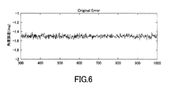
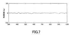
図3及び図4に示す構成を有する磁気検出装置3における、予測部36による現在サンプリング時刻Tnにおける回転角度θPnの予測に関し、MATLABを用いてシミュレーションを行い、回転角度θPnの予測値に含まれるノイズを求めた。かかるシミュレーションにおいて、磁石2が10000deg/secで等速回転運動し、検出部31によるサンプリング周期が50μsecであり、演算処理部33により算出される回転角度θに含まれるノイズが±0.1degであり(図6参照)、3サンプリング時刻分(150μsec)の群遅延が生じるものとした。また、シミュレート部34は、4サンプリング時刻前Tn-4における回転角度θEn-4、角速度ωEn-4及び角加速度En-4を用いた外挿処理により3サンプリング時刻前Tn-3の回転角度θSn-3をシミュレートし、推定部35は、3サンプリング時刻前Tn-3の回転角度θn-3を回転角度θSn-3に反映させることで回転角度θEn-3、角速度ωEn-3及び角加速度αEn-3を推定し、それらの推定値θEn-3、ωEn-3、αEn-3を用いた線形外挿処理によって、予測部36が回転角度θPnを予測するものとした。シミュレーション結果を図7に示す。
[Example 1]
With respect to the prediction of the rotation angle θ Pn at the current sampling time T n by the
〔比較例1〕
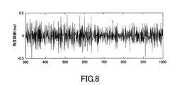
演算処理部33により算出された3サンプリング時刻Tn-3〜Tn-5における回転角度θn-3〜θn-5を用いて線形外挿処理を行うことで現在サンプリング時刻Tnにおける回転角度θPnの予測をすることとした以外は、実施例1と同様にして回転角度θPnの予測値に含まれるノイズを求めた。シミュレーション結果を図8に示す。
[Comparative Example 1]
Rotation at the current sampling time T n by performing a linear extrapolation process using the rotation angle θ n-3 ~θ n-5 at 3 sampling time T n-3 through T n-5 that has been calculated by the
〔比較例2〕
4サンプリング時刻Tn-3〜Tn-6における回転角度θn-3〜θn-6をそれぞれ1回微分した角速度ωn-3〜ωn-6を用いた移動平均フィルタ処理を行うことで現在サンプリング時刻Tnにおける回転角度θPnを予測することとした以外は、実施例1と同様にして回転角度θPnの予測値に含まれるノイズを求めた。シミュレーション結果を図9に示す。
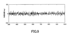
[Comparative Example 2]
4 sampling time T n-3 ~T n-6 rotation angle θ n-3 ~θ n-6 moving average filter processing by performing with the angular velocity ω n-3 ~ω n-6 obtained by differentiating once, respectively, in Thus, noise included in the predicted value of the rotation angle θ Pn was obtained in the same manner as in Example 1 except that the rotation angle θ Pn at the current sampling time T n was predicted. The simulation result is shown in FIG.
実施例1、比較例1及び比較例2の結果(図7〜9参照)から明らかなように、推定部34により推定された回転角度θEn-3、角速度ωEn-3及び角加速度αEn-3を用いた予測により、回転角度θに所定のノイズが含まれていたとしても、そのノイズを増幅させることなく、現在サンプリング時刻Tnの回転角度θPnを極めて精確に予測可能であることが確認された。
As is clear from the results of Example 1, Comparative Example 1 and Comparative Example 2 (see FIGS. 7 to 9), the rotation angle θ En-3 , the angular velocity ω En-3 and the angular acceleration α En estimated by the
〔実施例2〕
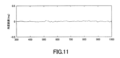
磁石2が2×10⁸deg/sec2で等加速回転運動しているものとし、演算処理部33により算出される回転角度θに含まれるノイズが、図10に示すように速度が大きくなるに従い増大することとした以外は、実施例1と同様にして回転角度θPnの予測値に含まれるノイズを求めた。結果を図11に示す。
[Example 2]
Assuming that the
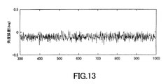
〔比較例3〕
演算処理部33により算出された3サンプリング時刻Tn-3〜Tn-5における回転角度θn-3〜θn-5を用いて線形外挿処理を行うことで現在サンプリング時刻Tnにおける回転角度θPnの予測をすることとした以外は、実施例2と同様にして回転角度θPnの予測値に含まれるノイズを求めた。シミュレーション結果を図12に示す。
[Comparative Example 3]
Rotation at the current sampling time T n by performing a linear extrapolation process using the rotation angle θ n-3 ~θ n-5 at 3 sampling time T n-3 through T n-5 that has been calculated by the
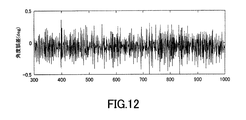
〔比較例4〕
4サンプリング時刻Tn-3〜Tn-6における回転角度θn-3〜θn-6をそれぞれ2回微分した角加速度αn-3〜αn-6を用いた移動平均フィルタ処理を行うことで現在サンプリング時刻Tnにおける回転角度θPnを予測することとした以外は、実施例2と同様にして回転角度θPnの予測値に含まれるノイズを求めた。シミュレーション結果を図13に示す。
[Comparative Example 4]
4. Moving average filter processing using angular accelerations α n-3 to α n-6 obtained by differentiating the rotation angles θ n-3 to θ n- 6 twice at four sampling times T n-3 to T n-6 is performed. Thus, noise included in the predicted value of the rotation angle θ Pn was obtained in the same manner as in Example 2 except that the rotation angle θ Pn at the current sampling time T n was predicted. The simulation result is shown in FIG.
実施例2、比較例3及び比較例4の結果(図11〜13参照)から明らかなように、推定部34により推定された回転角度θEn-3、角速度ωEn-3及び角加速度αEn-3を用いた予測により、回転角度θに所定のノイズが含まれていたとしても、そのノイズを低減させ、かつ現在サンプリング時刻Tnの回転角度θPnの予測値が真の値(演算処理部33により算出される回転角度θn)からはずれることなく、極めて精確に予測可能であることが確認された。
As is clear from the results of Example 2, Comparative Example 3 and Comparative Example 4 (see FIGS. 11 to 13), the rotation angle θ En-3 , the angular velocity ω En-3 and the angular acceleration α En estimated by the
1…回転角度検出装置(位置検出装置)
2…磁石(磁界発生部)
3…磁気検出装置
31…検出部
33…演算処理部
34…シミュレート部
35…推定部
36…予測部
1 ... Rotation angle detection device (position detection device)
2 ... Magnet (magnetic field generator)
DESCRIPTION OF SYMBOLS 3 ...
Claims (5)
前記所定時刻よりも過去の第1時刻における前記動作体の推定位置状態を求める推定部と、
前記推定部により推定された前記動作体の推定位置状態に基づき、前記動作体の前記所定時刻における位置を予測する位置予測部と、
前記動作体に設けられている磁界発生部の外部磁界を検出することで出力される前記動作体の位置に関する信号に基づき、前記動作体の位置状態を算出する演算処理部と、
前記推定部により推定された、前記第1時刻よりも過去の第2時刻における前記動作体の推定位置状態に基づいて、前記動作体の前記第1時刻におけるシミュレート位置状態を求めるシミュレート部と
を備え、
前記推定部は、前記シミュレート部により求められた前記第1時刻における前記動作体の前記シミュレート位置状態と、前記演算処理部により算出された前記第1時刻における前記動作体の前記位置状態とに基づいて、前記動作体の前記第1時刻における前記推定位置状態を求めることを特徴とする位置予測装置。 An apparatus for predicting a position at a predetermined time of an operating body that operates continuously,
An estimation unit for obtaining an estimated position state of the operating body at a first time that is earlier than the predetermined time;
A position predicting unit that predicts the position of the moving object at the predetermined time based on the estimated position state of the moving object estimated by the estimating unit ;
An arithmetic processing unit that calculates a position state of the operating body based on a signal related to the position of the operating body that is output by detecting an external magnetic field of a magnetic field generating unit provided in the operating body;
A simulation unit that obtains a simulated position state of the moving body at the first time based on an estimated position state of the moving body at a second time that is past the first time, estimated by the estimating unit;
Equipped with a,
The estimation unit includes the simulated position state of the moving body at the first time obtained by the simulating unit, and the position state of the moving body at the first time calculated by the arithmetic processing unit. based on the position predicting device according to claim Rukoto determined the estimated position state in the first time of the operation member.
前記推定部は、前記動作体の前記位置推定時刻における回転角度、角速度及び角加速度の推定値を前記推定位置状態として求めることを特徴とする請求項1又は2に記載の位置予測装置。 The operating body is a rotating body that rotates about a predetermined rotation axis;
The estimating unit, position prediction device according to claim 1 or 2, characterized in that determining the rotation angle at the position estimation time of the operation member, the estimated value of the angular velocity and angular acceleration as the state the estimated position.
前記動作体に設けられてなる前記磁界発生部に対向して配置され、前記動作体の位置を検出可能な検出部と
を備えることを特徴とする位置検出装置。 The position prediction apparatus according to any one of claims 1 to 3 ,
Wherein is arranged to face the magnetic field generating portion thus provided for the operation member, the position detecting device characterized by comprising a detectable detection unit the position of the operation member.
Priority Applications (5)
| Application Number | Priority Date | Filing Date | Title |
|---|---|---|---|
| JP2017062065A JP6361769B1 (en) | 2017-03-28 | 2017-03-28 | Position prediction apparatus and position detection apparatus |
| US15/805,289 US10352727B2 (en) | 2017-03-28 | 2017-11-07 | Position forecasting apparatus and position detection apparatus |
| DE102017126610.0A DE102017126610A1 (en) | 2017-03-28 | 2017-11-13 | Position prediction device and position detection device |
| CN201711297303.4A CN108662969B (en) | 2017-03-28 | 2017-12-08 | Position prediction device and position detection device |
| US16/426,095 US10697798B2 (en) | 2017-03-28 | 2019-05-30 | Position forecasting apparatus and position detection apparatus |
Applications Claiming Priority (1)
| Application Number | Priority Date | Filing Date | Title |
|---|---|---|---|
| JP2017062065A JP6361769B1 (en) | 2017-03-28 | 2017-03-28 | Position prediction apparatus and position detection apparatus |
Publications (2)
| Publication Number | Publication Date |
|---|---|
| JP6361769B1 true JP6361769B1 (en) | 2018-07-25 |
| JP2018165619A JP2018165619A (en) | 2018-10-25 |
Family
ID=62976532
Family Applications (1)
| Application Number | Title | Priority Date | Filing Date |
|---|---|---|---|
| JP2017062065A Active JP6361769B1 (en) | 2017-03-28 | 2017-03-28 | Position prediction apparatus and position detection apparatus |
Country Status (4)
| Country | Link |
|---|---|
| US (2) | US10352727B2 (en) |
| JP (1) | JP6361769B1 (en) |
| CN (1) | CN108662969B (en) |
| DE (1) | DE102017126610A1 (en) |
Families Citing this family (4)
| Publication number | Priority date | Publication date | Assignee | Title |
|---|---|---|---|---|
| JP6939754B2 (en) * | 2018-11-22 | 2021-09-22 | Tdk株式会社 | Angle sensor and angle sensor system |
| JP6908066B2 (en) * | 2019-03-18 | 2021-07-21 | Tdk株式会社 | Signal processing circuits, position detectors and magnetic sensor systems |
| US12107710B2 (en) | 2020-11-19 | 2024-10-01 | Allegro Microsystems, Llc | Sensor signaling of absolute and incremental data |
| US12104900B2 (en) * | 2022-09-29 | 2024-10-01 | Allegro Microsystems, Llc | Sensor with estimated real-time parameter data |
Citations (5)
| Publication number | Priority date | Publication date | Assignee | Title |
|---|---|---|---|---|
| JP2008116300A (en) * | 2006-11-02 | 2008-05-22 | Ntn Corp | Rotation detector and bearing with the rotation detector |
| JP2010173373A (en) * | 2009-01-27 | 2010-08-12 | Mitsubishi Electric Corp | Analysis operation assistance program and information processor for artificial satellite |
| EP2916107A1 (en) * | 2014-03-05 | 2015-09-09 | Siemens Aktiengesellschaft | Extrapolation of the exact position for a position encoder with phase-modulated raw signal |
| JP2016186475A (en) * | 2015-03-27 | 2016-10-27 | Tdk株式会社 | Position prediction device and position detection device |
| WO2016204205A1 (en) * | 2015-06-17 | 2016-12-22 | 旭化成エレクトロニクス株式会社 | Detection device, rotation angle detection device, detection method, and program |
Family Cites Families (23)
| Publication number | Priority date | Publication date | Assignee | Title |
|---|---|---|---|---|
| JPH0349588A (en) * | 1989-07-14 | 1991-03-04 | Omron Corp | Discrete-time ac motor control apparatus |
| US5187664A (en) * | 1990-11-27 | 1993-02-16 | Eaton-Kenway, Inc. | Proportional position-sensing system for an automatic guided vehicle |
| JP3367260B2 (en) | 1995-03-24 | 2003-01-14 | 三菱電機株式会社 | Encoder device and servo motor control device |
| GB2414300B (en) | 2004-02-12 | 2006-09-20 | Weston Aerospace | Signal processing method and apparatus |
| DE102004046803B4 (en) | 2004-09-27 | 2011-08-18 | Infineon Technologies AG, 81669 | Method for determining the angular position of a rotating object and rotary encoder |
| JP4689435B2 (en) * | 2004-12-16 | 2011-05-25 | アルプス電気株式会社 | Angle detection sensor |
| US7538700B2 (en) * | 2005-05-11 | 2009-05-26 | Toyota Jidosha Kabushiki Kaisha | Angular position detector and rotary electric device drive unit including the same |
| US7456599B2 (en) | 2005-05-31 | 2008-11-25 | Rockwell Automation Technologies, Inc. | Position feedback device with prediction |
| JP4925789B2 (en) | 2006-11-02 | 2012-05-09 | Ntn株式会社 | Rotation detection device and bearing with rotation detection device |
| EP2221588B1 (en) * | 2007-11-20 | 2015-01-14 | Sumida Corporation | Rotation angle detecting sensor |
| US8729889B2 (en) * | 2008-01-18 | 2014-05-20 | C-Sigma S.R.L. | Method and apparatus for magnetic contactless measurement of angular and linear positions |
| CN102016513B (en) * | 2009-03-30 | 2013-04-10 | 日立金属株式会社 | Rotation angle detection device |
| US8096271B2 (en) * | 2009-06-01 | 2012-01-17 | GM Global Technology Operations LLC | System and method for determining a camshaft position in a variable valve timing engine |
| JP5096442B2 (en) * | 2009-11-17 | 2012-12-12 | 株式会社日立製作所 | Rotation angle measuring device, motor system and electric power steering system |
| EP2564084B1 (en) * | 2010-04-26 | 2014-12-31 | Schaeffler Technologies GmbH & Co. KG | Roller bearing arrangement with an angle sensor |
| US9098077B2 (en) * | 2010-08-25 | 2015-08-04 | Mitsubishi Electric Corporation | Trajectory control device |
| US8754640B2 (en) * | 2012-06-18 | 2014-06-17 | Allegro Microsystems, Llc | Magnetic field sensors and related techniques that can provide self-test information in a formatted output signal |
| JP5979246B2 (en) * | 2012-12-11 | 2016-08-24 | トヨタ自動車株式会社 | Vehicle state detection device |
| US9042716B2 (en) * | 2013-08-15 | 2015-05-26 | Allegro Microsystems, Llc | Method and apparatus for determining linear position using multiple magnetic field sensors |
| EP3040690B1 (en) * | 2013-08-26 | 2021-03-03 | Mitsubishi Electric Corporation | Angle error correction device and angle error correction method for position detector |
| JP6210284B2 (en) * | 2013-09-18 | 2017-10-11 | 株式会社ジェイテクト | Rotation angle detector |
| JP6157300B2 (en) | 2013-09-30 | 2017-07-05 | 太平洋セメント株式会社 | Cement kiln exhaust gas treatment method |
| JP6191840B2 (en) * | 2015-07-31 | 2017-09-06 | Tdk株式会社 | Angle sensor correction device, correction method, and angle sensor |
-
2017
- 2017-03-28 JP JP2017062065A patent/JP6361769B1/en active Active
- 2017-11-07 US US15/805,289 patent/US10352727B2/en active Active
- 2017-11-13 DE DE102017126610.0A patent/DE102017126610A1/en active Pending
- 2017-12-08 CN CN201711297303.4A patent/CN108662969B/en active Active
-
2019
- 2019-05-30 US US16/426,095 patent/US10697798B2/en active Active
Patent Citations (5)
| Publication number | Priority date | Publication date | Assignee | Title |
|---|---|---|---|---|
| JP2008116300A (en) * | 2006-11-02 | 2008-05-22 | Ntn Corp | Rotation detector and bearing with the rotation detector |
| JP2010173373A (en) * | 2009-01-27 | 2010-08-12 | Mitsubishi Electric Corp | Analysis operation assistance program and information processor for artificial satellite |
| EP2916107A1 (en) * | 2014-03-05 | 2015-09-09 | Siemens Aktiengesellschaft | Extrapolation of the exact position for a position encoder with phase-modulated raw signal |
| JP2016186475A (en) * | 2015-03-27 | 2016-10-27 | Tdk株式会社 | Position prediction device and position detection device |
| WO2016204205A1 (en) * | 2015-06-17 | 2016-12-22 | 旭化成エレクトロニクス株式会社 | Detection device, rotation angle detection device, detection method, and program |
Also Published As
| Publication number | Publication date |
|---|---|
| US10697798B2 (en) | 2020-06-30 |
| US20180283903A1 (en) | 2018-10-04 |
| US20190277662A1 (en) | 2019-09-12 |
| CN108662969A (en) | 2018-10-16 |
| CN108662969B (en) | 2020-06-23 |
| JP2018165619A (en) | 2018-10-25 |
| DE102017126610A1 (en) | 2018-10-04 |
| US10352727B2 (en) | 2019-07-16 |
Similar Documents
| Publication | Publication Date | Title |
|---|---|---|
| US10697798B2 (en) | Position forecasting apparatus and position detection apparatus | |
| JP6197839B2 (en) | Rotation detector | |
| JP7153012B2 (en) | Determining system for determining at least one rotational parameter of a rotating member | |
| WO2009126200A2 (en) | Gear tooth sensor with single magnetoresistive bridge | |
| JP6194914B2 (en) | Position prediction apparatus and position detection apparatus | |
| JP2017138143A (en) | Displacement detection device and angular speed detection device | |
| JP2003215145A (en) | Rotational frequency detector | |
| CN106066461B (en) | Magnetoresistive devices | |
| JP6939754B2 (en) | Angle sensor and angle sensor system | |
| JP6947194B2 (en) | Signal processing circuit and magnetic sensor system | |
| US11313666B2 (en) | Angle sensor and angle sensor system | |
| CN107229020A (en) | Magnetic sensor | |
| JP2018115929A (en) | Electric current sensor signal correction method, and electric current sensor | |
| JP7242352B2 (en) | A system for determining at least one rotational parameter of a rotating member | |
| US20080218159A1 (en) | Sensor System For Determining a Position or a Rotational Speed of an Object | |
| CN114646335A (en) | Apparatus and method for position detection | |
| CN110749276B (en) | Angle sensor correction device and angle sensor | |
| CN110749277B (en) | Angle sensor correction device and angle sensor | |
| JP7156249B2 (en) | Position detector | |
| US9612135B2 (en) | Device for determining motion parameters | |
| JP2020153980A (en) | System for determining at least one rotation parameter of rotating member | |
| JP4917522B2 (en) | Position sensor | |
| JP2009041949A (en) | Magnetic acceleration sensor | |
| JP2010223595A (en) | Position detection device | |
| JP2020153981A (en) | System for determining at least one rotation parameter of rotating member |
Legal Events
| Date | Code | Title | Description |
|---|---|---|---|
| A621 | Written request for application examination |
Free format text: JAPANESE INTERMEDIATE CODE: A621 Effective date: 20170328 |
|
| A131 | Notification of reasons for refusal |
Free format text: JAPANESE INTERMEDIATE CODE: A131 Effective date: 20180306 |
|
| A521 | Request for written amendment filed |
Free format text: JAPANESE INTERMEDIATE CODE: A523 Effective date: 20180426 |
|
| TRDD | Decision of grant or rejection written | ||
| A01 | Written decision to grant a patent or to grant a registration (utility model) |
Free format text: JAPANESE INTERMEDIATE CODE: A01 Effective date: 20180529 |
|
| A61 | First payment of annual fees (during grant procedure) |
Free format text: JAPANESE INTERMEDIATE CODE: A61 Effective date: 20180611 |
|
| R150 | Certificate of patent or registration of utility model |
Ref document number: 6361769 Country of ref document: JP Free format text: JAPANESE INTERMEDIATE CODE: R150 |
|
| RD04 | Notification of resignation of power of attorney |
Free format text: JAPANESE INTERMEDIATE CODE: A7424 Effective date: 20200305 |
|
| R250 | Receipt of annual fees |
Free format text: JAPANESE INTERMEDIATE CODE: R250 |